

Geberit ESG 3 Maintenance Manual
ESG 3
Maintenance
Manual
Instandhaltungsanleitung
Manuel d’entretien
Istruzioni per la manutenzione

EN
Information
Table of Contents
Information.......................................................................................................................................................................................... 2
Safety.................................................................................................................................................................................................... 3
Inspection............................................................................................................................................................................................ 4
Repair .................................................................................................................................................................................................... 5
Troubleshooting ............................................................................................................................................................................. 13
Product
This document contains all the information required for the professional maintenance of the following
products:
• 359.911.1P.1 Geberit electrofusion machine ESG 3 [115 V]
• 359.911.Px.x Geberit electrofusion machine ESG 3 [230 V]
2
D68129-001 © 04-2014
966.653.00.0 (00)
Safety
Target group
Maintenance and repair on this product may only be performed by skilled persons in accordance with
EN IEC 62079:2001.
Intended use
The Geberit electrofusion machine ESG 3 may only be used for welding:
• Geberit electrofusion sleeve couplings ø 40–160 mm with Geberit PE and Geberit Silent-db20 pipes and
fittings
• Geberit electrofusion tapes for anchor points ø 50–315 mm with Geberit PE pipes and fittings
Any other use, or use extending beyond the intended application, is deemed to be improper. Geberit will not
accept any liability for any resulting damage.
Basic safety notes
Before executing any maintenance tasks, read the operating instructions and safety notes in document
966.475.00.0.
EN
D68129-001 © 04-2014
966.653.00.0 (00)
3
EN
Inspection
Visual check
Check the electrofusion machine for visual defects:
•cuts
•bumps
• excessive pollution
Completeness
Check the electrofusion machine for completeness:
• electrofusion sleeve coupling cable
• connecting cable for electrofusion coupling with integrated thermal fuse
• connecting cable set
•operation manual
•snap cover
• carrying belt
4
D68129-001 © 04-2014
966.653.00.0 (00)
Repair
EN
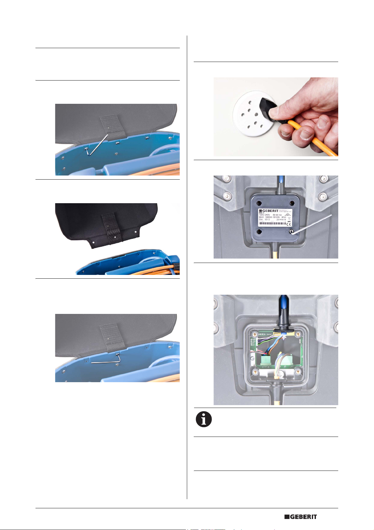
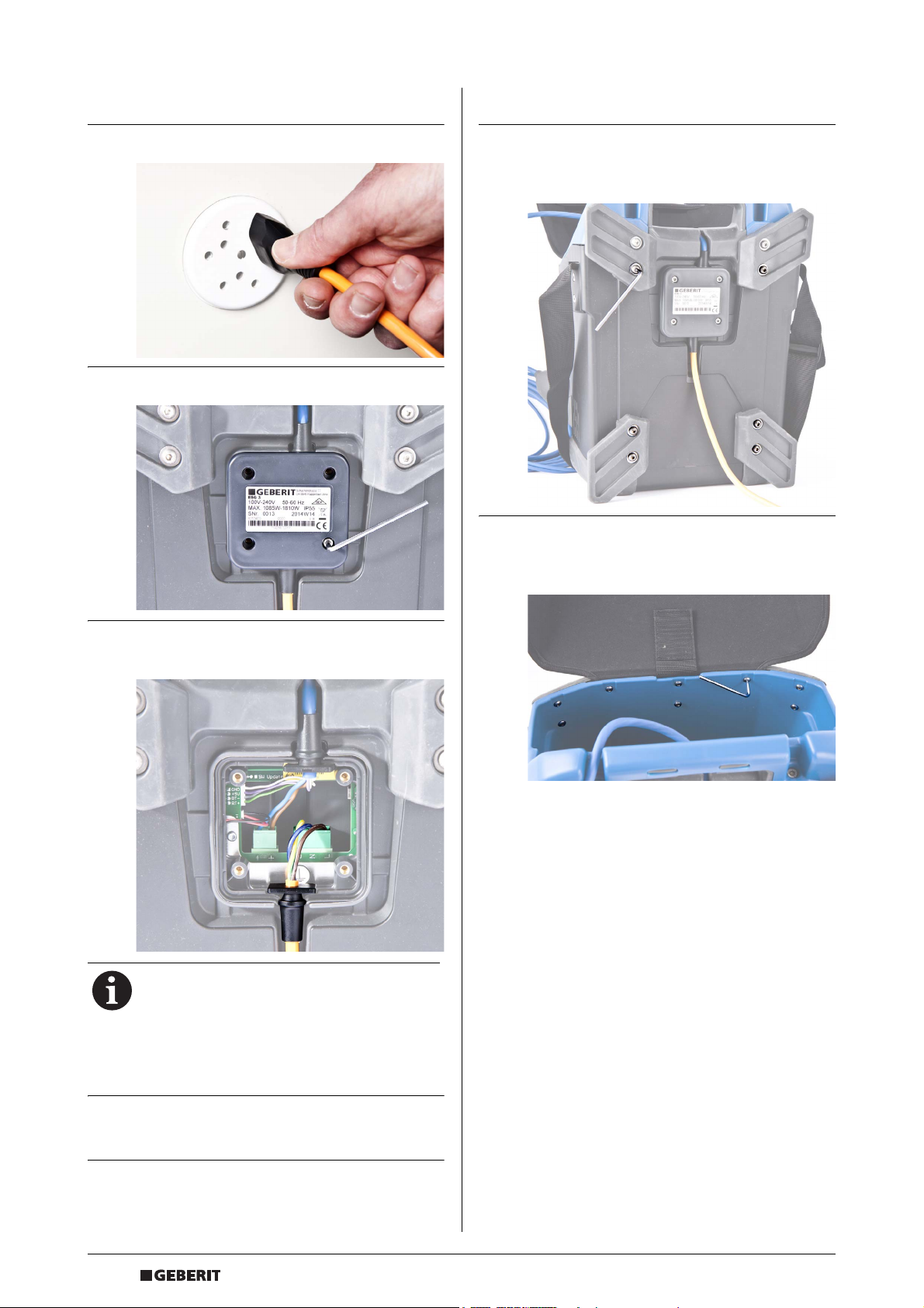
Replacing the remote control
cable
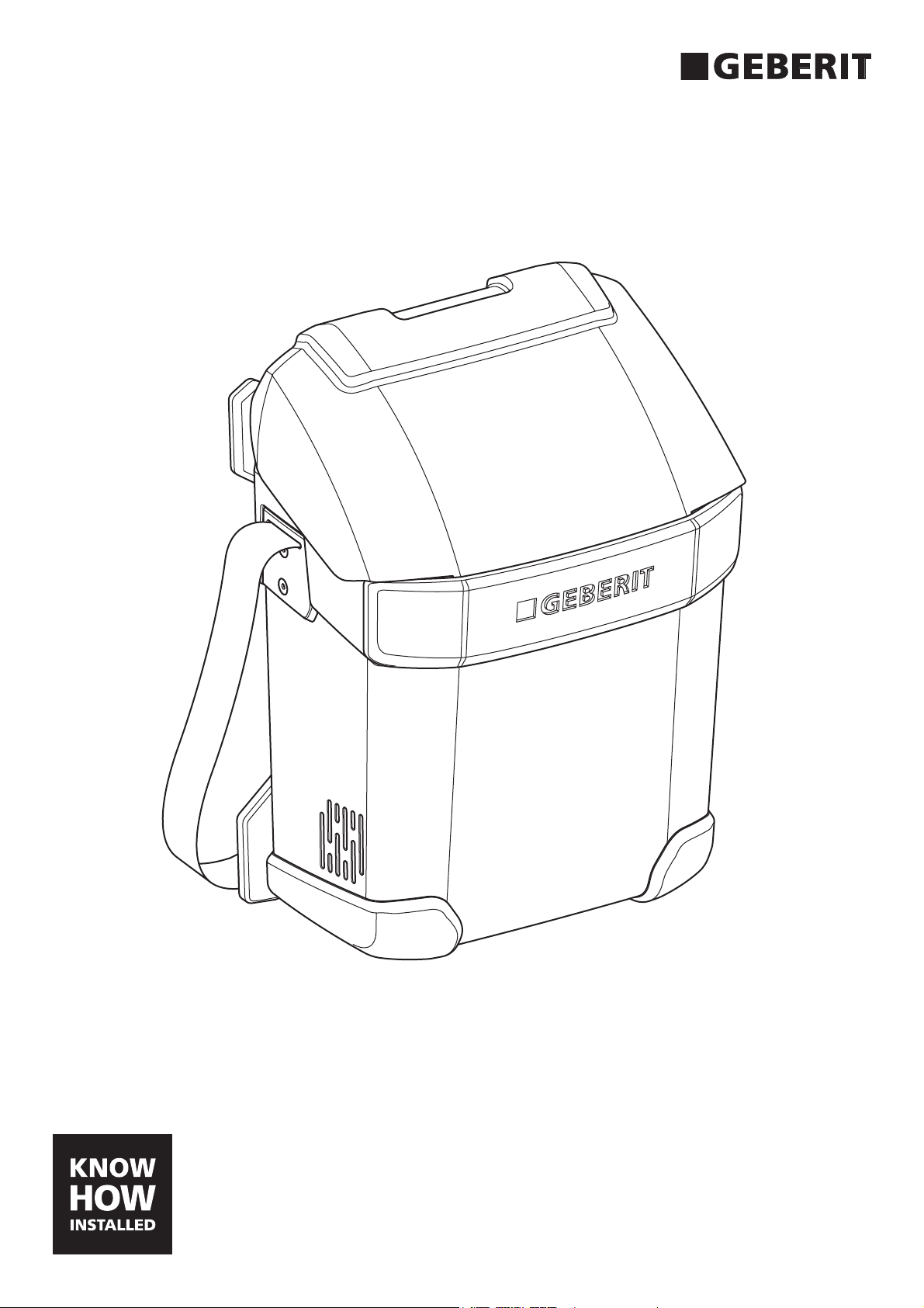
Replacing the snap cover
1 Remove the three screws on the inside of
the upper housing.
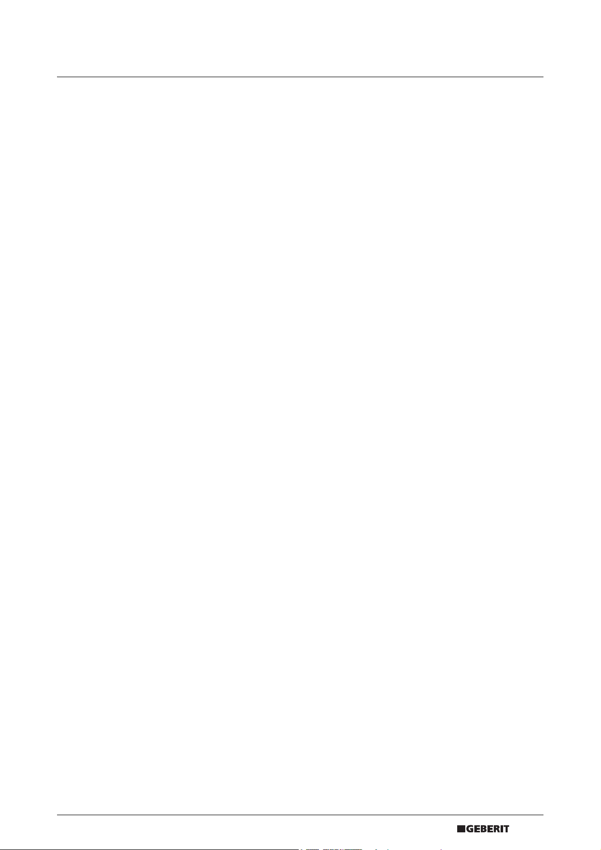
2 Remove the damaged cover and mount the
new one.
1 Disconnect the mains plug.
2 Remove the electric pack entry cover.
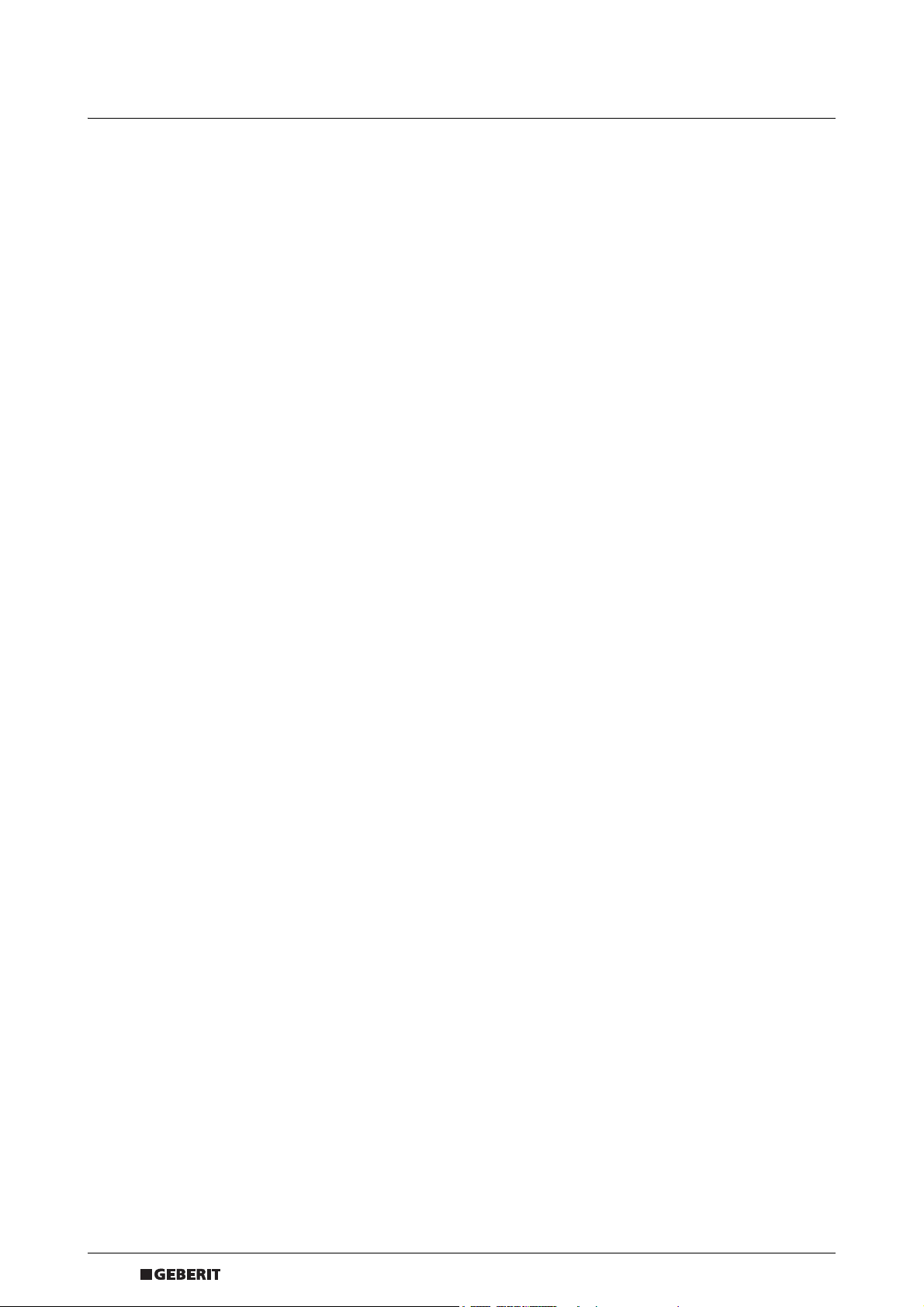
3 Fasten the new cover with the three screws.
Start with the middle screw to center the
cover.
3 Disconnect the remote control cable
connectors and remove the remote control
cable.
Art. no. of new remote control cable:
• 242.947.00.1
4 Mount the new remote control cable and
connect the remote control cable
connectors.
D68129-001 © 04-2014
966.653.00.0 (00)
5 Mount the electric pack entry cover.
5
EN
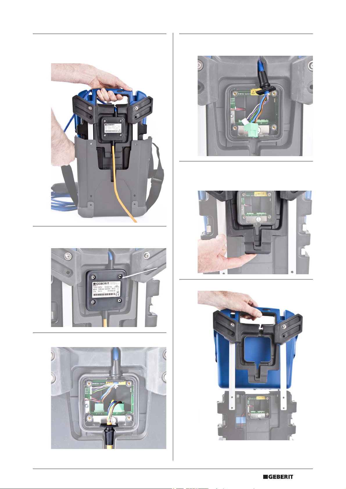
Replacing the mains cable
Disassembling the housing
1 Disconnect the mains plug.
2 Remove the electric pack entry cover.
1 Remove the two lower screws on the upper
tripods and all four screws (M6 x 12 mm) on
the lower tripods.
2 Untighten the eight screws on the inside of
the upper housing section (untight only - do
not remove).
3 Disconnect the mains cable connector and
remove the mains cable.
Art. no. of new mains cable:
• 242.948.P4.1
• 242.948.P0.1
• 242.948.P6.1
• 242.948.P5.1
• 242.948.1P.1
4 Mount the new mains cable and connect the
mains cable connector.
5 Mount the electric pack entry cover.
6
D68129-001 © 04-2014
966.653.00.0 (00)
EN
3 Hold down the lower housing section with
the carrying belt and separate the upper
section from the lower section.
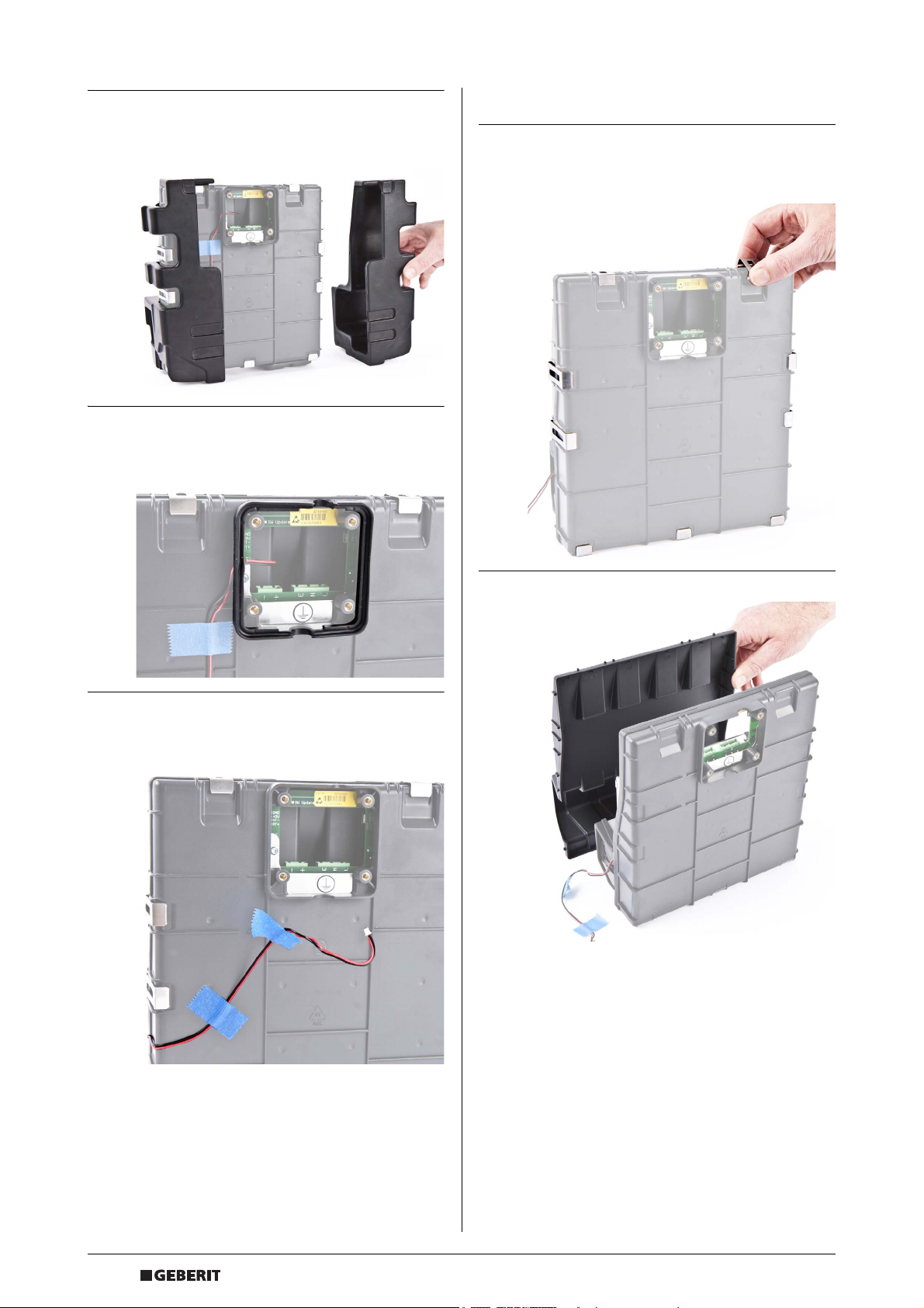
6 Disconnect the remote control cable
connectors.
7 Lift the rubber seal below the electric pack
entry and pull out the electric pack from the
upper housing section.
4 Remove the electric pack entry cover by
removing the four screws (M4 x 10 mm).
5 Disconnect the mains cable connector.
D68129-001 © 04-2014
966.653.00.0 (00)
7
EN
8 Remove left and right protective bumpers to
the sides. Make sure the housing clips do
not fall off.
9 Remove the seal from the electric pack
entry.
Replacing the electric pack seal
1 Remove the housing clips (seven big and
two small clips) and carefully open the
electric pack.
10 Disconnect the fan cable inside the electric
pack entry and remove the tapes from the
electric pack.
8
D68129-001 © 04-2014
966.653.00.0 (00)
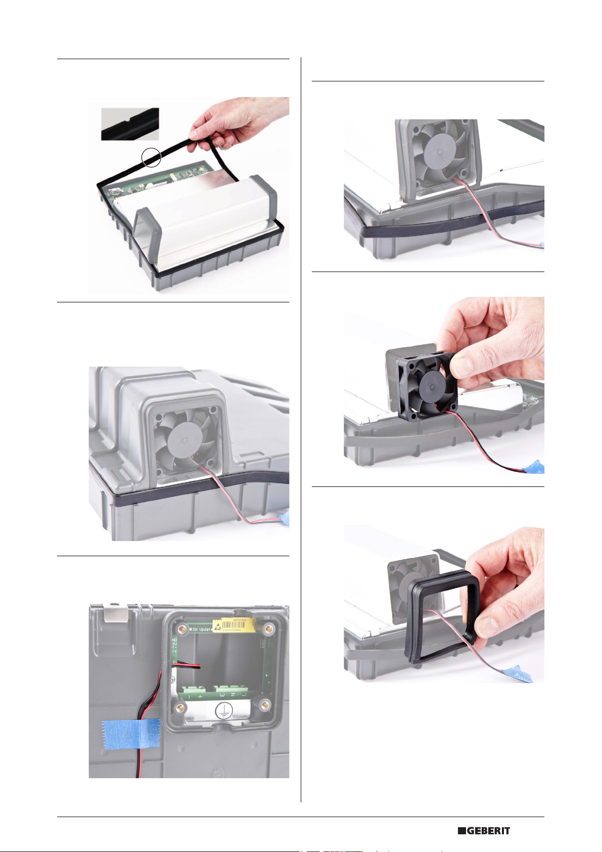
2 Remove the seal and replace it. Ensure that
the notch is at the top.
3 Carefully assemble the housing. Make sure
that the seal fits tight on both sides of the
cooling element.
Add the housing clips to fix the housing.
EN
Replacing the fan
1 Remove the seal on the right and dismount
the fan.
2 Replace the fan.
4 Connect the fan cable and secure the cable
with tape.
3 Hold the fan while mounting the seal right
and left.
D68129-001 © 04-2014
966.653.00.0 (00)
9
 Loading...