

GEA Bock Compressor HG88e
Assembly instructions
HG88e/2735-4 HG88e/2735-4 S HGX88e/2735-4 HGX88e/2735-4 S
HG88e/3235-4 HG88e/3235-4 S HGX88e/3235-4 HGX88e/3235-4 S
D
GB
F
E
I
Ru
96260-11.2014-DGbFEIRu
engineering for a better world GEA Refrigeration Technologies
1

D
GB
F
E
I
Ru
About these instructions
Read these instructions before assembly and before using the compressor. This will avoid misunderstandings and prevent damage. Improper assembly and use of the compressor can result in serious
or fatal injury.
Observe the safety instructions contained in these instructions.
These instructions must be passed onto the end customer along with the unit in which the compressor is installed.
Manufacturer
GEA Bock GmbH
72636 Frickenhausen
Contact
GEA Bock GmbH
Benzstraße 7
72636 Frickenhausen
Germany
Telephone +49 7022 9454 0
Fax +49 7022 9454 137
refrigeration@gea.com
www.gea.com
96260-11.2014-DGbFEIRu
2

Contents Page
1 Safety 4
1.1
1.2 Qualications required of personnel
1.3 General safety instructions
1.4 Intended use
2 Product description 6
2.1 Short description
2.2 Name plate
2.3 Type key
3 Areas of application 8
3.1 Refrigerants
3.2 Oil charge
3.3 Limits of application
4 Compressor assembly 11
4.1 Storage and transport
4.2
4.3 Pipe connections
4.4 Pipes
4.5 Laying suction ans pressure lines
4.6 Operating the shut-off valves
4.7 Operating mode of the lockable service connections
5 Electrical connection 15
5.1 Information for contactor and motor contactor selection
5.2 Standard motor, design for direct or partial winding start
5.3 Basic circuit diagram for partial winding start with standard motor
5.4 Special motor: design for direct or star-delta start
5.5 Circuit diagram for star-delta start 230 V ∆ / 400 V Y
5.6 Electronic trigger unit INT69 G
5.7 Connecting the trigger unit INT69 G
5.8 Functional test of the trigger unit INT69 G
5.9 Oil sump heater (accessories)
6 Commissioning 26
6.1 Preparations for start-up
6.2 Pressure strengh test
6.3 Leak test
6.4 Evacuation
6.5 Refrigerant charge
6.6 Start-up
6.7 Avoid slugging
6.8 Connection of oil level regulator
7 Maintenance 28
7.1 Preparation
7.2 Work to be carried out
7.3 Spare parts recommendation
7.4 Extract from the lubricants table
7.5 Decommissioning
8 Accessories 30
8.1 Capacity regulator
9 Technical data 32
10 Dimensions and connections 34
11 Declaration of conformity and installation 36
96260-11.2014-DGbFEIRu
12 Service 37
Identication of safety instructions
Setting up
D
GB
F
E
I
Ru
3
D
GB
F
E
I
Ru
1| Safety
1.1 Identicationofsafetyinstructions:
DANGER Indicates a dangerous situation which, if not avoided,
will cause immediate fatal or serious injury.
WARNING Indicates a dangerous situation which, if not avoided,
may cause fatal or serious injury.
CAUTION Indicates a dangerous situation which, if not avoided,
may cause fairly severe or minor injury.
ATTENTION Indicates a situation which, if not avoided,
may cause property damage.
INFO Important information or tips on simplifying work.
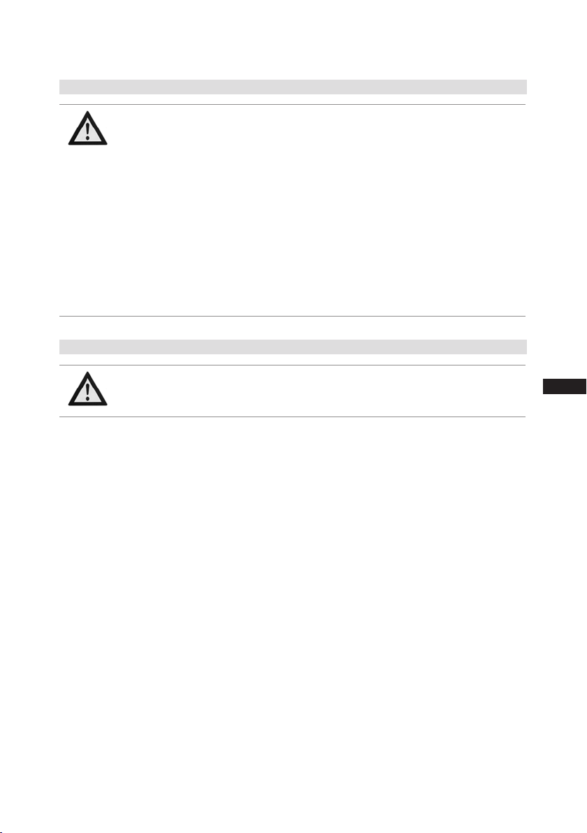
1.2 Qualicationsrequiredofpersonnel
WARNING Inadequately qualied personnel poses the risk of accidents,the
consequencebeing serious or fatalinjury. Work on compressors
istherefore reservedfor personnel which is qualiedtoworkon
pressurized refrigerant systems:
• For example, a refrigeration technician, refrigeration mechatronic
engineer. As well as professions with comparable training, which
enables personnel to assemble, install, maintain and repair refrigeration
and air-conditioning systems. Personnel must be capable of assessing
the work to be carried out and recognising any potential dangers.
96260-11.2014-DGbFEIRu
4
1| Safety
1.3 Safety instructions
WARNING Risk of accidents.
Refrigerating compressors are pressurised machines and as such
call for heightened caution and care in handling.
The maximum permissible overpressure must not be exceeded,
even for testing purposes.
Risk of burns!
- Depending on the operating conditions, surface temperatures of
over 60°C on the discharge side or below 0°C on the suction side
can be reached.
- Avoid contact with refrigerant necessarily.
Contact with refrigerant can cause severe burns and skin
damage.
1.4 Intended use
WARNING The compressor may not be used in potentially explosive
environments!
These assembly instructions describe the standard version of the compressor named in the title
manufactured by GEA Bock. GEA Bock refrigerating compressors are intended for installation in a
machine (within the EU according to the EU Directives 2006/42/EC Machinery Directive, 97/23/EC
Pressure Equipment Directive).
Commissioning is permissible only if the compressor has been installed in accordance with these assembly instructions and the entire system into which it is integrated has been inspected and approved
in accordance with legal regulations.
The compressors are intended for use in refrigeration systems in compliance with the limits of
application.
Only the refrigerant specied in these instructions may be used.
Any other use of the compressor is prohibited!
D
GB
F
E
I
Ru
96260-11.2014-DGbFEIRu
5
2| Product description
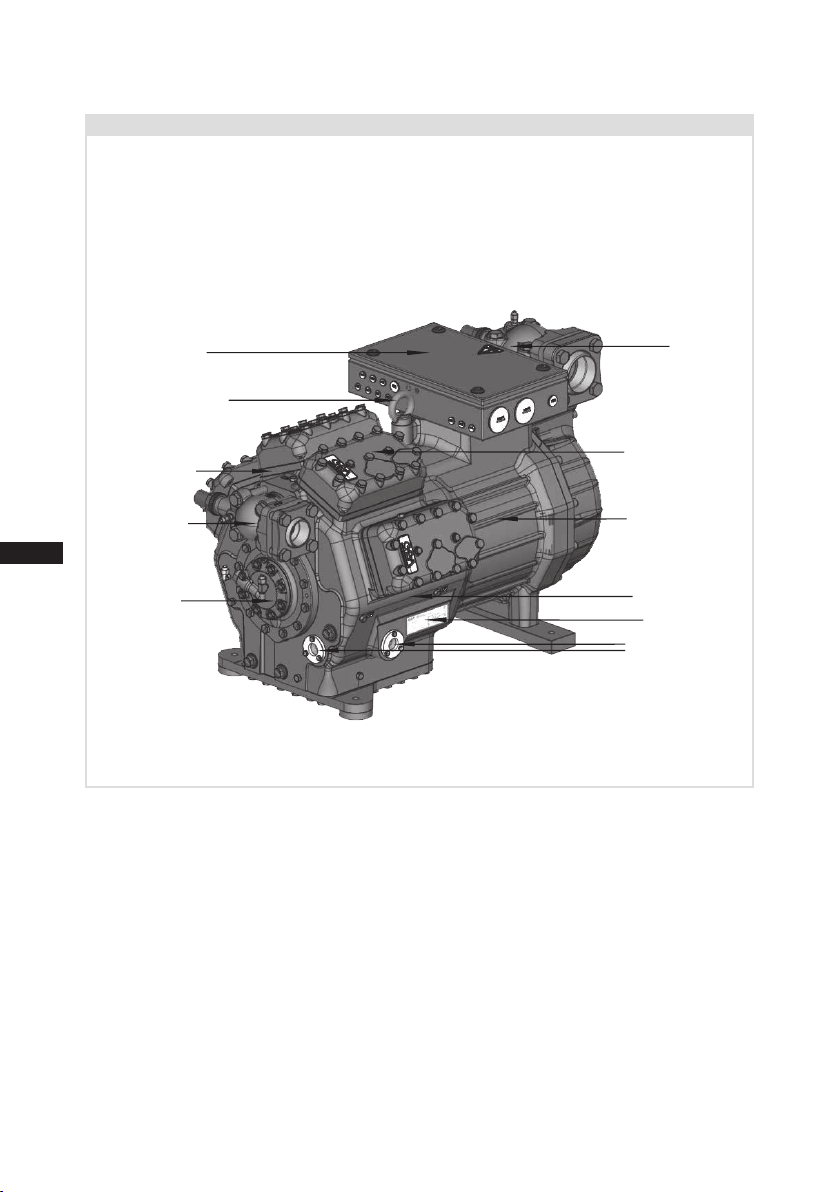
2.1 Short description
• Semi-hermetic eight-cylinder reciprocating compressor with suction-gas cooled drive motor.
• The stream of refrigerant sucked out of the evaporator flows over the motor and cools it
intensively. In this way, the motor can be kept at a relatively low temperature level, particularly
under high loads.
D
GB
F
E
I
Ru
Terminal box
Transport eyelet
Valve plate
Discharge
shut-off valve
Oil pump
Fig. 1
Dimension and connection values can be found in Chapter 10
Suction
shut-off valve
Cylinder cover
Motor section
Drive section
Name plate
Oil sight glass
96260-11.2014-DGbFEIRu
6
2| Product description
2
3
4
5
8
9
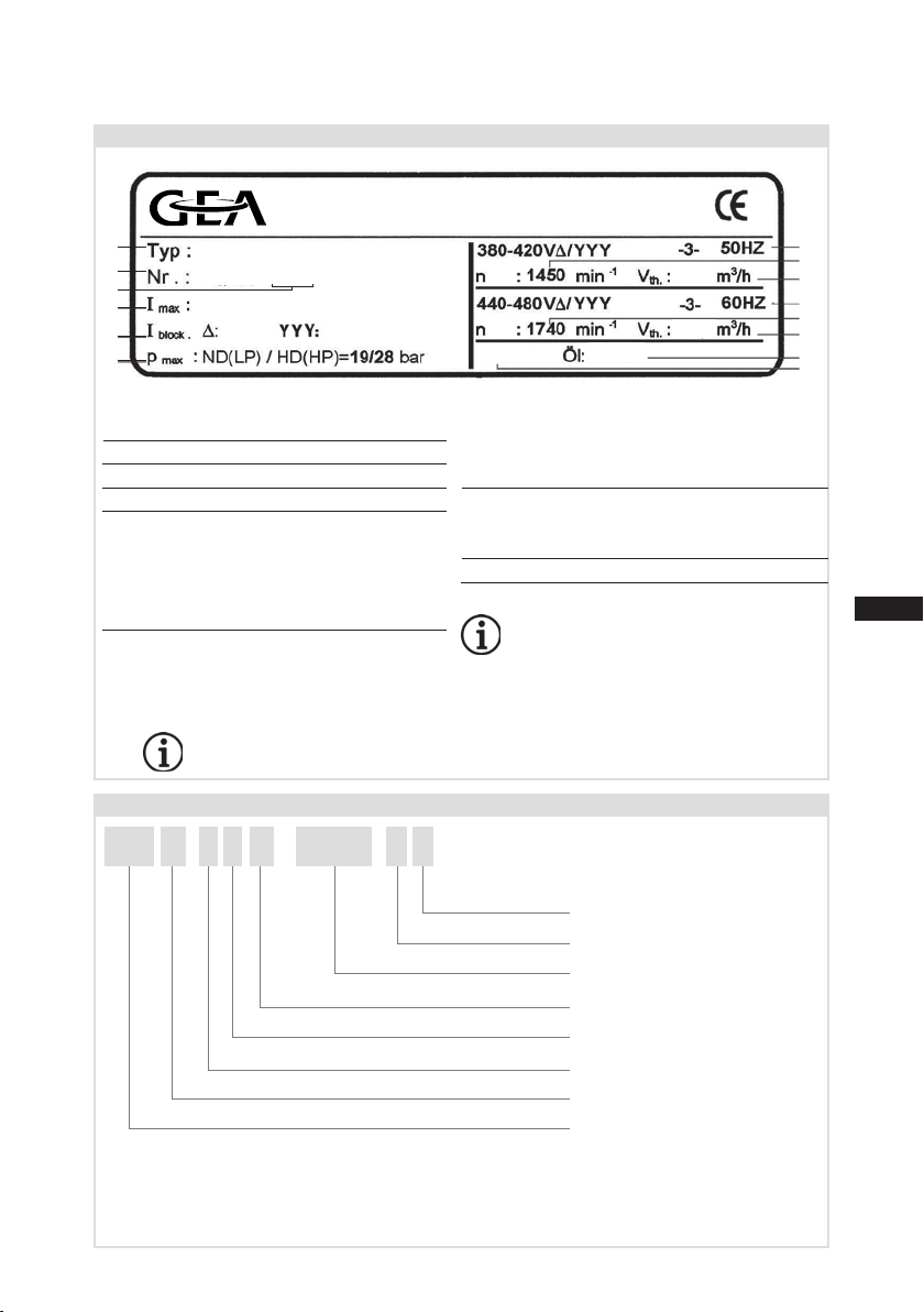
2.2 Name plate (example)
GEA Bock GmbH
72636 Frickenhausen, Germany
1
6
1 Type designation
2 Machine number
3 Type code
4 Maximum operating current
5 Starting current (rotor blocked)
∆: Part winding 1
YYY: Part windings 1 and 2
Y: Part winding 1
YY: Part windings 1 and 2
6 ND (LP): max. admissible over pressure
HD (HP): max. admissible over pressure
HGX88e/3235-4
AW09529A044
135,0 A
475A
Fig. 2
Low pressure side
High pressure side
Observe the limits of
application diagrams!
551A
until A044
}
from A047
}
281
338
IP 65
7 Voltage, circuit, frequency
8 Nominal rotation speed
9 Displacement
10 Voltage, circuit, frequency
11 Nominal rotation speed
12 Displacement
13 Oil type lled at the factory
14 Terminal box protection type
Electrical accessories can
changethe IP protection class!
SE 55
50 Hz
}
60 Hz
}
10
11
12
13
14
D
GB
F
E
I
Ru
2.3 Type key (example)
HG 88 e
¹
²
96260-11.2014-DGbFEIRu
3)
3235-
/
)
HG - Hermetic Gas-Cooled (suction gas-cooled) for the normal- / air conditioning applications
)
X - Ester oil charge (HFC refrigerant, e.g. R134a, R404A/R507, R407C, R407F)
S - More powerful motor, e.g. for air-conditioning applications
4 SX
Motor variant
Number of poles
Swept volume
e-series
Numbers of cylinders
Size
Oil charge ²
Series ¹
3)
)
)
7
3| Areas of application
3.1 Refrigerants
• HFKW / HFC: R134a, R404A/R507, R407C, R407F
• (H)FCKW / (H)CFC: R22
3.2 Oil charge
The compressors are lled at the factory with the following oil type:
- for R134a, R404A/R507, R407C, R407F FUCHS Reniso Triton SE 55
- for R22 FUCHS Reniso SP 46
Compressors with ester oil charge (FUCHS Reniso Triton SE 55) are marked with an X in the type
designation (e.g. HGX88e/3235-4).
INFO
For refilling, we recommend the above oil types.
Alternatives: see lubricants table, Chapter 7.4.
D
GB
F
E
I
Ru
3.3 Limits of application
8
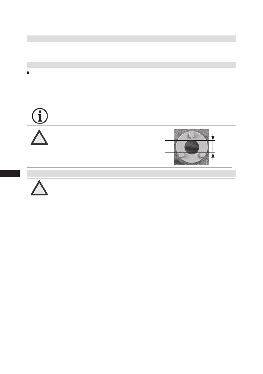
ATTENTION The oil level must be in the
visible part of the sight
glass; damage to the compressor is possible if overfilled or underfilled!
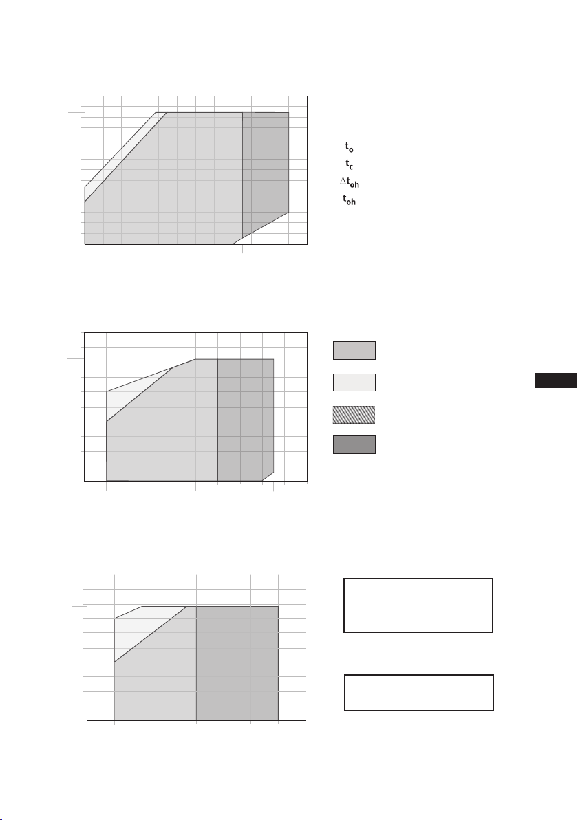
ATTENTION Compressor operation is possible within the operating limits
showninthediagrams.Pleasenotethesignicance
of the shaded areas. Thresholds should not be selected as
design or continuous operation points.
- Permissible ambient temperature (-20°C) - (+60°C)
- Max. permissible discharge end temperature 140°C.
-Max.permissibleswitchingfrequency12x/h.
- A minimum running time of 3 min. steady-state condition
(continuous operation) must be achieved.
For operation with supplementary cooling:
- Use only oils with high thermal stability.
- Avoid continuous operation near the threshold.
- Additional fans (accessories) can be used for additional cooling.
For operation with capacity regulator:
- The suction gas superheat temperature may need to be reduced
or set individually when operating near to the threshold.
- The limits of application are reduced.
Foroperationwithfrequencyconverter:
- The maximum current and power consumption must not be
exceeded.Inthecaseofoperationabovethemainsfrequency,the
application limit can therefore be limited.
When operating in the vacuum range, there is a danger of air
entering on the suction side. This can cause chemical reactions,
a pressure rise in the condenser and an elevated compressed-gas
temperature. Prevent the ingress of air at all costs!
max.
oil level
min.
~
~
Fig. 3
3,0 Ltr.
96260-11.2014-DGbFEIRu
3| Areas of application
-5 12,5
-25
R407C
20
10
0
-10
-20
-30
20
30
40
50
60
70
t (°C)
o
t (°C)
c
61
-5 12,5
-25
?t
Oh
<20K
t +20°C
Oh
R407C
R407F
t (°C)
EGD HG88e
R134a
10
0
-10
-20
-30
20
30
40
50
60
70
t (°C)
c
61
-5 12,5
-25
?t
Oh
<20K
t +20°C
Oh
R407C
c
90
82
80
70
60
50
40
30
20
-30
Fig. 4
t (°C)
c
70
61
60
50
40
30
20
-30
Fig. 5
t (°C)
c
70
60
59
50
40
30
20
-25 -10 -5
Fig. 6
96260-11.2014-DGbFEIRu
<20K
Oh
?t
t +20°C
-20 -10 100 20
?t
<20K
Oh
t +20°C
Oh
-20
<20K
?t
oh
t +20°C
oh
-20
-15
R134a
Oh
R407C
-10
R407F
0
0
12,5
10
5 10 15
25
Evaporation temperature (°C)
Condensing temperature (°C)
Suction gas superheat (K)
Suction gas temperature (°C)
30
t (°C)
o
Unlimited application range
Supplementary cooling or
reduced suction gas temperature
Supplementary cooling and
reduced suction gas temperature
Motor version S
(more powerful motor)
D
GB
F
E
I
Ru
20
t (°C)
o
Maximum admissible
operating pressure (g)
(LP/HP): 19/28 bar
1)
LP = Low pressure
HP = High pressure
Design for other
areasonrequest
9
t (°C)
o
30
40
60
80
90
-20 -10 100 20
30
t (°C)
o
t (°C)
c
82
-30
50
70
12,5
25
?t
Oh
<20K
20
t +20°C
Oh
EGD HG88e
R134a
10
0
-10
-20
-30
20
30
40
50
60
70
t (°C)
c
61
-5 12,5
-25
?t
Oh
<20K
t +20°C
Oh
R407C
R22
R407F
20
30
40
50
60
70
t (°C)
c
59
?t
oh
<20K
t +20°C
oh
-20
-15
-25 -10 -5
0
5 10 15
30
40
60
80
90
-20 -10 100 20
30
t (°C)
o
t (°C)
c
82
-30
50
70
12,5
25
?t
Oh
<20K
20
t +20°C
Oh
R134a
10
0
-10
-20
-30
20
30
40
50
60
70
t (°C)
c
61
-5 12,5
-25
?t
Oh
<20K
t +20°C
Oh
R407C
20
10
0
-10
-20
-30
-40
20
30
40
50
60
70
t (°C)
o
t (°C)
c
66
-35
t +20°C
oh
-5 12,5
?toh<20K
R22
R407F
R404A/R507
20
30
40
50
60
70
t (°C)
c
59
?t
oh
<20K
t +20°C
oh
-20
-15
-25 -10 -5
0
5 10 15
3| Areas of application
t (°C)
c
70
66
60
50
40
?toh<20K
30
20
-40
-35
-30
Fig. 7
t (°C)
D
GB
F
E
I
Ru
10
c
70
60
58
50
40
? toh<20K
30
Fig. 8
-40
20
-50
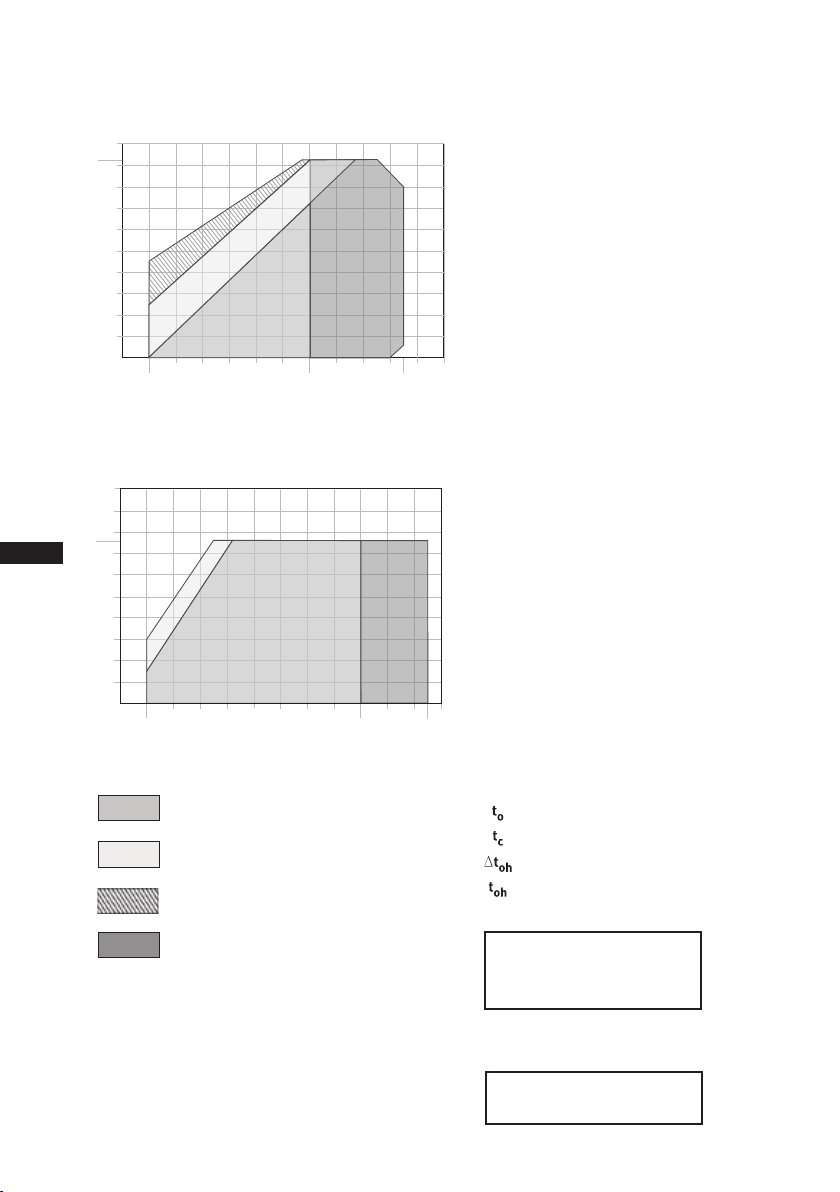
Unlimited application range
Supplementary cooling or
reduced suction gas temperature
Supplementary cooling and
reduced suction gas temperature
Motor version S
(more powerful motor)
R22
t +20°C
oh
-10
-20
0
-5 12,5
R404A/R507
t +20°C
oh
-20
-30
-10
t (°C)
o
20
10
0
10
7,5-45
-5
t (°C)
o
Evaporation temperature (°C)
Condensing temperature (°C)
Suction gas superheat (K)
Suction gas temperature (°C)
Maximum admissible
operating pressure (g)
(LP/HP): 19/28 bar
1)
LP = Low pressure
HP = High pressure
Design for other
areasonrequest
96260-11.2014-DGbFEIRu
4| Compressor assembly
F
E
1
2
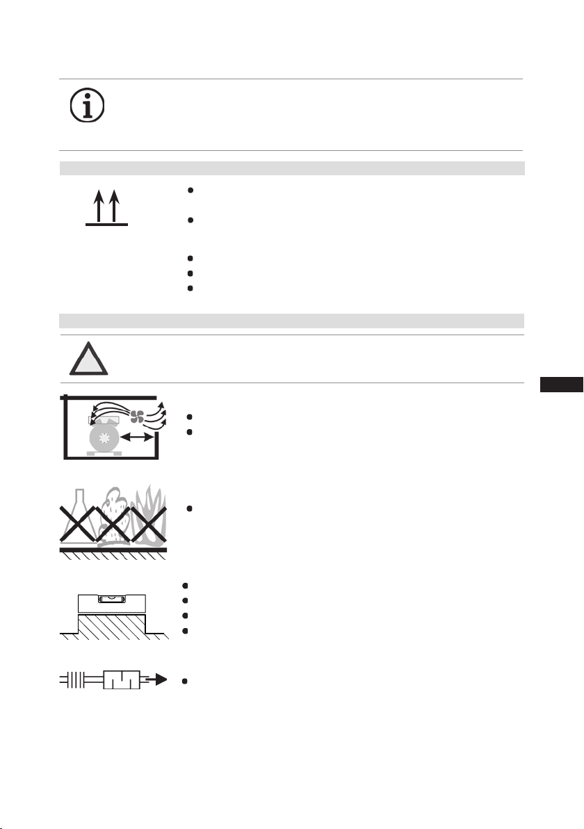
INFO Newcompressorsarefactory-lledwithinertgas(3barnitrogen).
Leave this service charge in the compressor for as long as possible
and prevent the ingress of air. Check the compressor for transport
damage before starting any work.
4.1 Storage and transport
Storage at (-30°C) - (+70°C), maximum permissible relative humidity
10% - 95%, no condensation
Do not store in a corrosive, dusty, vaporous atmosphere or in a com-
?
Fig. 9
Fig. 10
4.2 Setting up
ATTENTION Attachments (e.g. pipe holders, additional units, fastening parts,
Fig. 11
bustible environment.
Use transport eyelet.
Do not lift manually!
Use lifting gear!
etc.) directly to the compressor are not permissible!
Provide adequate clearance for maintenance work.
Ensure adequate compressor ventilation.
D
GB
F
E
I
Ru
Fig. 12
Fig. 13
Fig. 14
96260-11.2014-DGbFEIRu
Do not use in a corrosive, dusty, damp atmosphere or a com-
bustible environment.
Setup on an even surface or frame with sufcient load-bearing capacity.
Single compressor preferably on vibration damper.
Duplex and parallel circuits always rigid.
On shell and tube condensers, install only with rubber-metal shock
mountings.
Installation of pipe vibration mufers is recommended!
11
D
GB
F
E
I
Ru
4| Compressor assembly
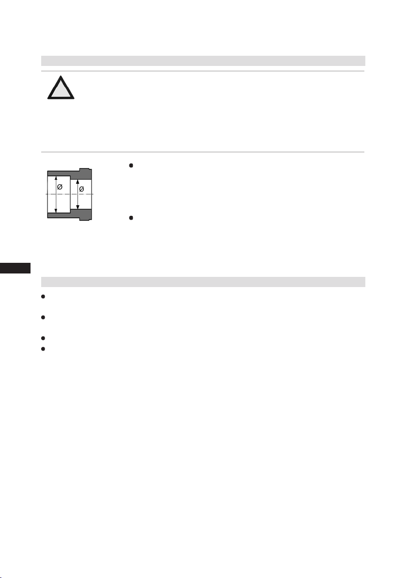
4.3 Pipe connections
ATTENTION Damage possible.
Superheating can damage the valve.
Remove the pipe supports from the valve for soldering.
Only solder using inert gas to inhibit oxidation products (scale).
The discharge gas connection can be moved upwards with an
adapter (accessory). This makes it easier to remove the
compressor from a refrigerating system.
Pipe connections on the compressor are available for soldering or
welding (accessories). The discharge and suction line valves
have graduated inside diameters so that pipes with standart millimetre and inch dimensions can be used. The pipe will be immersed
more or less deeply according to dimension.
The connection diameters of the shut-off valves are rated for maxi-
Fig. 15: graduated
internal diameter
4.4 Pipes
Pipes and system components must be clean and dry inside and free of scale, swarf and layers of
rust and phosphate. Only use air-tight parts.
Lay pipes correctly. Suitable vibration compensators must be provided to prevent pipes being
cracked and broken by severe vibrations.
Ensure a proper oil return.
Keep pressure losses to an absolute minimum.
mum compressor output. Theactualrequiredpipecrosssection
must be matched to the output. The same applies for non-return
valves.
12
96260-11.2014-DGbFEIRu

4| Compressor assembly
4.5 Laying suction and pressure lines
ATTENTION Improperly installed pipes can cause cracks and tears, the result
being a loss of refrigerant.
INFO Proper layout of the suction and discharge lines directly after
the compressor is integral to the system’s smooth running and
vibration behaviour.
A rule of thumb: Always lay the rst pipe section starting from the shut-off valve downwards
and parallel to the drive shaft.
Rigid
fixed point
As short as
possible
Fig. 16
D
GB
F
E
I
Ru
96260-11.2014-DGbFEIRu
13

4| Compressor assembly
4.6 Operating the shut-off valves
Before opening or closing the shut-off valve, release the valve spindle seal by approx. ¼ of a turn
counter-clockwise.
After activating the shut-off valve, re-tighten the adjustable valve spindle seal clockwise.
Release
Tighten
Valve spindle seal
Fig. 17
4.7 Operating mode of the lockable service connections
Fig. 18
D
GB
F
E
I
Ru
Service connec
tion closed
Spindle
-
Connection
blocked
Opening the shut-off valve:
Spindle: turn to the left (counter-clockwise) as far as it will go.
—> Shut-off valve completely opened / service connection closed.
Service connec
tion opened
Spindle
-
Connection
open
Opening the service connection
Spindle: Turn ½ - 1 turn clockwise.
—> Service connection opened / shut-off valve opened.
Compressor
Compressor
Pipe connection
Fig. 19
Pipe connection
Fig. 20
14
96260-11.2014-DGbFEIRu

5| Electrical connection
5 Electrical connection
DANGER Risk of electric shock! High voltage!
Only carry out work when the electrical system is disconnected
from the power supply!
INFO
5.1 Information for contactor and motor contactor selection
All protection devices and switching or monitoring units must be tted in accordance with the local
safety regulations and established specications (e.g. VDE) as well as with the manufacturer’s infor-
mation. Motor protection switches are required! Motor contactors, feed lines, fuses and motor
protection switches must be rated on the basis of the maximum working current (see name plate).
For motor protection use a current-dependent and time-delayed overload protection device for monitoring all three phases. Set the overload protection device so that it must be actuated within 2 hours,
if there is 1.2 times the max. working current.
Connect the compressor motor in accordance with the circuit diagram
(see inside of terminal box).
Use suitable cable entry point of the correct protection type (see
name plate) for routing cables into the terminal box. Insert the strain
reliefs and prevent chafe marks on the cables.
Compare the voltage and frequency values with the data for the
mains power supply.
Only connect the motor if these values are the same.
D
GB
F
E
I
Ru
96260-11.2014-DGbFEIRu
15

5| Electrical connection
5.2 Standard motor, design for direct or partial winding start
Designation on the name plate Sticker on the terminal box
until A044 from A047 until A044 from A047
∆/YYY Y/YY
Y/ YY
Compressors with this marking are suitable for direct or partial winding start. The motor winding is
subdivided into two parts:
Until type code A044: Part winding 1 = 60% and part winding 2 = 40%. This winding division
reduces the start-up current needed for a part winding start to approx. 65% of that for a direct start.
From type code A047: Part winding 1 = 50% and part winding 2 = 50%. This winding division
reduces the start-up current needed for a part winding start to approx. 50% of that for a direct start.
D
GB
F
E
I
Ru
INFO
A mechanical unloaded start with bypass solenoid valve is
notrequired.
16
96260-11.2014-DGbFEIRu

Gelber Aufkleber
am Klemmenkasten
∆/YYY
Typschildangabe
Gelber Aufkleber
am Klemmenkasten
5| Electrical connection
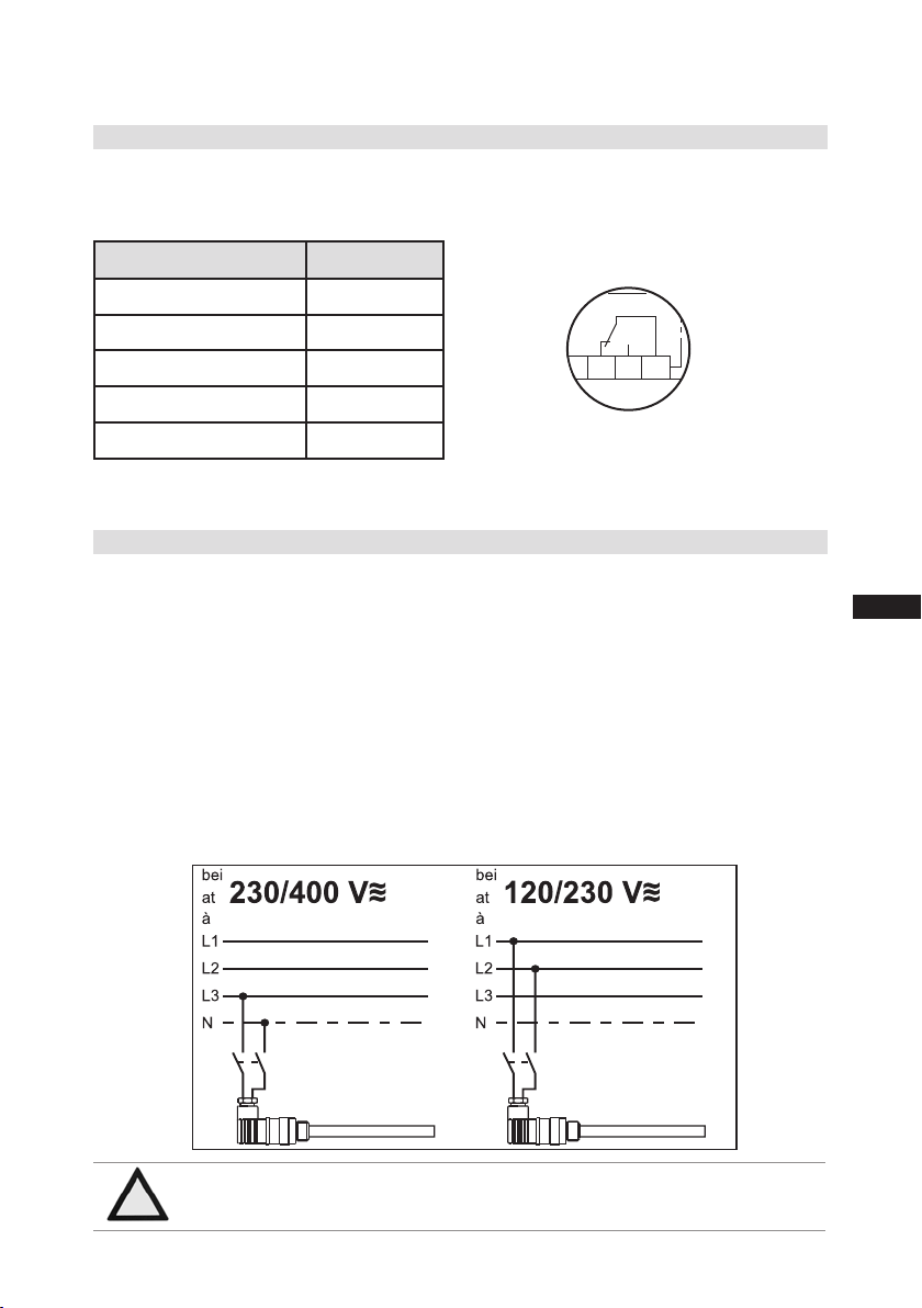
The motor is wired for direct start (Y YY resp. YY) at the factory. For part winding start ∆ / YYY
resp. Y/YY the bridges must be removed and the motor feed line connected according to the
circuit diagram:
400 V
Direct start Part winding start
ATTENTION Failure to do this results in opposed rotary elds and results in
damage to the motor. After the motor starts up via partial winding
1, partial winding 2 must be switched on after a maximum delay
of one second. Failure to comply can adversely affect the service
life of the motor.
INFO When testing coils with resistance tester, please note that partial
winding 1 and partial winding 2 are wired internally in HG88e.
D
GB
F
E
I
Ru
96260-11.2014-DGbFEIRu
17

5.3 Basic circuit diagram for part winding start with standart motor
5 6 7
D
GB
F
E
I
Ru
QA1
0
X SS
L1 L2 L3 N PE
FC1.1
I=66%
60%
QA2
1
I>
I>
I>
1
3
5
2
4
6
1
2
3
1U1
1V1
1W1
2
FC1.2
I=33%
40%
PE
EC1
M
/YYY
BT1
QA3
2U1
2V1
2W1
I>
I>
1
3
2
4
4
5
I>
5
6
6 7
3
FC1.1
FC1.2
OG OG
SF1
L N
FC2
4
4A
8
10
11 12 14
INT69
11
18
Compressor terminal box
Anschlußkasten Verdichter
Fig. 21
BP1 Oil differential pressure monitor
BP2 High pressure safety monitor
BP3
Safety chain (high/low pressure monitoring)
BT3 Release switch (thermostat)
BT1 Cold conductor (PTC sensor) motor winding
BT2.X Thermal protection thermostat
EB1 Oil sump heater
EC1 Compressor motor
FC1.1 Motor protection switch (part winding 1)
BT2
BT2
BT29BT2
96260-11.2014-DGbFEIRu

5 6 7
8
9
L1.1
L2.1
L3.1
L1.2
QA2
12T213N14L15M16
BP1
P-Öl
17 18 19
QA2
KF1
QA2
QA3
20
KF1
21 22
23 24
QA2
N
PE
25
26
D
GB
S
P>
BP2
BP3
P
BT3
EB1
F
E
I
Ru
FC1.2 Motor protection switch (part winding 2)
FC2 Control power circuit fuse
KF1 Delay relay max. 1s
QA1 Main switch
QA2 Mains contactor (part winding 1)
QA3 Mains contactor (part winding 2)
SF1 Control voltage switch
XSS Terminal strip in the external switch cabinet
96260-11.2014-DGbFEIRu
19

D
GB
F
E
I
Ru
5| Electrical connection
5.4 Special motor: design for direct or star-delta start
Amechanicalunloadedstartwithbypasssolenoidvalve(accessories)isrequiredforthe
star-delta start.
Designation on the name plate Sticker on the terminal box
∆ / Y
20
96260-11.2014-DGbFEIRu

5| Electrical connection
Star-delta start-up is only possible for ∆ (230 V) power supply. Example:
230 V Δ
Direct start Star-delta-start
In the factory the motor is wired for direct starting at high voltage.
The brides are to be removed for star delta starting at low voltage.
400 V Y
Direct start only
D
GB
F
E
I
Ru
96260-11.2014-DGbFEIRu
21

5 6 7
BP1
QA2
5.5 Circuit diagram for star-delta start 230 V ∆ / 400 V Y
D
GB
F
E
I
Ru
QA1
0
X SS
L1 L2 L3 N PE
FC1.1
QA2
1
I>
I>
I>
1
3
5
QA4
2
1
Y
4
6
2
3
U1
V1
W1
2
FC1.2
I>
I>
1
345
2
PE
EC1
M
3
˜
BT1
1
QA3
6
3
2
4
4
W2
U2
V2
5
I>
5
6
6 7
3
FC1.1
FC1.2
SF1
L N
FC2
4
4A
8
9 10 11
11 12 14
INT69
22
Anschlußkasten Verdichter
Compressor terminal box
Fig. 22
BP1 Oil differential pressure monitor
BP2 High pressure safety monitor
BT2.X Thermal protection thermostat
BP3
Safety chain (high/low pressure monitoring)
BT3 Release switch (thermostat)
EB1 Oil sump heater
EC1
FC1.1
FC1.2
Compressor motor
Motor protection switch (mains contactor)
Motor protection switch ( Δ-contactor)
BT2
BT2 BT2BT2
96260-11.2014-DGbFEIRu

5 6 7
QA2
QA2
QA4
KF4
QA4
QA3
KF4
8
QA2
9
L1.1
L2.1
L3.1
L1.2
12T213N14L15M16
BP1
P-Öl
FC2 Control power circuit fuse
KF4 Delay relay for contactor switch over
QA1 Main switch
QA2 Mains contactor
QA3 Δ-contactor
QA4 Y-contactor
SF1 Control voltage switch
XSS Terminal strip in the external switch cabinet
QA2
17
QA3
QA4
18
19
20
21 22
KF4
23 24
N
PE
25
26
D
GB
S
P>
BP2
BP3
P
BT3
EB1
F
E
I
Ru
96260-11.2014-DGbFEIRu
23

5| Electrical connection
5.6 Electronic trigger unit INT69 G
The compressor motor is tted with cold conductor temperature sensors (PTC) connected to the
electronic trigger unit INT69 G in the terminal box. In case of excess temperature in the motor
winding, the INT 69 G deactivates the motor contactor. Once cooled, it can be restarted only if the
electronic lock of the output relay (terminals B1+B2) is released by interrupting the supply voltage.
The hot gas side of the compressor can also be protected against overtemperature using thermal
protection thermostats (accessory).
The unit trips when an overload or inadmissible operating conditions occur. Find and remedy
the cause.
INFO Therelay switching output is executed asa oating changeover
contact.Thiselectricalcircuitoperatesaccordingtothequiescent
current principle, i.e. the relay drops into a the idle position and
deactivates the motor contactor even in case of a sensor break or
open circuit.
D
GB
F
E
I
Ru
5.7 Connection of the trigger unit INT69 G
INFO Connect the trigger unit INT69 G in accordance with the circuit dia-
gram. Protect the trigger unit with a delayed-action fuse (F) of max.
4 A. In order to guarantee the protection function, install the trigger
unitastherstelementinthecontrolpowercircuit.
ATTENTION
PTC cable on the trigger unit
INT69 G and terminals PTC 1 and
PTC 2 on the compressor terminal board must not come into
contact with mains voltage.
This would destroy the trigger
unit INT69 G and PTC sensors.
PTC
PTC1
Abb. 23
Terminal box
Motor Protection INT69 G
NL B1 B2 12 14 11
Lock out
supply
PTC2
24
96260-11.2014-DGbFEIRu
5| Electrical connection
Anschlussschema für Ölsumpfheizung
Connection diagramm for oil sump heater
Plan de raccordement pour résistance de carter d‘huile
5.8 Function test of the trigger unit INT69 G
Before commissioning, after troubleshooting or making changes to the control power circuit, check
the functionality of the trigger unit. Perform this check using a continuity tester or gauge.
Gauge state Relay position
Deactivated state 11-12
INT69 G switch-on 11-14
Remove PTC connector 11-12
Insert PTC connector 11-12
Reset after mains on 11-14
5.9 Oil sump heater (accessories)
When the compressor is at a standstill, refrigerant diffuses into the lubricating oil of the compressors
housing, depending on pressure and ambient temperature. This reduces the lubricating capacity of
the oil. When the compressor starts up, the refrigerant contained in the oil evaporates out throught the
reduction in pressure. The consequences can be foaming and migration of the oil, causing oil shocks
under certain circumstances.
Operation: The oil sump heater operates when the compressor is at a standstill. When the compressor starts up, the oil sump heater switches off again automatically.
Connection: The oil sump heater must be connected via an auxiliary contact (or parallel wired auxiliary contact) of the compressor contactor to a seperate electric circuit.
El. data: 230 V - 1 - 50/60 Hz, 200 W.
Relay position INT69 G
B2 12 14 11
Fig. 24
D
GB
F
E
I
Ru
ATTENTION Connection to the current path of the safety control chain is not
96260-11.2014-DGbFEIRu
permitted.
Fig. 25
25

6| Commissioning
6.1 Preparations for start-up
D
GB
F
E
I
Ru
INFO
The compressor has undergone trials in the factory and all functions have been tested. There are
therefore no special running-in instructions.
Check the compressor for transport damage!
6.2 Pressure strength test
DANGER Risk of bursting!
The compressor has been factory-tested for pressure resistance. The following must be observed if
the entire plant is subjected to an additional pressure strength test:
Test the refrigeration circuit according to EN 378-2 or a corresponding safety standard.
6.3 Leak test
DANGER Risk of bursting!
Carry out the leak test of the refrigerating system in accordance with EN 378-2 or a corresponding
safety standard without including the compressor.
To protect the compressor against inadmissible operating conditions,
high pressure and low pressure pressostats are mandatory on the
installation side.
The compressor must only be pressurised using nitrogen (N2).
Never pressurise with oxygen or other gases!
The maximum permissible overpressure of the compressor must
not be exceeded at any time during the testing process (see name
plate data)! Do not mix any refrigerant with the nitrogen as this
could cause the ignition limit to shift into the critical range.
Do not mix any refrigerant with the nitrogen (N2) as this could cause the ignition limit to shift into the critical range.
26
6.4 Evacuation
ATTENTION Do not start the compressor if it is under vacuum. Do not apply
any voltage - even for test purposes (must only be operated with
refrigerant).
Under vacuum, the spark-over and creepage current distances of the
terminal board connection bolts shorten; this can result in winding and
terminal board damage.
First evacuate the system and then include the compressor in the evacuation process.
Relieve the compressor pressure.
Open the suction and pressure line shut-off valves.
Evacuate the suction and discharge pressure sides using the vacuum pump.
At the end of the evacuation process, the vacuum should be < 1.5 mbar when the pump is switched off.
Repeat this process as often as is required.
96260-11.2014-DGbFEIRu

6| Commissioning
6.5 Refrigerantlling
CAUTION Wear personal protective clothing such as goggles and protective
gloves!
Make sure that the suction and pressure line shut-off valves are open.
With the compressor switched off, add the liquid refrigerant directly to the condenser or receiver,
breaking the vacuum.
If the refrigerant needs topping up after starting the compressor, it can be topped up in vapour
form on the suction side, or, taking suitable precautions, also in liquid form at the inlet to the
evaporator.
ATTENTION Avoidoverllingthesystemwithrefrigerant!
To avoid shifts in concentration, zeotropic refrigerant blends must
alwaysonlybelledintotherefrigeratingplantinliquidform.
Donotpourliquidcoolantthroughthesuctionlinevalveon
the compressor.
It is not permissible to mix additives with the oil and
refrigerant.
6.6 Start-up
WARNING Ensure that both shut-off valves are open before starting the
compressor!
Check that the safety and protection devices (pressure switch, motor protection, electrical
contact protection measures, etc.) are all functioning properly.
Switch on the compressor and allow to run for a minimum of 10 min.
Check the oil level by: The oil must be visible in the sightglass.
D
GB
F
E
I
Ru
ATTENTION Iflargerquantitiesofoilhavetobetoppedup,thereisariskof
oil hammer effects.
If this is the case check the oil return!
6.7 Avoiding slugging
ATTENTION Slugging can damage the compressor and cause refrigerant to
leak.
To prevent slugging:
The complete refrigeration system must be properly designed.
All components must be compatibly rated with each other with regard to output
(particularly the evaporator and expansion valves).
Suction gas superheat at the compressor input should be min. 7 - 10 K. (check the setting
of the expansion valve).
The system must reach a state of equilibrium.
Particularly in critical systems (e.g. several evaporator points), measures are recommended such
as replacement of liquid traps, solenoid valve in the liquid line, etc.
96260-11.2014-DGbFEIRu
There should be no movement of coolant whatsoever while the compressor is at a standstill.
27

D
124
GB
F
E
I
Ru
6| Commissioning
6.8 Connection of oil level regulator
Oil level regulation systems have proven themselves with parallel circuits of several compressors.
The connection "0" is provided for installing an oil level regulator (see dimensions drawing). All
common oil level regulators from AC&R, ESK and Carly as well as the OM3 TraxOil oil level regulation
system from Alco can be connected directly without adapters (see Fig. 25). A sight glass on the oil
level regulator is not required.
o
124
47,6
124
o
o
M6 x 10
je 3 mal
3 times each
Mechanical oil level regulator
at the "O" connection
Fig. 26
o
124
3 hole connection diagramm for
3-Loch-Anschlussbild für ESK,
ESK, AC&R and CARLY
AC&R und CARLY
3-Loch-Anschlussbild für TraxOil
3 hole diagramm for TraxOil
7| Maintenance
7.1 Preparation
WARNING Before starting any work on the compressor:
Switch off the compressor and secure it to prevent a restart.
Relieve compressor of system pressure.
Preventairfrominltratingthesystem!
After maintenance has been performed:
Connect safety switch.
Evacuate compressor.
Release switch lock.
7.2 Work to be carried out
In order to guarantee optimum operational reliability and service life of the compressor, we recommend
carrying out servicing and inspection work at regular intervals:
Oil change:
- not mandatory for factory-produced series systems.
- for eld installations or when operating near the application limit: for the rst time after 100
to 200 operating hours, then approx. every 3 years or 10,000 - 12,000 operating hours.
Dispose of used oil according to the regulations; observe national regulations.
Annual checks: Oil level, leak tightness, running noises, pressures, temperatures, function of
auxiliary devices such as oil sump heater, pressure switch.
28
96260-11.2014-DGbFEIRu

7| Maintenance
7.3 Recommended spare parts
HG88e / ...
Designation
Set of gaskets kit 81007
Valve plate kit 81040 81041
Oil pump kit 80116
Oil sump heater kit (220-240 V ) 80237
Only use genuine GEA Bock spare parts!
7.4 Extract from the lubricants table
The oil type lled as standard in the factory is marked on the name plate . This oil type should be
used as a preference. Alternatives are stated in the extract from our lubricants table below.
Refrigerants GEA Bock standard oil types
HFC
(e.g. R134a, R404A,
R407C, R407F)
HCFC (e.g. R22) Fuchs Reniso SP 46
7.5 Decommissioning
Close the shut-off valves on the compressor. Drain the refrigerant (it must not be discharged into the
environment) and dispose of it according to the regulations. When the compressor is depressurised,
undo the fastening screws of the shut-off valves. Remove the compressor using an appropriate hoist.
Dispose of the oil inside in accordance with the applicable national regulations.
Fuchs Reniso Triton SE 55
2735-4 (S) 3235-4 (S)
Item No. Item No.
Recommended alternatives
Fuchs Reniso Triton SEZ 32
Esso/Mobil EAL Arctic 46
Sunoco Suniso SL 46
Texaco Capella HFC 55
Fuchs Reniso SP 32
BP Energol LPT 46
Sunoco Suniso 3,5 GS
Texaco Capella WF 46
D
GB
F
E
I
Ru
96260-11.2014-DGbFEIRu
29

D
GB
F
E
I
Ru
8| Accessories
8.1 Capacity regulator
ATTENTION If the capacity regulator is installed at the factory, the control com-
LR 1 LR 2
LR 3
Fig. 27
ponent(pilotvalve)issubsequentlyinstalledandconnectedbythe
customer. If the control component is not connected, the cylinder bank
is switched off permanently. Damage to the compressor is possible!
Cover
Delivery condition (from the factory):
Capacity regulator installed with cover
(transport protection).
Knurled nut
Magnetic coil
Control unit
(pilot valve)
Seal ring
Fig. 28
Fig. 29
Before start-up, remove the cover at the capacity
regulator and replace it with the enclosed control
unit (pilot valve).
Attention! Compressor is under pressure!
Depressurize the compressor first.
WARNING Several capacity regulators cannot switch at the same time during
compressor operation! Otherwise the sudden change in load can
damage the compressor! Comply with the switching interval of 60 s.
• Comply with the switching sequence:
Swiching on LR1 60s LR2 60s LR3
Swiching off LR3 60s LR2 60s LR1
30
Fig. 30
Screw in control unit (pilot valve) with seal
ring and tight with 15 Nm.
Wet thread sides with ester oil.
Insert magnetic coil, fasten it with knurled
nut and connect it.
96260-11.2014-DGbFEIRu

8| Accessories
ATTENTION Capacity-regulated operation alters the gas speeds and pressure
ratios of the refrigerating plant: Adjust the suction line routing and
dimensioning accordingly, do not set the control intervals too close and
do not let the system switch more than 12 times per hour (refriger-
atingplantmusthavereachedastateofequilibrium).Continuous
operation in the control stage is not recommended as the gas
velocity in the plant system under certain circumstances does not
guaranteesufcientoilreturntothecompressorwithactivated
capacity regulator.
We recommend switching to unregulated operation (100% capac-
ity) for at least 5 minutes per capacity-regulated operating hour.
An assured oil return can also be realised by a 100% capacity
requirementaftereachcompressorrestart.
Electrical actuation of the solenoid valve: Normally open, (cor-
responds to 100 % compressor capacity).
Special accessories are only premounted in the factory if ordered specially by customer. Retrotting is
possible in full compliance with the safety instructions and repair instructions enclosed with the kits.
Information about the use, operation, maintenance and servicing of the components is available in the
printed literature or on the internet under www.gea.com
D
GB
F
E
I
Ru
96260-11.2014-DGbFEIRu
31

D
GB
F
E
I
Ru
9| Technical data until A044
Oil charge
) 9,0
4
SV
line
Suction
DV
line
Discharge
current
Starting
(rotor locked)
PW 1 / PW 1 + 2
3
Max.
Electrical data Weight Connections
2
sumption
power con-
2
current
Operating
PW 1 + 2
8
/
1
) 76 (3
8
/
1
54 (2
All specications are based on the average of the voltage range
For solder connections
3
4
32
Voltage Max.
rpm)
50 / 60 Hz
(1450 / 1740
Displacement
No. of cylinders
Type
380-420 V Δ/YYY - 3 - 50 Hz PW
until
1
/h A kW A kg mm (inch) mm (inch) Ltr.
3
m
440-480 V Δ/ Y YY - 3 - 60 Hz PW
A044
PW = Part Winding
Winding ratio : 60% / 40%
237,9 / 285,5 118 63,7 475 / 551 448
HG88e/2735-4
HG88e/2735-4 S 237,9 / 285,5 141 7 7,5 520 / 605 468
8
Tolerance (± 10%) relative to the mean value of the voltage range.
Other voltages and types of current on request.
For 60Hz operation, the specications have to be multiplied by the factor
HG88e/3235-4 281,3 / 337,6 135 74,6 475 / 551 442
HG88e/3235-4 S 281,3 / 337,6 160 91,0 520 / 605 462
1.2. The max. working current remains unchanged.
- The specications for max. power consumption apply for 50Hz operation.
2
1
category AC3
- Take account of the max. operating current / max. power consumption for
design of fuses, supply lines and safety devices. Fuse: Consumption
96260-11.2014-DGbFEIRu

9| Technical data from A047
Oil charge
) 9,0
4
SV
line
Suction
DV
line
Discharge
current
Starting
(rotor locked)
PW 1 / PW 1 + 2
3
Max.
Electrical data Weight Connections
2
sumption
power con-
2
current
Operating
PW 1 + 2
8
/
1
) 76 (3
8
/
1
54 (2
All specications are based on the average of the voltage range
For solder connections
3
4
D
GB
F
E
I
Ru
Voltage Max.
rpm)
50 / 60 Hz
(1450 / 1740
Displacement
No. of cylinders
Type
96260-11.2014-DGbFEIRu
380-420 V Y/YY - 3 - 50 Hz PW
1
from
A047
/h A kW A kg mm (inch) mm (inch) Ltr.
3
m
440-480 V Y/Y Y - 3 - 60 Hz P W
PW = Part Winding
Winding ratio : 50% / 50%
237,9 / 285,5 114 63,7 475 / 551 448
8
HG88e/2735-4
HG88e/2735-4 S 237,9 / 285,5 135 7 7,5 520 / 605 468
HG88e/3235-4 281,3 / 337,6 131 74,6 475 / 551 442
HG88e/3235-4 S 281,3 / 337,6 160 91,0 520 / 605 462
Tolerance (± 10%) relative to the mean value of the voltage range.
Other voltages and types of current on request.
For 60Hz operation, the specications have to be multiplied by the factor
1.2. The max. working current remains unchanged.
- The specications for max. power consumption apply for 50Hz operation.
2
1
category AC3
- Take account of the max. operating current / max. power consumption for
design of fuses, supply lines and safety devices. Fuse: Consumption
33

10| Dimensions and connections
360
(L)* = Brazing connection
(L)* = Lötanschluß
Maße in mm
Änderungen vorbehalten
Massenschwerpunkt
inchConnection oil temperature sensor
Anschluß Ölspiegelregulator
O
inch
Connection thermal protection thermostat
1/8" NPTF
ZollAnschluß Öltemperatursensor
mm
Q
inchConnection oil service valve
7/16" UNF
3xM6
ZollAnschluß Ölserviceventil
ÖV
Connection oil level regulator
mmConnection oil pressure differential sensor
M20x1,5
mmAnschluß Öl-Differenzdrucksensor
P
mm
Anschlüsse / Connections
SV
Saugabsperrventil, Rohr (L)* mm - Zoll
76 - 3 1/8“
Suction line valve, tube (L)* mm - inch
DV
Druckabsperrventil, Rohr
(L)* mm - Zoll
54 - 2 1/8“
Discharge line valve, tube (L)* mm - inch
A
Anschluß Saugseite, nicht absperrbar Zoll
1/8" NPTF
Connection suction side, not lockable inch
A1
Anschluß Saugseite, absperrbar Zoll
7/16" UNF
Connection suction side, lockable inch
A2
Anschluß Saugseite, nicht absperrbar Zoll
1/4" NPTF
Connection suction side, not lockable inch
B
Anschluß Druckseite, nicht absperrbar Zoll
1/8" NPTF
Connection discharge side, not lockable inch
B1
Anschluß Druckseite, absperrbar Zoll
7/16" UNF
Connection discharge side, lockable inch
C
Anschluß Öldrucksicherheitsschalter OIL
Zoll
7/16" UNF
Connection oil pressure safety switch OIL inch
D
Anschluß Öldrucksicherheitsschalter LP Zoll
7/16" UNF
Connection oil pressure safety switch LP inch
D1
Anschluß Ölrückführung vom Ölabscheider Zoll
1/4" NPTF
Connection oil return from oil separator inch
E
Anschluß Öldruckmanometer Zoll
7/16" UNF
Connection oil pressure gauge inch
F
Ölablaß mm
M22x1,5
Oil drain mm
H
Stopfen Ölfüllung mm
M22x1,5
Oil charge plug mm
J
Anschluß Ölsumpfheizung mm
M22x1,5
Connection oil sump heater mm
K
Schauglas -
-
Sight glass -
L
Anschluß Wärmeschutzthermostat Zoll
1/8" NPTF
D1
D
B
B1 A1
L
C
E
H
K,O
Q
ÖV
J
F
P
412
ca.655
430
252
4x 13,5
ca.610
Schwingungsdämpfer
Vibration absorbers
45
F
E
D
1
2
34
5
Anschluß Ölspiegelregulator
O
inch
Connection thermal protection thermostat
mm
inchConnection oil service valve
ZollAnschluß Ölserviceventil
ÖV
Connection oil level regulator
mmConnection oil pressure differential sensor
mmAnschluß Öl-Differenzdrucksensor
P
mm
Anschlüsse / Connections
SV
Saugabsperrventil, Rohr (L)* mm - Zoll
Suction line valve, tube (L)* mm - inch
DV
Druckabsperrventil, Rohr
(L)* mm - Zoll
Discharge line valve, tube (L)* mm - inch
A
Anschluß Saugseite, nicht absperrbar Zoll
Connection suction side, not lockable inch
A1
Anschluß Saugseite, absperrbar Zoll
Connection suction side, lockable inch
A2
Anschluß Saugseite, nicht absperrbar Zoll
Connection suction side, not lockable inch
B
Anschluß Druckseite, nicht absperrbar Zoll
Connection discharge side, not lockable inch
B1
Anschluß Druckseite, absperrbar Zoll
Connection discharge side, lockable inch
C
Anschluß Öldrucksicherheitsschalter OIL
Zoll
Connection oil pressure safety switch OIL inch
D
Anschluß Öldrucksicherheitsschalter LP Zoll
Connection oil pressure safety switch LP inch
D1
Anschluß Ölrückführung vom Ölabscheider Zoll
Connection oil return from oil separator inch
E
Anschluß Öldruckmanometer Zoll
Connection oil pressure gauge inch
F
Ölablaß mm
Oil drain mm
H
Stopfen Ölfüllung mm
Oil charge plug mm
J
Anschluß Ölsumpfheizung mm
Connection oil sump heater mm
K
Schauglas -
Sight glass -
L
Anschluß Wärmeschutzthermostat Zoll
34
5
6
7
A2
ca.610
B
B1 A1
Anschlüsse / Connections
SV
Saugabsperrventil, Rohr
(L)*
mm - Zoll
76 - 3 1/8“
Suction line valve, tube
(L)*
mm - inch
DV
Druckabsperrventil, Rohr
(L)*
mm - Zoll
54 - 2 1/8“
Discharge line valve, tube
(L)*
mm - inch
A
Anschluß Saugseite, nicht absperrbar
Zoll
1/8" NPTF
2
3
4
5
6
D
GB
F
E
I
Ru
34
101 569
ca.345
Centre of gravity
680 164
ca.940
1)
A2DV B A SV
ca.655
569
X
412
ca.290
P
D
252
B B1 A1
D1
F
J
4x 13,5
Vibration damper
M12
37
Suction connection on the side left or right 90°
70
1)
Suction cover 90° rotatable
ca.610
360
430
Dimensions in mm
L
C
E
H
K,O
Q
ÖV
Fig. 31
Fig. 32
96260-11.2014-DGbFEIRu

10| Dimensions and connections
Suction line
SV
Discharge line
DV
Connection suction side,, not lockable
A
Connection suction side,, lockable
A1
Connection suction side,, not lockable
A2
Connection discharge side, not lockable
B
Connection discharge side, lockable
B1
Connectoin oil pressure switch OIL
C
Connection oil pressure switch LP
D
Connection oil return from oil separator
D1
Connection oil pressure gauge
E
Oil drain M22 x 1,5
F
Oil charge plug M22 x 1,5
H
Connection oil sump heater M22 x 1,5
J
Sight glass -
K
Connection thermal protection thermostat
L
Connection oil level regulator 3 x M6
O
Connection oil service valve
ÖV
Connection oil differential pressure sensor M20 x 1,5
P
Connection oil temperature sensor
Q
see technicla data, Chapter 9
1
/8“ NPTF
7
/16“ UNF
1
/4“ NPTF
1
/8“ NPTF
7
/16“ UNF
7
/16“ UNF
7
/16“ UNF
1
/4“ NPTF
7
/16“ UNF
1
/8“ NPTF
1
/4“ NPTF
1
/8“ NPTF
D
GB
F
E
I
Ru
96260-11.2014-DGbFEIRu
35

D
GB
F
E
I
Ru
11| Declaration of conformity and installation
DECLARATION OF CONFORMITY CE 13
for using the compressors within the European Union
(in accordance with Low Voltage Directive 2006/95/EC)
We hereby declare that the following refrigerating compressors
Product designation: HG88e
comply with the Low Voltage Directive 2006/95/EC.
Applied harmonised standard:
EN 60034-1:2010
EN 60204-1:2006
DECLARATION OF INSTALLATION
for using the compressors within the European Union
(in accordance with Machinery Directive 2006/42/EC)
The manufacturer: GEA Bock GmbH, Benzstraße 7
72636 Frickenhausen, Tel.: 07022/9454-0
hereby declares that the refrigerating compressor HG88e complies with the basic requirements
of Appendix II 1B of the Machinery Directive 2006/42/EC.
Applied harmonised standard:
EN 12693:2008 and the corresponding standards referenced
A partly completed machine may only be put into operation when it has been established
that the machine, into which the partly completed machine is to be installed, conforms to the
regulations of the Machinery Directive (2006/42/EC).
The manufacturer undertakes to transmit electronically the special documentation required by
individual states for partly completed machinery on request.
36
The special technical documentation required for partly completed machinery has been created
in accordance with Appendix VII Part B.
Person responsible for documentation is: Wolfgang Sandkötter, Benzstraße 7, 72636 Frickenhausen.
Frickenhausen, 21.08.2013 ppa. Wolfgang Sandkötter,
Chief Development Ofcer
96260-11.2014-DGbFEIRu

12| Service
Dear customer,
GEA Bock compressors are top-quality, reliable and service-friendly quality products.
If you have any questions about installation, operation and accessories, please contact our techni-
cal service or specialist wholesaler and/or our representative. The GEA Bock service team can be
contacted by phone with a toll-free hotline 00 800 / 800 000 88 or via e-mail:
refrigeration@gea.com
Yours faithfully
GEA Bock GmbH
Benzstraße 7
72636 Frickenhausen
Germany
D
GB
F
E
I
Ru
96260-11.2014-DGbFEIRu
37

We live our values.
Excellence • Passion • Integrity • Responsibility • GEA-versity
GEA Group is a global engineering company with multi-billion euro sales and operations in more than
50 countries. Founded in 1881, the company is one of the largest providers of innovative equipment
and process technology. GEA Group is listed in the STOXX
D
GB
F
E
I
Ru
®
Europe 600 index.
GEA Refrigeration Technologies
GEA Bock GmbH
Benzstraße 7, 72636 Frickenhausen, Germany
Telephone: +49 7022 9454-0, Fax: +49 7022 9454-137
refrigeration@gea.com, www.gea.com
38
96260-11.2014-DGbFEIRu
96260-11.2014-DGbFEIRu © GEA Group AG. All rights reserved.
 Loading...