


D
GB
F
E
Bock Compressors F/F-NH
3
Assembly instructions
F2, F3
F4, F5
F14/1166, F14/1366
F16/1751, F16/2051
FX2, FX3
FX4, FX5
FX14/1166, FX14/1366
FX16/1751, FX16/2051
09702-09.2013-DGbF
engineering for a better world GEA Refrigeration Technologies
F2 NH3, F3 NH
F4 NH3, F5 NH
F14/1166 NH3, F14/1366 NH
F16/1751 NH3, F16/2051 NH
3
3
3
3
1

D
GB
F
E
About these instructions
Read these instructions before assembly and before using the compressor. This will avoid misunderstandings and prevent damage. Improper assembly and use of the compressor can lead to serious
or fatal injury.
Observe the safety instructions contained in these instructions.
These instructions must be passed onto the end customer along with the unit in which the compressor is installed.
Manufacturer
GEA Bock GmbH
72636 Frickenhausen
Contact
GEA Bock GmbH
Benzstraße 7
72636 Frickenhausen
Germany
Telephone +49 7022 9454 0
Fax +49 7022 9454-137
bock@gea.com
www.bock.de
09702-09.2013-DGbF
2

D
GB
F
E
3
09702-09.2013-DGbF
Contents Page
1 Safety 4
1.1 Identication of safety instructions
1.2 Qualications required of personnel
1.3 General safety instructions
1.5
2 Product description 6
2.1 Short description
2.2 Name plate
2.3 Type code
3 Areas of application F 9
3.1 Refrigerants F, F-NH
3.2 Oil charge
3.3 Operating limits
4 Areas of application F-NH3 11
4.1 Oil charge NH
4.2 Operating limits NH
5 Compressor assembly 12
5.1 Setting up
5.2 Maximum permissible inclination
5.3 Pipe connections
5.4 Pipes
5.5 Laying suction and discharge lines
5.6 Operating the shut-off valves
5.7 Operating mode of the lockable service connections
5.8 Drive
5.9 Oil sump heating (standard by F4, F5, F14 and F16)
6 Commissioning 18
6.1 Preparations for start-up
6.2 Pressure resistance test
6.3 Leak test
6.4 Evacuation
6.5 Refrigerant charge
6.6 Shaft seal
6.7 Shaft seal change
6.8 Start-up
6.9 Avoiding slugging
7 Maintenance 21
7.1 Preparation
7.2 Work to be carried out
7.3 Spare parts recommendation
7.4 Spare parts recommendation NH
7.5 Accessories
7.6 Excerpt from the lubricant table
7.7 Decommissioning
8 Technical data F2-F16 23
9 Technical data F2 NH3-F16 NH
10 Dimensions and connections F 25
11 Dimensions and connections F-NH3 33
12 Declaration of installation 41
13 Service 42
1.4 Additional safety instructions NH
Intended use
3
3
3
3
3
24
3
1 | Safety
1.1 Identication of safety instructions:
D
GB
F
E
DANGER!
WARNING!
CAUTION!
ATTENTION!
INFO!
NH
1.2 Qualications required of personnel
INFO! This operating manual describes compressors that are suitable
3
Specic information and characteristics for using NH3 are
WARNING! Inadequately qualied personnel poses the risk of accidents, the
consequence being serious or fatal injury. Work on compressors is
therefore reserved for personnel with the qualications listed
below:
• For example, a refrigeration technician, refrigeration mechatronic
Indicates a dangerous situation which, if not avoided,
will cause immediate fatal or serious injury.
Indicates a dangerous situation which, if not avoided,
may cause fatal or serious injury.
Indicates a dangerous situation which, if not avoided,
may cause fairly severe or minor injury.
Indicates a situation which, if not avoided,
may cause property damage.
Important information or tips on simplifying work.
for both F-gases and for NH3.
indicated at the corresponding location with the following
symbols:
engineer. As well as professions with comparable training, which
enables personnel to assemble, install, maintain and repair refrigeration
and air-conditioning systems. Personnel must be capable of assessing
the work to be carried out and recognising any potential dangers.
NH
3
09702-09.2013-DGbF
4
D
GB
F
E
5
09702-09.2013-DGbF
1 | Safety
1.3 General safety instructions
DANGER! • Refrigerating compressors are pressurised machines and as such
call for heightened caution and care in handling.
The maximum permissible overpressure must not be exceeded,
even for testing purposes.
WARNING! • Risk of burns! Depending on the operating conditions, surface
temperatures of over 60°C on the discharge side or below 0°C on
the suction side can be reached.
1.4 Additional safety instructions NH
NH
1.5 Intended use
These assembly instructions describe the standard version of the compressor named in the title
and NH3 manufactured by Bock. The Bock refrigerating compressor are intended for installation in
a machine (within the EU according to the EU Directives 2006/42/EC Machinery Directive, 97/23/EC
Pressure Equipment Directive).
Commissioning is permissible only if the compressor has been installed in accordance with these assembly instructions and the entire system into which it is integrated has been inspected and approved
in accordance with legal regulations.
Only the refrigerant specied in these instructions may be used.
Any other use of the compressor is prohibited!
ATTENTION! • High toxicity, intense odour (MAK 50 ppm)
3
• Explosive between 15 and 30 vol. % in the air. Due to the high
ignition energy and temperature, the risk of explosion, however,
is rated as low. So there are no special explosion protection
measures are required.
• However, the national safety regulations, accident prevention
regulations, technical regulations as well as specific regulations
(EN 378 etc.) must be observed.
• NH3 steam is lighter than air and therefore disperses upwards.
• All key directives are summarised in the area for the AiF research
project 9404B "Safety of ammonia refrigeration systems".
• NH3 corrodes copper materials and non-ferrous metals and is
incompatible with a number of plastics.
• Proof of personnel's specific expertise for installation,
commissioning, operation and service.
3
WARNING! The compressor may not be used in potentially explosive
environments!
2 | Product description
2.1 Short description
Open type compressors for external drive (V-belt or coupling)
with oil pump lubrication
D
GB
F
E
Short description NH
Based on the F compressor series, a specially modied selection of compressors is
available for use with the refrigerant R 717.
Important differences from the basic compressor F:
Pistons with three-ring assembly
Con-rod with additional oil supply oil to the small end
Valve plate with optimised pressure unit
Shut-off valve with steel connector for welded joints
All connections are designed as compression joints for steel pipes
F14 NH3 and F16 NH3 with increased oil volume due to the higher base plate
Special oil lling for NH3: Fuchs Reniso KC 68
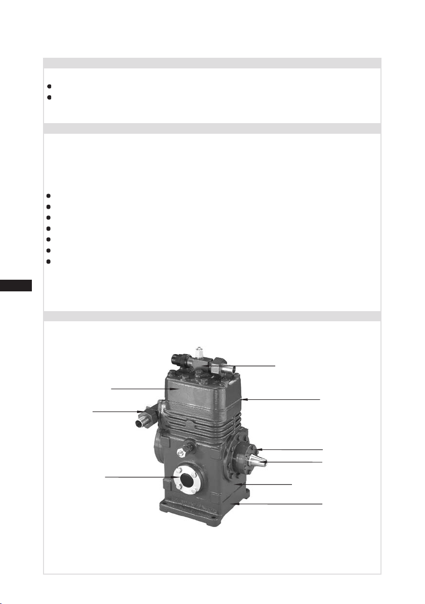
F2, F3
Cylinder cover
Suction
shut-off valve
3
F2
Discharge shut-off valve
Valve plate
Oil sightglass
Fig. 1
Dimension and connection values can be found in Chapter 10
6
Shaft seal
Shaft end
Compressor housing
Base plate
09702-09.2013-DGbF
D
GB
F
E
7
09702-09.2013-DGbF
2 | Product description
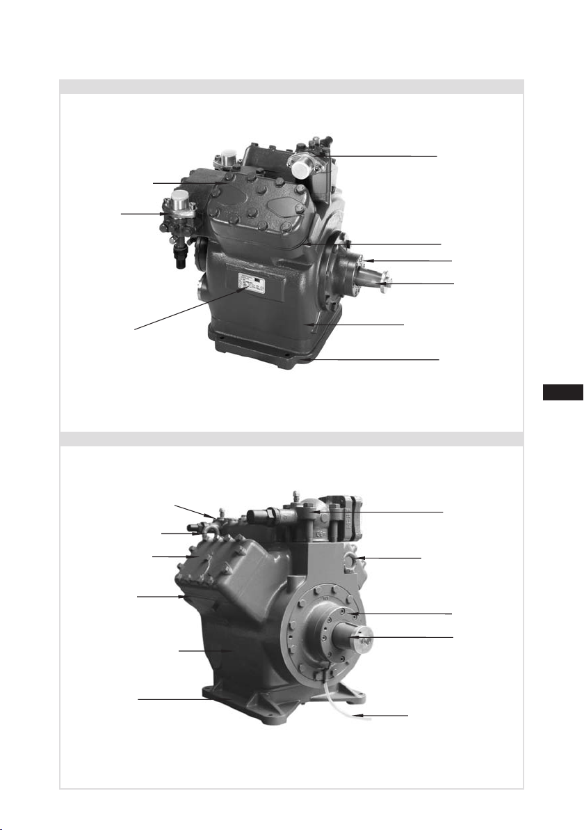
F4, F5
F5
Cylinder cover
Suction
shut-off valve
Name plate
Fig. 2
F14, F16
Discharge
shut-off valve
Valve plate
Shaft seal
Shaft end
Compressor housing
Base plate
Discharge shut-off valve
Transport eyelet
Cylinder cover
Valve plate
Compressor housing
Base plate
Dimension and connection values can be found in Chapter 10
F16
Suction
shut-off valve
Transport eyelet
Shaft seal
Shaft end
Leak oil drain hose
Fig. 3
D
GB
F
E
2 | Product description
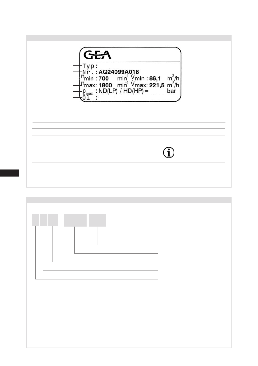
2.2 Name plate (example)
GEA Bock GmbH
72636 Frickenhausen, Germany
1
2
3
4
5
6
1 Type designation
2 Machine number
3 Rotation speed minimum with a corresponding displacement
4 Rotation speed maximum with a corresponding displacement
5 ND(LP): Max. admissible operating pressure Suction side
HD(HP): Max. admissible operating pressure
High-pressure side
6 Oil type charged at factory
2.3 Type code (example)
FX16/2 051
19/28
SE55
Fig. 4
Observe the limit of
application diagrams!
F 14
X
)
X - Ester oil charge (HFC refrigerant R134a, R404A/R507, R407C)
¹
)
²
Indication only at F14, F16
8
1166
/
NH
3
NH3 version
Swept volume
Size
)
Oil charge
Series
¹
)
²
09702-09.2013-DGbF
D
GB
F
E
9
09702-09.2013-DGbF
3 | Areas of application F, F-NH
3.1 Refrigerants
• HFKW: R134a, R404A/R507, R407C
• (H)FCKW: R22
NH3:
3.2 Oil charge
The compressors are lled with the following oil type at the factory:
- for R134a, R404A/R507, R407C FUCHS Reniso Triton SE 55
- for R22 FUCHS Reniso SP 46
Compressors with ester oil charge (FUCHS Reniso Triton SE 55) are marked with an X in the type
designation (e.g. FX16/2051).
R7 17
3
INFO!
Alternatives: see lubricants table, Chapter 7.6
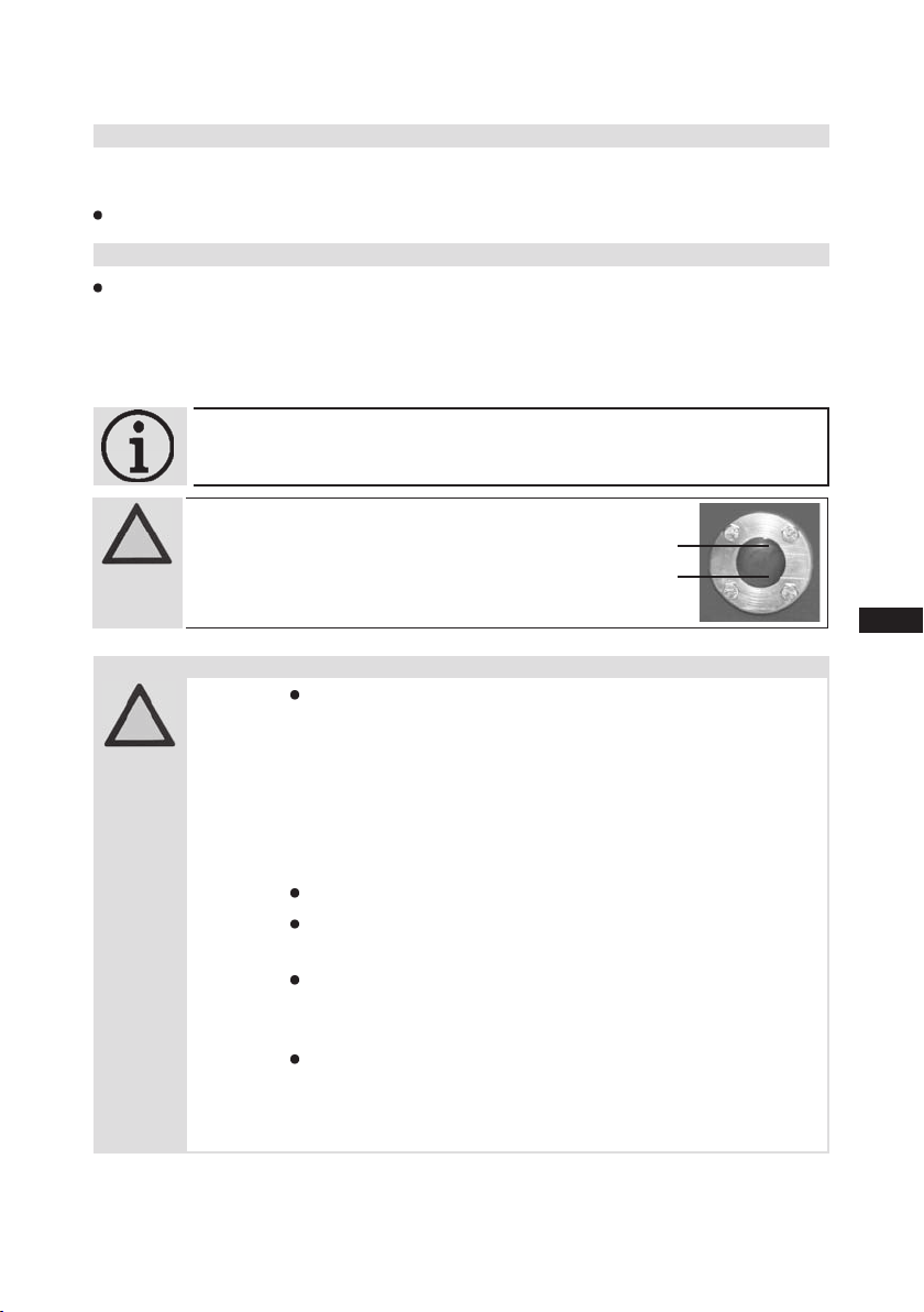
ATTENTION!
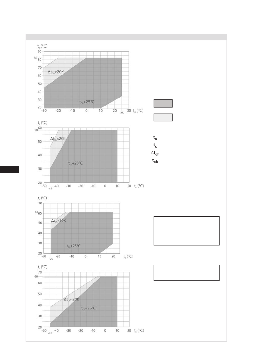
3.3 Operating limits
ATTENTION! Compressor operation is possible within the operating
limits shown in the diagrams. Please note the signicance
of the shaded areas. Thresholds should not be selected as design
or continuous operating points.
- Max. permissible discharge end temperature: 140°C
- Max. permissible switching frequency: 12x /h
- A minimum running time of 3 min. steady-state condition
Avoid continuous operation near the threshold.
For operation with supplementary cooling:
- Use only oils with high thermal stability.
For operation with capacity regulator:
- The suction gas superheat temperature may need to be reduced
When operating in the vacuum range, there is a danger of air
For refilling, we recommend the above oil types.
The oil level must be in the visible
part of the sight glass; damage
to the compressor is possible if
overfilled or underfilled!
(continuous operation) must be achieved.
or set individuallywhen operating near to the threshold.
entering on the suction side. This can cause chemical reactions, a
pressure rise in the condenser and an elevated compressed-gas
temperature. Prevent the ingress of air at all costs!
max. oil level
min. oil level
Fig. 5
D
GB
F
E
3| Areas of application F
3.3 Operating limits
R134a
Fig. 6
R404A/R507
Fig. 7
Unlimited
application range
Reduced suction gas
temperature
Evaporating temperature (°C)
Condensing temperature (°C)
Suction gas superheat (K)
Suction gas temperature (°C)
Permissible rotation speeds:
F2, F3: 960 - 1800 rpm
F4, F5: 500 - 1800 rpm
F14, F16: 700 - 1800 rpm
10
Fig. 8
Fig. 9
R407C
R22
Maximum admissible
operating pressure (g)
High pressure side (LP/HP)1):
19/28 bar
1)
LP = Low pressure
HP = High pressure
Design for other
areas on request
09702-09.2013-DGbF
D
GB
F
E
11
09702-09.2013-DGbF
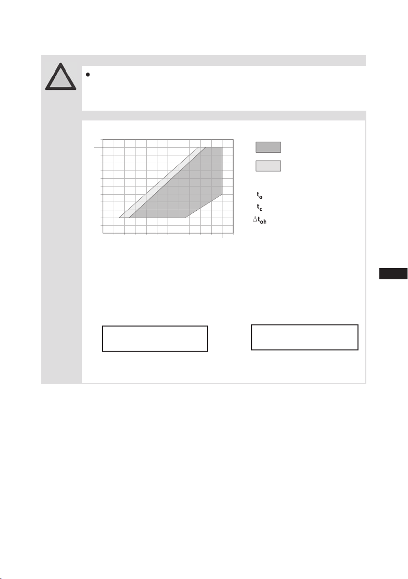
4| Areas of application F-NH
3
The compressors are lled with the following oil type at the factory:
- for R717: Fuchs Reniso KC 68
4.1 Oil charge NH
3
4.2 Operating limits NH
3
Fig. 10
NH
3
Permissible rotation speeds:
F2 NH
3
, F3 NH3: 960 - 1500 rpm
F4 NH
3
, F5 NH3: 500 - 1500 rpm
F14 NH
3
, F16 NH3: 700 - 1500 rpm
Supplementary cooling
necessary
(e.g. water-cooled
cylinder covers)
Unlimited
application range
Evaporating temperature (°C)
Condensing temperature (°C)
Suction gas superheat (K)
Design for other
areas on request
Max. permissible operating
pressure (LP/HP)1): 19/25 bar
1)
LP = Low pressure
HP = High pressure
15
Nh3
-30 -20 0-10 10
20
t (°C)
o
-40
0
10
60
t (°C)
c
40
30
20
50
55
?t
Oh
5K
NH
3
D
F
E
1
2
GB
F
E
5| Compressor assembly
INFO! New compressors are factory-lled with inert gas (3 bar nitrogen).
Leave this service charge in the compressor for as long as possible
and prevent the ingress of air.
Check the compressor for transport damage before starting any
work.
5.1 Setting up
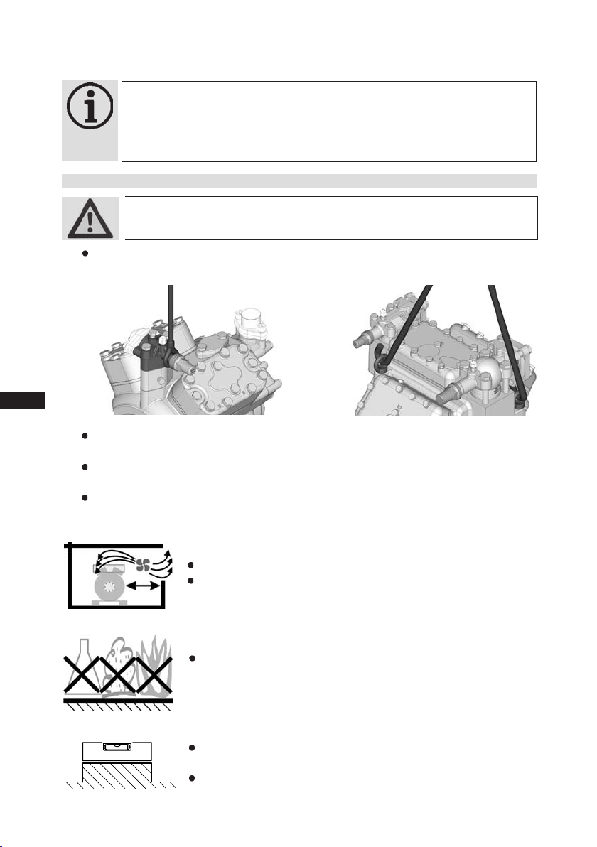
WARNING! Move compressors only with hoists that have adequate load-bearing
capacity.
Transport and suspension unit on the eyebolt (Fig. 12, F14 to F16) or direct on the discharge
line valve (Fig. 11, F2 to F5).
Fig. 11
Fittings (e.g. pipe holders, additional units etc.) on the compressor are permissible only
following consultation with Bock.
Setup on an even surface or frame with sufcient load-bearing capacity. Use all 4 fastening
points.
Correct setup of the compressor and mounting of the belt drive are decisive for running comfort,
operating safety and the service life of the compressor.
Fig. 12
12
Fig. 13
Fig. 14
Fig. 15
Provide adequate clearance for maintenance work.
Provide adequate ventilation for the drive motor.
Do not use in a dusty, damp atmosphere or a combustible
environment.
Set up on an even surface or frame with sufcient load-bearing
capacity.
Compressors and drive motors are basically rigid and should be
mounted together on a base frame.
09702-09.2013-DGbF
D
GB
F
E
13
09702-09.2013-DGbF
5| Compressor assembly
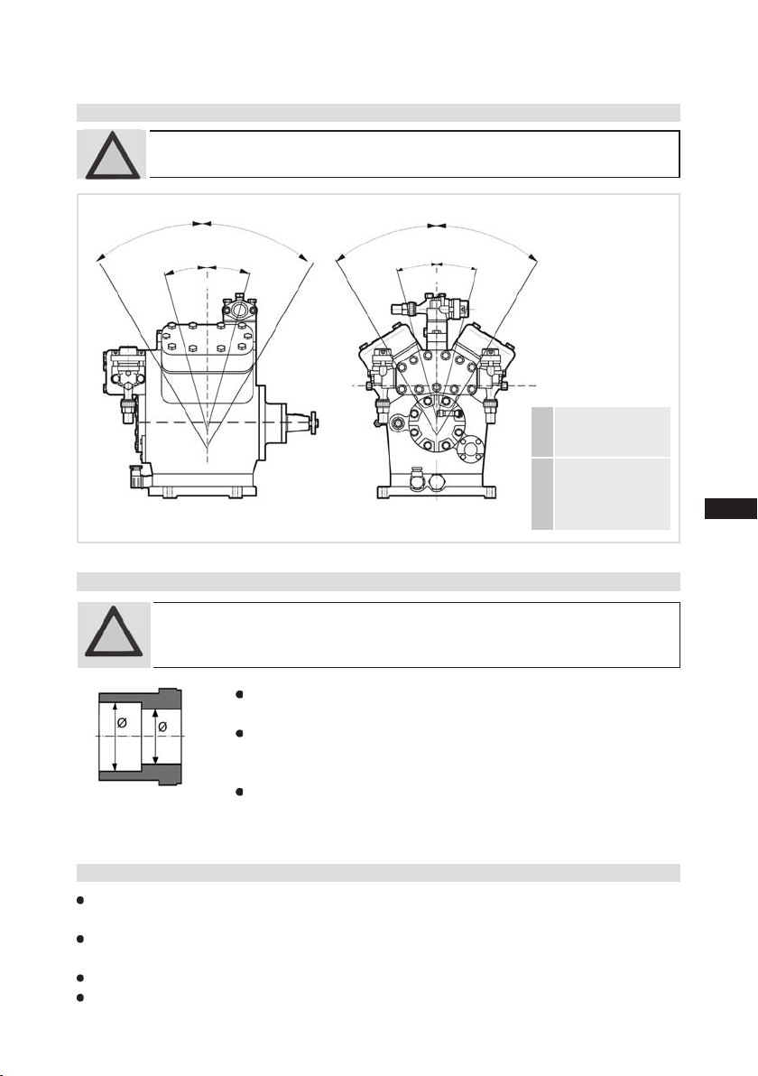
5.2 Maximum permissible inclination
ATTENTION! Poor lubrication can damage the compressor.
Respect the stated values.
A A
a
Fig. 16
5.3 Pipe connections
ATTENTION! Overheating can damage the valve.
Remove the pipe supports from the valve for soldering.
Only solder using inert gas to inhibit oxidation products (scale).
Fig. 17: Stepped
internal diameters
A A
a
a
The pipe connections have stepped internal diameters so that pipes with
standard millimetre and inch dimensions can be used.
The connection diameters of the shut-off valves are designed for maximum
compressor output. The required pipe cross-section must be matched
to the capacity. The same applies for non-return valves.
The required tightening torque for the ange connection is 60 Nm.
a
max. 30°,
A
max. 2 minutes
max. 15°,
a
continuous
operation
5.4 Pipes
Pipes and system components must be clean and dry inside and free of scale, swarf and layers of
rust and phosphate. Only use air-tight parts.
Lay pipes correctly. Suitable vibration compensators must be provided to prevent pipes being
cracked and broken by severe vibrations.
Ensure a proper oil return.
Keep pressure losses to an absolute minimum.
D
GB
F
E
5| Compressor assembly
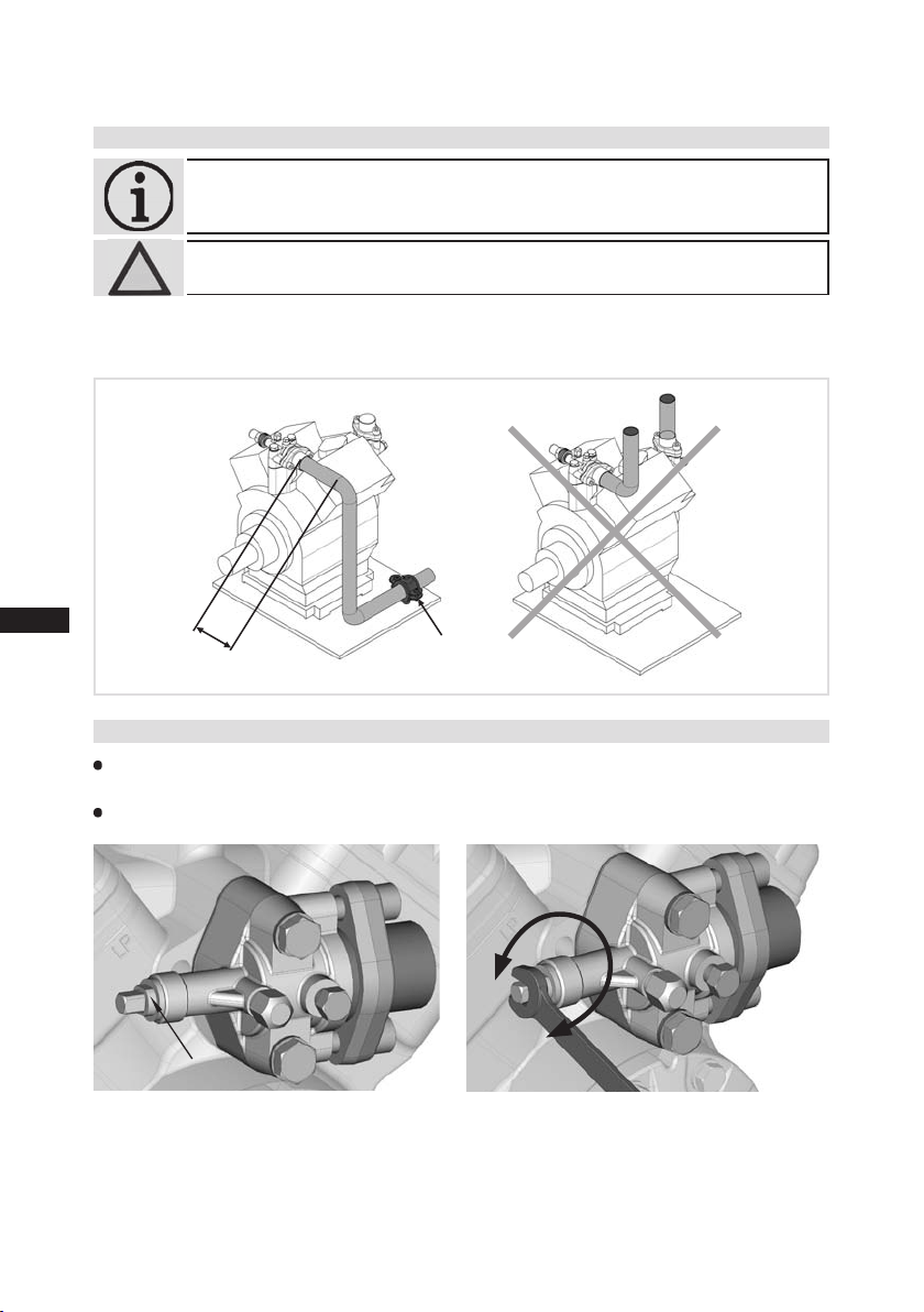
5.5 Laying suction and discharge lines
INFO! Proper layout of the suction and discharge lines directly after
the compressor is integral to the system’s smooth running and
vibration behaviour.
ATTENTION! Improperly installed pipes can cause cracks and tears, the result
being a loss of refrigerant.
A rule of thumb:
Always lay the rst pipe section starting from the shut-off valve downwards
and parallel to the drive shaft.
As shor t as
possible
Rigid
Fixed point
Fig. 18
5.6 Operating the shut-off valves
Before opening or closing the shut-off valve, release the valve spindle seal by approx. ¼ of a turn
counter-clockwise.
After activating the shut-off valve, re-tighten the adjustable valve spindle seal clockwise.
loosen
tighten
Valve spindle seal
Fig. 19 Fig. 20
14
09702-09.2013-DGbF

D
GB
F
E
15
09702-09.2013-DGbF
5| Compressor assembly
5.7 Operating mode of the lockable service connections
Service connection
closed
Spindle
Connection
blocked
Pipe connection
Opening the shut-off valve:
Spindle: turn to the left (counter-clockwise) as far as it will go.
—> The shut-off valve is then fully open and the service connection is closed.
The connection which is not lockable is provided for safety devices.
Service connection
opened
Spindle
Connection
open
Pipe connection
Opening the service connection
Spindle: ½ - 1 rotation to the right (clockwise).
—> The service connection is then open and the shut-off valve is also open.
The connection which is not lockable is provided for safety devices.
Fig. 21
Fig. 22

D
GB
F
E
5| Compressor assembly
5.8 Drive
ATTENTION! Faulty alignment results in premature failure of the coupling and
bearing damage!
CAUTION! Mount suitable safeguards when driving the compressor by means
of V-belts or shaft couplings!
The compressors of the F series can be driven by V-belts or directly by shaft couplings.
V-belt:
Proper assembly of belt drive:
- The pulleys of compressor and drive motor must be rmly mounted and in line.
- Only use V-belts with calibrated lengths.
- Select axis spacing, V-belt length and belt pre-tension according to the instructions issued by
the V-belt manufacturer. Avoid belt uttering.
- Check belt pre-tension after running-in time.
Direct drive with shaft coupling:
Direct drive with shaft couplings demands highly precise aligning of compressor shaft and
motor shaft.
Use the Bock shaft couplings „WK“ and observe the enclosed assembly instructions.
16
09702-09.2013-DGbF

D
GB
F
E
17
09702-09.2013-DGbF
5| Compressor assembly
5.9 Oil sump heating
When the compressor is at a standstill, refrigerant diffuses into the lubrication oil of the compressor
housing, depending on pressure and ambient temperature. This reduces the lubrication capacity of
the oil. When the compressor starts up, the refrigerant contained in the oil evaporates out through
the reduction in pressure. The consepuences can be lack of lubrication, foaming and migration of the
oil, which can eventually lead to compressor damage.
To prevent this, the oil can be heated via an oil sump heater.
Operation:
Connection: Oil sump heater must be connected via an auxiliary contact (or parallel wired
Oil sump heater: 230 V – 1 – 50/60Hz, IP65
Type
Electrical power
(Watt)
NH
Oil sump heater ON at standstill of the compressor.
Oil sump heater OFF during operation of the compressor
auxiliary contact) of the motor contactor to a separate electric circuit.
F2 F3 F4 F5 F14 F16
40 60 80 80 140 140
INFO! Same electrical performance even on NH3 compressors
3
WARNING! The oil sump heater must not be connected to the electrical circuit
of the safety control chain !

D
GB
F
E
6| Commissioning
6.1 Preparations for start-up
INFO! To protect the compressor against inadmissible operating conditions,
high pressure and low pressure pressostats are mandatory on the
installation side.
The compressor has undergone trials in the factory and all functions have been tested. There are
therefore no special running-in instructions.
Check the compressor for transport damage!
6.2 Pressure strength test
DANGER! Bursting! The compressor must only be pressurised using nitrogen
(N2). Never pressurise with oxygen or other gases!
The maximum permissible overpressure of the compressor must not
be exceeded at any time during the testing process (see name plate
data)! Do not mix any refrigerant with the nitrogen as this could
cause the ignition limit to shift into the critical range.
The compressor has been factory-tested for pressure resistance. The following must be observed if
the entire plant is subjected to an additional pressure strength test:
Test the refrigeration circuit according to EN 378-2 or a corresponding safety standard.
6.3 Leak test
DANGER! Bursting!
Do not mix any refrigerant with the nitrogen (N2) as this could cause
the ignition limit to shift into the critical range.
Carry out the leak test of the refrigerating system in accordance with EN 378-2 or a corresponding
safety standard without including the compressor.
6.4 Evacuation
First evacuate the system and then include the compressor in the evacuation process.
Relieve the compressor pressure.
Open the suction and discharge line valves.
Evacuate the suction and discharge pressure sides using the vacuum pump.
At the end of the evacuation process, the vacuum should be < 1.5 mbar when the pump is switched off.
Repeat the process as often as is required.
18
09702-09.2013-DGbF

D
GB
F
E
19
09702-09.2013-DGbF
6| Commissioning
6.5 Refrigerant charge
CAUTION! Wear personal protective clothing such as goggles and
protective gloves!
Make sure that the suction and discharge line valves are open.
With the compressor switched off, add the liquid refrigerant directly to the condenser or receiver,
breaking the vacuum.
If the refrigerant needs topping up after starting the compressor, it can be topped up in vapour
form on the suction side, or, taking suitable precautions, also in liquid form at the inlet to the
evaporator.
ATTENTION!
the compressor.
It is not permissible to mix additives with the oil and refrigerant.
6.6 Shaft seal
ATTENTION! Failure to observe the following instructions can cause loss of
INFO! The shaft seal seals and lubricates with oil. An oil leakage of
The compressor shaft is sealed to outside using a shaft seal. The sealing element rotates with the
shaft.
The following is especially important to ensuring fault-free operation:
The complete refrigerant circuit must be correctly executed and clean inside.
Heavy shocks and vibrations to the shaft as well as continuous cyclic operation are to be avoided.
The sealing surfaces can stick together during prolonged downtimes (e.g. winter). Therefore, run
the system every 4 weeks for 10 minutes.
Avoid overlling the system with refrigerant!
To avoid shifts in concentration, zeotropic refrigerant blends
must always only be lled into the refrigerating plant in liquid
form.
Do not pour liquid coolant through the suction line valve on
refrigerant and damage to the shaft seal!
0.05 ml per operating hour is therefore normal. This applies
particularly during the run-in phase (200 - 300 h).
The compressor types F14 and F16 are equipped with a leak oil
drain hose (see chapter 10 and 11). The leak oil is continually
discharged through the leak oil drain hose. To collect the leak oil,
a receptacle is to be provided by the plant operator. Dispose of
the leak oil in accordance with the valid national regulations.

D
GB
F
E
6| Commissioning
6.7 Shaft seal change
As changing the shaft seal involves opening the refrigerant circuit, this is recommended only if the
seal is losing refrigerant. Replacing the shaft seal is described in the spare part kit concerned.
6.8 Start-up
WARNING! Ensure that both shut-off valves are open before starting
the compressor!
Check that the safety and protection devices (pressure switch, motor protection, electrical
contact protection measures, etc.) are all functioning properly.
Switch on the compressor and allow to run for a minimum of 10 min.
Check the oil level by: The oil must be visible in the sightglass.
ATTENTION! If larger quantities of oil have to be topped up, there is a risk of oil
hammer effects. If this is the case check the oil return!
6.9 Avoiding slugging
ATTENTION! Slugging can damage the compressor and cause
coolant to leak.
To prevent slugging:
The complete refrigeration system must be properly designed.
All components must be compatibly rated with each other with regard to output
(particularly the evaporator and expansion valves).
Suction gas superheat at the compressor input should be min. 7 - 10 K. (check the setting
of the expansion valve).
The system must reach a state of equilibrium.
Particularly in critical systems (e.g. several evaporator points), measures are recommended such
as replacement of liquid traps, solenoid valve in the liquid line, etc.
There should be no movement of coolant whatsoever while the compressor is at
a standstill.
20
09702-09.2013-DGbF

D
GB
F
E
21
09702-09.2013-DGbF
7| Maintenance
7.1 Preparation
WARNING! Before starting any work on the compressor:
Switch off the compressor and secure it to prevent a restart.
Relieve compressor of system pressure.
Prevent air from inltrating the system!
After maintenance has been performed:
Connect safety switch.
Evacuate compressor.
Release switch lock.
7.2 Work to be carried out
To guarantee optimum operating safety and service life of the compressor, we recommend performing service and checking work at regular intervals of time:
Oil change:
- In series plants produced in the factory not mandatory.
- In field installations or operating in the application limit range, first oil change after approx.
100 - 200 operating hours, then approx. every 3 years or 10,000 - 12,000 operating hours.
- for NH3 plants: oil change every year or every 5.000 operating hours.
Dispose of old oil according to the regulations, observe national regulations.
Annual checks: Oil level, tightness, running noise, pressures, temperatures, function of auxiliary
devices such as a oil sump heater, pressure switch. Comply with the national regulations!
7.3 Spare parts recommendation
Type
Designation
Set gaskets 08069 08070 08071 08072 08492 08493
Shaft seal 08001 08001 08008 08008 08444 08012
Valve plate set 08 314 0 8198 08198 08436 08498 08498
Oil pump 08043 08043 08044 08044 08795 08795
Oil sump heater 08423 08424 08425 08425 08426 08426
Only use original Bock spare parts!
F2 F3 F4 F5
Ref. No.
F14/ 1166
F14 /136 6
F16 /1751
F16/2051

7| Maintenance
D
GB
F
E
7.4 Spare parts recommendation NH
NH
3
Designation
Set gaskets 08069 08070 08071 08072 08492 08493
Shaft seal 08001 08001 08008 08008 08444 0 8012
Valve plate set NH
Oil pump 08043 08043 08044 08044 08799 08799
Oil sump heater 08423 08424 08425 08425 08426 08426
Type
3
3
F2 NH3F3 NH3F4 NH3F5 NH
08841 08842 08842 08843 08844 08844
3
Ref. No.
F14/ 1166 NH
F14 /136 6 NH
F16 /1751 NH
3
F16/2051 NH
3
Only use original Bock spare parts!
7.5 Accessories
Accessories available can be found in the F-Catalogue (Bock Ref.-No. 96023) or
on the Internet at www.bock.de.
7.6 Excerpt from the lubricant table
The oil grade lled as standard in the factory is noted on the name plate. This oil grade should be
used preferably. Alternatives to this are listed in the following excerpt from our lubricant table.
Refrigerant Bock series oil grades
HFKW
(e.g.
R134a,
Fuchs Reniso Triton SE 55
R404A/R507, R407C)
HFCKW
(e.g.
R22)
Fuchs Reniso SP 46
Recommended alternatives
FUCHS Reniso Triton SEZ 32
ICI Emkarate RL 32 H, S
MOBIL Arctic EAL 32
SHELL Clavus R 32
FUCHS Reniso, z.B. KM, HP, SP 32
SHELL Clavus SD 22-12
TEX ACO Capella WF 46
Fuchs Reniso KC 68
-
for ooded operation
NH
3
Fuchs Reniso Synth 68
for applications using a plate
heat exchanger
Information on further suitable oils on request.
3
3
7.7 Decommissioning
Close the shut-off valves on the compressor. Drain the refrigerant (it must not be discharged into the
environment) and dispose of it according to the regulations. When the compressor is depressurised,
undo the fastening screws of the shut-off valves. Remove the compressor using an appropriate hoist.
Dispose of the oil inside in accordance with the applicable national regulations.
22
09702-09.2013-DGbF

D
GB
F
E
23
09702-09.2013-DGbF
8| Technical data F2 - F16
Oil charge Rotation speed
)
¹
Connections
)
Weight ²
range
line SV
Suction
line DV
Discharge
rpm
ltr.
inch
I
mm
inch
I
mm
2,6
/
3
1
I
35
500-1800
5,0 700-1800
3,8 700-1800
3,8
8
/
8
8
3
1
1
I
2 x 35
/
2
I
54
/
1
2
I
54
8
960 -180 0
1,5
0,8
8
/
8
/
1
5
1
I
I
16
28
8
8
8
/
8
/
5
I
16
18
/
8
1
/
7
1
I
I
22
28
28
51
3
1
I
35
85
5
/
1
I
42
149
/
5
1
I
42
175
8
(1450/1740 rpm)
Displacement
No. of
cylinders
Type
/h kg
3
m
10,50 / 12,60
F2
20,30 / 24,30
2
F3
40,50 / 48,60
F4
73,70 / 88,40
101,40 / 121,70
F5
4
F14/1166
4
178,40 / 214,10
119,00 / 142,80
152,20 / 182,60
6
in standard design
F16 /1751
F14 /136 6
for soldering joint
F16/2051
)
)
¹
²

9| Technical data F2-NH3 - F16-NH
3
D
GB
F
E
Oil charge Rotation speed
)
¹
Connections
)
Weight ²
range
line SV
Suction
line DV
Discharge
rpm
0,8
18 18
18
2,6
30 38
51
500-1500
3,8
38 2 x 38
85
6,3 700-1500
49 60
158
7, 5 700-1500
49 60
183
960-1500
1,5
25 30
28
24
3
(1450 rpm)
Displacement
No. of
cylinders
Type
/h kg mm mm ltr.
m
10,5 0
20,30
2
3
3
NH
F3
F2 NH
40,50
NH
F4
73,70
4
3
NH
F5
118,9 0
101,50
4
3
NH
3
F14/1166
178,40
152,20
6
3
3
3
NH
in standard design
F16 /1751
F14 /136 6 NH
for soldering joint
F16/2051 NH
)
)
¹
²
09702-09.2013-DGbF

D
GB
F
E
25
09702-09.2013-DGbF
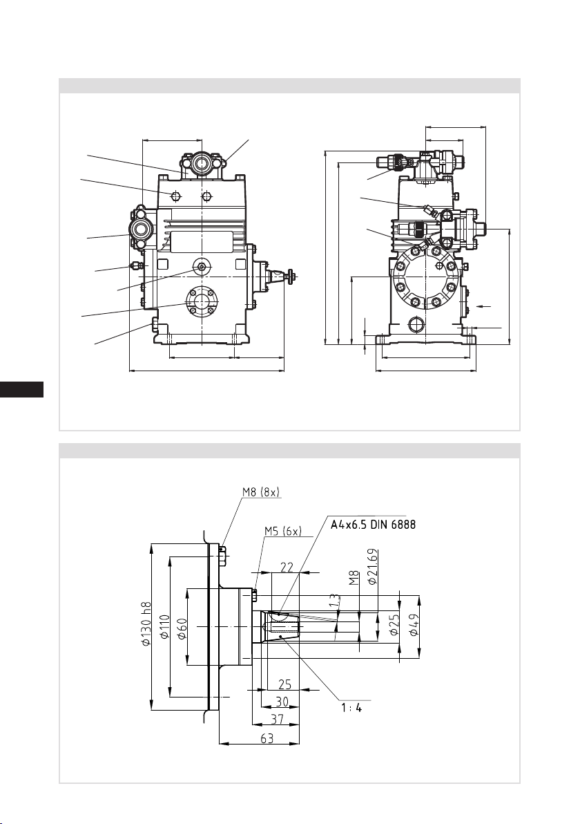
10| Dimensions and connections F
101
114 77
ca.255
123
195
310
ca.340
134
152
4xØ9
15
B1
B/L
B
DV
A1
SV
A
H/D1
K
F/G
X
Compressor type F2
Shaft end F2
Fig. 23
Dimensions in mm
Woodruff key
Cone
Dimensions in mm
Dimensions for view X see page 32
Fig. 24

D
118
130
96.5
ca.315
90
135
175
200
4xØ9
230
17
135
360
ca.400
DV
B/L
A
A1
SV
C/E
D/D1/H
K
F/G
B1
X
GB
F
E
10| Dimensions and connections F
Compressor type F3
Fig. 25
Dimensions in mm
Shaft end F3
26
Woodruff key
Cone
Dimensions in mm
Dimensions for view X see page 32
Fig. 26
09702-09.2013-DGbF

D
GB
F
E
27
09702-09.2013-DGbF
10| Dimensions and connections F
4x 11
ca.305
170
ca.455
130
ca.225
K
F
J
H
D
B DVB1L
SV
A
A1
C/E
D1
395
210
240
25
ca.430
X
Compressor type F4
Shaft end F4
Fig. 27
Dimensions in mm
Woodruff key
Dimensions for view X see page 32
Cone
Dimensions in mm
Fig. 28

D
4xØ11
150
169
ca.470
ca.465
D
D1
H
25
170
340
430
240
270
246
ca.355
B1
L
B
DV
SV
A
A1
C/E
K
F
J
X
GB
F
E
10| Dimensions and connections F
Compressor type F5
Fig. 29
Dimensions in mm
Shaft end F5
Woodruff key
28
Cone
Dimensions for view X see page 32
Dimensions in mm
Fig. 30
09702-09.2013-DGbF

D
GB
F
E
29
09702-09.2013-DGbF
10| Dimensions and connections F
362
124
4xØ13.5
290
320
ca.510 (560)
448 (498)
432 (482)
180 (230)
20
ca.415
121.5290
342
ca.530
X Y Y
SV
DV
L
A
B2
D
B
H
D1
A1
P
B1
B
C
E
K
F
J
ÖV1
Compressor type F14 F14/1166 F14/1366
Dimensions in mm
Dimensions in () = with elevated base plate
Shaft end F14
Fig. 31
Woodruff key
Cone
Dimensions for view X, Y see page 32
Leak oil
drain hose
Fig. 32
Dimensions in mm

D
290
143.5290
B
A1
B1
B
C
K
F
J
ÖV1
P
D1
H
E
Y
Y
(520)
20
320
452 (502)
200 (250)
470
ca.515
ca.535 (585)
4x 13.5
A
SV
DV
L
B2
D
X
363
342
ca.580
170
GB
F
E
10| Dimensions and connections F
Compressor type F16 F16/1751 F16/2051
Fig. 33
Dimensions in mm
Dimensions in () = with elevated base plate
Shaft end F16
Woodruff key
Leak oil
30
drain hose
Cone
Dimensions for view X, Y see page 32
Dimensions in mm
Fig. 34
09702-09.2013-DGbF

D
GB
F
E
31
09702-09.2013-DGbF
10| Dimensions and connections F
" UNF
" UNF
" UNF
NPT F
"
8
/
/
1
7
" UNF
NPT F
"
8
/
/
1
7
" UNF
NPT F
"
8
/
/
1
7
" UNF
NPT F
"
8
/
/
1
7
" UNF
NPT F
"
8
/
see technical data, Chapter 8
/
1
7
" UNF
NPT F
"
8
16
/
1
NPT F
"
8
16
/
1
" NPT F
8
16
/
1
" NPT F
8
16
/
1
" NPT F
8
16
/
1
16
16
/
/
7
7
" UNF
" UNF
16
16
/
/
7
7
" UNF
16
/
7
" UNF
16
/
7
" UNF
16
/
7
" UNF
16
16
/
/
7
7
" UNF
" UNF
16
16
/
/
7
7
" UNF
" UNF
16
16
/
/
7
7
" UNF
" UNF
16
16
/
/
7
7
NPT F
NPT F
"
"
8
8
/
/
1
1
" UNF
" UNF
8
16
/
/
5
7
" UNF
" UNF
8
16
/
/
5
7
" UNF
" NPT F
8
16
/
/
7
1
" UNF
" NPT F
8
16
/
/
7
1
NPT F
"
" NPT F
8
8
/
/
1
M22 x 1,5 M22 x 1,5 M22 x 1,5 M26 x 1,5 M26 x 1,5
1
M22 x 1,5
M22 x 1,5
M22 x 1,5
M22 x 1,5 M22 x 1,5 M22 x 1,5 M22 x 1,5
M22 x 1,5
1)
" NPT F
8
/
1
M22 x 1,5
3)
" NPT F
8
/
1
4 hole M6
3)
" NPT F
8
/
1
" NPT F
8
/
1
" NPT F
8
/
1
" UNF
16
/
7
" UNF
16
/
M20 x 1,5 M20 x 1,5
7
)
" NPT F
8
/
1
"
8
/
3
Suction line
Discharge line
Connections F2 F3 F4 F5 F14 F16
SV
DV
" UNF
" UNF
16
16
/
/
7
7
Connection suction side, not lockable
Connection suction side, lockable
A
A1
" UNF
" NPT F
8
16
/
/
7
1
Connection discharge side, not lockable
Connection discharge side, lockable
B
B1
Connection discharge side, not lockable - - - -
B2
-
OIL
Connection oil pressure safety switch
C
-
LP
Connection oil pressure safety switch
D
1)
"
8
/
8
Connection oil return from oil separator
D1
3
R
Connection oil pressure gauge -
Oil drain plug
E
F
" NPT F
/
1
"
8
/
" NPT F
3
8
/
R
1
Oil charge plug
Oil sump heater
H
J
" NPT F
8
/
4 hole M6 4 hole M6 4 hole M6 4 hole M6 4 hole M6
1
Sight glass
Connection thermal protection thermostat
K
L
- - - -
- - - -
for differential oil pressure sensor
Connection
Oil service valve
P
ÖV
Oil sump heating optional
No connection available as standard. Available on request (Connection R
Second sight glass can be attached, Positioning view Y (optional, available only as original equipment)
1)
2)
3)

D
50
4
5
°
90°
GB
F
E
10| Dimensions and connections
10.1 View X, Y
• Oil sight glass
• Connection facility for parallel operation
Position view X:
F2, F3, F4, F5, F14, F16
4 hole oil sight glass
Connection facilities
Position view Y:
F14, F16
Second oil sight glass can be attached as an
option (available as original equipment only)
mm
4 x M6, 10 mm deep
Operation with oil level regulator
Art.Nr. 80462
BOCK adapter for oil level regulator,
ts the makes ESK, AC+R, CARLY.
3 hole fastener on the side of the oil level
regulator
4 hole fastener on the side of the
compressor
32
Operation with common
oil-gas balance pipe
example: 3 compressors in parallel
Art.Nr. 80463
BOCK adapter for oil-gas regulator,
single design,
4 hole steel connector for Pipe Ø 35 mm,
ts all sight glass positions.
1 item per compressor required.
Fig. 35
09702-09.2013-DGbF

D
GB
F
E
33
09702-09.2013-DGbF
11| Dimensions and connections F-NH
4xØ9
134
152
15
123
ca.330
10595
114 77
ca.265
300
195
B1
B/L
DV
SV
A1
H/D1
K
F/G
X
4xØ9
134
152
15
123
ca.330
10595
B1
B/L
DV
SV
A1
H/D1
K
F/G
X
3
Compressor type F2 NH
Shaft end F2 NH
3
3
Fig. 36
Dimensions in mm
Woodruff key
Cone
Dimensions in mm
Dimensions for view X see page 40
Fig. 37
11| Dimensions and connections F-NH
130
96.5
ca.345
175
200
4xØ9
118
120
75
230
17
135
ca.365
ca.390
B
L
SV
C/E
D/D1/H
K
F/G
DV
B1
A
A1
X
3
D
GB
F
E
Compressor type F3 NH
Shaft end F3 NH
3
3
Fig. 38
Dimensions in mm
34
Woodruff key
Cone
Dimensions in mm
Dimensions for view X see page 40
Fig. 39
09702-09.2013-DGbF

D
GB
F
E
35
09702-09.2013-DGbF
11| Dimensions and connections F-NH
11(4x)
ca.305
V= Schneidringverschraubung
S= Schweißanschluß S= Welded connection S= Raccordement soudé
V= Connection à vis taraudeusseV= Cutting rind connection
Anschlüsse Connections Raccords
SV Sauga bsperrventil, Rohr
Suction line valve, tube Vanne d' arrêt d' aspiration, de tuyau mm 38x32 S
DV Druckabsp errventil, Rohr
Discharge line valve, tube Vanne d' arrêt de refoulement, de tuyau mm 30x24 S
A Ansch luß Saugseite, nicht absperrbar Connection sucti on side, not lockable Raccord côté aspiration, non obturable mm
6 V
A1 Anschluß Saugseite, absperrbar Connect ion suction side, lockable Raccord côté aspirati on, obturable mm 6 V
B Ansch luß Druckseite, nicht absperrbar Connection discharge side, not lockable Raccord côté refoulement, non obturable mm
6 V
B1 Anschluß Druckseite, absperrbar Connection discharge side, lockable Raccord côté refoulement, obturable mm
6 V
C Anschluß Ö ldrucksicherheitsschalter OIL Connection oil pressure safety switch OIL Raccord pressostat de sécurité d' huile OIL mm 6 V
D Anschluß Ö ldrucksicherheitsschalter LP Connection oil pressure safety switch LP Raccord pressostat de sécurité d'huile LP mm
6 V
D1 Anschluß Ölrückführung vom Ölabscheider Connection oil return from oil separator Raccord retour d'huile de séparateur d'huile mm
10 V
E Ansch luß Öldruckmanometer Co nnection oil pressure gauge Raccord du manomètre d e pression d'huile mm 6 V
F Stopfen Ölablaß Oil drain plug Bouchon de vidange d'huile mm M22x1,5
G Stopfen Ölsumpfheizung Oil sump heater plug Bouchon chauffage de carter d’huile mm M22x1,5
H Stopfen Ölfüllung O il charge plug Bouchon de remplissag e d'huile mm M22x1,5
K Schau glas Sight glass Voyant mm -
L Anschluß Wärmeschutzthermostat Connection thermal protection thermostat Raccord de thermostat de pro tection thermique Zoll 1/8 NPTF
2
34
5
6
78
B
X
213
130 169
ca.450
H
DV
B1L
SV
A
A1
C/E
K
F
G
D1
D
240
210
170
ca.425
25
398
11(4x)
ca.305
V= Connection à vis taraudeusseV= Cutting rind connection
Suction line valve, tube Vanne d' arrêt d' aspiration, de tuyau mm 38x32 S
Discharge line valve, tube Vanne d' arrêt de refoulement, de tuyau mm 30x24 S
6 V
6 V
6 V
6 V
10 V
F
E
D
C
1
2
34
H
DVB1L
SV
A
A1
C/E
K
F
G
D1
D
240
210
170
ca.425
25
398
3
Compressor type F4 NH
Shaft end F4 NH
3
3
Fig. 40
Dimensions in mm
Woodruff key
Cone
Dimensions for view X see page 40
Fig. 41
Dimensions in mm

11| Dimensions and connections F-NH
4xØ11
150
169
ca.470
ca.485
B
240
270
ca.355
B1
DV
246
L
A1
H
D1
D
25
170
347
464
SV
C/E
K
F
G
A
X
240
270
ca.355
B1
DV
246
L
H
D1
D
25
170
347
464
SV
C/E
K
F
G
3
D
GB
F
E
Compressor type F5 NH
Shaft end F5 NH
3
3
Fig. 42
Dimensions in mm
Woodruff key
36
Cone
Dimensions for view X see page 40
Fig. 43
Dimensions in mm
09702-09.2013-DGbF

D
GB
F
E
37
09702-09.2013-DGbF
11| Dimensions and connections F-NH
290
121.5
342
ca.530
DV
L
A
B2
D
SV
4xØ13.5
290
320
A1
B1
B
E
C
K
G
F
ÖV1
B
H
D1
362
124
ca.415
230
482
498
ca.560
20
X YY
4xØ13.5
290
320
A1
B1
B
E
C
K
G
F
ÖV1
B
H
D1
ca.415
230
482
498
ca.560
20
3
Compressor type F14 NH
Shaft end F14 NH
3
3
F14/1166 NH
3
F14/1366 NH
Dimensions in mm
3
Fig. 44
Leak oil
drain hose
Woodruff key
Cone
Dimensions in mm
Dimensions for view X, Y see page 40
Fig. 45

11| Dimensions and connections F-NH
290
F
E
D
C
1
2
34
B1
C
D1
B
G
F
B
B2
K
H
ÖV1
E
A1
D
ca.
502
320
515
250
520
20
4x 13,5
ca.585
Y
V= Connection à vis taraudeusse
S= Raccordement soudé
Y
mmVanne de vidange d'huile 6 V
6 V
6 V
6 V
10 V
290 143,5
290
A
SV
DV
L
X
342
363 170
ca.580
2
34
5
6
B1
C
D1
B
G
F
B
B2
K
H
ÖV1
E
A1
D
ca.
502
320
515
250
520
20
4x 13,5
ca.585
Y
V= Schneidringverschraubung
S= Schweißanschluß
V= Cutting rind connection
S= Welded connection
V= Connection à vis taraudeusse
Oil service valveÖlserviceventil
S= Raccordement soudé
Y
mmVanne de vidange d'huile 6 V
Anschlüsse Connections Raccords
SV Saugabsperrventil, Rohr Suction line valve, tube Vanne d'arrêt d'aspiration, de tuyau mm 60x54 S
DV Druckabsperrventil, Rohr Discharge line valve, tube Vanne d'arrêt de refoulement, de tuyau mm 49x42 S
A Anschluß Saugseite, nicht absperrbar Connection suction side, not lockable Raccord côté aspiration, non obturable Zoll 1/8" NPTF
A1 Anschluß Saugseite, absperrbar Connection suction side, lockable Raccord côté aspiration, obturable mm
6 V
B Anschluß Druckseite, nicht absperrbar Connection discharge side, not lockable Raccord côté refoulement, non obturable Zoll 1/8'' NPTF
B1 Anschluß Druckseite, absperrbar Connection discharge side, lockable Raccord côté refoulement, obturable mm
6 V
B2 Anschluß Druckseite, nicht absperrbar Connection discharge side, not lockable Raccord côté refoulement, non obturable mm 6 V
C Anschluß Öldrucksicherheitsschalter OIL Connection oil pressure safety switch OIL Raccord pressostat de sécurité d'huile OIL mm
6 V
D Anschluß Öldrucksicherheitsschalter LP Connection oil pressure safety switch LP Raccord pressostat de sécurité d'huile LP mm 6 V
D1 Anschluß Ölrückführung vom Ölscheider Connection oil return from oil separator Raccord retour d'huile de séparateur d'huile mm
10 V
E Anschluß Öldruckmanometer Connection oil pressure gauge Raccord du manomètre de pression d'huile mm 6 V
F Stopfen Ölablaß Oil drain plug Bouchon de vidange d'huile mm M26x1,5
G Stopfen Ölsumpfheizung Oil sump heater plug Bouchon chauffage du carter d'huile mm M22x1,5
H Stopfen Ölfüllung Oil charge plug Bouchon de remplissage d'huile mm M22x1,5
K Schauglas Sight glass Voyant mm -
L Anschluß Wärmeschutzthermostat Connection thermal protection thermostat Raccord de thermostat de protection thermique Zoll 1/8" NPTF
ÖV 1
3
D
GB
F
E
Compressor type F16 NH
Shaft end F16 NH
Leak oil
drain hose
38
3
3
F16/1751 NH
3
Woodruff key
Cone
Dimensions for view X see page 40
F16/2051 NH
Dimensions in mm
Dimensions in mm
3
Fig. 46
Fig. 47
09702-09.2013-DGbF

D
GB
F
E
39
09702-09.2013-DGbF
11| Dimensions and connections F-NH
3
3
1)
F16 NH
3
1)
F14 NH
3
F5 NH
3
1)
3
1)
F4 NH
1/8 " NPT F
1/8 " NPT F
Ø 6 V
Ø 6 V
1)
1)
1)
1)
Ø 6 V
Ø 6 V
Ø 6 V
Ø 6 V
1)
1)
1)
1)
1/8 " NPT F
1/8 " NPT F
Ø 6 V
Ø 6 V
1)
1)
1)
1)
Ø 6 V
Ø 6 V
Ø 6 V
Ø 6 V
1)
1)
Ø 6 V
Ø 6 V
1)
1)
1)
1)
Ø 6 V
Ø 6 V
Ø 6 V
Ø 6 V
1)
1)
1)
1)
Ø 6 V
Ø 6 V
Ø 6 V
Ø 6 V
1)
1)
Ø 6 V
Ø 10 V
1)
1)
Ø 6 V
Ø 10 V
1)
1)
Ø 6 V
Ø 10 V
1)
1)
Ø 6 V
Ø 10 V
2)
2)
M22 x 1,5 M22 x 1,5 M22 x 1,5 M22 x 1,5
1)
" NPT F
8
Ø 6 V
/
1
4 hole M6
1)
" NPT F
8
Ø 6 V
/
1
" NPT F
8
/
1
" NPT F
8
/
1
3
F3 NH
3
1)
1)
1)
Ø 6 V
Ø 6 V
1
Ø 6 V
" NPT F
8
/
1)
1)
Ø 6 V
Ø 6 V
Ø 6 V
see technical data, Chapter 8, F-NH
1)
1)
Ø 6 V
-
1)
Ø 10 V
-
1)
1)
Ø 6 V
Ø 10 V
1)
Ø 10 V
3
1)
" NPT F
8
M22 x 1,5 M22 x 1,5 M22 x 1,5 M26 x 1,5 M26 x 1,5
"
8
/
R
Ø 10 V
M22 x 1,5 M22 x 1,5 M22 x 1,5 M22 x 1,5 M22 x 1,5
1)
"
8
/
3
R
Ø 10 V
/
1
- - - -
" NPT F
8
/
4 hole M6 4 hole M6 4 hole M6 4 hole M6 4 hole M6
1
Suction line
Discharge line
Connections F2 NH
SV
DV
Connection suction side, not lockable -
A
Connection suction side, lockable
Connection discharge side, not lockable
A1
B
Connection discharge side, lockable
Connection discharge side, not lockable - - - -
B1
B2
OIL
Connection oil pressure safety switch
C
LP
Connection oil pressure safety switch
D
Connection oil return from oil separator
D1
Connection oil pressure gauge -
Oil drain plug
E
F
Oil sump heater plug
Oil charge plug
G
H
Sight glass
Connection thermal protection thermostat
K
L
Oil service valve
Second sightglass can be attached, positioning view Y (optional, only as original equipment)
ÖV
1) Compression joint for steel pipes
2)

D
50
4
5
°
90°
GB
F
E
11| Dimensions and connections F-NH
11.1 View X, Y
• Oil sight glass
• Connection facility for parallel operation
Position view X:
, F3 NH3, F4 NH3, F5 NH
F2 NH
3
, F16 NH
F14 NH
3
3
4 hole oil sight glass
3,
Position view Y:
F14 NH
, F16 NH
3
3
Second oil sight glass can be attached as an
option (available as original equipment only)
4 x M6, 10 mm deep
mm
3
Fig. 48
09702-09.2013-DGbF
40

D
GB
F
E
41
09702-09.2013-DGbF
12| Declaration of installation
DECLARATION OF INSTALLATION
for using the compressors within the European Union
(in accordance with Machinery Directive 2006/42/EC)
The manufacturer: GEA Bock GmbH, Benzstraße 7
D-72636 Frickenhausen, Tel.: 07022/9454-0
hereby declares that the refrigerating compressor F2, F3, F4, F5, F14, F16 and
F2 NH3, F3 NH3, F4 NH3, F5 NH3, F14 NH3, F16 NH3 conforms to the essential requirements
of Annex II 1B of the Machinery Directive 2006/42/EC.
Applied harmonised standard:
EN 12693:2008 and the corresponding standards referenced
A partly completed machine may only be put into operation, when it has been established
that the machine, into which the partly completed machine is to be installed, conforms to the
regulations of the Machinery Directive (2006/42/EC).
The manufacturer undertakes to transmit electronically the special documentation required by
individual states for partly completed machinery upon request.
The special technical documentation required for partly completed machinery has been created
in accordance with Annex VII Part B.
Person responsible for documentation is:
Wolfgang Sandkötter, Benzstraße 7, 72636 Frickenhausen.
Frickenhausen, 01.11.2011 ppa. Wolfgang Sandkötter,
Chief Development Ofcer

D
GB
F
E
13| Service
Dear customer,
Bock compressors are top-quality, reliable and service-friendly quality products.
If you have any questions about installation, operation and accessories, please contact our technical
service or specialist wholesaler and/or our representative. The Bock service team can be contacted
by phone with a toll-free hotline 00 800 / 800 000 88 or via e-mail: bock@gea.com.
Yours faithfully
GEA Bock GmbH
Benzstraße 7
72636 Frickenhausen
Germany
We also provide information on the Internet at www.bock.de.
For example, under the "Documentation" link you will nd:
- Technical information
- Product information
- Product brochures
- and much more
42
09702-09.2013-DGbF

D
GB
F
E
43
09702-09.2013-DGbF

We live our values.
Excellence • Passion • Integrity • Responsibility • GEA-versity
GEA Group is a global engineering company with multi-billion euro sales and operations in more than
50 countries. Founded in 1881, the company is one of the largest providers of innovative equipment
and process technology. GEA Group is listed in the STOXX® Europe 600 index.
D
GB
F
E
GEA Refrigeration Technologies
GEA Bock GmbH
Benzstraße 7, 72636 Frickenhausen, Germany
Telephone: +49 7022 9454-0, Fax: +49 7022 9454-137
bock@gea.com, www.bock.de
44
09702-09.2013-DGbF
09702-09.2013-DGbF © GEA Group AG. All rights reserved.
 Loading...