

BCM2000
Bock Compressor Management
Operating instructions BCM2000
D
GB
F
E
engineering for a better world GEA Refrigeration Technologies
09794-05.2012-DGbFEI
1
Foreword
Dear Customer,
The BCM 2000 (Bock Compressor Management) has been developed by Bock. It constitutes a compact compressor monitoring unit with logical, simple functions. The unit can be used for early detection
of faults, to reduce damage and failures, and thus to increase the operating reliability and service life
of your refrigerating compressor or refrigerating machine. The unit has been designed and certifi ed
only for Bock hermetic compressors. It is located in the terminal box (instead of the motor protection
trigger device). All possible monitoring functions are connected and have been activated and tested in
the factory. Only the control voltage has to be connected and the unit integrated in the machine control
safety chain for it to be ready to operate.
Bock Kältemaschinen GmbH
Postfach 11 61
D-72632 Frickenhausen
Benzstr. 7
D-72636 Frickenhausen
Fon: +49 7022 9454-0
Fax: +49 7022 9454-137
mail@bock.de
www.bock.de
All we ask of you:
Please read the information summarised for you in
this manual before starting work.
It contains important instructions for safety, control, initial
commissioning and troubleshooting. In addition you will
fi nd information on spare parts and accessories.
Some instructions are identifi ed by special symbols:
WARNING! This symbol is used to indicate
that inaccurate compliance or total failure
to comply with the instructions could cause
injury to persons or damage to the compressor or refrigerating machine.
This symbol indicates important additional
instructions which you should observe
during your work.
The high quality standard of Bock compressors is guaranteed also by on-going further development of the design,
features and accessories. This could possibly result in
nonconformities between this present manual and your
unit. Please understand that it is not possible for any
claims to be derived from the details, illustrations and
descriptions.
Your team at
Bock Kältemaschinen GmbH
D
GB
F
E
GEA Bock GmbH
GEA Bock GmbH
Benzstraße 7
72636 Frickenhausen
Germany
Telephone +49 7022 9454 0
Fax +49 7022 9454 137
bock@gea.com
www.bock.de
2
GEA Bock GmbH
09794-05.2012-DGbFEI
3
D
GB
F
E
09794-05.2012-DGbFEI
Contents
Contents Page
Foreword 2
Safety instructions 4
Technical data 4
Structure / functions 4
Standart settings 6
Adjustable setting 6
Sensor details 6
Electrical connection 7
- General 7
- Connecting the unit 7
- Integration of additional switching and control components 9
Checking functions 9
Activating or bridging certain monitoring functions 10
Reset button 11
Error messages - information messages - emergency operation 11
- Temperature displays
- Oil pressure displays
- Compressor displays 1 3
- Surge guard displays 1 3
- Service displays 1 3
Spare parts and accessories 14
Troubleshooting 15
Legend:
LED on or ashes
LED off
12
12

D
Structure / functions
The BCM 2000 is used solely for monitoring the operation of BOCK refrigerating compressors. All
monitoring parameters have been coordinated exactly to the compressor connected up in the factory.
Incoming signals are detected as status, information or error messages and processed to release,
shutdown and reporting functions. The unit does not exercise any regulating function.
GB
F
E
Product description
Safety
Work on the BCM 2000 may only be carried out by persons whose technical training, skills and
experience together with their knowledge of pertinent regulations means that they are capable of
assessing the work to be carried out and detecting any possible dangers.
Safety instructions
CAUTION HIGH-VOLTAGE CURRENT!
Only qualied electricians are allowed to handle the unit.
The monitoring unit BCM 2000 is mounted in the compressor connection box. Although the
motor connection is covered, the machine must be disconnected from the mains before and
during all work and when testing the machine, otherwise there is a risk of injuries.
National safety regulations, accident prevention regulations, technical rules and other
specications must be observed.
Compare the voltage and frequency details with the data for the local electricity mains.
The unit may only be connected to the mains when the data coincide.
The terminals of the control unit must not come into contact with the mains voltage,
otherwise the unit and the monitoring sensors will be destroyed.
Technical data
Connection voltage: AC 230 V + 10% 50/60 Hz
tol. ambient temperature: -30°C … +60°C
Relay: AC 250 V, 3A, 750 VA ind.
B
Connection terminals:
- on power supply section up to 1,5 mm²
- on control section up to 0,25 mm²
B
C
Structure / functions
4
L = 100
B = 60
H = 52
C
09794-05.2012-DGbFEI
5
D
GB
F
E
09794-05.2012-DGbFEI
Product description
Structure / functions
The BCM 2000 is used solely for monitoring the operation of BOCK refrigerating compressors. All
monitoring parameters have been coordinated exactly to the compressor connected up in the factory.
Incoming signals are detected as status, information or error messages and processed to release,
shutdown and reporting functions. The unit does not exercise any regulating function.
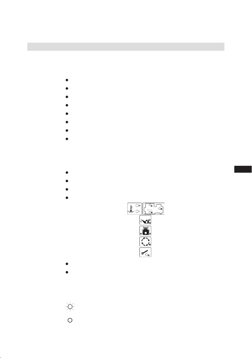
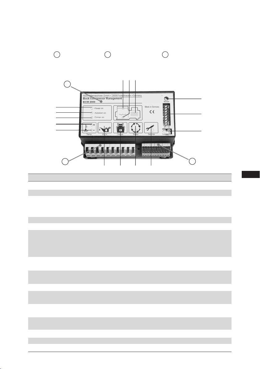
The unit has three main components:
A
- Electronic section B - Power supply section C - Control section
Altogether the unit has 8 monitoring functions: motor winding temperature, compressed gas temperature, oil temperature, oil pressure, liquid detection during start-up, compressor rotation detection,
surge guard, recommended oil change.
A
B
C
12
11
4
910
65
15
14
13
8
7
2
3
1
A
B
C
12
11
4
910
65
15
14
13
8
7
2
3
1
Item No. Designation Function
1 Mains voltage LED green for mains voltage
2 Compressor operation LED green for compressor operation
3 Automatic compressor start LED yellow for automatic compressor release. Com
pressor starts after a delay via the machine
control or lube oil pre-heating
4 Motor winding temperature LED red when temperature too high
5 Compressed gas temperature LED red when temperature too high
6 Oil temperature LED red when temperature too low
Compressor is enabled for starting only
when the lube oil is pre-heated to +25°C,
but at the latest after 30 min.
7 Temperature display + LED red comb. with item 4 / 5 / 6
8 Temperature display - temperature too high (+) or too low (-)
9 Oil pressure LED red when oil pressure too low
Delay: approx. 90 s
10 Liquid detection LED red for liquid hammers during start-up
10 Compressor rotation detection LED red when compressor does not start although
motor supplied with power
11 Surge guard LED yellow for more than 12 starts per hour
Compressor continues to operate, no stop
12 Recommended oil change LED yellow after a certain interval has been exceeded
Compressor continues to operate, no stop
13 Reset button Reset to operating function
14 Bridging switch Activates or bridges individual functions
15 PC interface For reading
}
Standard settings
Monitoring Procedure Value
Motor temperature Compressor switched off at motor overtemperature 130° C
Reset release when cooled down after motor overtemperature 120° C
Oil temperature Automatic release after the oil has pre-heated 25° C
1)
1)
or automatic release after maximum pre-heating time 30 min
Automatic shut-down of the compressor at oil overtemperature 120° C
Automatic release when cooled down after oil overtemperature 95° C
Automatic shut-down of the compressor at oil undertemperature 17° C
Discharge gas Shut-down of the compressor at hot gas overtemperature 140° C
temperature Reset release when cooled down after hot gas overtemperature 130° C
Oil differential Minimum value for oil differential pressure 0,65 bar
pressure Shut-down of the compressor when differential pressure too low 0,6 bar
2)
2)
Shut-down delay time when differential pressure too low 90s
A
A
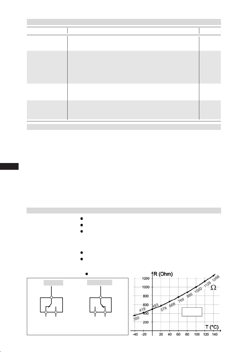
Sensor details
Discharge gas tem-
PTC sensor switching at 140 °C.
perature sensor: Resistance range 20 - 100 Ω at 15 - 50°C (value for each sensor).
Functioning principle: only slight change in resistance when heated up
below the switching point temperature, but in the switching point range
the resistance value suddenly changes by several kOhm.
Oil temperature sensor: Sensor KTY84-130 (see diagram: resistance temperature curve)
Functioning principle: resistance value changes according to the
change in oil temperature
Differential pressure switch:
∆P Reed contact, IP 65
Switching current: 30 mA, switching power: max.
30 VA; Ambient temperature: -30 … +70°C
brown
red
orange
L+
∆P good
red
orange
L+
∆P bad
brown
Adjustable settings
All the errors saved in BCM 2000 (up to 170) incl. the operating hours counter total can be read out
with a PC, the reading program on CD-ROM and the cable. In addition, the following trigger settings
can be changed on the spot depending on the prevailing conditions:
Out-of-step: Compressor blocked after every standart shut-down: 180 s
D
GB
F
E
Variable time range: 0 - 255 s
For rack operation, set this position to “0” or hide with bypass switch 7,
see pos. 7 in the chapter “error messages – information messages –
emergency operation.
Oil pressure error time: Shut-down delay (standart setting): 90 s
Variable time range: 15 - 90 s
Rotation detection: Vibration factor (standart setting): 2
Variable time range: 0 - 40
KTY84-130
6
09794-05.2012-DGbFEI

7
D
GB
F
E
09794-05.2012-DGbFEI
orange
brown
red
C
B
Connecting the unit
PTC
compressed gas
temperature sensor
PTC
motor winding
temperature sensor
oil temperature
sensor
oil pressure
sensor
oil sump
heating E1
brown
red
orange
Electrical connection
Electrical connection
General
The unit has two different connection blocks:
1) Power supply section
B
2) Control section
C
The power supply section is for connection to the machine mains voltage. It is to be integrated in the
machine control by the refrigerating engineer (qualifi ed engineer). The unit is to be integrated in fi rst
position of the safety chain. The power supply at L1-N should be identical with the switching voltage
at relay contacts 11, 12 and 14.
The control section is used for connection of the individual monitoring functions. These are normally
ready wired in the factory and prefabricated ready for operation so that no additional work is necessary here.
The whole control section (terminals 15 - 25) and all monitoring sensors, probes and
corresponding connections must not have any contact with mains voltage. Otherwise
the BCM 2000 and sensor components will be destroyed.
Electrical connection
Connecting the unit
B
C
E1 Oil sump heater
F1 Control fuse
K1.1 Auxiliary contactor
K2T Delay relay 10-60 min.,
Connection facility for external
collective error message
F Safety chain with regulating unit (thermostat)
Kx Compressor load contactor or protection
combination with motor protection switches
S1 Switch for control voltage Off / On
Electrical connection of the unit is to be carried out by a qualied electrician accor-
ding to the circuit diagramm.
Comply with the local safety regulations.
Always disconnect the machine from the power supply before and during working
on the machine.
Compare the voltage and frequency details on the nameplate with the details for
the electricity mains. Unit may only be connected up when these coincide.

D
GB
F
E
Electrical connection
ca. 10 - 40 min.
orange
brown
red
10-60 min
8
09794-05.2012-DGbFEI

9
D
GB
F
E
09794-05.2012-DGbFEI
Checking functions
Integration of additional switching and control components
• Auxiliary contactor K1.1
An auxiliary contactor K1.1 is provided to protect the contacts in the unit (max. tol. load AC
250 V / 3 A / 750 VA ind.)
• Delay relay K2T
A delay relay K2T 10 - 60 min is to be superposed so that various operating interruptions are
not indicated as fault (adjustment range approx. 10 to 60 minutes, settling time 40 min.)
• Oil sump heating E1
The compressor oil sump heater E1 is to be connected up in combination with the oil tempera-
ture function. The oil sump heater should already be running during the evacuation phase.
If the oil temperature is under +25°C,
the compressor is blocked and the
oil sump heater is running.
For oil temperatures exceeding +25°C, but at the latest after 30 min. pre-heating
heater
time the compressor is released for operation and the oil sump
switches off.
Checking the functions
General
The unit is mounted in the compressor terminal box. All monitoring sensors are connected and their
functions have been checked. A separate function check is not necessary. The following function
checks can be carried out when spare parts have been supplied or as part of troubleshooting:
Function check for compressed gas/winding/oil temperature
Function check for oil pressure
Procedure for checking the compressed gas / winding / oil temperature functions
1 Disconnect from the mains
Disconnect the temperature sensor (terminal 15, 17 or 19)
Important! Every sensor must be checked individually!
2 Insert wire bridge L1 - 5
3 Apply mains voltage
The 2 corresponding LEDs must light up after 30 s delay
4 Disconnect from the mains, remove the wire bridge (see no. 2), connect sensor (see no. 1)
5 Apply mains voltage
Unit ready

Activation / bridging the monitoring functions
Procedure for checking the oil pressure function
1 Disconnect from the mains
Disconnect the sensor (terminal 22)
2 Insert wire bridge L1 - 5
3 Apply mains voltage
The corresponding LED must light up after approx. 90 s delay
4 Disconnect from the mains, remove the wire bridge (see no. 2), connect sensor (see no. 1)
5 Apply mains voltage
Unit ready
D
GB
F
E
Activating or bridging individual monitoring functions
General
Each of the 8 possible functions can be individually activated or
bridged. The works setting is always „activated“. Every function
is numbered and allocated to the function switch with the same
number. The adjustment of the function switch is only activated
after quitting with the reset button for safety reasons. The adjustment can be made when the compressor is running or at a standstill.
No safety functions work in bridged state. Therefore use only for
emergency operation. LED ashes until function is activated again.
Bridge function
(e.g. service display)
Switch setting to the left (off)
Activate function
(e.g. service display)
Switch setting to the right (on)
Reset
LED ashes
Reset
LED off
Reset button
Function switches
Compressor starts up or continues through the machine
control
Compressor starts up or continues through the machine
control; exception: longer
power failure. operation only
released after lube oil has
pre-heated
10
09794-05.2012-DGbFEI

11
D
GB
F
E
09794-05.2012-DGbFEI
Reset, messages, emergency operation
Reset
General
Every message can be quit with reset. The procedure can be
repeated as often as necessary.
Caution! First rectify the fault, then release the compressor. After quitting the fault with the reset button,
the compressor starts up again without any delay
Quit fault (e.g. oil fault)
Compressor starts up immediately. Exception: longer
Reset
LED on LED off
power failure. operation only
released after lube oil has preheated
Reset button
Fault messages - information messages - emergency operation
General
The unit has 8 monitoring functions. These are divided into:
- 5 fault messages (compressor shutdown when triggered)
- 2 information messages (compressor not shutdown when triggered)
- 1 status message (compressor automatically released when triggered)
There are two possibilities for reactivating the messages:
a) reset to initial function (using reset button)
b) bridging the functions (emergency operation using function switch)
The unit can save several approx. 170 fault messages.
The device can save up to 170 error messages. The saved error messages can
be read via the PC interface with the special interface cable (accessory, article no.
06988) and the Bock reading program (accessory, article no. 06992).
CAUTION! Remedy fault rst, then release compressor!
No protection functions available in bridged status. Therefore only use
for emergency operation! LED ashes until function activated again.
Function switches
Reset button

Messages and emergency operation
D
GB
F
E
Display a) Reset to initial function b)
operation - no safety function)
Fault message
Compressed gas temperature
1
too high. LED ON / Compressor
OFF
Fault message
Winding temperature too high.
2
LED ON / Compressor OFF
Status message
Oil temperature too low.
3
LED ON / Compressor OFF
Possible after cooling down
to operating temperature
Reset
Compressor starts up immedi-
ately.
LED OFF
Possible after cooling down
to operating temperature
Reset
Compressor starts up immedi-
ately.
LED OFF
Reset not possible
Compressor starts automa-
tically after preheating the
lube oil to +25°C, but at
the latest after 30 min.
pre-heating time
LED - OFF / Compressor - ON
Function bridged (emergency
Possible without cooling down
to operating temperature
+
Reset
Switch 1 Off
Compressor starts up through
machine control. LED ashes
Possible without cooling down
to operating temperature
+
Reset
Switch 2 Off
Compressor starts up through
machine control. LED ashes
+
Reset
Switch 3 Off
Compressor starts up through
machine control. LED ashes
12
Status message
Oil temperature too high.
3
LED ON / Compressor OFF
Reset not possible
Compressor starts automa-
tically after cooling down.
LED - OFF / Compressor - ON
+
Reset
Switch 3 Off
Compressor starts up through
machine control. LED ashes
09794-05.2012-DGbFEI

13
D
GB
F
E
09794-05.2012-DGbFEI
Messages and emergency operation
Display a) Reset to initial function b)
operation - no safety function)
Fault message
Reset
Oil pressure too low
4
LED ON / Compressor OFF
Fault message
Combined function 1:
Liquid at start
5
LED ON / Compressor OFF
Fault message
Combined function 2:
Compressor not turning.
6
LED ON / Compressor OFF
Information message
Compressor starts up immedi-
ately.
LED OFF
Reset
Compressor starts up
immediately.
LED OFF
Reset
Compressor starts up
after fault eliminated.
LED OFF
12 starts per hour
exceeded
Function bridged (emergency
+
Reset
Switch 4 Off
Compressor starts up through
machine control. LED ashes
+
Reset
Switch 5 Off
5 + 6 are bridged. Compressor
starts up through machine control.
starts up through machine control.
LED ashes
+
Reset
Switch 6 Off
Only 6 is bridged. Compressor
LED OFF
Engine monitoring by winding temperature feeler
Surge op. too high
7
LED ON / Compressor ON
Information message
Recommended oil change
8
LED ON / Compressor ON
Reset
LED OFF
Reset to „0“
Counting starts again
Reset
LED OFF
Reset to „0“
Evaluation starts again
+
Reset
Switch 7 Off
Compressor starts up through
machine control. LED ashes
+
Reset
Switch 8 Off
Compressor starts up through
machine control. LED ashes

D
GB
F
E
Spare parts and accessories
Spare parts and accessories
General
The basic BCM 2000 unit is designed and programmed in the factory to work with the corresponding compressor. This guarantees the best possible functional reliability. When spare parts are
required, we must know the compressor type and machine number before delivering an individual
unit to ensure that it will function properly.
Overview of spare parts / accessories
Item. Designation Art. No.
1 Electronic compressor protection
Bock - BCM 2000, 230 V~ 06950
consisting of:
basic unit with microprocessor
for all possible functions, display with individual
function displays, adjusting switches for the various
functions, reset button, interface for PC
connection, power supply section, control section for
the individual functions
2b
2 Oil pressure monitoring ∆P
2 a: Delta-P screw-on part ¾“ 16 UNF 06990
(to version ID 17)
2 b: INT 250 - circuit part with lead 06989
2 c: Delta-P screw-on part M20x1,5 50225
(starting from version ID 18)
2a, 2c
3 Oil temperature monitoring
NTC screw-on temperature sensor 06947
Thread NPTF 1/8“ with lead
Lead colour: black
4 Compressed gas temperature monitoring
PTC screw-on temperature sensor 06033
Thread NPTF 1/8“ with lead
Lead colour: red-brown
5 Interface lead
for PC connection 06988
6 CD with read-out program 06992
14
09794-05.2012-DGbFEI

15
D
GB
F
E
09794-05.2012-DGbFEI
Troubleshooting
What to do, when ….
Display Possible fault causes or information message
> Check control fuse and voltage at terminals
L and N on the BCM 2000
Control voltage is ON
but no LED lights up
> Interruption (open contact) in the safety chain.
Check all integrated switches and units for continuity
LED „power on“ and „compressor on“
light up but the compressor does not turn
Fault message
> discharge end temperature too high
> Suction gas overheating too high
> Condensing temperature too high
> Bypass from pressure to suction side
1 = compressed gas temp. too high
LED ON / Compressor OFF
Fault message > Motor overload
> Undervoltage
> Control error
> Winding short, short circuit, accidental ground
> Two-phase mode
2 = winding temperature too high > Motor cooling insuffi cient
LED ON / Compressor OFF > Extremely unequal phase load
Status message
> Oil sump heating not working
> Pre-heating phase too short
Operation released at +25°C, but at the latest
3 = Oil temperature too low after 30 min. pre-heating time
LED ON / Compressor OFF
> Oil sensor is not screwed as far as it will go into the Fault
message screw-in sleeve
> Not enough oil
> Liquid coolant in compressor / in oil
> Dirt in machine / in oil
> Oil pump defect
4 = Oil pressure too low > Inadequate oil return
LED ON / Compressor OFF > Unsuitable oil grade
> Damage to bearings or power plant, wear
What to do, when ... ?

D
GB
F
E
Troubleshooting
Display Possible fault causes or information message
Fault message
> Refrigerant or oil displaced in the machine
> Check electric valve, solenoid in liquid pipe for
function and leaks
5 = liquid at start
Fault message > One or all power supply phases not connected.
> For parallel operation: Sensor possibly affected by
the operation of an adjacent compressor
(–> bypass function).
Fault message 6 is displayed although the compressor
is running:
6 = compressor not turning > Operating vibrations too low. Vibration sensor cannot
LED ON / Compressor OFF detect the compressor running due to the exception-
ally quiet operation.
> Adjust the sensor’s sensitivity (Bock service software
required for this). This position can also be temporarily
shut down without the service software by tripping
DIP switch 6. Multiple monitoring of this position
ensures that the compressor is fully monitored.
Information message > More than 12 start-ups per hour
> Faulty control or setting
> Insufcient refrigerant
> Condenser pressure control fault
> Evaporator icing
7 = Surge op. too high > E-valve problem
LED ON / Compressor ON > SL lter or dryer contaminated
Information message
> Oil change is recommended
> Filter or dryer change can be associated with
this message
8 = Recommended oil change
LED ON / Compressor ON
16
09794-05.2012-DGbFEI

17
D
GB
F
E
09794-05.2012-DGbFEI
Standard Paragraph Designation Value
EN 60730 2.2.15 Purpose of control unit: Motor protection device
6.2.6 Type of controlled load: pilot load
6.4 Reset characteristic: not automatic: type 3BH
automatic: type 3C
Software class A
Device protection class
Relevant standards
Fault memory:
The Bock BCM 2000 (v1.4) software provides the possibility of exporting the complete fault
memory of the BCM 2000 to a text le thus making a backup of it.
Procedure for backing up the fault memory:
1. A voltage of 230 V must be applied between L1 and N of the BCM 2000.
2. The BCM 2000 must be connected to a PC using the special cable.
3. Start the BCM 2000 software and wait until the fault report is read out.
4. On the “Diagnostics” screen, there is the “Export” button next to the “Retrieve” button which
makes a new readout of the BCM 2000 possible when clicked.
5. The BCM 2000 software creates a text le (“Export File”) when the “Export” button is clicked.
6. Select the destination where the text le should be saved. Input lename and conrm with
“Save”. The name of the backup le should contain the machine number, type and date.
Example: AN022334A014-HGX8-2830-4S-01012006.txt

Excellence Passion Integrity Responsibility GEA-versity
GEA Group is a global engineering company with multi-billion euro sales and operations in more
than 50 countries. Founded in 1881, the company is one of the largest providers of innovative
equipment and process technology. GEA Group is listed in the STOXX Europe 600 Index.
D
GB
F
E
GEA Refrigeration Technologies
GEA Bock GmbH
Benzstraße 7, 72636 Frickenhausen, Germany
Telephone: +49 7022 9454-0, Fax: +49 7022 9454-137
bock@gea.com, www.bock.de
18
09794-05.2012-DGbFEI © GEA Group AG. All rights reserved.
09794-05.2012-DGbFEI
 Loading...