

GEA SHG12P/110-4 L, SHG12P/75-4 SL, SHG12P/60-4 SL, SHG12P/110-4 SL, SHG22e/125-4 L Assembly Instructions Manual
...
D
GB
F
E
1
09600-08.2017-DGbF
GEA Bock Condensing Units
Assembly instructions
09600-08.2017-Gb
Translation of the original instructions
SHA(X)12P...L SHG(X)12P...L SHG(X)5...L
SHA(X)22e...L SHG(X)22e...L SHG(X)56e...L
SHA(X)34e...L SHG(X)34e...L SHG(X)6...L
SHA(X)4...L SHG(X)44e...L SHGZ(X)7...L

2
D
GB
F
E
09600-08.2017-DGbF
GEA Bock GmbH
72636 Frickenhausen
Manufacturer
Contact
GEA Bock GmbH
Benzstraße 7
72636 Frickenhausen
Germany
Telefon +49 7022 9454-0
Telefax +49 7022 9454-137
info@gea.com
www.gea.com
Read these instructions before assembly and before using the condensing unit. This will avoid misunderstandings and prevent damage. Improper assembly and use can result in serious or fatal injury.
Observe the safety instructions contained in these instructions and in the compressor instructions.
These instructions must be passed onto the end customer along with the unit in which the condensing unit is installed.
Observe also the other documentation included with the condensing unit.
About these instructions

D
GB
F
E
3
09600-08.2017-DGbF
Contents Page
1
Safety 4
1.1
Identication of safety instructions
1.2
Qualications required of personnel
1.3
Safety instructions
1.4
Intended use
2
Product description 6
2.1
Short description
2.2
Name plate
2.3
Type key
3 Areas of application 8
4
Assembly 8
4.1 Setting up
5
Maintenance 9
5.1
Preparation
5.2
Work to be carried out
6
Technical data 10
7
Dimensions and connections 13
8 Service 18
Note:
According to Commission Regulation (EU) 2015/1095 of May 5th 2015 implementing Directive
2009/125/EC of the European Parliament and of the Council with regard to ecodesign requirements
for professional condensing units, starting 2016 July 1st in the EU only products may be sold which
fulll minimum efciency requirements. These minimum efciency requirements must be documented by a certicate.
The matching certicate for your condensing unit can be created on the Internet on our software
(VAP) under http://vap.gea.com/stationaryapplication/

4
D
GB
F
E
09600-08.2017-DGbF
1.1 Identicationofsafetyinstructions:
1 | Safety
1.2 Qualicationsrequiredofpersonnel
WARNING Inadequatelyqualiedpersonnelposes theriskofaccidents,the
consequencebeingseriousor fatalinjury. Work on compressors
isthereforereservedforpersonnelwhichisqualied toworkon
pressurized refrigerant systems:
• For example, a refrigeration technician, refrigeration mechatronic
engineer. As well as professions with comparable training, which
enables personnel to assemble, install, maintain and repair
refrigeration and air-conditioning systems. Personnel must be capable
of assessing the work to be carried out and recognising any potential
dangers.
DANGER Indicatesadangeroussituationwhich,ifnotavoided,
willcauseimmediatefatalorseriousinjury.
WARNING Indicatesadangeroussituationwhich,ifnotavoided,
maycausefatalorseriousinjury.
CAUTION Indicatesadangeroussituationwhich,ifnotavoided,
maycausefairlysevereorminorinjury.
ATTENTION Indicatesasituationwhich,ifnotavoided,
may cause property damage.
INFO Importantinformationortipsonsimplifyingwork.

D
GB
F
E
5
09600-08.2017-DGbF
1 | Safety
1.4 Intended use
1.3 Safety instructions
WARNING Riskofaccidents.
Refrigerating compressors are pressurised machines and as such
call for heightened caution and care in handling.
The maximum permissible overpressure must not be exceeded,
even for testing purposes.
Riskofburns!
- Dependingontheoperatingconditions,surfacetemperaturesof
over 60°C on the discharge side or below 0°C on the suction side
can be reached.
- Avoid contact with refrigerant necessarily.
Contactwithrefrigerantcancausesevereburnsandskin
damage.
WARNING The condensing unit may not be used in potentially explosive
environments!
These assembly instructions describe the standard version of the condensing units named in the
title manufactured by GEA. The condensing unit is intended for installation in a machine (within the
EU according to the EU Directives 2006/42/EC Machinery Directive, 2014/68/EU Pressure Equipment
Directive).
Commissioning is permissible only if the condensing unit has been installed in accordance with these
assembly instructions and the entire system into which it is integrated has been inspected and approved in accordance with legal regulations.
Only refrigerants may be used which are released on
http://vap.gea.com/stationaryapplication/
Anyotheruseofthecondensingunitisprohibited!
6
D
GB
F
E
09600-08.2017-DGbF
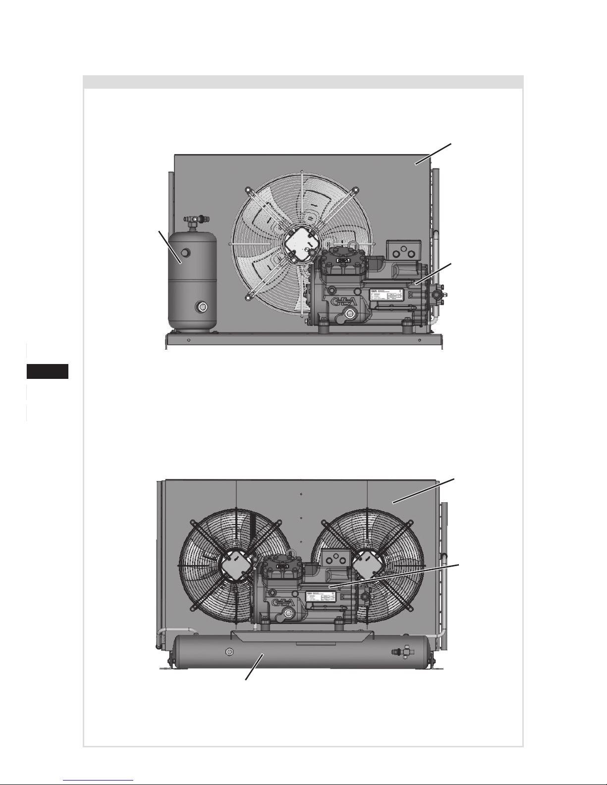
Dimension and connection values can be found in Chapter 7
2.1 Short description
2 | Product description
Condenser
Condenser
Condensing unit with vertical receiver
Condensing unit with horizontal receiver
Receiver
Receiver
Compressor
Compressor

D
GB
F
E
7
09600-08.2017-DGbF
1
2
3
SHGX34e/315-4 L
AX38125A001
/
SHG 43 e
380-
L
4 SX
2.3 Typekey (example)
¹
)
HG - Hermetic Gas-Cooled (suction gas-cooled)
²
)
X - Ester oil charge
3)
S - Stronger motor
4)
L = Aircooled condensing unit
Aircooled
4
)
Motor variant
3)
Number of poles
Swept volume
e-Series
Number of cylinders
Size
Oil charge ²
)
Series ¹
)
GEA Bock GmbH
72636 Frickenhausen, Germany
19/28
2 | Product description
2.2 Name plate (example)
1 Type designation
2 Machine number
3 ND (LP): Max. admissible operating pressure suction side
HD (HP): Max. admissible operating pressure high-pressure side

8
D
GB
F
E
09600-08.2017-DGbF
?
4 | Assembly
3 | Areas of application
4.1 Setting up
INFO Newcompressorsarefactory-lledwithinertgas(3barnitrogen).
Leave this service charge in the compressor for as long as possible and prevent the ingress of air.
Immediately after connecting the Plusbox to the refrigeration
system,closetheshut-offvalvesinthesuction,dischargelines
etc. and evacuate the compressor.
Checkthecondensingnunitfortransportdamagebeforestarting
anywork.
-
-
-
3.1 Areas of application
• The operating limits of the condensing units differ to the respective compressor.
The really operating limits can be found on the Internet on our software (VAP) under vap.gea.com.
Do not lift manually
Use lifting gear
Transport preferably via forklift truck,
alternatively bolted to a pallet
Provide adequate clearance for maintenance work.
Distance from wall to condenser minimum 300 mm.
Do not use in a dusty, damp atmosphere or a combustible
environment.

D
GB
F
E
9
09600-08.2017-DGbF
4 | Assembly
F
E
1
2
5 | Maintenance
Set up on an even surface or frame with sufcient load-bearing
capacity. Only set up on a slant after following consulting.
Preferably on vibration damper or mounting rubbers.
Sun protection: If the condensing unit is set up outdoors, it
has to be protected from direct sunlight.
5.1 Preparation
WARNING Beforestartinganyworkonthecompressor:
Switch off the compressor and secure it to prevent a restart.
Relieve compressor of system pressure.
Preventairfrominltratingthesystem!
After maintenance has been performed:
Connect safety switch.
Evacuate compressor.
Releaseswitch-onlock.
5.2 Worktobecarriedout
To avoid system-related problems, the following service work must be carried out on the Plusbox:
Cleaning: A dirty condenser leads to performance losses!
Visual inspections and possible condenser cleaning therefore required on a monthly base.
We recommend using compressed air and a soft brush for cleaning.
Further maintenance work in accordance with the instructions for assembly on the compressor.

10
D
GB
F
E
09600-08.2017-DGbF
6 | Technical Data
Type
Fan/Condenser(230V-1-50Hz) Receiver
capacity
Weight
Max.
workingcurrent
50 Hz
Max.
power consumption
50 Hz
Airow
50 Hz
A W
m³/h
Ltr. kg
SHG12P/60-4 SL 1,22 280 3550 6,0 88
SHG12P/75-4 L 1,22 280 3550 6,0 88
SHG12P/75-4 SL 1,22 280 3550 6,0 91
SHG12P/90-4 L 1,22 280 3550 6,0 91
SHG12P/90-4 SL 1,22 280 3550 6,0 94
SHG12P/110-4 L 1,22 280 3550 6,0 94
SHG12P/110-4 SL 1,22 280 3550 6,0 94
SHG22e/125-4 L 1,22 280 3550 6,0 123
SHG22e/125-4 SL 1,22 280 3550 6,0 127
SHG22e/160-4 L 1,22 280 3550 6,0 127
SHG22e/160-4 SL 1,22 280 3550 6,0 128
SHG22e/190-4 L 2,50 580 5950 8,0 149
SHG22e/190-4 SL 2,50 580 5950 8,0 150
SHG34e/215-4 L 2,50 580 5950 8,0 167
SHG34e/215-4 SL 2,50 580 5950 10,0 178
SHG34e/255-4 L 2,50 580 5950 8,0 166
SHG34e/255-4 SL 2,50 580 5950 10,0 178
SHG34e/315-4 L 2,50 580 5950 8,0 169
SHG34e/315-4 SL 2 x 2,50 2 x 500 8740 14,0 180
SHG34e/380-4 L 2 x 2,50 2 x 500 8740 14,0 176
SHG34e/380-4 SL 2 x 2,50 2 x 500 9490 14,0 185
D
GB
F
E
11
09600-08.2017-DGbF
6 | Technical Data
Type
Fan/Condenser(230V-1-50Hz) Receiver
capacity
Weight
Max.
workingcurrent
50 Hz
Max.
power consumption
50 Hz
Airow
50 Hz
A W
m³/h
Ltr. kg
SHG44e/475-4 L 2 x 2,50 2 x 500 9490 14,0 255
SHG44e/475-4 SL 4 x 2,50 4 x 500 16280 14,0 310
SHG44e/565-4 L 2 x 2,50 2 x 500 9490 14,0 256
SHG44e/565-4 SL 4 x 2,50 4 x 500 14880 23,0 326
SHG44e/665-4 L 4 x 2,50 4 x 500 16280 23,0 318
SHG44e/665-4 SL 4 x 2,50 4 x 500 14880 23,0 324
SHG44e/770-4 L 4 x 2,50 4 x 500 14880 23,0 396
SHG44e/770-4 SL 4 x 3,00 4 x 680 23850 35,0 419
SHG5/830-4 L 4 x 2,50 4 x 500 14880 23,0 356
SHG5/830-4 SL 4 x 3,00 4 x 680 23850 35,0 385
SHG5/945-4 L 4 x 2,50 4 x 500 14880 23,0 360
SHG5/945-4 SL 4 x 3,00 4 x 680 23850 35,0 386
SHG56e/850-4 L 4 x 2,50 4 x 500 14880 23,0 393
SHG56e/850-4 SL 4 x 3,00 4 x 680 23850 35,0 406
SHG56e/995-4 L 4 x 3,00 4 x 680 23850 23,0 398
SHG56e/995-4 SL 4 x 3,00 4 x 680 23850 35,0 407
SHG56e/1155-4 L 4 x 3,00 4 x 680 23850 23,0 396
SHG56e/1155-4 SL 4 x 3,00 4 x 680 21210 35,0 405
SHG6/1240-4 L 4 x 3,00 4 x 680 23850 23,0 398
SHG6/1240-4 SL 4 x 3,00 4 x 680 21210 35,0 407
SHG6/1410-4 L 4 x 3,00 4 x 680 23850 23,0 396

12
D
GB
F
E
09600-08.2017-DGbF
6 | Technical Data
Type
Fan/Condenser(230V-1-50Hz) Receiver
capacity
Weight
Max.
workingcurrent
50 Hz
Max.
power consumption
50 Hz
Airow
50 Hz
A W
m³/h
Ltr. kg
SHA12P/60-4 L 1,22 280 3550 6,0 92
SHA12P/75-4 L 1,22 280 3550 6,0 93
SHA12P/90-4 L 1,22 280 3550 6,0 95
SHA12P/110-4 L 1,22 280 3550 6,0 98
SHA22e/125-4 L 1,22 280 3550 6,0 129
SHA22e/160-4 L 1,22 280 3270 6,0 134
SHA22e/190-4 L 2,50 580 5950 8,0 155
SHA34e/215-4 L 2,50 580 5950 8,0 173
SHA34e/255-4 L 2,50 580 5950 8,0 172
SHA34e/315-4 L 2,50 580 5950 8,0 175
SHA34e/380-4 L 2 x 2,50 2 x 500 8740 14,0 182
SHA4/465-4 L 2 x 2,50 2 x 500 9490 14,0 245
SHA4/555-4 L 2 x 2,50 2 x 500 9490 14,0 246
SHA4/650-4 L 4 x 2,50 4 x 500 16280 23,0 307

D
GB
F
E
13
09600-08.2017-DGbF
7 | Dimensions and connections
SHG
Type
Dimensions
A B C D E
mm
SHG12P/60-4 SL 885 860 630 570 650
SHG12P/75-4 L 885 860 630 570 650
SHG12P/75-4 SL 885 860 630 570 650
SHG12P/90-4 L 885 860 630 570 650
SHG12P/90-4 SL 885 860 630 570 650
SHG12P/110-4 L 885 860 630 570 650
SHG12P/110-4 SL 885 860 630 570 650
Anschlüsse /
Connections
SV
Saugabsperrventil, Rohr (L)*
mm / Zoll
mm / inch
22 – 7/8"
Suction line valve, tube (L)*
FLA
Flüssigkeitsaustritt, Rohr (L)*
mm / Zoll
mm / inch
12- 1/2"
Liquid outlet, tube (L)*
Y1
Anschluss Flüssigkeitsseite, absperrbar
Zoll / inch 7/16" UNF
Connection liquid side, lockable
Y2
Anschluss Flüssigkeitsseite, nicht absperrbar
Zoll / inch 7/16" UNF
Connection liquid side, not lockable
(L)* = Lötanschluss
(L)* = Brazing connection
Weitere Anschlüsse siehe Ma ßzeichnung Verdichter
Further connections see dimensional drawing compressor
Änderungen vorbehalten
Subject to change without notice
F
E
D
1
2
34
5
6
78
SV
Y1 FLA
Y2
D
E
A
B
C
Weitere Anschlüsse siehe Maßzeichnung Verdichter
Further connections see dimensional drawing compressor
Änderungen vorbehalten
Subject to change w ithout notice
Anschlüsse /
Connections
SHG44e/
475-4 S
SHG44e/
565-4 S
665-4 (S)
770-4 (S)
SV
Saugabsperrventil, Rohr (L)*
mm / Zoll
mm / inch
35 – 1 3/8" 42 – 1 5/8"
Suction line valve, tube (L)*
FLA
Flüssigkeitsaustritt, Rohr (L)*
mm / Zoll
mm / inch
16 – 5/8" 22 – 7/8"
Liquid outlet, tube (L)*
SI
Anschluss Sicherheitsventil
Zoll / inch 1/2" NPTF
Connection safety valve
Y1
Anschluss Flüssigkeitsseite, absperrbar
Zoll / inch 7/16" UNF
Connection liquid side, lockable
Y2
Anschluss Flüssigkeitsseite, nicht absperrbar
Zoll / inch 7/16" UNF
Connection liquid side, not lockable
(L)* = Lötanschluss
(L)* = Brazing connection
1
2
34
5
6
78
FLA
SV
SI
Y2
Y1
C
B
A
D
E

14
D
GB
F
E
09600-08.2017-DGbF
7 | Dimensions
SHG
Type
Dimensions
A B C D E
mm
SHG22e/125-4 L 885 860 630 570 650
SHG22e/125-4 SL 885 860 630 570 650
SHG22e/160-4 L 885 860 630 570 650
SHG22e/160-4 SL 885 860 630 570 650
SHG22e/190-4 L 1085 1060 745 570 650
SHG22e/190-4 SL 1085 1060 745 570 650
SHG34e/215-4 L 1085 1060 745 570 650
SHG34e/215-4 SL 1085 1060 745 570 650
SHG34e/255-4 L 1085 1060 745 570 650
SHG34e/255-4 SL 1085 1060 745 570 650
SHG34e/315-4 L 1085 1060 745 570 650
SHG34e/315-4 SL 1220 1140 700 750 890
SHG34e/380-4 L 1220 1140 700 750 890
SHG34e/380-4 SL 1220 1140 800 750 890
SHG44e/475-4 L 1225 1140 800 750 890
SHG44e/475-4 SL 1300 1140 1310 750 890
SHG44e/565-4 L 1225 1140 800 750 890
SHG44e/565-4 SL 1300 1140 1310 750 890
SHG44e/665-4 L 1300 1140 1310 750 890
SHG44e/665-4 SL 1300 1140 1310 750 890
SHG44e/770-4 L 1300 1140 1310 750 890
SHG44e/770-4 SL 1300 1140 1610 750 890
SHG5/830-4 L 1300 1140 1310 750 890
SHG5/830-4 SL 1300 1140 1610 750 890
SHG5/945-4 L 1300 1140 1310 750 890
SHG5/945-4 SL 1300 1140 1610 750 890
SHG56e/850-4 L 1250 1140 1307 750 890
SHG56e/850-4 SL 1250 1140 1606 750 890
SHG56e/995-4 L 1250 1140 1606 750 890
SHG56e/995-4 SL 1250 1140 1606 750 890
SHG56e/1155-4 L 1250 1140 1606 750 890
SHG56e/1155-4 SL 1250 1140 1606 750 890
SHG6/1080-4 L 1300 1140 1610 750 890
SHG6/1080-4 SL 1300 1140 1610 750 890
SHG6/1240-4 L 1300 1140 1610 750 890

D
GB
F
E
15
09600-08.2017-DGbF
7 | Dimensions
SHG / SHGZ / SHA
Type
Dimensions
A B C D E
mm
SHG6/1240-4 SL 1300 1140 1610 750 890
SHG6/1410-4 L 1300 1140 1610 750 890
SHG6/1410-4 SL 1300 1140 1610 750 890
SHGZ7/1620-4 L 1300 1140 1610 750 1090
SHGZ7/1860-4 L 1300 1140 1610 750 1090
SHGZ7/2110-4 L 1300 1140 1610 750 1090
SHA12P/60-4 L 885 860 630 570 650
SHA12P/75-4 L 885 860 630 570 650
SHA12P/90-4 L 885 860 630 570 650
SHA12P/110-4 L 885 860 630 570 650
SHA22e/125-4 L 885 860 630 570 650
SHA22e/160-4 L 885 860 630 570 650
SHA22e/190-4 L 1085 1060 745 570 650
SHA34e/215-4 L 1085 1060 745 570 650
SHA34e/255-4 L 1085 1060 745 570 650
SHA34e/315-4 L 1085 1060 745 570 650
SHA34e/380-4 L 1220 1140 700 750 890
SHA4/465-4 L 1220 1140 800 750 890
SHA4/555-4 L 1220 1140 800 750 890
SHA4/650-4 L 1300 1140 1310 750 890

16
D
GB
F
E
09600-08.2017-DGbF
7 | Connections
SHG
Type
Connections 1
SV FLA SI Y1 Y2
mm I Inch mm I Inch Inch Inch Inch
SHG12P/60-4 SL 16 / 5/
8
12 / 1/
2
-
7
/16 UNF
7
/16 UNF
SHG12P/75-4 L 16 / 5/
8
12 / 1/
2
-
7
/16 UNF
7
/16 UNF
SHG12P/75-4 SL 16 / 5/
8
12 / 1/
2
-
7
/16 UNF
7
/16 UNF
SHG12P/90-4 L 16 / 5/
8
12 / 1/
2
-
7
/16 UNF
7
/16 UNF
SHG12P/90-4 SL 16 / 5/
8
12 / 1/
2
-
7
/16 UNF
7
/16 UNF
SHG12P/110-4 L 16 / 5/
8
12 / 1/
2
-
7
/16 UNF
7
/16 UNF
SHG12P/110-4 SL 16 / 5/
8
12 / 1/
2
-
7
/16 UNF
7
/16 UNF
SHG22e/125-4 L 22 / 7/
8
12 / 1/
2
-
7
/16 UNF
7
/16 UNF
SHG22e/125-4 SL 22 / 7/
8
12 / 1/
2
-
7
/16 UNF
7
/16 UNF
SHG22e/160-4 L 22 / 7/
8
12 / 1/
2
-
7
/16 UNF
7
/16 UNF
SHG22e/160-4 SL 22 / 7/
8
12 / 1/
2
-
7
/16 UNF
7
/16 UNF
SHG22e/190-4 L 22 / 7/
8
12 / 1/
2
1
/2 NPTF
7
/16 UNF
7
/16 UNF
SHG22e/190-4 SL 22 / 7/
8
12 / 1/
2
1
/2 NPTF
7
/16 UNF
7
/16 UNF
SHG34e/215-4 L 28 / 1 1/
8
12 / 1/
2
1
/2 NPTF
7
/16 UNF
7
/16 UNF
SHG34e/215-4 SL 28 / 1 1/
8
16 / 5/
8
1
/2 NPTF
7
/16 UNF
7
/16 UNF
SHG34e/255-4 L 28 / 1 1/
8
12 / 1/
2
1
/2 NPTF
7
/16 UNF
7
/16 UNF
SHG34e/255-4 SL 28 / 1 1/
8
16 / 5/
8
1
/2 NPTF
7
/16 UNF
7
/16 UNF
SHG34e/315-4 L 28 / 1 1/
8
12 / 1/
2
1
/2 NPTF
7
/16 UNF
7
/16 UNF
SHG34e/315-4 SL 28 / 1 1/
8
16 / 5/
8
1
/2 NPTF
7
/16 UNF
7
/16 UNF
SHG34e/380-4 L 28 / 1 1/
8
16 / 5/
8
1
/2 NPTF
7
/16 UNF
7
/16 UNF
SHG34e/380-4 SL 28 / 1 1/
8
16 / 5/
8
1
/2 NPTF
7
/16 UNF
7
/16 UNF
SHG44e/475-4 L 35 / 1 3/
8
16 / 5/
8
1
/2 NPTF
7
/16 UNF
7
/16 UNF
SHG44e/475-4 SL 35 / 1 3/
8
16 / 5/
8
1
/2 NPTF
7
/16 UNF
7
/16 UNF
SHG44e/565-4 L 35 / 1 3/
8
16 / 5/
8
1
/2 NPTF
7
/16 UNF
7
/16 UNF
SHG44e/565-4 SL 42 / 1 5/
8
22 / 7/
8
1
/2 NPTF
7
/16 UNF
7
/16 UNF
SHG44e/665-4 L 42 / 1 5/
8
22 / 7/
8
1
/2 NPTF
7
/16 UNF
7
/16 UNF
SHG44e/665-4 SL 42 / 1 5/
8
22 / 7/
8
1
/2 NPTF
7
/16 UNF
7
/16 UNF
SHG44e/770-4 L 42 / 1 5/
8
22 / 7/
8
1
/2 NPTF
7
/16 UNF
7
/16 UNF
SHG44e/770-4 SL 42 / 1 5/
8
22 / 7/
8
1
/2 NPTF
7
/16 UNF
7
/16 UNF
SHG5/830-4 L 42 / 1 5/
8
22 / 7/
8
1
/2 NPTF
7
/16 UNF
7
/16 UNF
SHG5/830-4 SL 42 / 1 5/
8
22 / 7/
8
1
/2 NPTF
7
/16 UNF
7
/16 UNF
SHG5/945-4 L 54 / 2 1/
8
22 / 7/
8
1
/2 NPTF
7
/16 UNF
7
/16 UNF
SHG5/945-4 SL 54 / 2 1/
8
22 / 7/
8
1
/2 NPTF
7
/16 UNF
7
/16 UNF
SHG56e/850-4 L 54 / 2 1/
8
22 / 7/
8
1
/2 NPTF
7
/16 UNF
7
/16 UNF
SHG56e/850-4 SL 54 / 2 1/
8
22 / 7/
8
1
/2 NPTF
7
/16 UNF
7
/16 UNF

D
GB
F
E
17
09600-08.2017-DGbF
7 | Connections
SV = Suction line shut off valve
FLA = Liquid outlet
SI = Connection safety valve
Y1 = Connection liquid side, lockable
Y2 = Connection liquid side, not lockable
Y3 =
Schrader-Connection speed controller for fan
1 Further compressor connections can be
found in the assembly instructions of the
compressor
SHG
SHGZ
SHA
Type
Connections 1
SV FLA SI Y1 Y2
mm I Inch mm I Inch Inch Inch Inch
SHG56e/995-4 L 54 / 2 1/
8
22 / 7/
8
1
/2 NPTF
7
/16 UNF
7
/16 UNF
SHG56e/995-4 SL 54 / 2 1/
8
22 / 7/
8
1
/2 NPTF
7
/16 UNF
7
/16 UNF
SHG56e/1155-4 L 54 / 2 1/
8
22 / 7/
8
1
/2 NPTF
7
/16 UNF
7
/16 UNF
SHG56e/1155-4 SL 54 / 2 1/
8
22 / 7/
8
1
/2 NPTF
7
/16 UNF
7
/16 UNF
SHG6/1080-4 L 54 / 2 1/
8
22 / 7/
8
1
/2 NPTF
7
/16 UNF
7
/16 UNF
SHG6/1080-4 SL 54 / 2 1/
8
22 / 7/
8
1
/2 NPTF
7
/16 UNF
7
/16 UNF
SHG6/1240-4 L 54 / 2 1/
8
22 / 7/
8
1
/2 NPTF
7
/16 UNF
7
/16 UNF
SHG6/1240-4 SL 54 / 2 1/
8
22 / 7/
8
1
/2 NPTF
7
/16 UNF
7
/16 UNF
SHG6/1410-4 L 54 / 2 1/
8
22 / 7/
8
1
/2 NPTF
7
/16 UNF
7
/16 UNF
SHG6/1410-4 SL 54 / 2 1/
8
22 / 7/
8
1
/2 NPTF
7
/16 UNF
7
/16 UNF
SHGZ7/1620-4 R...L 54 / 2 1/
8
22 / 7/
8
1
/2 NPTF
7
/16 UNF
7
/16 UNF
SHGZ7/1860-4 R...L 54 / 2 1/
8
22 / 7/
8
1
/2 NPTF
7
/16 UNF
7
/16 UNF
SHGZ7/2110-4 R...L 54 / 2 1/
8
22 / 7/
8
1
/2 NPTF
7
/16 UNF
7
/16 UNF
SHA12P/60-4 L 12 / 1/
2
12 / 1/
2
-
7
/16 UNF
7
/16 UNF
SHA12P/75-4 L 12 / 1/
2
12 / 1/
2
-
7
/16 UNF
7
/16 UNF
SHA12P/90-4 L 12 / 1/
2
12 / 1/
2
-
7
/16 UNF
7
/16 UNF
SHA12P/110-4 L 12 / 1/
2
12 / 1/
2
-
7
/16 UNF
7
/16 UNF
SHA22e/125-4 L 16 / 5/
8
12 / 1/
2
-
7
/16 UNF
7
/16 UNF
SHA22e/160-4 L 16 / 5/
8
12 / 1/
2
-
7
/16 UNF
7
/16 UNF
SHA22e/190-4 L 16 / 5/
8
12 / 1/
2
-
7
/16 UNF
7
/16 UNF
SHA34e/215-4 L 22 / 7/
8
12 / 1/
2
1
/2 NPTF
7
/16 UNF
7
/16 UNF
SHA34e/255-4 L 22 / 7/
8
12 / 1/
2
1
/2 NPTF
7
/16 UNF
7
/16 UNF
SHA34e/315-4 L 22 / 7/
8
12 / 1/
2
1
/2 NPTF
7
/16 UNF
7
/16 UNF
SHA34e/380-4 L 22 / 7/
8
16 / 5/
8
1
/2 NPTF
7
/16 UNF
7
/16 UNF
SHA4/465-4 L 35 / 1 3/
8
16 / 5/
8
1
/2 NPTF
7
/16 UNF
7
/16 UNF
SHA4/465-4 L 35 / 1 3/
8
16 / 5/
8
1
/2 NPTF
7
/16 UNF
7
/16 UNF
SHA4/465-4 L 35 / 1 3/
8
22 / 7/
8
1
/2 NPTF
7
/16 UNF
7
/16 UNF

18
D
GB
F
E
09600-08.2017-DGbF
Dear customer,
GEA compressors are top-quality, reliable and service-friendly quality products.
If you have any questions about installation, operation and accessories, please contact our technical
service or specialist wholesaler and/or our representative. The GEA service team can be contacted
by phone with a toll-free hotline 00 800 / 800 000 88 or via e-mail:
info@gea.com
Yours faithfully
GEABockGmbH
Benzstraße 7
72636Frickenhausen
Germany
8 | Service

D
GB
F
E
19
09600-08.2017-DGbF

20
D
GB
F
E
09600-08.2017-DGbF
We live our values.
Excellence • Passion • Integrity • Responsibility • GEA-versity
GEA Bock GmbH
Benzstraße 7
72636 Frickenhausen, Germany
Phone +49 (0)7022 9454-0
Fax +49 (0)7022 9454-137
info@gea.com
gea.com
GEA Group is a global engineering company with multi-billion euro sales and operations in more
than 50 countries. Founded in 1881, the company is one of the largest providers of innovative
equipment and process technology. GEA Group is listed in the STOXX® Europe 600 index.
 Loading...