

Page 1
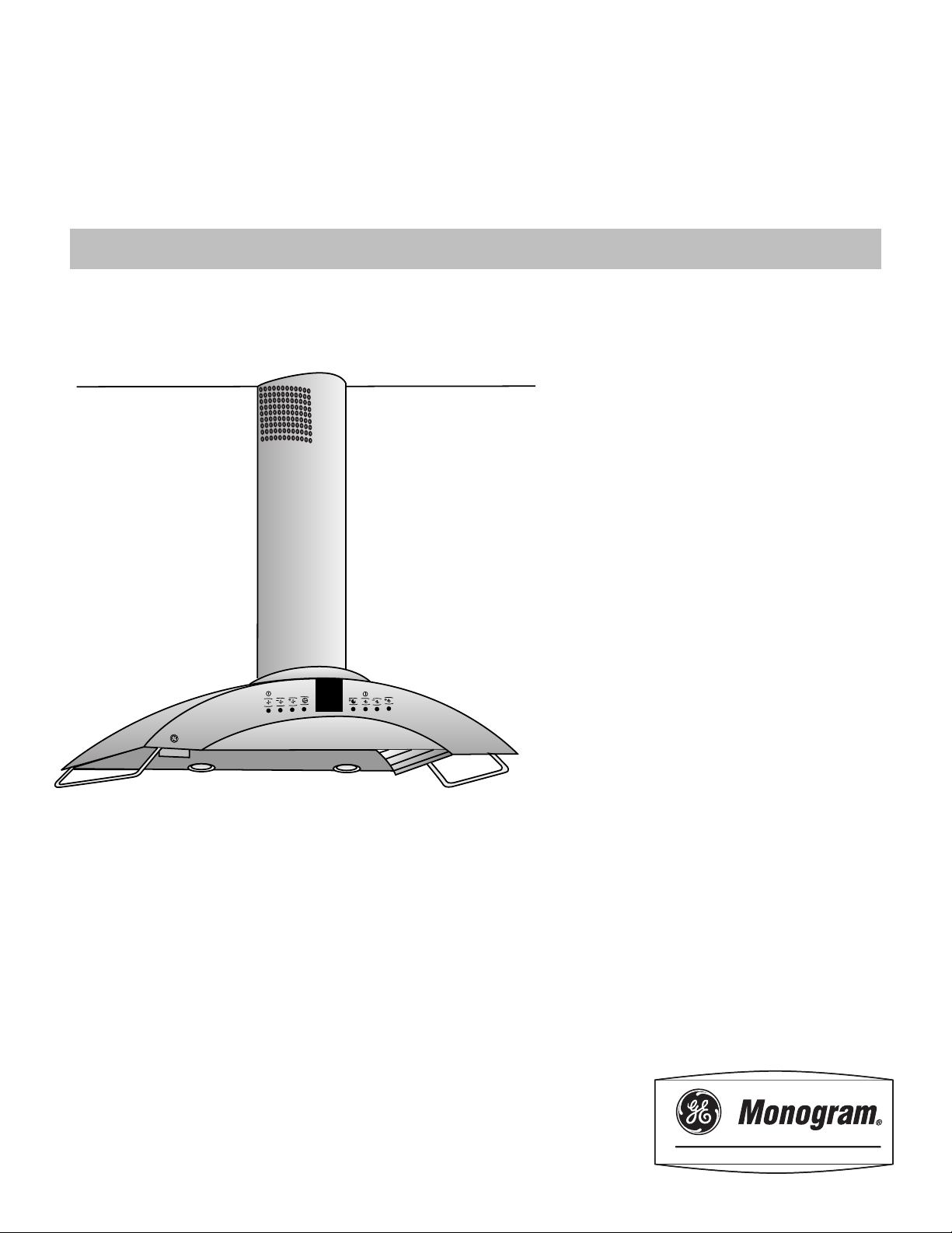
Installation
Instructions
If you have questions, call 800.GE.CARES or visit our website at: www.monogram.com
ZXR758 and ZXR7510
Recirculating Accessories
For Model ZV750, Vent Hood
M
o
n
o
g
r
a
m
Page 2
Installation Preparation
BEFORE YOU BEGIN
Read these instructions completely and carefully.
• IMPORTANT – Save these instructions for
local inspector’s use.
• IMPORTANT – Observe all governing
codes and ordinances.
• Note to Installer – Be sure to leave these instruc-
tions with the Consumer.
• Note to Consumer – Keep these instructions with
your Owner’s Manual for future reference.
• Skill Level – Installation of this appliance requires
basic mechanical and electrical skills.
• Completion time – 1 to 3 hours.
• Proper installation is the responsibility of the installer.
• Product failure due to improper installation is not
covered under the Warranty.
For Monogram local service in your area,
1.800.444.1845.
For Monogram service in Canada, call
1-.888.880.3030.
For Monogram Parts and Accessories, call
1.800.626.2002.
CAUTION:
Due to the weight and size of this vent hood and to
reduce the risk of personal injury or damage to the
product, TWO PEOPLE ARE REQUIRED FOR
PROPER INSTALLATION.
WARNING:
To reduce the risk of fire or electrical shock, do not use
this hood with any external solid-state speed control
device. Any such alteration from original factory wiring
could result in damage to the unit and/or create an
electrical safety hazard.
WARNING:
TO REDUCE THE RISK OF FIRE, ELECTRICAL
SHOCK OR INJURY TO PERSONS, OBSERVE
THE FOLLOWING:
A. Use this unit only in the manner intended by the
manufacturer. If you have any questions, contact the
manufacturer.
B. Before servicing or cleaning unit, switch power off
at the service panel and lock service panel to prevent
power from being switched on accidentally. If the
service panel cannot be locked, fasten a tag or
prominent warning label to the panel.
For general ventilating use only. Do not use to
exhaust hazardous or explosive materials or vapors.
Structural framing, installation work and electrical
wiring must be done by qualified person(s). In
accordance with all applicable codes and standards
including fire-rated construction.
Sufficient air is needed for proper combustion
and exhausting of gases through the flue (chimney)
of fuel burning equipment to prevent back drafting.
Follow the heating equipment manufacturer’s
guideline and safety standards such as those
published by the National Fire Protection Association
(NFPA), and the American Society for Heating,
Refrigeration and Air Conditioning Engineers
(ASHRAE), and the local code authorities.
Local codes vary. Installation electrical connections
and grounding must comply with applicable codes.
In the absence of local codes, the vent should be
installed in accordance with National Electrical
Code ANSI/NFPA 70-1990 or latest edition.
CONTENTS
Installation Preparation
Required Accessories .................................................. 3
Product Dimensions ................................................... 3
Duct Cover Accessories .............................................. 4
Power Supply .............................................................. 4
Tools and Materials Required .................................... 4
Remove Packaging, Check Contents ......................... 5
Installation Instructions
Step 1, Determine Installation Location ................... 6
Step 2, Install Mouning Brackets ............................... 6
Step 3, Install the Hood ............................................. 7
Step 4, Size Duct Piece ............................................... 7
Step 5, Install Air Deflector Assembly ....................... 7
Step 6, Connect Electrical .......................................... 8
Step 7, Install Duct Covers and Utility Bars .............. 8
Step 8, Install Filters ................................................... 9
Step 9, Finalize Installation ........................................ 9
2
Page 3
Installation Preparation
REQUIRED ACCESSORIES
This book provides step by step instructions to install the
Monogram ZV750 wall mounted hood for recirculating
operation.
• One of the following accessory kits is required for
non-vented wall mounted installations of model ZV750.
Choose the correct kit according to ceiling heights:
ZXR758 – For 8 to 9 ft. ceiling height.
ZXR7510 – For 9 to 10 ft. ceiling height.
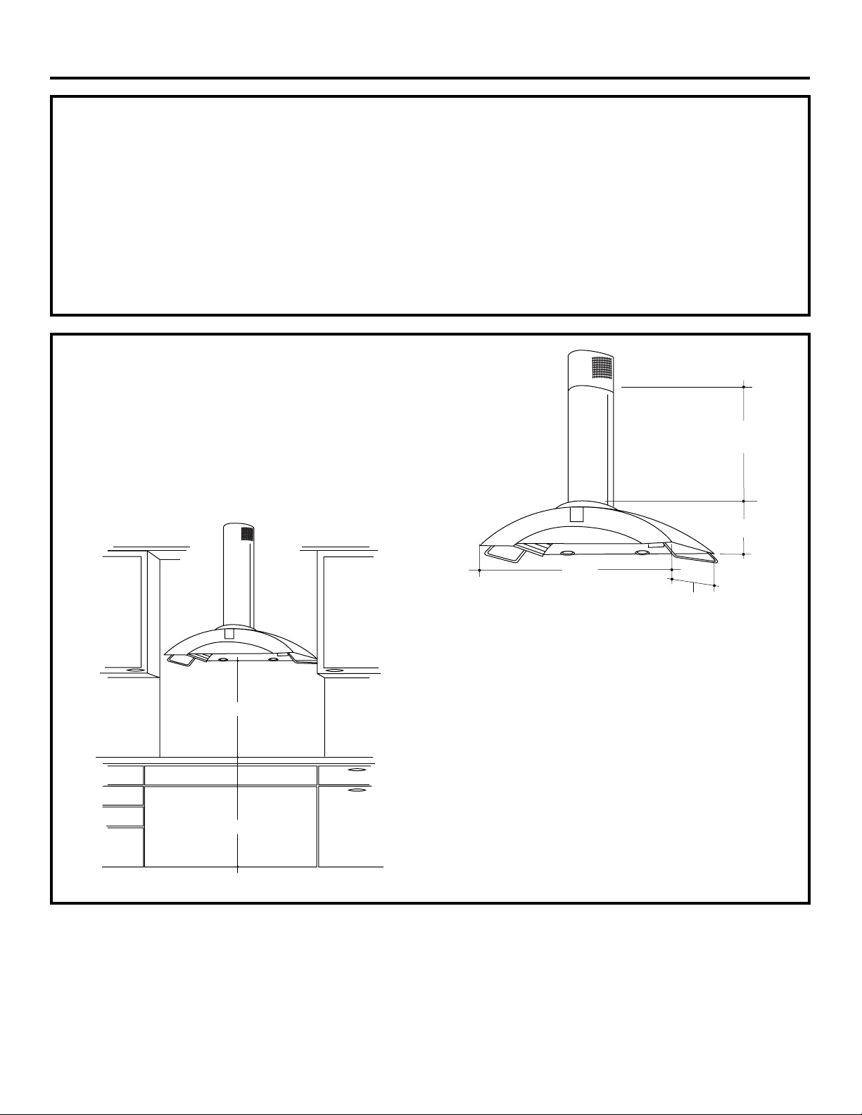
PRODUCT DIMENSIONS
The vent hood must be installed 24" min. and 30" max.
above the cooking surface. 25-1/2" is recommended for
best performance and to insure that the duct cover
meets the ceiling. The cooking surface should be at least
36” above the floor. Installation will be easier if the vent
hood is installed before the cooktop and countertop is
installed.
• Order the required accessory at the same time as the
vent hood and have on site before installation.
• Each kit includes decorative duct cover, air deflector
and charcoal filters.
*Height
to Ceiling
8-1/4"
*25-1/2" Recommended
36" Min.
34-5/8"
21-5/8"
* ZXR758
26-1/4" for 8 ft. Ceiling
38-1/4" for 9 ft. Ceiling
ZXR7510
34-1/4" to 50-1/4" for
9 ft. to 10 ft. Ceiling
* The distance between the cooking surface and the bottom of the
hood must be at least 24” and up to 30” The 25-1/2” recommended
installation height, above the standard 36” countertop, will insure
duct cover fit to the ceiling.
3
Page 4
Installation Preparation
DUCT COVER ACCESSORIES
A duct cover accessory is required for recirculating
operation. Use this chart to determine which
accessory is required for your ceiling height.
ZV750SY Installation Heights
Actual
Ceiling
Height
7′ 11″
8′ 0″
8′ 1″
8′ 2″
8′ 3″
8′ 4″
8′ 5″
8′ 6″
8′ 7″
8′ 8″
8′ 9″
8′ 10″
8′ 11″
9′ 0″
9′ 1″
9′ 2″
9′ 3″
9′ 4″
9′ 5″
9′ 6″
9′ 7″
9′ 8″
9′ 9″
9′ 10″
9′ 11″
10′ 0″
* Based on 36″ countertop height.
* Possible Hood
Installation Height
24-1/2″
25-1/2″
25-1/2″ to 26-1/2″
25-1/2″ to 27-1/2″
25-1/2″ to 28-1/2″
25-1/2″ to 29-1/2″
25-1/2″ to 30″
25-1/2″ to 30″
25-1/2″ to 30″
25-1/2″ to 30″
25-1/2″ to 30″
25-1/2″ to 30″
25-1/2″ to 30″
25-1/2″ to 30″
25-1/2″ to 30″
25-1/2″ to 30″
25-1/2″ to 30″
25-1/2″ to 30″
25-1/2″ to 30″
25-1/2″ to 30″
25-1/2″ to 30″
25-1/2″ to 30″
25-1/2″ to 30″
25-1/2″ to 30″
25-1/2″ to 30″
25-1/2″ to 30″
Recirculating
Accessory
ACCESSORY ZXR758C
ACCESSORY ZXR7510C
POWER SUPPLY
IMPORTANT – (Please read carefully)
WARNING:
FOR PERSONAL SAFETY, THIS APPLIANCE MUST
BE PROPERLY GROUNDED.
Remove house fuse or open circuit breaker before
beginning installation.
Do not use an extension cord or adapter plug with
this appliance. Follow National Electrical Code or
prevailing local codes and ordinances.
Electrical supply
This vent hood must be supplied with 120V, 60Hz,
and connected to an individual, properly grounded
branch circuit, and protected by a 15 or 20 amp
circuit breaker or time delay fuse.
• Wiring must be 2 wire with ground.
• If the electrical supply does not meet the above
requirements, call a licensed electrician before
proceeding.
• Route house wiring as close to the installation
location as possible. Wiring should enter at least 4"
above the bracket on the right side.
• Connect the wiring to the house wiring in
accordance with local codes.
Grounding instructions
The grounding conductor must be connected to
a ground metal, permanent wiring system, or an
equipment-grounding terminal or lead on the hood.
WARNING: The improper connection
of the equipment-grounding conductor can result
in a risk of electric shock. Check with a qualified
electrician or service representative if you are in
doubt whether the appliance is properly grounded.
ZV750SY Duct Cover Dimensions
Hood and
Accessory
ZXR758C
ZXR7510C
A
18-7/8″
18-7/8″
B
22-13/16″
34-5/8″
9-1/4"
A
11-7/8"
TOOLS AND MATERIALS
B
REQUIRED
• Tape measure
• Knife
• Spirit level
• Wire cutter/stripper
• Wire nuts
• Electric drill and
appropriate bits
• Phillips and flat blade
screwdrivers
• Hammer
• Pliers
• Center punch
4
(NOT SUPPLIED)
• 10 mm Hex wrench/socket
• Safety glasses
• Duct tape
• Gloves to protect against sharp
edges
• 120V 60Hz. 15 or 20 Amp, 2 wire
with ground. Properly grounded
branch circuit.
• Strain relief for junction cover.
• 6" round duct, length to suit
installation.
Page 5

Installation Preparation
Mounting
Screw
Shipping Board
Mounting
Screw
Knockout
Junction
Box
REMOVE THE PACKAGING
The vent hood is shipped secured to a shipping
board with 4 screws.
• Remove the duct cover, parts box and styrofoam
packaging.
• Lift the hood out of the box, using hand grips on
both sides of the shipping board.
• Remove and properly discard the plastic wrapping.
Mounting Screw
Shipping Board
Check Installation Hardware
Locate the hardware accessory box packed with the
hood and check contents.
• Locate and remove 2 screws at the top of the
assembly and 2 screws inside the hood behind the
filter guides on the left and right sides. Discard the
shipping board.
• Remove junction box cover.
• Remove knockout from junction box.
• Install strain relief onto junction box.
• Drill 1/8" Pilot Holes For Mounting Brackets.
• Drill 1/8" Pilot Holes.
Align edge 25-1/2" above Cooking Surface.
2-5/32"
C
L
5-7/8"
C
L
26-14" to 8 ft. Ceiling
38-1/4" to 9 ft. Ceiling
38-1/4" to 50-1/4" For
9ft. to 10 ft. Ceiling
Using Optional Accessory
ZX10SY Duct Cover
13-9/16"
3 Stainless
Steel Grease
Filters
17-5/16"
C
L
• Drill 1/8" Pilot Holes.
3-15/16"
10 Wood
Screws
10 Metal Wall
2 Large
Flat Washers
Duct Cover Bracket
(not required for
recirculating operation)
2 Side Bars with 4 Machine Screws
Fasteners
2 Mounting Brackets
Decorative
Duct
Covers
2 Phillips Head
Decorative Screws
Wall Mount Template
Check contents of the required accessory,
ZXR758 or ZXR7510.
2 Wood
Screws
2 Plastic
Wall Fasteners
2 Phillips Head
Decorative Screws
Recirculating
Decorative
Duct Cover
3 Charcoal Filters
Air Deflector with
Upper Duct
Connector
5
Page 6

Installation Instructions
1 DETERMINE INSTALLATION
LOCATION
To determine the exact location of the vent hood.
• Locate the template packed with the literature.
– Measure 36" from the floor to the top of the
cooking surface. Add 25-1/2" recommended
space from the cooking surface to the bottom
of hood. Mark that location.
– Use a level to draw a straight pencil line on the
wall.
– Tape the template in position along the penciled
line. CHECK TO BE SURE THE TEMPLATE IS
LEVEL.
– Measure from the peak of the hood to the ceiling
as indicated.
Ceiling
• Drill 1/8" Pilot Holes For Mounting Brackets.
5-7/8"
2-5/32"
26-14" to 8 ft. Ceiling
38-1/4" to 9 ft. Ceiling
38-1/4" to 50-1/4" For
9ft. to 10 ft. Ceiling
Using Optional Accessory
ZX10SY Duct Cover
13-9/16"
2 INSTALL MOUNTING BRACKETS
Whenever possible, the vent hood should be secured to wall
studs.
• With the template taped in place, use a punch to
mark all mounting screw locations.
• Drill 1/8" pilot holes at the 6 punched locations.
• Remove the template.
• Enlarge holes that did not enter studs to 3/8" and
tap anchors for metal wall fasteners into the holes.
– Drive screws into the fasteners to allow anchors to
expand against the wall material. Remove the
screws for final installation.
• Secure the mounting brackets to the wall studs with
wood screws provided.
– For hollow walls, secure the mounting brackets
through the anchors.
Screws
“B”
Note:
Screws “A” and
“B” are pre-assembled
onto the brackets. Do
not remove these
screws.
Screws
“A”
17-5/16"
C
Align edge 25-1/2" above Cooking Surface.
L
• Drill 1/8" Pilot Holes.
• Drill 1/8" Pilot Holes.
3-15/16"
For ZXR758 –
26-1/4" to 38-1/2" for 8 ft. to 9 ft. ceilings.
For ZXR7510 –
38-1/4" to 50-1/4" for 9 ft. to 10 ft. ceilings.
• Use a level to draw a line straight up, from the
centerline on the template to the ceiling.
House Wiring Locations
• The junction box is located on the top of the
hood, at the front right side.
• Route house wiring as close to the installation
location as possible; through the ceiling, soffit or
back wall. Wiring should enter at least 4" above
the bracket on the right side.
6
Page 7

Installation Instructions
3 INSTALL THE HOOD
Place the hood on the brackets and slide left to right
to align with rectangular slots at the top.
Screws “B”
To Secure Hood
To Wall
Level and
Height
Adjustment
Screws “A”
• Adjust the installation height by tightening or
loosening the screws “A” at the bottom of the
brackets.
Lower
Mounting Screws
• Align the hood lower mounting holes with pilot
holes in the wall.
• Using two large flat washers (supplied), install wood
screws or wall fastener screws, loosely, into lower
mounting holes. Do not tighten.
• Level the hood by tightening or loosening the
screws “A” located on the bottom mounting
brackets.
• Tighten lower mounting screws.
• Tighten screws “B” located at the top of the
mounting bracket against the hood to clamp
the position. Do not overtighten screws.
4 SIZE DUCT PIECE
• Hold upper air deflector with duct connector
against the ceiling.
• Measure from the
bottom of the support
to top of the hood
as shown. Reduce
this dimension
by 1" to facilitate
installation. The
duct will cover/
overlap the deflector
and the hood outlets.
• Cut duct piece to
size and slip onto the
bottom of the duct
connector.
• Use duct tape to
secure duct piece
to connector.
Duct
Length
Measure
Length
5 INSTALL AIR DEFLECTOR
ASSEMBLY
• Place the assembly over the hood outlet.
• Hold the assembly against the ceiling. The penciled
centerline should show through the slot on the
deflector. Mark the two screw holes on the back of
the assembly.
• Remove the
assembly and
drill 1/8" pilot
holes into
the wall studs.
• Enlarge holes
that did not enter
studs to 3/8" and
tap plastic or metal
anchors into the
holes, flush with
the wall.
• Mount the assembly
onto the hood outlet,
push up against the ceiling
and install the screws provided.
• Use duct tape to seal the connection.
CAUTION: Do not use sheet metal screws
on the bottom duct flange.
7
Page 8

Installation Instructions
6 CONNECT ELECTRICAL
• Verify that power is turned off at the source.
WARNING: If house wiring is not 2-wire
with a ground wire, a ground must be provided by
the installer. When house wiring is aluminum, be
sure to use U.L. approved anti-oxidant compound
and aluminum-to-copper connectors.
• Insert house wiring through strain relief and
tighten.
• Connect white leads to branch circuit white lead.
• Connect black leads to branch circuit black lead.
• Connect green/yellow leads to branch circuit green
lead or bare ground lead.
• Secure all connections with wire nuts on each
electrical connector.
• Push wires into junction box and replace cover.
Be sure wires are not pinched.
7 INSTALL DUCT COVERS AND
UTILITY BARS
• Separate the duct covers supplied with the hood.
• Discard the upper (inner) section.
• Insert the ZXR758 or ZXR7510 duct cover (with
vent holes) into the original lower section. Be sure
that the new duct section is inside the shorter
original section.
Mounting Screw Holes
• Place the decorative duct covers on top of the hood.
• Insert the lower portion of the duct cover into the
impressions on the top of the hood.
• Extend the inner duct upwards to meet the ceiling
and support frame.
• Secure the duct cover to the frame with the 2 small
Phillips screws provided.
• Install the side utility bars as shown with screws
provided.
8
Page 9

Installation Instructions
8 INSTALL FILTERS
Upper Charcoal
Filter Slots
Lower Grease
Filter Slots
• There are two slots inside the back and front of the
hood. These slots will hold the charcoal filters and
stainless steel grease filters in place.
Install Charcoal Filters
Upper Charcoal
Filter Slots
9 FINALIZE INSTALLATION
• Remove the protective film covering the control
panel on the front face of the hood, and any other
packaging materials.
• Refer to the Owner’s Manual for operating
instructions.
Grasp Tab,
Lift and Pull Forward
• Remove protective film on charcoal filters.
• Tip charcoal filters into the upper (top) slots at the
rear of the opening. Grasp the filter tab, lift and
pull forward until it rests in the front slots.
• Install all 3 charcoal filters.
Install Grease Filters
Lower
Filter Slots
• Remove protective film from grease filters.
• Tip the grease filter into the lower slots at the rear
of the opening. Lift the filter and pull the knob
forward until the filter rests on the slots.
• Install all 3 grease filters.
• To remove the filters, grasp the knob, push the
filter toward the rear and tilt downward. Grasp tabs
on charcoal filters, push toward the rear and tilt
downward.
9
Page 10

10
Page 11

11
Page 12

GE Consumer & Industrial
GE Appliances
General Electric Company
Louisville, KY 40225
monogram.com
©2007 GE Company
Note: While performing installations described in this book,
safety glasses or goggles should be worn.
For MonogramTM local service in your area, call
1.800.444.1845.
Note: Product improvement is a continuing endeavor at
General Electric. Therefore, materials, appearance and
specifications are subject to change without notice.
Pub. No. 49-80046-1
04/07 JR
Printed in Italy
 Loading...