

Page 1
I
I
S
30", 36" and 48" Custom Hood Insert
ZVC3OLSS
ZVC36LSS
ZVC48LSS
49-80415 I
12-06 JR
Monogram°
Page 2
Installation Instructions
BEFOREYOU BEGIN
Read these instructions completelg and
carefullg.
• IMPORTANT- Save these instructions for local
inspector's use.
• IMPORTANT- Observeallgoverning codes
and ordinances.
• Note to Installer- Be sure to leave these
instructions with the Consumen
• Note to Consumer - Keepthese instructionsfor
future reference.
• Skill Level- Installation of this vent hood requires
basic mechanical and electricalskills.
• Completion time - i to 3 hours.
• Proper installation isthe responsibilitg of the installer.
• Product failure due to improper installation is not
covered under the Warrantg.
For Monogram local service in gour area, call
1.800.444.1845.
For Monogram service in Canada, call 1.888.880.3030.
For Monogram Partsand Accessories,call
1.800.626.2002.
WARNING:ToREDUCETHERIsK
OFFIRE,ELECTRICSHOCKORINJURYTO
PERSONS,OBSERVETHEFOLLOWING:
A,
Usethis unit onlg in the manner intended by the
manufacturer. Ifyou have questions,contact the
manufacturer.
B,
Beforeservicing or cleaning unit, switch power offat
servicepanel and lockthe servicedisconnecting means
to prevent powerfrom being switched on accidentallU.
Whenthe servicedisconnecting means cannot be locked,
securelUfasten a prominent warning device, such as a tag,
to the service panel.
AVERTISSEMENT:
POURRI_DUIRELERISQUED'INCENDIE,
DECHOC ELECTRIOUEOU DEBLESSURES
CORPORELLES,ILFAUTOBSERVERLESREGLESSUIVANTES:
A. Utilisezcet appareil uniquement de la mani_re pr@ue
par lefabricant. Encasde question,consultezlefabricant.
B. Avant tout entretien, r@parationou nettogage, coupez
I'alimentation @lectriqueau disjoncteur et verrouillezle
panneau du disjoncteur pour @iter la mise soustension
accidentelle.S'ilest impossible de verrouiller le panneau
du disjoncteur,attachez solidement une note de mise en
garde tr_s visible,comme une @iquette,au panneau.
CAUTION:
Due to the weight and size of these vent
hoods and to reduce the risk of personal
in]urU or damage to the product, TWO PEOPLEARE
REQUIRED FORPROPERINSTALLATION.
ATTENTION'.
A cause du poids et des dimensions du
ces hottes et pour rGduire les risques de
blessures ou de dommages du produit, IL FAUT
DEU× PERSONNESPOUR FAIREUNE INSTALLATION
CORRECTE.
WARNING:
To reduce the risk of fire or electrical shock,
do not use this range hood with ang external
solid-state speed control device. Ang such alteration
from original factorg wiring could result in damage to
the unit and/or create an electrical safetg hazard,
AVERTISSEMENT :
Pour r_duire le risque d'incendie ou de
choc _lectrique, ilne faut pas utiliser cette
hotte avec un rGgulateur de vitesse _lectronique
externe. Toute modification de ce tgpe du branchement
d'usine peute endommager I'appareil ou crGer un risque
de choc 61ectrique.
TO REDUCETHE RISKOF FIRE, USEONLY METAL
DUCTWORK.
OnlU.DoNot UseToExhaust HazardousOr
CAUTION: ForGeneralVentilating Use
ExplosiveMaterials AndVapors.
ATTENTION : Utilisezuniquement
pouruneventilationg_n@rale.N'utilisezpaspour
@acuerdesvapeursoudesmat@iaux
dangereuxouexplosifs.
WARNING:ToREDUCETHERiSK
OFFIRE,ELECTRICSHOCKORINJURYTO
PERSONS,OBSERVETHEFOLLOWING:
A. Installation work and electricalwiring must be done bg
qualified person(s)inaccordance with all applicable codes
and standards,including fire-rated construction.
B. Sufficientair isneeded for proper combustion and
exhausting of gasesthrough the flue (chimneg)of fuel
burning equipment to prevent back drafting. Followthe
heating equipment manufacturer's guideline and safetg
standards suchasthose publishedbg the National Fire
ProtectionAssociation(NFPA),and the American SocietU
for Heating, Refrigerationand AirConditioning Engineers
(ASHRAE),and the local code authorities.
C. When cutting or drilling into wall or ceiling,do not damage
electricalwiring and other hidden utilities.
D. Ductedfans must alwags be vented to the outdoors.
• LocalcodesvarU.Installationof electrical connections
and grounding must complUwith applicablecodes.In
the absenceof localcodes,the vent should beinstalled
in accordance with National ElectricalCodeANSI/NFPA
70-1990 or latest edition.
2
Page 3
Installation Instructions
AVERTISSEMENT:AFIN DE
REDUIRELERISQUED'INCENDIE,DECHOCS
ELECTRIQUESOU DEBLESSURESCORPORELLES,
VEUILLEZVOUSCONFORMERAU×RECOMMANDATIONS
SUIVANTES:
A. L'installationet lec6blagedoivent _trefaits par uneou des
personnesqualifi6es et en conformit6 6 tousles codes et
normes applicables,gcompris lesnormes en mati@rede
coupe-feu.
B. Letirage d'airdolt @tresuffisant pour permettre une
combustion ad@quateet 1'6vacuationpar leconduit
(chemin@e)desgaz de 1'6quipementdecombustion afin
de pr6venirle refoulement. Conformez-vous aux lignes
direatricesdu fabricant de 1'6quipementde chauffage
et aux normes des6curit6, comme cellespubli@espar
I'associationnationale contre lesincendies(National Fire
ProtectionAssociation, NFPA)et I'associationam6ricaine
desing6nieurs en appareils de chauffage, de rdrig@ration
et declimatisation (AmericanSocietgfor Heating,
Refrigerationand AirConditioning Engineers,ASHRAE),
ainsiqu'aux codes desautorit6s de votre r@gion.
C. Lorsquevous percezou coupez lesmurs ou lesplafonds,
prenezsoin de ne pasendommager lesills @lectriquesni
lesautres appareilsqui g sontdissimul@s.
D. Leconduit de la hotte dolt toujours @treventil6vers
I'ext6rieur.
• Lescodespeuvent diff6rersuivant lesr6gions.L'installation
desconnexions 61ectriqueset de la mise6 la terre dolt
seconformer aux codes applicables.EnI'absencedecode
@leatrique,I'installationde 1'6ventdolt sefaire en conformit6
la norme ANSI/NFPA70-1990 du code national de
1'61ectricit6(National ElectricalCode)ou 6son @dition
la plus r@cente.
properlg exhaust air,besure to duct air outside.
CAUTION:TOreduceriskof fire andto
Do notvent exhaust air into spaceswithin walls
or ceilingsor into attics,crawl spacesor garages.
d'installer un conduitvers I'ext6rieur pour r6duire
ATTENTION:,,faut prendresoin
le risqued'incendieet pouvoir @vacuerI'air
correctement. IIne faut pas 6vacuerI'airdans
I'espaceentre les patois d'un mur,un plafond ou un grenier,
un espacesanitaire ou un garage.
WARNING:ToREDUCETNERISK
OFA RANGETOPGREASEFIRE:
A. Never leavesurface unitsunattended at high settings.
Boiloverscause smoking and greasg spilloversthat maU
ignite. Heat oils slowlUon low ormedium settings.
B. Alwagsturn hood ONwhen cooking at high heat or when
flambeing food (i.e.CrepesSuzette,CherriesJubilee,
PeppercornBeef Flamb@).
C. Cleanventilating fans frequentlg. Greaseshouldnot be
allowed to accumulate on fan or filter.
D. Use proper pansize.Alwags usecookware appropriate for
the sizeof the surface element.
AVERTISSEMENT:AFIN DEREDUIRELE,RISQUED'UNFEUDEFRITURESUR
LACUISINIERE:
A. Nelaissezjamaissanssurveillanceles6bments decuissonde
votrecuisini_reIorsqu'ilssontr6gl6s_unetemperature6levee.
Lesd6bordementscauserontdelafum6eet les6claboussures
de graissepeuventprendrefeu.Faiteschaufferleshuiles
lentement6 unetemp6raturebasseou mogenne.
B. MetteztoujourslahotteenmarcheIorsquevouscuisinez6
unetemp6rature_lev6eouIorsquevousfaitesflamberdes
aliments(p.ex.,cr_pesSuzette,cerisesjubil6,flamb6de bceuf
au poivre).
C. Nettogezlahottede ventilationr6guli_rement.Evitezdelaisser
lagraisses'accumulerdonslahotteoulefiltre.
D. Utilisezune casserolede labonnedimension.Utiliseztoujours
descasserolesetdespo_lesd'unetaillequicorrespondaux
616mentsde lacuisini_re.
INJURYTOPERSONSINTHEEVENTOFARANGE
WARNING:ToREDUCETNER,SKOF
TOPGREASEFIRE,OBSERVETHEFOLLOWINGa:
A. SMOTHERFLAMESwith a close-fittinglid,cookiesheet
or metaltrag,thenturn offthe burner.BECAREFULTO
PREVENTBURNS.Iftheflamesdo notgo out immediatelg,
EVACUATEANDCALLTHEFIREDEPARTMENT.
B. NEVERPICKUPAFLAMINGPAN-Youmag be burned.
C. DONOTUSEWATER,includingwet dishclothsortowels-
a violentsteamexplosionwill result.
D. Usean extinguisherONLYif:
1)Youknow gouhaveaClassABCextinguisher,andgou
alreadgknowhowto operateit.
2)Thefireissmallandcontainedintheareawhereit started.
3)Thefiredepartmentisbeingcalled.
/4)Youcanfightthe firewithgour backtoan exit.
aBasedon "KitchenFiresafetUTips"publishedbg NFPA.
LESRISQUESDE BLESSURESCORPORE,LLESEN CAS
AVERTISSEMENT:AFINDE REDUIRE
D'UNFEUDE FRITURESUR LACUISINIERE,
VEUILLEZSUIVRELESRECOMMANDATIONS
SUIVANTESa:
A. ErOUFFEZLESFLAHMES_ I'aided'uncouvercleajust6,
d'unet61e6 biscuitsou d'unplateaum6tallique,puis6teignez
1'_16mentchauffant.PRENEZGARDEDENEPASVOUSBRULER.
Silesflammesnes'_teignentpasimm6diatement,EVACUEZ
LESLIEUXETAPPELEZLESPOMPIERS.
B. NESOULEVEZJAMAISUNECASSEROLEENFEU.Vousrisquez
devousbn31er.
C. N'UTILISEZJAMAISD'EAU,gcomprisde layettesou de
serviettesmouill6es.Uneexplosiondevapeurviolentepourrait
en r6sulter.
D. UtilisezunextincteurSEULEMENTsi:
1)Voussavezquevotreextinateurestde cat_gorieABCet
voussavezd_j6commentlefairefonationner.
2)Lefeuestpetitetcontenu_ I'endroito6 ila commenc&
3)Lespompiersant6t6appel6ssurleslieux.
/4)Vous_tesenmesuredecombattreI'incendiesachantquela
sortiedesecourssetrouvedirectementderrierevous.
aReprisdu <<KitchenFiresafetgTips>>(conseilsen cosd'incendie
donsla cuisine)publi6parla NFPA.
Page 4
Design Information
CONTENTS
Design Information
Product Clearances ..........................................................................4
Product Dimensions ....................................................................5-7
Advance Planning
Advance Planning ............................................................................8
Remote Mounting of the Control (Wired) ..............................8
Power Supplg ......................................................................................8
Duct Fittings ......................................................................................9
Installation Preparation
Tools and Materials Required ....................................................!0
Remove the Packaging ................................................................!0
Parts Provided ..................................................................................11
Ductwork, Wiring Locations ......................................................12
Construct Ceiling Support ..........................................................13
Remote Mounting of the Control (Wired) ......................!4-15
PRODUCT CLEARANCES
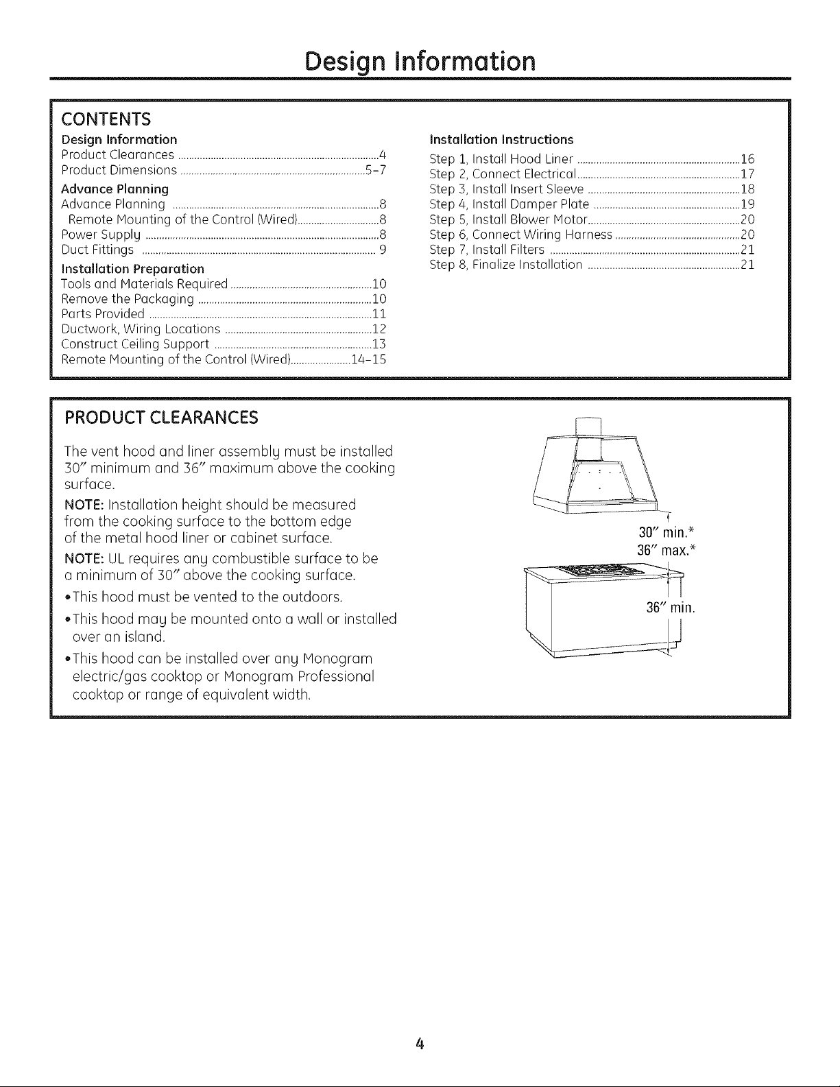
The vent hood and liner assemblg must be installed
50" minimum and 36" maximum above the cooking
surface.
NOTE: Installation height should be measured
from the cooking surface to the bottom edge
of the metal hood liner or cabinet surface.
NOTE: UL requires ang combustible surface to be
a minimum of 50" above the cooking surface.
•This hood must be vented to the outdoors.
Installation Instructions
Step 1, Install Hood Liner ............................................................16
Step 2, Connect Electrical ............................................................17
Step 3, Install Insert Sleeve ........................................................!8
Step 4, Install Damper Plate ......................................................19
Step 5, Install Blower Motor ........................................................20
Step 6, Connect Wiring Harness ..............................................20
Step 7, Install Filters ......................................................................21
Step 8, Finalize Installation ........................................................21
•This hood mag be mounted onto a wall or installed
over an island.
•This hood can be installed over ang Monogram
electric!gas cooktop or Monogram Professional
cooktop or range of equivalent width.
Page 5
Design Information
PRODUCT DIMENSIONS
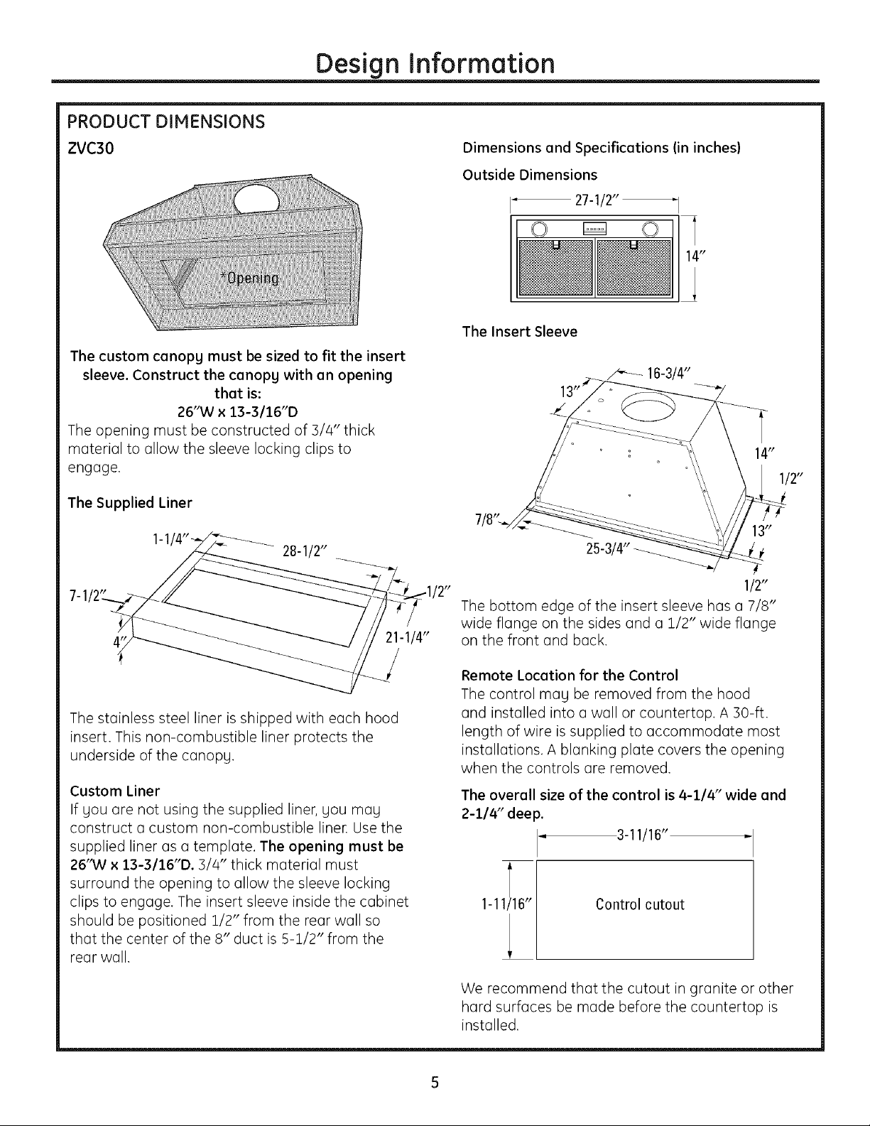
ZVC30 Dimensions and Specifications (in inches)
Outside Dimensions
27-1/2_
The Insert Sleeve
The custom canopg must be sized to fit the insert
sleeve. Construct the canopg with an opening
that is:
26"W x 13-3116"D
The opening must be constructed of 3/4" thick
material to allow the sleeve locking clips to
engage.
1/2"
The Supplied Liner
28-1/2"
21-1/4"
The stainless steel liner is shipped with each hood
insert. This non-combustible liner protects the
underside of the canopg,
Custom Liner
If gou are not using the supplied liner, gou mug
construct a custom non-combustible liner. Use the
supplied liner as a template. The opening must be
26'MI x 13-3116"D. 3/4" thick material must
surround the opening to allow the sleeve locking
clips to engage. The insert sleeve inside the cabinet
should be positioned 1/2" from the rear wall so
that the center of the 8" duct is 5-1/2" from the
rear wall.
251:,
'2"
The bottom edge of the insert sleeve has a 7/8"
wide flange on the sides and a 1/2" wide flange
on the front and back.
Remote Location for the Control
The control may be removed from the hood
and installed into a wall or countertop, A 30-ft.
length of wire is supplied to accommodate most
installations. A blanking plate covers the opening
when the controls are removed.
The overall size of the control is 4-114" wide and
2-1/4" deep.
4
1-11116"
3-11/16"
Control cutout
1/2"
We recommend that the cutout in granite or other
hard surfaces be made before the countertop is
installed.
Page 6
Design Information
PRODUCT DIMENSIONS
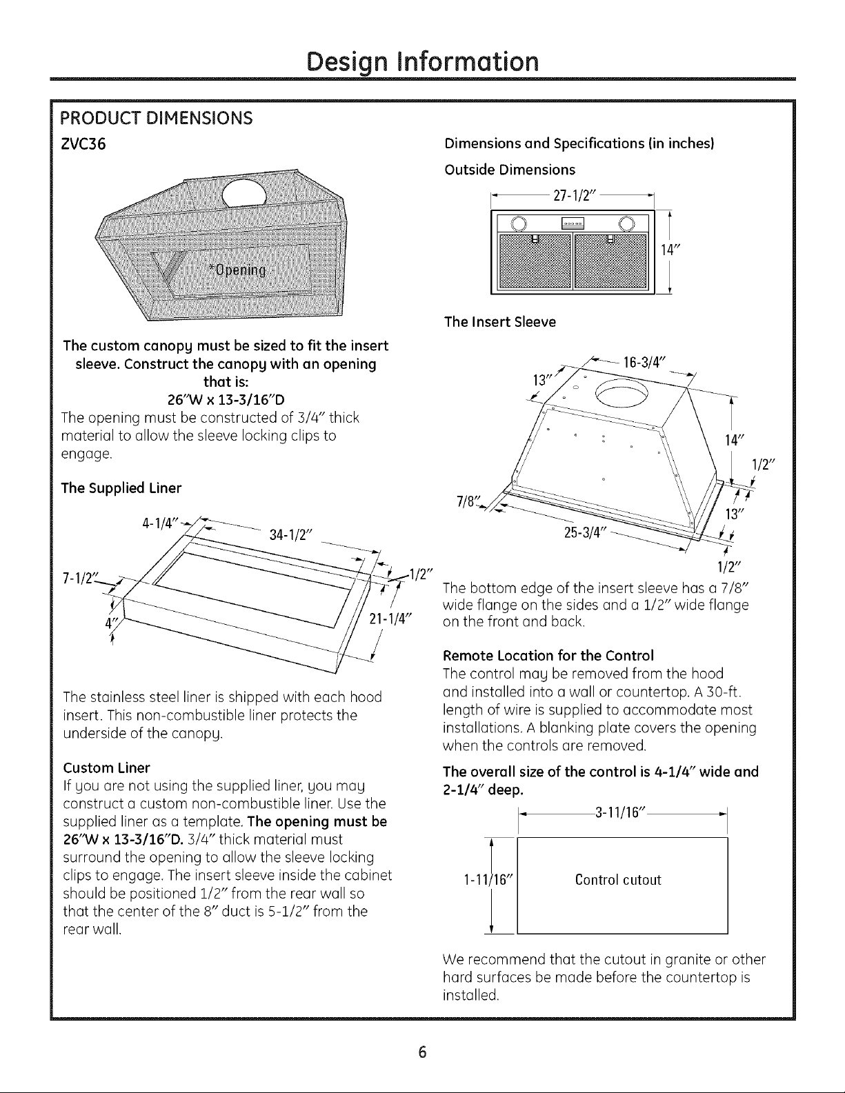
ZVC36 Dimensions and Specifications (in inches)
Outside Dimensions
27-1/2"
The Insert Sleeve
The custom canopg must be sized to fit the insert
sleeve. Construct the canopg with an opening
that is:
26"W x 13-3116"D
The opening must be constructed of 3/4" thick
material to allow the sleeve locking clips to
engage.
16-3/4"
14"
1/2"
The Supplied Liner
34-1/2"
The stainless steel liner is shipped with each hood
insert. This non-combustible liner protects the
underside of the canopg,
Custom Liner
If gou are not using the supplied liner, gou mag
construct a custom non-combustible liner. Use the
supplied liner as a template. The opening must be
26'MI x 13-3/16"D. 3/4" thick material must
surround the opening to allow the sleeve locking
clips to engage. The insert sleeve inside the cabinet
should be positioned 1/2" from the rear wall so
that the center of the 8" duct is 5-1/2" from the
rear wall.
1/2"
The bottom edge of the insert sleeve has a 7/8"
wide flange on the sides and a 1/2" wide flange
on the front and back.
Remote Location for the Control
The control mag be removed from the hood
and installed into a wall or countertop, A 30-ft.
length of wire is supplied to accommodate most
installations. A blanking plate covers the opening
when the controls are removed.
The overall size of the control is 4-1/4" wide and
2-1/4" deep.
3-11/16"
Control cutout
We recommend that the cutout in granite or other
hard surfaces be made before the countertop is
installed.
Page 7
PRODUCT DIMENSIONS
Design Information
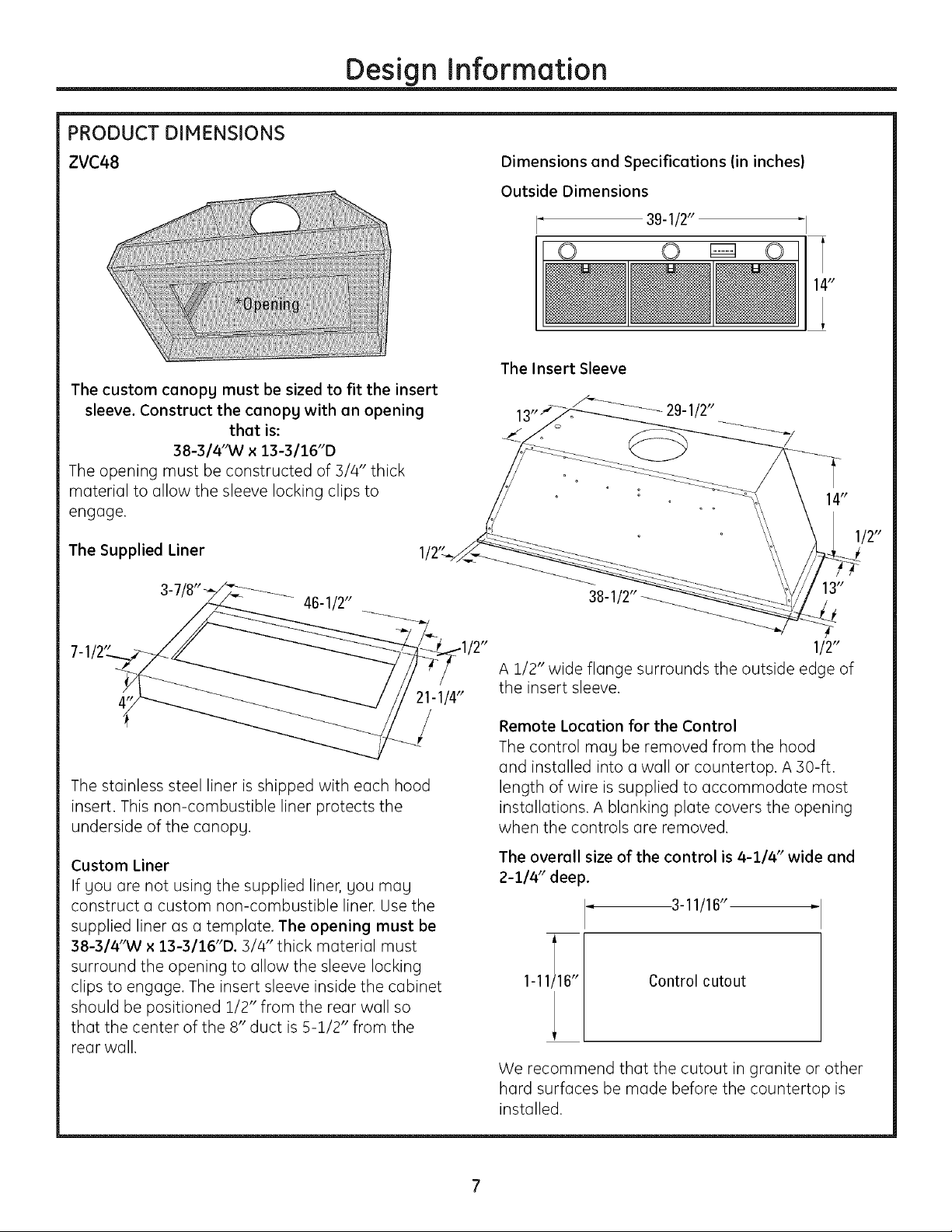
ZVC48
The custom canopy must be sized to fit the insert
sleeve. Construct the canopy with an opening
that is:
38-3/4"W x 13-3/16"D
The opening must be constructed of 3/4" thick
material to allow the sleeve locking clips to
engage.
The Supplied Liner
46-1/2"
Dimensions and Specifications (in inches)
Outside Dimensions
I" 39-1/2"
© © ©
The Insert Sleeve
29-1/2"
38-1
21-1/4"
_/
The stainless steel liner is shipped with each hood
insert. This non-combustible liner protects the
underside of the canopy,
Custom Liner
If you ore not using the supplied liner, you moy
construct a custom non-combustible liner. Use the
supplied liner as a template. The opening must be
38-3/4"W x 13-3/16"D. 3/4" thick moterial must
surroundtheopening to allowthe sleevelocking
dipstoengage. The insertsleeveinsidethe cabinet
should be positioned112"from the rearwallso
thatthe centerofthe 8"duct is5-1/2"from the
reor wall.
1/2"
A 1/2" wide flange surrounds the outside edge of
the insert sleeve.
Remote Location for the Control
The control may be removed from the hood
and installed into a wall or countertop. A 30-ft.
length of wire is supplied to accommodate most
installations. A blanking plate covers the opening
when the controls are removed.
The overall size of the control is 4-1/4" wide and
2-1/4" deep.
3-11/16"
Control cutout
1-11116"
We recommend thot the cutout in gronite or other
hard surfaces be made before the countertop is
installed.
Page 8
Advance Planning
ADVANCE PLANNING
Ductwork Planning
•This hood is equipped for 8" round ductwork.
• Determine the exact locution of the vent hood,
• Plan the route for venting exhaust to the outdoors,
This hood is not designed for a recirculating
venting operation,
• Use the shortest and straightest duct route
possible, For satisfactory performance, duct run
should not exceed 100 ft, equivalent length for any
duct configurations,
• Refer to "Duct Fittings" chart to compute the
maximum permissible length for duct runs to
the outdoors,
• Use rigid metal ductwork only,
• Install u wall or roof cap with damper at the
exterior opening. Order the cap and any transitions
needed in advance.
Wall and Ceiling Framing for Adequate Support
This vent hood is heavy and the cabinet structure
needs to support the weight of the loaded insert
sleeve. Adequate structural support must be
provided in all types of installations.
• Installation will be easier if the vent hood is
installed before the cooktop is installed,
Custom Cabinet Frame Planning
•The custom-built canopy should be sized to
accommodate the hood insert, and ducting
dimensions in the bottom of cabinet should be
26" W bg !3-3/!6" D for the 30" and 36" models
and 38-3/4" W by !3-3/!6" D for the 48" models.
Remote Mounting of the Control (Wired}
•The control can be remotely mounted on the wall
or the countertop.
• It is recommended that you use a professional
installer for the countertop cutout.
• It is recommended that the cutout in a granite
countertop or other hard surface be made before
the countertop is installed.
•The cutout needs to be made at least 6 inches
from the edges of the countertop.
• If mounting in the countertop above a drawer,
consideration must be given to the depth of the
control mounting assembly.
•A 30 ft. wire cord is provided. Careful consideration
must be given to the location of the remotely
mounted control.
• It is recommended that the a-wire cord be routed
through !" conduit between the insert sleeve and
the remote mounting location.
POWER SUPPLY
IMPORTANT - (Please read carefully)
WARNING:
FOR PERSONAL SAFETY,THIS APPLIANCE
MUST BE PROPERLYGROUNDED.
AVERTISSEMENT :POUR
DES RAISONS DE SECURITE,CET APPAREIL
DOlT ETRECORRECTEMENT HIS P,LA TERRE.
Remove house fuse or open circuit breaker before
beginning installation,
Do not use an extension cord or adapter plug with
this appliance, Follow National electrical codes or
prevailing local codes and ordinances.
Electrical Supply
This vent hood must be supplied with 120V, 60Hz,
and connected to an individual, properly grounded
branch circuit, and protected bg a 15 or 20 amp
circuit breaker or time delay fuse.
• Wiring must be 2 wire with ground.
• If the electrical supply does not meet the above
requirements, call a licensed electrician before
proceeding.
• Route house wiring as close to the installation
location as possible, in the ceiling or back wall,
• Connect the hood wiring to the house wiring in
accordance with local codes.
• House wiring must extend to 45" minimum from
bottom of cabinet in order to make connection to
hood wiring.
Grounding Instructions
The grounding conductor must be connected to
a grounded metal, permanent wiring system, or an
equipment-grounding terminal or lead on the hood.
connection of the equipment-grounding
WARNING: The improper
conductor can result in a risk of electric
shock. Check with a qualified electrician or service
representative if you are in doubt whether the
appliance is properly grounded.
Le mauvais branchement du fil de raise
AVERTISSEMENT :
la terre peut causer un choc @lectrique.
En cas de doute, consultez un @lectricien qualifi@
ou un technicien pour d6terminer si I'appareil est
la terre,
Page 9

Advance Planning
DUCT FITTINGS
Use this chart to compute
maximum permissible lengths for
duct runs to outdoors.
NOTE: Do not exceed maximum
permissible equivalent lengths!
Maximum duct length:
100 foot for 8" round duct
Flexible ducting:
If flexible metal ducting is used,
all the equivalent feet values in
the table should be doubled.
The flexible metal duct should
be straight and smooth and
extended as much as possible.
DO NOT use flexible plastic
ducting.
NOTE: Any home ventilation
system, such as a ventilation hood,
may interrupt the proper flow of
combustion air and exhaust
required by fireplaces, gas
furnaces, gas water heaters and
other naturally vented sgstems.
To minimize the chance of
interruption of such naturoffg
vented sgstems, follow the
heating equipment manufacturer's
guidelines and safety standards
such as those published by NFPA
and ASHRAE.
Equivalent Quantitg
Duct Piece Dimensions Length* Used
Round, i ft.
straight (per foot
length)
3-1/4" x 12" 1 ft.
3-1/4" x 24" (perfoot
straight length)
(_ 8" round
_ 8"to3-1/4"x12" 2ft.
_ 3-1/4" x 12" to 8" 2ft.
(_,,_,_ 8" to 3-1/4" x 10" 7 ft.
_,j_ 3-1/4" 12" to 8" Sft.
90° elbow 17 ft.
45° elbow 10 ft.
8" round
3-:1/4"x 10" 14 ft.
3-1/4" x 12" 15 ft.
90° elbow
3-1/4" x 12" 9 ft.
3-1/4" x 10" 8 ft.
45° elbow
3-1/4" x 10" 33 ft.
3-1/4" x 12" 36 ft.
90° flat elbow
8" to 3-1/4" x 10" 2 ft.
or 3-1/4" x 10" transition 2 ft.
3-1/4" x 10" to 8" 2ft.
round transition
8" to 3-1/4" x 12" 6 ft.
transition 90° elbow
3-1/4" x 10" to 8" 5ft.
X
round transition 90° elbow
Total
Equivalent
Length
*Actual length of straight duct plus
duct fitting equivalent. Equivalent
length of duct pieces are based
on actual tests conducted by GE
Evaluation Engineering and reflect
requirements for good venting
performance with any ventilation
hood.
wall cap
8" round
with damper 32 ft. with damper
3-1/4" x 12" wall cap
with damper 26 ft. with damper
<_ 8" roundroof cap 44 ft.
3-1/4" x 10" wall cap
w/damper 24 ft.
round roof vent
Total Duct Run.
Page 10

Installation Preparation
TOOLS AND MATERIALS REQUIRED
(NOT SUPPLIED)
Needle-nose pliers __
Aluminized
duct tape
Silicone
_ 1/4"pivoting
soo et
1" conduit (for remote
mounting only)
3/8" socket/
nut driver
Electric drill and
appropriate bits
Pencil and tape measure S _
"_ _ _;:_ _ Gloves
Knife L J 1
Step ladder
Plumb line Flashlight
Safety glasses
REMOVE THE PACKAGING
CAUTION: Wear gloves to protect
against sharp edges.
ATTENTION : Portez des gants pour
_viter les blessures caus_es par les tranchants.
CAUTION: LIFTTHE INSERT SLEEVE
OUT OF THE BOX BY GRASPING THE SIDES.
ATTENTION : SOULEVEZLE
HANCHON INTERIEUR DE LA BOITE EN SAISISSANT
SESCOTES.
Wire nuts
Phillips andflat blade Wire cutter/stripper Strain relief
screwdrivers
4. Unscrew the S nuts securing the damper vent
plate assemblg, and remove it from the insert
sleeve. Set the S nuts and the damper vent plate
assemblg aside, as SOUwill be re-installing it later
in the installation process.
8" ducting and
caps as needed
J
1. Open hood carton.
2. Remove the liner, foam and cardboard.
3. Remove the tape securing the filters to the insert
sleeve, lift the tabs and remove the filters.
5. Remove the screws attaching the insert sleeve to
the mounting board. Discard the screws.
6. Grasp the insert sleeve bg the outside edges, and
lift straight up and out of the carton.
NOTE: Do not lift the insert sleeve bg the blower
motor,
7, Remove and properlg discard the plastic wrapping,
8, Remove the parts box and other packaging,
10
Page 11

Installation Preparation
PARTS PROVIDED
Locate the parts packed with the hood.
CHECK INSTALLATION HARDWARE
components. Screws
shown actual size.
Count screws/
(not located in hardware
when you remove damper
Hood liner (packed in
separate carton)
5 nuts for damper plate
assembly
bag-you must save nuts
plate from inset hood
while unpacking parts)
screws for
hood liner
2 wing nuts
with lock
washers for
blower motor
REMOTE MOUNTING OF THE CONTROL (WIRED)
Blanking plate for
remote control
opening*
*NOTE:To be used
on custom hood
when controls are
remotely mounted.
8 wood
screws for
insert
sleeve
6 insert sleeve chassis
plugs, 1 (optional) house
wire hole plug, 2 rubber
grommets, 4 insert sleeve
washers
Control wall bracket
Control Control
mounting mounting
plate bracket
Insert sleeve
Filters
Blower motor
(Models ZVC30LSS and ZVC36LSS)
30 ft. of 4-wire cord
(straight-pinned)
with connector
NOTE: Not for
telecommunications
(telephone) network.
Dual blower motor
(Model ZVC48LSS)
2 mounting plate
screws 2wall
bracket
screws
Damper plate
11
Page 12

Wall Installation Preparation
DUCTWORK, WIRING LOCATIONS
Determine the exact location of the insert
sleeve. Mark the exact centerline location.
The ceiling structure must be capable of
supporting the weight of the insert sleeve
(appro×imatelg 100 pounds) and ang
inadvertent user contact loads, l
• Measure from the top of the cooking 16"abovepencil
surface to the bottom edge of the insert lineindicating
sleeve. Add insert sleeve installation height, bottomofhood
Mark that location.
Use a level to draw a straight horizontal
pencil line on the wall.
NOTE: House duct should drop to 11-1/2"
above bottom edge of insert sleeve.
Location of house duct is important
because it must align with vent of
damper plate assemblg.
Ceiling ducting:
If ductwork will vent straight up to the ceiling:
Use a level to draw a centerline straight up
to the ceiling.
On the ceiling, measure 5-1/2" from
the back wall to the centerline of an
8-!/2" hole.
Wall Ducting:
If ductwork will vent to the rear:
®Use a level to draw a centerline straight
up to the ceiling.
Measure at least 16" above the pencil line
that indicates the bottom installation height,
to the centerline of an 8-1/2" die. duct hole.
(Hole meg be elongated for duct elbow.)
30" Min.
36" Max,
installation
height
36" from
floor to
countertop
4" liner height
I
Side view
5-1/2" from
rear wall to
centerline
36" from
floor to
countertop
I I
Front view
HOUSE WIRING LOCATION:
Thejunction box is located inside the top left
side of the hood.
Wiring should enter the back wall at least
15" above the bottom of the insert sleeve,
and within 6" of the left side of the
centerline.
12
Page 13

Island Installation Preparation
CONSTRUCT CEILING SUPPORT (for Island Installation)
Plan the Location of the Hood and Ductwork
The ceiling structure must be capable of supporting the
weight of the insert sleeve (approximatelu !00 pounds)
and anu inadvertent user contact loads.
• Use a plumb bob to check the location, The
countertop/cooktop below the insert sleeve must be
centered with the insert sleeve.
The insert sleeve should extend beuond the front and
rear edge of the cooking appliance,
Ceiling
ducting
centerline
Front
Hood
t
30" Min,
Align with
center of
cooktop
, i _-_ Countertop
36" Max.
installation
i
i height j Cooktop
The insert sleeve in the ceiling must be centered left
to right over the cooktop,
30"'Min.
36" Max.
installation
height
I
Side view
I I
13
Page 14

InstallationPreparation
REMOTE MOUNTING OF THE CONTROL
(WIRED}
-- ILWARNING: Disconnectelectrical
power from unit before beginning remote control
installation. Failure to do so could result in personal
injurg or damage to the electrical controls.
AVERTISSEMENT : llfaut
d_brancher I'alimentation 61ectrique de I'appareil
avant de commencer I'installation de la commande
distance. IIfaut suivre cette directive pour @viter
des blessures ou endommager les commandes
61ectriques.
REMOTE LOCATION FOR CONTROL
The control can be removed from the hood and
installed in a backsplash or countertop.
• A cover plate is provided to cover the opening in
the hood when the control is removed.
• A 30-ft. length of 4-wire cord is supplied to
accommodate most installations. Because onlg
30-ft. of cord is provided, careful consideration
must be given to the location of the remotelg
mounted control.
NOTE: Not for telecommunication (telephone}
network.
• The cord must be routed through the holes in the
insert sleeve, and the rubber grommets put into
place around the cord.
NOTE: On the ZVC30 and ZVC36 models, the cord
needs to be routed through the holes in the insert
sleeve before the damper plate is installed.
• Route the cord through the conduit to reach the
installation location of the control.
3-11/16"
P
1-11116"
Control cutout
14
Page 15

InstallationPreparation
REMOTE MOUNTING OF THE CONTROL
(WIRED) {CONT.)
COUNTERTOP
Control
• , _"-"r"--..Connector
4-wire cordi-._" :
_ Mounting plate
Screws 4,-_ _--
Mounting bracket _ Apply silicone around
_cutout opening
I. Cut out opening in the countertop. Cutout
dimensions ore i-ii/16" x 3-ii/16".
2. Loosen the/4 thumbscrews ond remove the control
from the insert sleeve. Reploce the control with the
blanking plate provided.
3. Attoch the mounting plote to the bock of the
control with the 2 mounting plote screws.
4. Pull the a-wire cord through the opening in the
countertop, ond through the bock of the mounting
brocket.
NOTES: Use provided cable or cable designated bg
the National Electrical Code, NFPA/ANSI 70, or local
codes. Not for telecommunication (telephone}
network.
5. Connect the 4-wire cord to the jack of the
connector on the control.
6. Press the control firmlg into the mounting brocket
so that the clips engoge.
7. Applg silicone oround the cutout opening.
8. Insert the control into the cutout opening.
WALL MOUNT
Wall
bracket
I. Cut out opening into the woll surface. Cutout
dimensions are 1-11/16" x 3-11/16".
2. Loosen the/4 thumbscrews ond remove the
control from the insert sleeve. Replace the
control with the blonking plote provided.
3. Attach the mounting plote to the bock of the
control with the 2 mounting plote screws.
4. Pull the a-wire cord through the opening in
the wall, the woll brocket ond the back of the
mounting brocket.
NOTE: Use provided cable or cable designated bg
the National Electrical Code, NFPA/ANSI 70, or local
codes. Not for telecommunication (telephone}
network.
S. Connect the mounting brocket to the woll bracket
using the two wall brocket screws. Onlg start the
first 1-2 threads of the screws into the woll, os
gou wont to leove o gop between the two
brockets to occount for the woll thickness.
6. Raise the tabs on the mounting Tabs
brocket so the brocket will fit ,F_-------"_
through the woll opening.
7. Angle the mounting ond woll
brackets ond slide them through the woll cutout.
NOTE: Attach a string to the brackets, so gou can
retrieve them from behind the wall if dropped.
8. Flotten tobs on mounting bracket so theg ore
flush with the wall surfoce, ond tighten the woll
brocket screws to pull the woll brocket flonges
flush with the bockside surfoce of the woll.
9. Connect the a-wire cord to thejock of the
connector on the control.
I0. Press the control firmlg into the mounting
brocket so thot the clips engoge.
Mounting Control
bracket
¼ Jack
Screws,
__ord
plate
15
Page 16

Installation Instructions
[STEP I] INSTALL HOOD LINER
1. Frame the cutout opening to fit the linen
NOTE: The opening support must be 3/4" thick
wood to accept the liner installation screws.
3. Secure the liner to the cabinet with 6 screws
provided.
2. Slide the liner up Qnd into the opening until flush
with bottom edges.
16
Page 17

Installation Instructions
[STEP2] CONNECT ELECTRICAL
Verifg that power is turned off at the source.
WARNING: ,fhouse wiring is not
2-wirewitha ground wire,an electricianwillneed
toconvertexistingwiringto meet thesespecs.
When house wiringisaluminum, be sureto
use U.L approved anti-oxidantcompound
and aluminum-to-copper connectors.
AVERTISSEMENT:
Si le cablage de la maison n'est pas un cablage
5 deux ills avec un fil de terre, un @lectricien
doit convertir votre cablage existant 5 ces
caract@istiques techniques. Si le cablage de votre
maison est en aluminium, assurez-vous d'utiliser
un compos@ anti-oxgdant approuv6 et des
raccords aluminium _ cuivre.
I. Place insert sleeve on padded, get stable, surface
below cutout (can use flattened carton to pad
surface).
2. Remove the junction box cover
00000
00000
\
4. Connect white leads to branch circuit white lead.
5. Connect blackleadsto branch circuit blacklead.
6. Connect green/yellow leads to branch circuit green
lead.
7. Secure all connections with wire nuts on each
electrical connector
00000
\
\
Wires
3. Pull house wires through wall of insert sleeve and
attach the strain relief. Thread the house wire
through the junction box.
Cover
Screws
8. Carefully push wires intojunction box and replace
cover
9. Secure junction box cover with original screws.
17
Page 18

Installation Instructions
ISTEP31 INSTALL INSERT SLEEVE
1. Tuck the house wiring out of the wag.
2, Install the insert sleeve into the cutout opening of
custom cabinet frame.
÷
3. Push the insert sleeve straight up through the
cutout opening until the temporarg locking clips
engage. The locking clips are designed to hold the
insert sleeve in place until it is secured with screws.
NOTE: The locking clips are not designed to support
all of the weight of the insert sleeve. Do not leave the
insert sleeve unattended until screws have been
inserted.
ape
4. Align 8" duct to exhaust opening of insert sleeve
and seal with aluminum tape.
NOTE: House duct should drop to 11-1/2" above
bottom edge of insert sleeve or the bottom of the
3/4" cabinet base.
5. Tape the 4 washers in place over the outside
of the 4 front and back holes of the insert sleeve.
The washers are designed to be located between
the insert sleeve and the 3/4" cabinet surface.
6. Press the sleeve up firmlg and secure with the
8 screws provided. The insert sleeve should be
flush with the liner and have no visible gaps.
NOTE: It is IHPORTANT to install front mounting
screw. The front screw hole is difficult to see and
mag require gou to place gour head into the cutout
opening to locate.
18
Page 19

Installation Instructions
[STEP4] INSTALL DAMPER PLATE
1. Pick up damper plate assemblg and rotate so that °
vent side is up and bracket is located on left as gou 3. Secure damper plate assemblg bg placing nuts
stand facing hood. on bolts and tightening with socket or wrench.
2. Insert damper plate assemblg into insert sleeve
and carefullg align with 8" house duct.
19
Page 20

Installation Instructions
ISTEPslINSTALL BLOWER MOTOR
iioooooii
1. Pick up blower motor and rotate so tabs align
with damper plate bracket.
2. Insert blower motor into insert sleeve through
cutout opening of custom cabinet frame.
ISTEP6 1CONNECTWIRING HARNESS
3. Place blower motor on damper plate assemblg
bg sliding blower motor tabs into slots of damper
plate assemblg.
00000
4. While holding blower motor in place, lift right side
so that blower motor bolt holes align with bolts
protruding from damper plate assemblg and
secure with lock washers and wing nuts (hand
tighten).
NOTE:OnZVC48,there arethree routing clips andtwo wiring harnessesto connect.
Wiring
harness o ooo o
®
1. Locate both ends of wiring harness. 3. CarefullL
2. Connect wiring harness bg inserting male into
female opening.
through two clips attached to blower plate
assemblg.
route wiring harness and ground wire
2O
Brackets
Page 21

Installation Instructions
ISTEP7] INSTALLFILTERS
1.Remove protective film from the filters.
Clip
2. Tip the filter into the back tab slots and lift up.
While maintaining slight backward pressure
on filter, open clip and press into place with
two hands.
[STEP 8] FINALIZE INSTALLATION
1.Checkto be sure all tape and packaging
materials have been removed.
2. Refer to Owner's Manual for operating
instructions.
3. To remove, support filter with one hand while
pulling filter clip down with the othen
21
Page 22

Notes
22
Page 23

Notes
23
Page 24

Printed in Italg
Note: While performing installations described in this book,
safety glasses or goggles should be worn.
For Monogram ® local service in your area, call
1.800.444.1845.
Note: Product improvement is a continuing endeavor at
General Electric. Therefore, materials, appearance and
specifications are subject to change without notice.
Monogram:
GEConsumer&hldustrial
GEAppliances
GeneralElectricCompany
Louisville,KY40225
ge com
@2006GECompany
 Loading...