

Page 1
ZVB36SN/BN
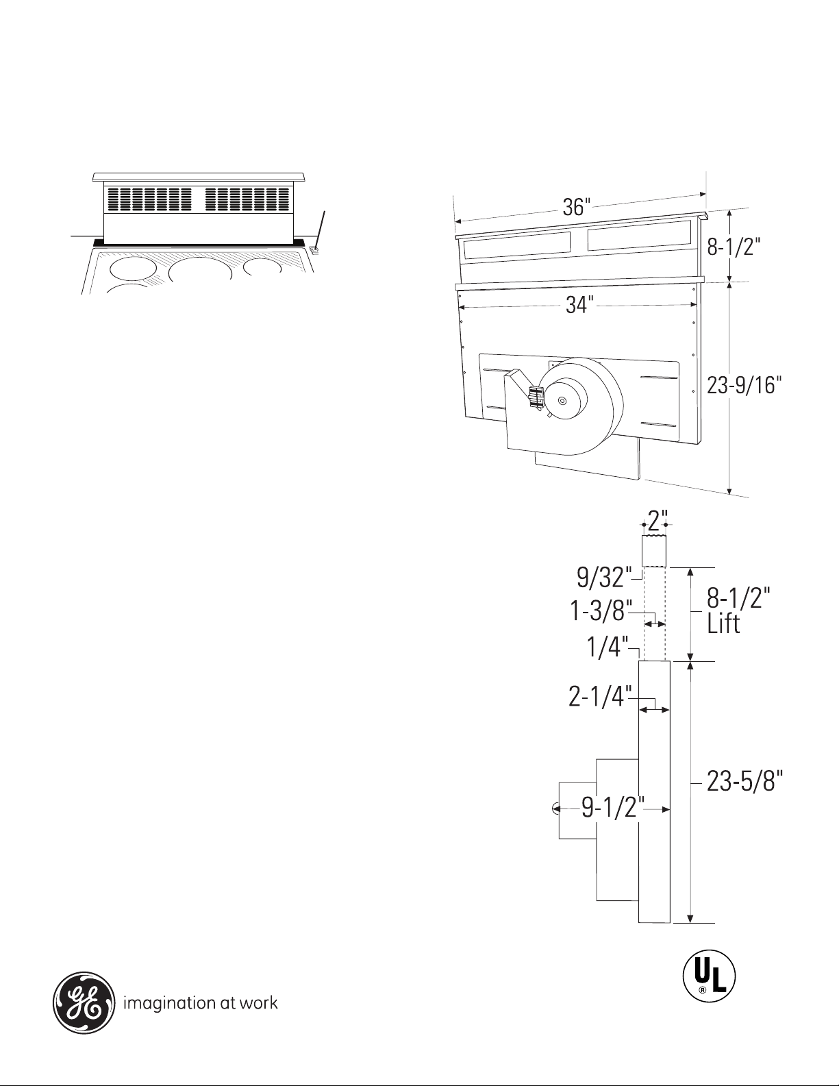
GE Monogram® 36" Telescopic Downdraft Vents
Dimensions and Installation Information (in inches)
Separate Raise/
Lower Switch
All 36" models are equipped with a separate raise/lower
switch. The switch must be installed in a separate location
outside of the vent and cooktop cutout.
Countertop Requirements
Countertops must have a deep at surface to accommodate
the cooktop and the vent. Countertops with a rolled edge and
backsplash may not provide the at surface area required.
Base Cabinet Requirements
The base cabinet must be deep enough to accommodate the
minimum clearance to the front edge of the countertop, the
cooktop burner box and the vent.
Downdraft Vent and Cooktop Cutout
The installation of these downdraft vents with any Monogram
cooktop requires careful consideration. For accurate planning,
review the individual dimension drawings for the combined vent
and Monogram cooktop installation.
Before you begin you must:
1. Review countertop dimension illustrations to be sure you will
have enough at countertop surface depth.
2. Check to be sure that the total countertop depth required
(including minimum cutout to front edge depth) allows enough
space for a backsplash.
3. Review the cabinet illustration. Check to be sure that the
interior cabinet depth will house the cooktop burner box, the
vent and the cutout clearance from the front.
4. When countertop and cabinet depth present a problem, review
Creative Solutions.
5. Carefully review the installation instructions packed with
product or available online at www.monogram.com.
With careful planning you can achieve a custom look with
minimal adjustments.
For answers to your Monogram,® GE Profile™ or
GE® appliance questions, visit our website at
ge.com or call GE Answer Center® service,
800.626.2000.
Specification Created 11/08
Listed by
Underwriters
Laboratories
130676
Page 2
ZVB36SN/BN
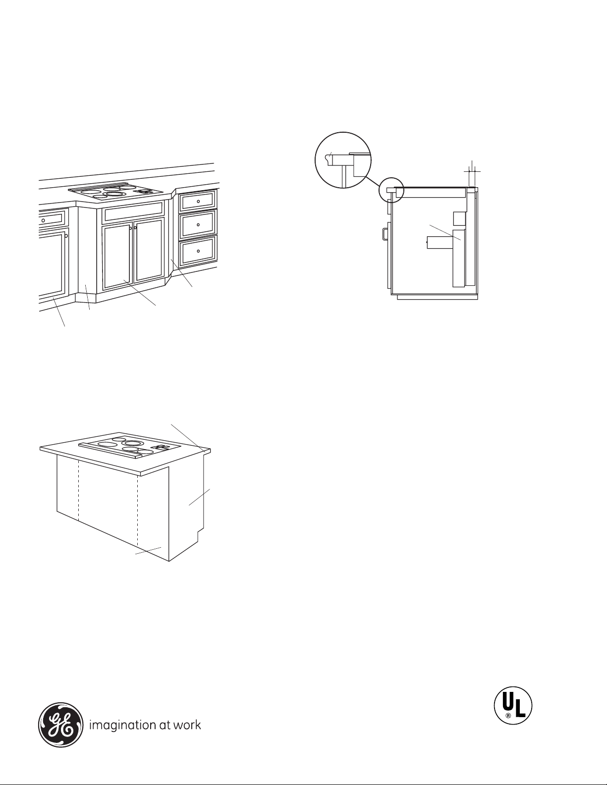
Base Cabinet
Filler Panel
Base Sink
Filler Panel
Maintain Cutout Clearances
to Front Edge as Specified
Cover Panel
Base Sink
End
Panel
Countertop Overhang per Cooktop
Clearances Must be Maintained
DOWNDRAFT
VENT
1-7/8"
Trim
Add a Bullnose
Trim or Decorative
Molding to
Increase
Countertop
Depth and to
Maintain
Required
Clearance From
Front Edge
GE Monogram® 36" Telescopic Downdraft Vents
Dimensions and Installation Information (in inches)
Creative Solutions
Decorative trim
When the cutout to front edge of the countertop
Against-the-wall installation
Move the base cabinet forward, 3" to 5". Filler panels or
complimentary moldings can be added to the exposed
cabinet sides.
requirement is more than 2", add a bullnose trim to the
front edge of the countertop. The additional trim allows
the cooktop to be moved forward, providing additional
countertop depth and interior cabinet space.
Optional Accessories
JXRB67 Accessory for indoor remote location of the blower/
motor assembly. Use this kit when the blower and motor
assembly will be located outside of the cabinet, such as
below the cabinet oor. The assembly will t between 16"
oor joists.
JXBC67 Outdoor cover accessory for remote installation of
the blower/motor assembly on an outside wall.
Island or peninsula installation
Use an extra-deep countertop. The countertop overhang at the
front can be adjusted to meet setback to cutout requirements.
For answers to your Monogram,® GE Profile™ or
GE® appliance questions, visit our website at
ge.com or call GE Answer Center® service,
800.626.2000.
Ductwork
Prepare the ductwork to vent to the outdoors.
• Plan the shortest and straightest route for venting exhaust
to the outdoors.
• The maximum permissible length for the duct run is 150 feet.
• Use metal ductwork only.
• The downdraft blower system is designed to use 3-1/4" x
10" duct. It can be transitioned to 6" round.
• Install a wall cap or roof cap with damper at the exterior
opening. Order the wall cap and any transition needed in
advance.
Listed by
Underwriters
Laboratories
Specification Created 11/08
130676
Page 3

ZVB36SN/BN
34" for 36" Models
28-1/2" for 30" Models
29-1/2"
Electrical
Outlet
12" Above
Cabinet Floor
Do Not Locate Gas or Electrical
Connections Within Shaded Area
GE Monogram® 36" Telescopic Downdraft Vents
Dimensions and Installation Information (in inches)
Electrical and Gas Locations
Plan the placement of the electrical outlet and gas (if used)
carefully. Gas or electrical outlets cannot be located on the
back wall of the cabinet because they may interfere with the
downdraft plenum.
• Install a standard electrical outlet within reach of the
vent’s two-foot-long power cord. Locate the outlet inside
the cabinet on the right side wall.
• If the vent is installed in combination with a Monogram®
gas cooktop, it may operate from the same 120V standard
duplex outlet.
• If the vent is installed in combination with a Monogram
electric cooktop, the vent must operate from a separate
120V outlet.
Venting Options
The downdraft vent is shipped with the discharge outlet
pointing straight down and can be changed to a left- or
right-side discharge. For even more exibility, the entire
blower and mounting plate can be adjusted 3-1/2" to the
left or right sides.
For answers to your Monogram,® GE Profile™ or
GE® appliance questions, visit our website at
ge.com or call GE Answer Center® service,
800.626.2000.
Specification Created 11/08
Listed by
Underwriters
Laboratories
130676
Page 4

ZVB36SN/BN
GE Monogram® 36" Telescopic Downdraft Vents
Features and Benets
• Raises To 8-1/2” Over Cooktop Surface When
You Cook, Then Retracts When Not in Use
• 500-CFM Performance Helps Keep Your Kitchen
Free of Fumes and Excess Heat
• Remote-Mounted Control Provides
Design Flexibility
• Variable-Speed Blower with Electronic Controls
Complements Most Monogram Cooktops
• Removable Grease Filters Trap Airborne
Grease Particles
• Optional Remote Blower Capabilities
• Stainless Steel Vent Body Oers a Smooth and
Polished Appearance
• Model ZVB36SNSS - Stainless steel (shown)
• Model ZVB36BNBB - Black on black
For answers to your Monogram,® GE Profile™ or
GE® appliance questions, visit our website at
ge.com or call GE Answer Center® service,
800.626.2000.
Specification Created 11/08
130676
 Loading...