

Page 1
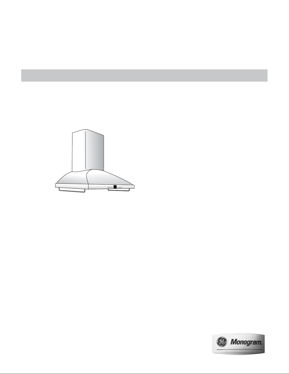
Installation
Instructions
If you have questions, call 800.GE.CARES or visit our website at: www.monogram.com
ZV950
36" Stainless Steel
Vent Hood
Page 2
Safety Information
BEFORE YOU BEGIN
Read these instructions completely and carefully.
• IMPORTANT– Save these instructions
for local inspector’s use.
• IMPORTANT – Observe all governing codes
and ordinances.
• Note to Installer – Be sure to leave these
instructions with the Consumer.
•
Note to Consumer – Keep these instructions
with your Owner’s Manual for future reference.
• Skill Level – Installation of this appliance requires basic
mechanical and electrical skills.
• Completion time – 1 to 3 hours.
• Proper installation is the responsibility of the installer.
Product failure due to improper installation is not covered under the Warranty.
For Monogram local service in your area,
1.800.444.1845.
For Monogram service in Canada, call
1.800.561.3344.
For Monogram Parts and Accessories, call
1.800.626.2002.
CAUTION:
Due to the weight and size of these vent hoods, and
to reduce the risk of personal injury or damage to the
product, TWO PEOPLE ARE REQUIRED FOR PROPER
INSTALLATION.
PRUDENCE
À cause du poids et de la taille de ces hottes, et pour
réduire le risque de blessures et de dommages, IL FAUT
DEUX PERSONNES POUR FAIRE L’INSTALLATION CORRECTEMENT.
WARNING:
To reduce the risk of re or electrical shock, do not use
this range hood with any external solid-state speed control device. Any such alteration from original
factory wiring could result in damage to the unit
and/or create an electrical safety hazard.
AVERTISSEMENT
Pour réduire le risque d’incendie ou de choc électrique,
il ne faut pas utiliser cette hotte avec un régulateur
de vitesse électronique externe. Toute modication
de ce type du branchement d’usine peut endommager
l’appareil ou créer un risque de choc électrique.
WARNING: TO REDUCE THE RISK OF
FIRE, ELECTRICAL SHOCK OR INJURY TO PERSONS,
OBSERVE THE FOLLOWING:
A. Use this unit only in the manner intended by the
manufacturer. If you have any questions, contact the
manufacturer.
B. Before servicing or cleaning unit, switch
power o at the service panel and lock service
panel to prevent power from being switched on
accidentally. If the service panel cannot be locked,
fasten a tag or prominent warning label to the panel.
AVERTISSEMENT
POUR RÉDUIRE LE RISQUE D’INCENDIE, DE CHOC
ÉLECTRIQUE OU DE BLESSURES, IL FAUT OBSERVER LES
RÈGLES SUIVANTES :
A. Utiliser cet appareil uniquement de la manière
prévue par le fabricant. En cas de question,
consulter le fabricant.
B. Avant toute intervention ou nettoyage, couper
l’alimentation électrique au disjoncteur et verrouiller
le panneau du disjoncteur pour éviter la mise
sous tension accidentelle. S’il n’est pas possible de
verrouiller le panneau du disjoncteur, attacher un
placard ou une étiquette très visible au panneau.
• For general ventilating use only. Do not use to
exhaust hazardous or explosive materials or vapors.
• Structural framing, installation work and electrical
wiring must be done by qualied person(s) in
accordance with all applicable codes and standards
including re-rated construction.
• Sucient air is needed for proper combustion and
exhausting of gases through the ue (chimney) of fuel
burning equipment to prevent back drafting. Follow
the heating equipment manufacturer’s guidelines
and safety standards such as those published by the
National Fire Protection Association (NFPA), and the
American Society for Heating, Refrigeration and Air
Conditioning Engineers (ASHRAE), and the local code
authorities.
• Local codes vary. Installation electrical connections
and grounding must comply with applicable codes.
In the absence of local codes, the vent should be
installed in accordance with National Electrical Code
ANSI/NFPA 70-1990 or latest edition.
CAUTION: To reduce risk of re and to
properly exhaust air, be sure to duct air outside–Do not
vent exhaust air into spaces within walls or ceilings or
into attics, crawl spaces or garages.
TO REDUCE THE RISK OF FIRE, USE ONLY METAL DUCTWORK.
PRUDENCE–Il faut prendre soin d’installer
un conduit vers l’extérieur pour réduire le risque
d’incendie et pouvoir évacuer l’air correctement.
Il ne faut pas évacuer l’air dans l’espace entre les parois
d’un mur, un plafond ou un grenier, un espace sanitaire
ou un garage.
2
Page 3
Design Information
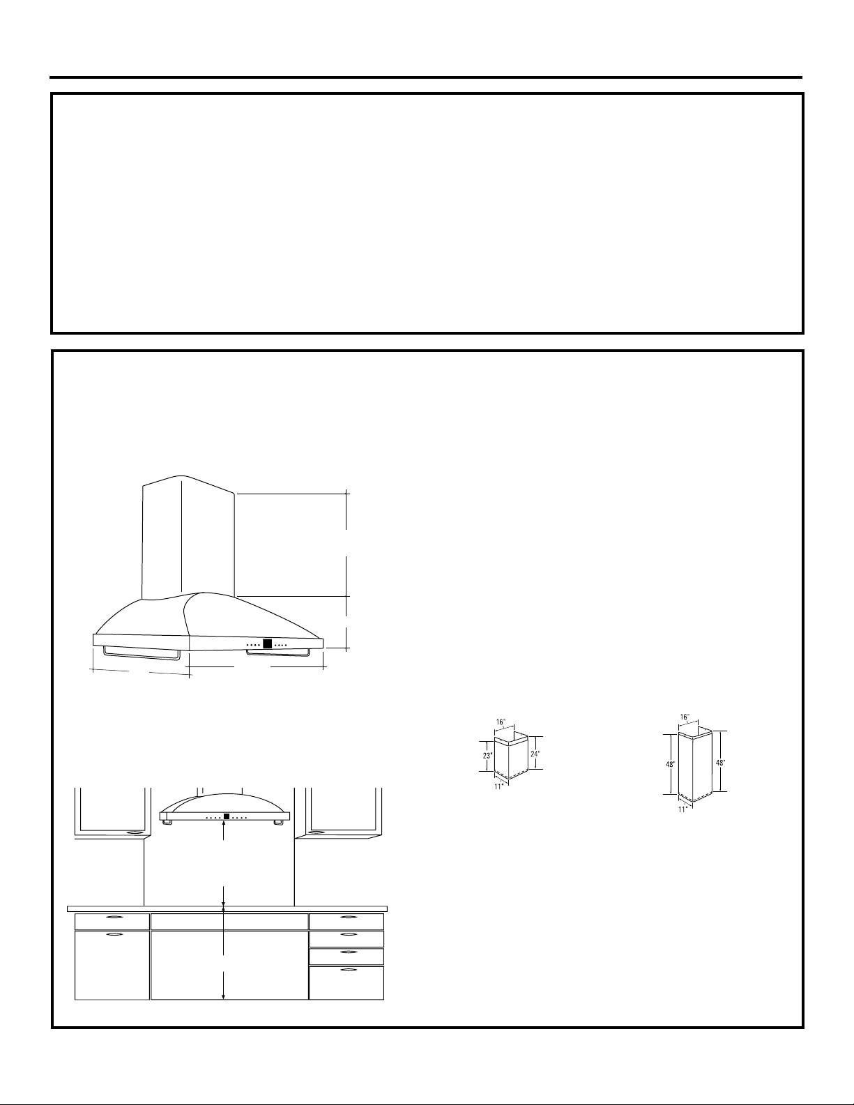
10"
*Height
to Ceiling
35-5/8"
25"
Installation
Height Depending
on Ceiling Height
36" Min.
CONTENTS
Design Information
Product Dimensions and Clearances .......................................3–4
Optional Accessories ............................................................................4
Installation Preparation
Advance Planning,
Ductwork, Framing ..............................................................................5
Power Supply ............................................................................................5
Duct Fittings ..............................................................................................6
Tools and Materials Required ...........................................................7
Remove the Packaging ........................................................................7
Check Installation Hardware .............................................................8
PRODUCT DIMENSIONS AND CLEARANCES
36" Vent Hood Installation Combinations
This Stainless Steel Hood can be installed over any Monogram cooktop, including the Professional 36" rangetop and
30" or 36" range.
Ductwork, Wiring Locations ..............................................................8
Installation Instructions
Step 1, Install Framing for Hood Support ....................................9
Step 2, Install Mounting Brackets ...................................................9
Step 3, Install Duct Bracket ............................................................. 10
Step 4, Install the Hood ..................................................................... 10
Step 5, Connect Ductwork ............................................................... 11
Step 6, Connect Electrical ................................................................ 11
Step 7, Install Duct Covers ............................................................... 11
Step 8, Install Filters ............................................................................ 12
Step 9, Finalize Installation .............................................................. 12
Cooking surface to bottom of hood should be:
• 25-1/2" max. for 8 ft. ceiling height.
• 25-1/2" to 30" for 9 ft. ceiling height.
• 30" min. for 10 ft. ceiling height.
Plan the installation height carefully to avoid unsightly
gaps above the hood.
*The supplied duct cover ts 8 ft. to 10 ft . ceilings.
The vent hood must be installed 24" min. and 30" max.
above the cooking surface. The hood installation height,
from the cooking surface to the bottom of the hood, depends upon ceiling height.
This hood must be installed 30" min. above a Monogram
Professional Cooktop or Range. Ceiling height for this installation combination must be at least 8'5" high.
Note: The supplied 2-piece duct cover is adjustable to t 8
ft. to 10 ft. ceilings. For ceiling heights greater than
10 ft. and up to 14 ft., order ZX14SDSS stainless steel duct
cover accessory.
ZV950SDSS Duct Cover
Dimensions
ZX14SDSS Duct Cover
Dimensions
3
Page 4
Design Information
PRODUCT DIMENSIONS AND CLEARANCES (cont.)
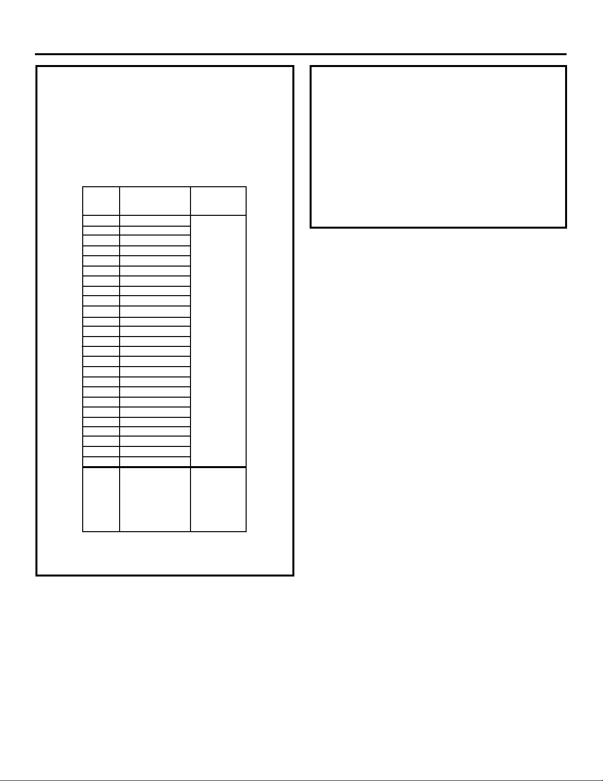
Using Duct Cover Accessories
A Duct Cover Accessory may be required for your hood
installation height. Use this chart to determine installation height and accessory for your ceiling height.
ZV950SDSS Installation Heights
Actual
Ceiling
Height
7' 11"
8' 0"
8' 1"
8' 2"
8' 3"
8' 4"
8' 5"
8' 6"
8' 7"
8' 8"
8' 9"
8' 10"
8' 11"
9' 0"
9' 1"
9' 2'
9' 3'
9' 4"
9' 5"
9' 6"
9' 7"
9' 8"
9' 9"
9' 10"
9' 11"
10' 0"
* Possible Hood
Installation Height
24-1/2"
25-1/2"
25-1/2" to 26-1/2"
25-1/2" to 27-1/2"
25-1/2" to 28-1/2"
25-1/2" to 29-1/2"
25-1/2" to 30"
25-1/2" to 30"
25-1/2" to 30"
25-1/2" to 30"
25-1/2" to 30"
25-1/2" to 30"
25-1/2" to 30"
25-1/2" to 30"
26-1/2" to 30"
26-1/2" to 30"
26-1/2" to 30"
26-1/2" to 30"
26-1/2" to 30"
30" min.
30" min.
30" min.
30" min.
30" min.
30" min.
Duct Cover
SUPPLIED
OPTIONAL ACCESSORIES
ZX14SDSS, optional stainless steel duct cover is available
for ceiling heights greater than 10 ft. and up to 14 ft.
Order the optional duct cover at the same time as the
vent hood and have on site before installation. This kit
contains hardware required for installation. This kit contains installation hardware.
Note: Duct covers must be installed as shown in this
book. Do not “build-in” the duct cover. If service is
required, the duct cover must be removed to access
hood components.
30" min.
14' 0"
* Based on 36" countertop height.
The serial plate is located behind the removable lters.
ZX14SDSS
4
Page 5

Installation Preparation
ADVANCE PLANNING
Ductwork Planning
• Determine the exact location of the vent hood.
• Plan the route for venting exhaust to the outdoors.
• Use the shortest and straightest duct route possible. For
satisfactory performance, duct run should not exceed
100 equivalent length for any duct congurations.
• Refer to “Duct Fittings” chart to compute the maximum
permissible length for duct runs to the outdoors.
CAUTION: To reduce risk of re and to properly
exhaust air, be sure to duct air outside–Do not vent exhaust air into spaces within walls or ceilings or into attics,
crawl spaces or garages.
PRUDENCE – Il faut prendre soin d’installer un
conduit vers l’extérieur pour réduire le risque d’incendie et
pouvoir évacuer l’air correctement. Il ne faut pas évacuer
l’air dans l’espace entre les parois d’un mur, un plafond ou
un grenier, un espace sanitaire ou un garage.
• Use metal ductwork. These hoods must use 8" round
duct. It can transition to 3-1/4" x 12", reducing the maximum equivalent duct length to 75 feet.
• Install a wall cap with damper or roof cap at the exterior
opening. Order the wall or roof cap and any transition
needed in advance.
Wall Framing for Adequate Support
• This vent hood is heavy. Adequate structural support
must be provided. The hood must be secured to vertical
studs in the wall, or to a horizontal support. See page 9.
• We strongly recommend that the vent hood with duct
cover be on site before nal framing and wall nishing.
This will also help to accurately locate the ductwork and
electrical service.
POWER SUPPLY
IMPORTANT – (Please read carefully)
WARNING:
FOR PERSONAL SAFETY, THIS APPLIANCE MUST BE PROPERLY GROUNDED.
AVERTISSEMENT
POUR DES RAISONS DE SÉCURITÉ, CET APPAREIL DOIT ÊTRE
CORRECTEMENT MIS À LA TERRE.
Remove house fuse or open circuit breaker before
beginning installation.
Do not use an extension cord or adapter plug with this appliance. Follow National Electrical Code or prevailing local
codes and ordinances.
Electrical supply
This vent hood must be supplied with 120V, 60Hz, and connected to an individual, properly grounded branch circuit,
and protected by a 15 or 20 amp circuit breaker or time
delay fuse.
• Wiring must be 2 wire with ground.
• If the electrical supply does not meet the above requirements, call a licensed electrician before proceeding.
• Route house wiring as close to the installation location
as possible in the ceiling or sot. Wiring should enter at
least 4" above the bracket on the right side.
• Connect the wiring to the house wiring in accordance
with local codes.
Grounding instructions
The grounding conductor must be connected to a ground
metal, permanent wiring system, or an equipmentgrounding terminal or lead on the hood.
WARNING: The improper connection of the
equipment-grounding conductor can result in a risk of
electric shock. Check with a qualied electrician or service
representative if you are in doubt whether the appliance is
properly grounded.
AVERTISSEMENT
Le mauvais branchement du l de mise à la terre peut
causer un choc électrique. En cas de doute, consulter un
électricien qualié ou un technicien pour déterminer si
l’appareil est à la terre.
5
Page 6
Installation Preparation
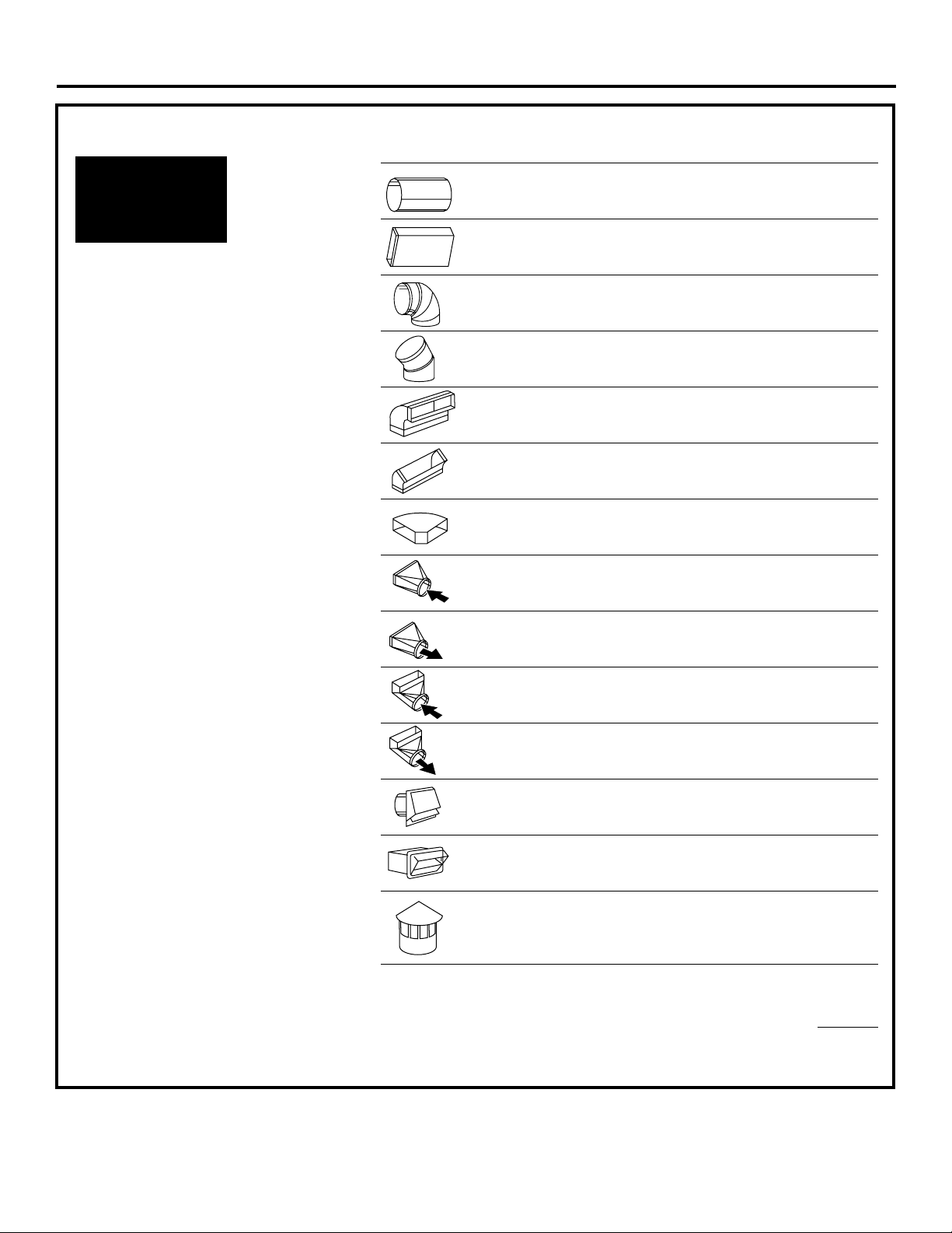
DUCT FITTINGS
This Hood Must
Use 8" Round Duct.
It Can Transition to
3-1/4" x 12" Duct.
Use this chart to compute maximum
permissible lengths for duct runs to
outdoors.
Note: Do not exceed maximum permissible
equivalent lengths!
Maximum duct length:
100 ft. for range hoods.
Flexible ducting:
If exible metal ducting is used, all
the equivalent feet values in the table
should be doubled. The exible metal
duct should be straight and smooth and
extended as much as possible.
Equivalent Quantity Equivalent
Total
Duct Piece Dimensions Length* Used Length
Round, 1 ft.
straight length
90° elbow 17 ft.
45° elbow 10 ft.
3-1/4" x 12"
90° elbow 43 ft.
3-1/4" x 12"
45° elbow 26 ft.
3-1/4" x 12"
90° at elbow 102 ft.
straight (per foot
length)
1 ft.
3-1/4" x 12" (per foot
)
Do NOT use exible plastic ducting.
Note: Any home ventilation system, such as a
ventilation hood, may interrupt the proper ow
of combustion air and exhaust required by replaces, gas furnaces, gas water heaters and other
naturally vented systems. To minimize the chance
of interruption of such naturally vented systems,
follow the heating equipment manufacturer’s
guidelines and safety standards such as those
published by NFPA and ASHRAE.
8" round to
3-1/4" x 12" transition 2 ft.
3-1/4" x 12"
to 8" round transition 5 ft.
8" round
to 3-1/4" x 12"
transition 90° elbow 6 ft
3-1/4" x 12" to 8"
round transition 90° elbow 13 ft.
wall cap
with damper 32 ft.
3-1/4" x 12" wall cap
with damper 75 ft.
Round
roof cap 44 ft.
* Actual length of straight duct plus duct tting equivalent. Equiva-
lent length of duct pieces are based on actual tests conducted
by GE Evaluation Engineering and reect requirements for good
venting performance with any ventilation hood.
Round
.
Total Duct Run
6
Page 7
Installation Preparation
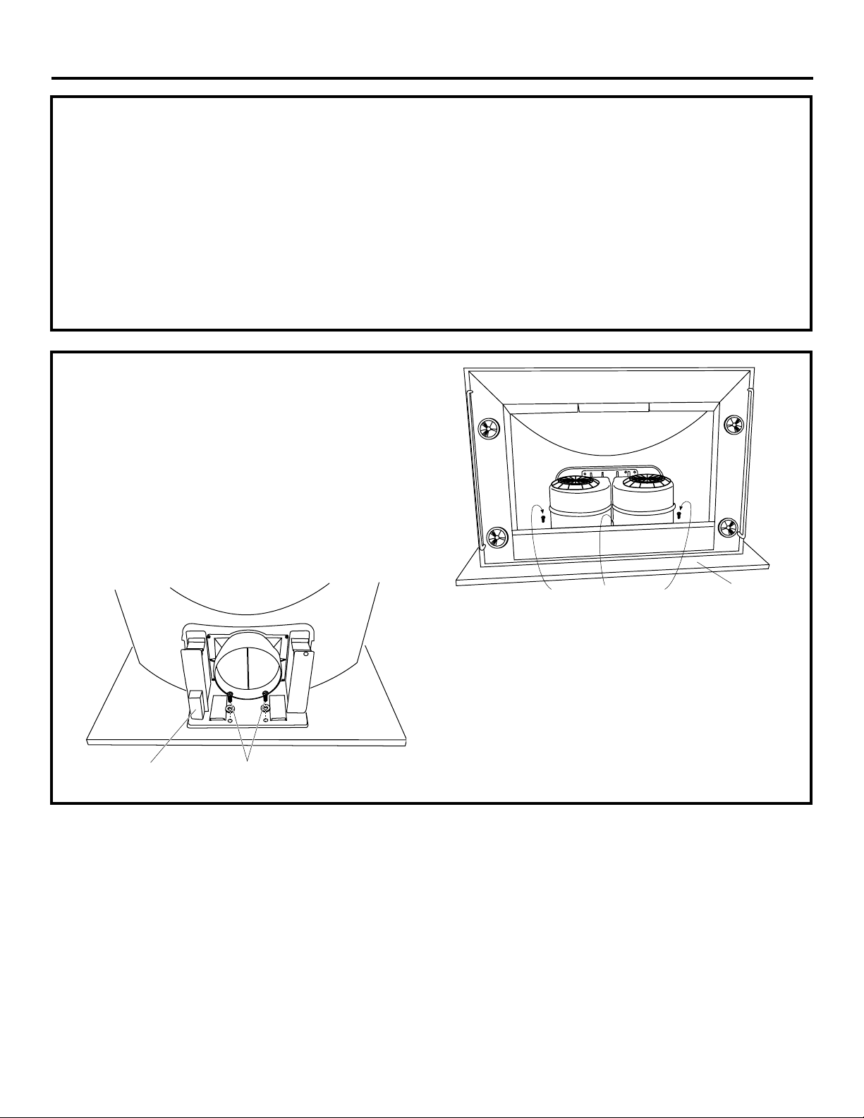
Top Shipping Screws
Junction
Box
Shipping Board
Remove Bottom Shipping
Screws and Shipping Bracket
TOOLS AND MATERIALS REQUIRED
(NOT SUPPLIED)
• Tape measure
• Knife
• Spirit level
• Wire cutter/stripper
• Wire nuts
• Electric drill with 1/8" and 3/8" bits
• Phillips and at blade screwdrivers
• Hammer
• Pliers
• Safety glasses
REMOVE THE PACKAGING
The hood is shipped secured to a shipping board with (4)
screws. Remove the 4 screws. Two screws are located at
the top of the hood. Two are located at the bottom of the
hood behind the grease lters.
A shipping bracket, which supports the blower, must also
be removed. It is secured with two screws. All screw impressions are Phillips.
• Remove all packaging, the duct covers, and accessories.
• Lift the hood out of the carton.
• Remove and properly discard all plastic wrapping.
• Duct tape
• Tape to mount template
• Gloves to protect against sharp edges
• 120V 60Hz. 15 or 20 Amp, 2 wire with ground.
Properly grounded branch circuit.
• Strain relief for junction cover.
• 8" round metal duct, length to suit installation.
Top Of Hood
• Remove junction box cover.
• Install strain relief into junction box cover.
7
Page 8
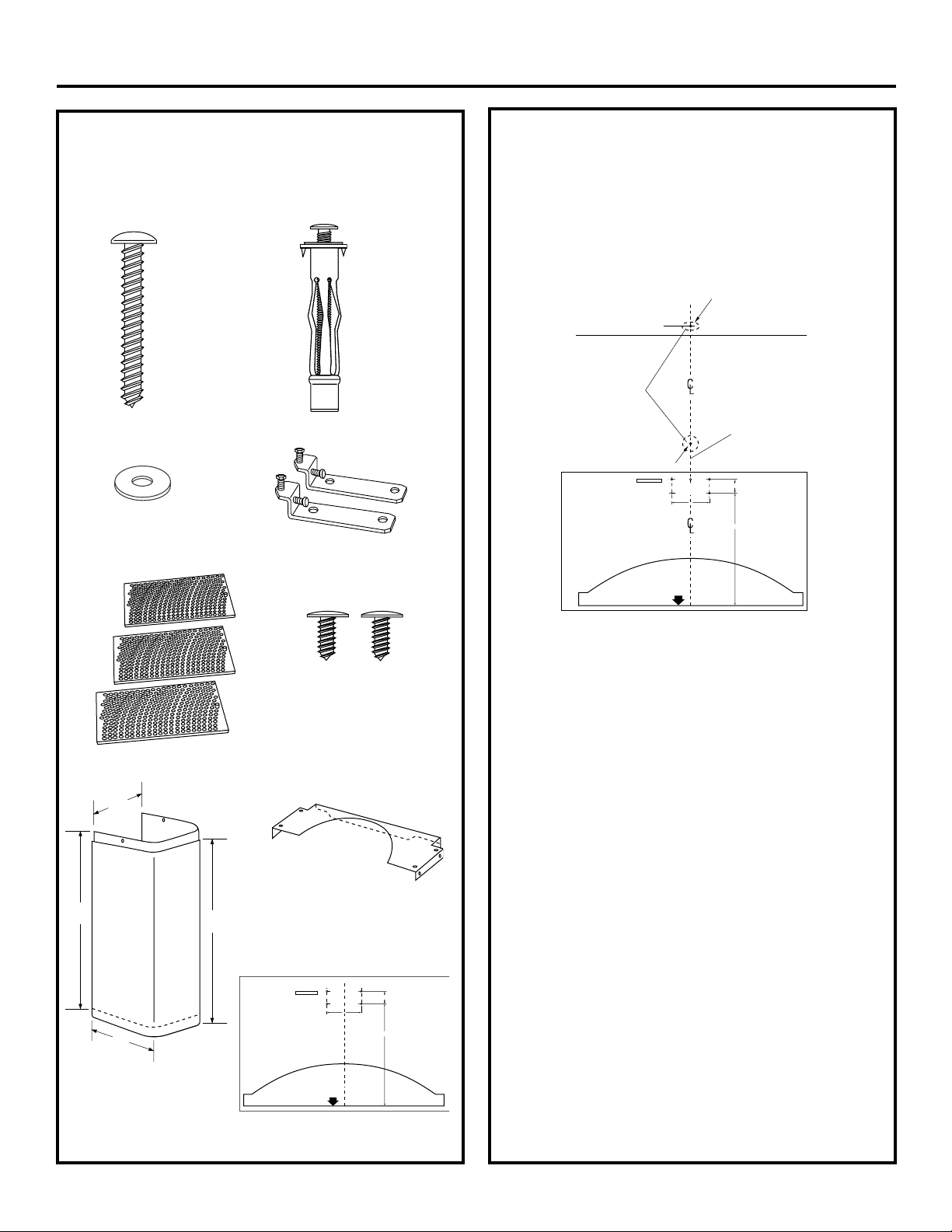
• Drill 1/8" Pilot Holes For Mounting Brackets.
Centerline
8" Min. Above
Top Mounting
Bracket Holes
6-1/4"
Centerline To Wall
FOR WALL VENT DUCT
FOR CEILING
VENT DUCTING
Align edge 25-1/2" above Cooking Surface.
17-1/2"
2-5/32"
C
L
5-7/8"
8-1/2" Dia. Hole
• Drill 1/8" Pilot Holes For Mounting Brackets.
Align edge 25-1/2" above Cooking Surface.
13-9/16"
2-5/32"
C
L
C
L
C
L
5-7/8"
Installation Preparation
16"
23"
11"
24"
CHECK INSTALLATION HARDWARE
Locate the hardware accessory box packed with the hood
and check contents.
10 Wood
Screws
2 Large
Flat Washers
2 Mounting Brackets with 4
Hex Head Leveling Screws
6 Wall
Fasteners
DUCTWORK, WIRING LOCATIONS
Determine the exact location of the vent hood.
• Locate the template packed with the literature.
– Measure 36" from the oor to the top of the cooking
surface. Add 25-1/2" (or other recommended space)
from the cooking surface to the bottom of the hood.
Mark that location.
– Use a level to draw a straight pencil line on the wall.
3 Stainless Steel Grease Filters
Decorative Duct Cover
(dimension shown
for reference only)
2-piece
2 Phillips Head
Decorative Screws
Duct Cover Bracket
Wall Mount Template
– Tape the template in position along the penciled line.
CHECK TO BE SURE THE TEMPLATE IS LEVEL.
Ceiling ducting:
If ductwork will vent straight up to the ceiling:
• Use a level to draw a line straight up, from the
centerline on the template to the ceiling.
• Measure 6-1/4" from the back wall to the centerline of
a 8-1/2" hole on the ceiling.
Note: If drywall is not present, add drywall thickness
to the 6-1/4" dimension.
Wall Ducting:
If ductwork will vent to the rear:
• Use the level to draw a line straight up from the
centerline on the template.
• Measure at least 8" above the top mounting bracket
holes shown on the template to the centerline of an
8-1/2" dia. duct hole. (Hole may be elongated for duct
elbow.)
HOUSE WIRING LOCATION:
• The junction box is located on the top of the hood, at
the back right side.
• Route house wiring as close to the ceiling location as
possible, through the ceiling, sot or back wall. Wiring
should enter at least 4" above the bracket on the right
side (no less than 18" above the planned lower edge of
hood and ideally, 4" to the right of planned ductwork.)
8
Page 9
Installation Instructions
Centerline of
Installation
Space
8" Min. Opening for Ductwork
View From Rear
Cleats
1" x 6" Min.
Mounting
Support
Screws
“B”
Screws
“A”
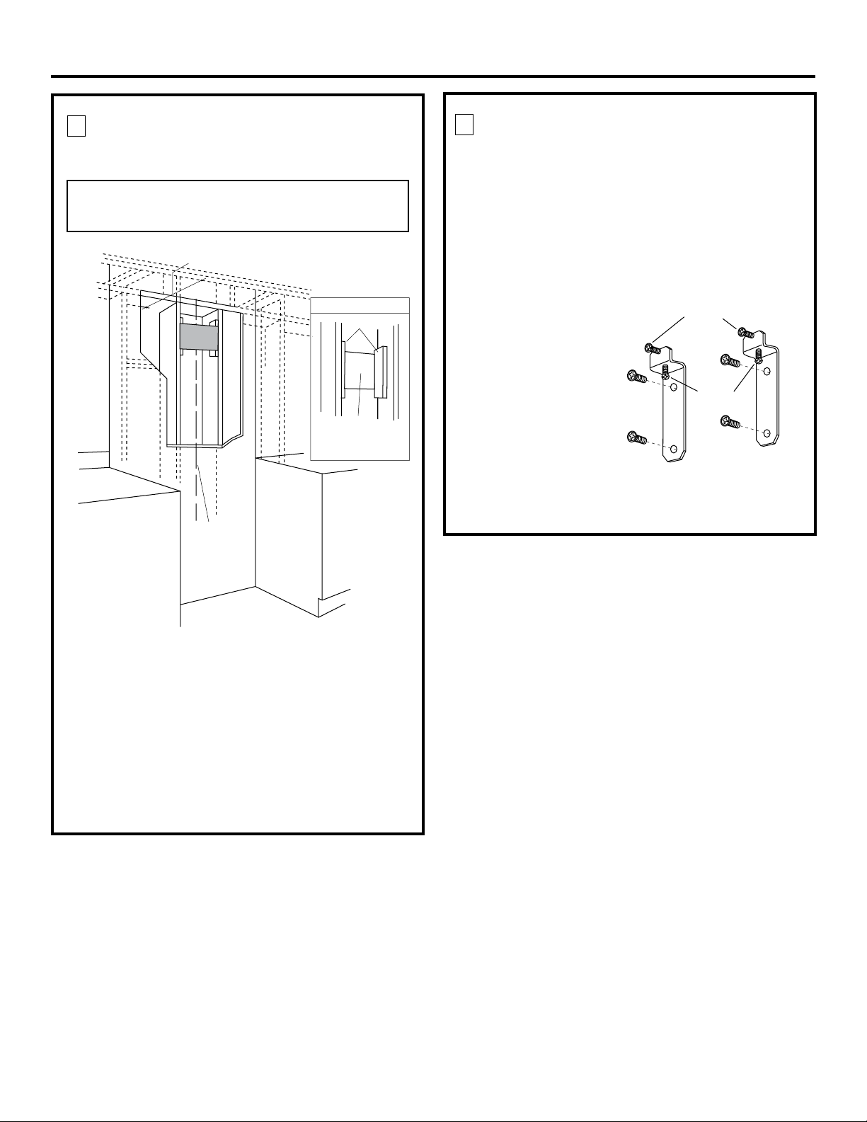
1 INSTALL FRAMING
FOR HOOD SUPPORT
IMPORTANT: Framing must be capable
of supporting 100 lbs.
2 INSTALL MOUNTING BRACKETS
This vent hood must be secured to the horizontal support or
wall studs.
• With the template taped in place, use a punch to mark
all mounting screw locations.
• Drill 1/8" pilot holes at the 6 punched locations.
• Remove the template.
• The 4 support bracket holes must enter studs or the
horizontal support.
Note: Screws “A” and “B”
are pre-assembled onto
the brackets. Do not
remove these screws.
• Secure the mounting brackets to the wall studs with
wood screws provided.
If drywall is present, mark the screw hole locations for the
top mounting brackets. Remove the template.
• Cutaway enough drywall to expose 2 vertical studs at the
bracket location indicated on the template.
• Install a horizontal support at least 1" x 6" between two
wall studs at the top bracket installation location. The
horizontal support must be ush with the room side of
the studs. Use cleats behind both sides of the support
to secure the support to wall studs.
• Reinstall drywall.
9
Page 10
Pre-Tap
Side
Screw
Pre-Tap
Side
Screw
Bracket Tabs
Screws
“B”
Screws
“A”
Installation Instructions
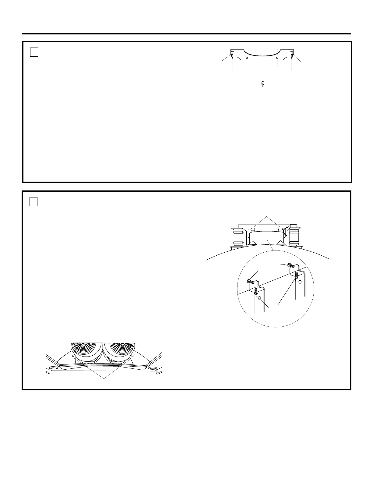
3 INSTALL DUCT BRACKET
The duct bracket must be installed against the ceiling. This
bracket will hold the decorative duct cover in place at the
top.
• Install the 2 small screws into the sides of the duct
bracket. Remove the screws. Pre-tapping the holes will
insure ease of nal installation.
Secure the bracket to the ceiling and wall:
• Mark the 4 screw hole locations.
• Drill 1/8" pilot holes in marked bracket location.
• If pilot holes do not enter studs, enlarge the holes to 3/8"
and install wall fastener anchors.
• Drive screws, by hand, into the fasteners to allow
anchors to expand. Remove the screws.
• Secure the bracket to the ceiling and wall with wood
screws and/or fasteners.
4 INSTALL THE HOOD
Place the hood on the brackets and slide left or right to
center.
1. Adjust the installation levelness by tightening or
loosening the screws “A” at the bottom of the brackets.
2. Mark the 2 lower mounting holes.
3. Remove the hood from the wall.
4. Drill a pilot hole in each lower mounting hole location.
The two lower holes can be enlarged to 3/8" if they did
enter studs. Tap anchors for wall fasteners into the bottom holes. Screws should be inserted by hand into the
fasteners to allow anchors to expand against the wall
material. Remove the screws for nal installation.
5. Replace the hood on the mounting brackets.
6. Using two large at washers (supplied), install wood
screws or wall fastener screws.
7. Tighten screws “B” located at the top of the mounting
bracket against the hood to clamp the position. Do not
overtighten screws.
Lower Mounting Holes
10
Page 11
Installation Instructions
Mounting Screws
Screw
Duct Tape
Over Seam
and Screw
Air Flow
Duct Tape
Over Flange
Duct Stops
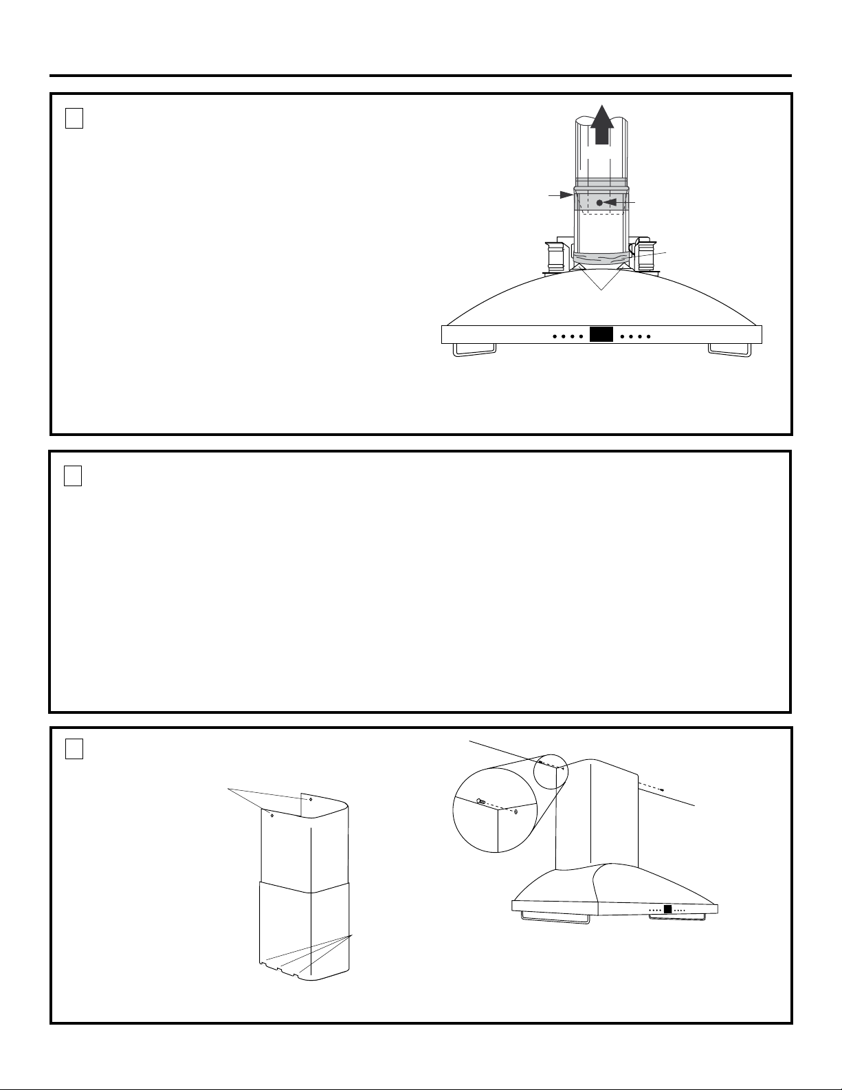
5 CONNECT DUCTWORK
• Install ductwork, making connections in direction
of airow as illustrated.
• Push duct over the exhaust outlet until it reaches
the duct stops.
• Secure joints in ductwork with sheetmetal screws.
• Wrap all duct joints with duct tape for an airtight seal.
• Use duct tape to seal the ange connection.
CAUTION: Do not use sheet metal screws at
the hood ange connection. Doing so will prevent proper
damper operations. Seal connection with tape only.
PRUDENCE
Il ne faut pas utiliser de vis autoraurdeuses à la connexion
du collet de la hotte. Ceci empêcherait le bon
fonctionnement du registre. N’utiliser que du ruban adhésif
pour assurer l’étanchéité du raccord.
6 CONNECT ELECTRICAL Verify that power is turned o at the source.
WARNING: If house wiring is not 2-wire with a
ground wire, a ground must be provided by the installer.
When house wiring is aluminum, be sure to use U.L. approved anti-oxidant compound and aluminum-to-copper
connectors.
AVERTISSEMENT
Si la maison n’est pas câblée avec deux ls et un l de
terre, l’installateur doit installer un l de terre. Quand les ls
sont en aluminium, il faut prendre soin d’utiliser des connecteurs aluminium à cuivre avec une pâte antioxydante
approuvée par UL.
7 INSTALL DUCT COVERS
• Place the decorative duct
covers on top of the hood.
• Insert the lower portion
of the duct cover into the
impressions on the top of
the hood.
Bottom
Notches
• Insert house wiring through strain relief and tighten.
• Connect white leads to branch circuit white lead.
• Connect black leads to branch circuit black lead.
• Connect green/yellow leads to branch circuit green lead
or bare ground lead.
• Secure all connections with wire nuts on each electrical
connector.
• Push wires into junction box and replace cover. Be sure
wires are not pinched.
• Extend the inner duct upwards to the ceiling bracket.
• Secure the duct cover to the bracket with the 2 small
Phillips screws provided.
11
Page 12
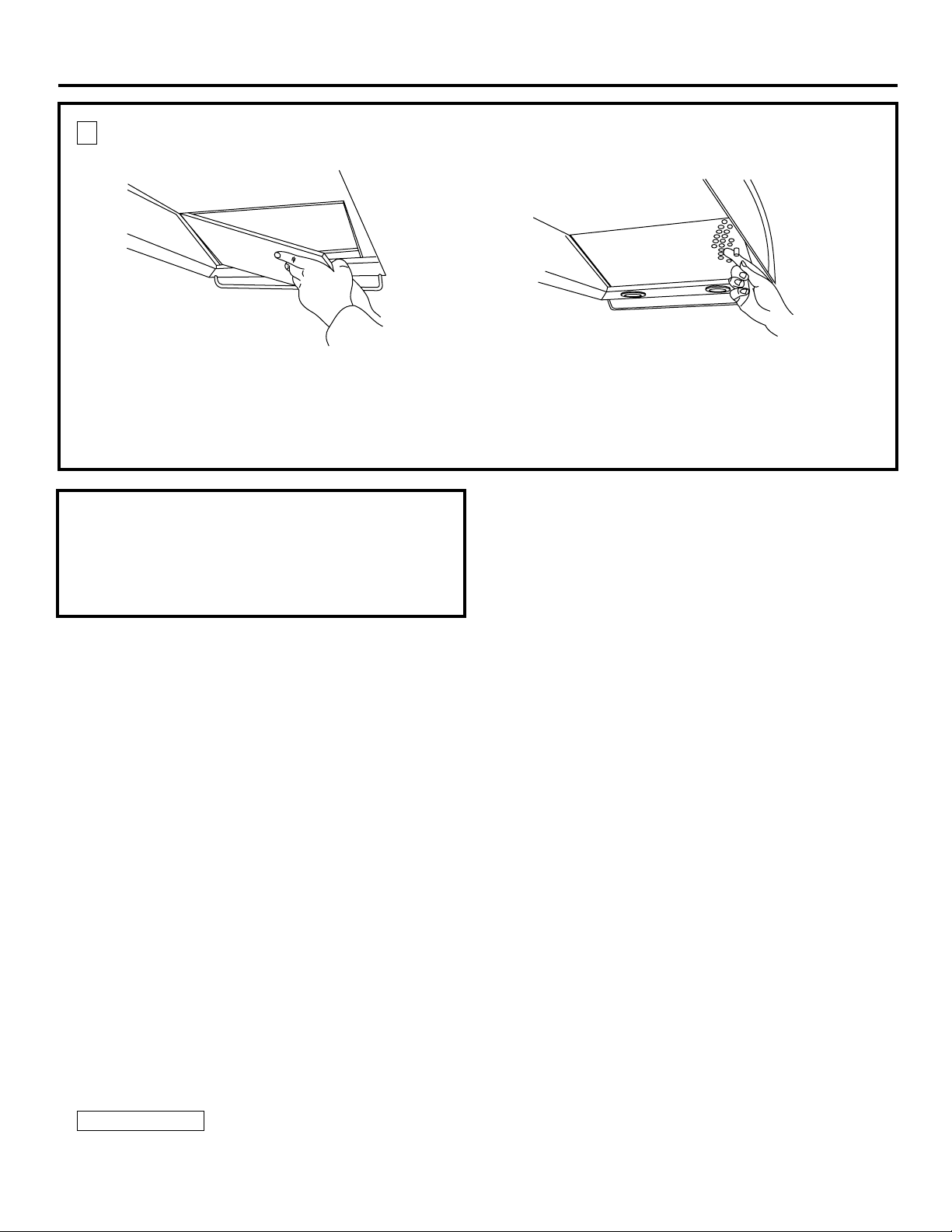
8 INSTALL FILTERS
• Remove protective lm on the lters.
Installation Instructions
• Tip the lter into the slots at the rear of the opening. Lift
the lter and pull the knob forward until the lter rests on
the slots.
• Install all 3 grease lters.
9 FINALIZE INSTALLATION
• Remove the protective lm covering the control panel
on the front face of the hood, and any other packaging
materials.
• Refer to the Owner’s Manual for operating instructions.
• To remove the lters, grasp the knob, push the lter towards the rear and tilt downwards.
• If the Clean Filter Reminder is glowing red after lters are
installed, be sure to check the left side lter is making
contact with the lter switch.
Pub. No. 31-14900
10-10 GE
Printed in Italy
Note: While performing installations described in this book,
safety glasses or goggles should be worn.
For MonogramTM local service in your area, call
1.800.444.1845.
Note: Product improvement is a continuing endeavor at
General Electric. Therefore, materials, appearance and
specications are subject to change without notice.
 Loading...