

Page 1
C
GE Consumer Service T raining
TECHNICAL SER VICE GUIDE
Monogram® Wall-Mounted
and Island Hoods
MODEL SERIES:
ZV750
ZV850
PUB # 31-9043 03/00
Page 2

!
IMPORTANT SAFETY NOTICE
The information in this service guide is intended for use by
individuals possessing adequate backgrounds of electrical,
electronic, and mechanical experience. Any attempt to repair a
major appliance may result in personal injury and property
damage. The manufacturer or seller cannot be responsible for the
interpretation of this information, nor can it assume any liability in
connection with its use.
CAUTION
To avoid personal injury, disconnect power before servicing this
product. If electrical power is required for diagnosis or test
purposes, disconnect the power immediately after performing the
necessary checks.
RECONNECT ALL GROUNDING DEVICES
If grounding wires, screws, straps, clips, nuts, or washers used
to complete a path to ground are removed for service, they must
be returned to their original position and properly fastened.
GE Consumer Service Training
Technical Service Guide
Copyright © 2000
All rights reserved. This service guide may not be reproduced in whole or in part
in any form without written permission from the General Electric Company.
Page 3

Table of Contents
Hood Nomenclature ............................................................................................ 2
Features ...............................................................................................................3
Installation Highlights.........................................................................................3
Controls ...............................................................................................................5
Use and Care Information .................................................................................. 8
Halogen Lamp Assembly Replacement ............................................................ 9
Filter Replacement ..............................................................................................9
Component Access/Duct Cover Removal......................................................... 9
Control PCB Replacement ................................................................................. 10
Entry/Display Assembly Replacement .............................................................. 11
Filter Microswitch Replacement1 ......................................................................11
Fuse Replacement .............................................................................................. 12
Glass Visor Replacement ...................................................................................12
Motor & Blower Assembly Replacement .......................................................... 13
Motor Capacitor Replacement ........................................................................... 14
Transformer Replacement.................................................................................. 15
Triac Replacement ..............................................................................................16
Troubleshooting .................................................................................................. 17
Schematic & Strip Circuits .................................................................................18
Model ZV750 Illustrated Parts Breakdown ....................................................... 22
Model ZV850 Illustrated Parts Breakdown ....................................................... 24
Warranty Information..........................................................................................27
– 1 –
Page 4
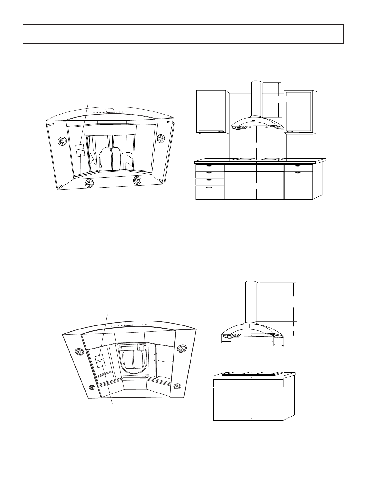
Hood Nomenclature
*
7
ZV750
Nomenclature
25-1/2" Recommended
36" Min.
Mini Manual
Locator Label
ZV750Y1: Early model wall-mounted hood.
ZV750Y2: Later model wall-mounted hood with motor
mount similar to Island-mounted hood.
Height to Ceiling*
GEA0002
ZV850
Height
to Ceiling
Nomenclature
8-1/4"
35-3/8"
25-1/2" Recommended
Mini Manual
Locator Label
*Duct covers are available as necessary accessory kits to accomodate installations with 8-, 9-, or 10-foot ceilings.
36" Reference
27-1/2"
GEA00028
– 2 –
Page 5

Features
Stainless Steel Finish
36-Inch Width
350 CFM V ertical Exhaust Blower Rating
Electronic T ouchpad Controls
4 Halogen Lamps
3 Removable Filters with 30-Hour Filter Cleaning Reminder
6-Inch Round Duct
Model ZV750 W all Mount
Model ZV850 Island Mount
Installation Highlights
Mount Dimensions and Clearances
(See Hood Nomenclature)
The vent hood must be installed at least 24 inches and not more than 30 inches above the cooking surface.
25-1/2 inches is recommended to ensure that the duct cover meets the ceiling. The cooking surface should
be at least 36 inches above the floor .
Electrical Wiring
WARNING: Remove house fuse or open circuit breaker before beginning installation. Do not use an
extension cord or adapter plug with this appliance. Follow national electrical codes or prevailing local codes
and ordinances.
Electrical Supply
The vent hood must be supplied with 120V, 60Hz electrical power, and connected to an individual, properly
grounded branch circuit, protected by a 15- or 20-ampere circuit breaker or time delay fuse.
• Wiring must be 2-wire with ground.
• If electrical supply does not meet the above requirements, call a licensed electrician before proceeding.
• Route wiring as close to the installation location as possible, in the ceiling or soffit.
• Connect the wiring to the house wiring in accordance with local codes.
– 3 –
Page 6
Grounding Instruction
in
n
WARNING: The improper connection of the equipment-grounding conductor can result in a risk of electric
shock. Check with a qualified electrician if you are in doubt whether the appliance is properly grounded.
The grounding conductor must be connected to a metal ground, permanent wiring system, or an
equipment-grounding terminal or lead on the hood.
Exhaust Ducting
The hood uses 6-inch metal ducting to exhaust fumes. Refer to the vent hood installation instructions for
details of the maximum permissable lengths to be used for duct runs to outdoors. Do not exceed the
maximum permissable equivalent length total of 100 feet for a range hood.
Flexible 6-inch metal ducting may be used. When flexible ducting is used, all equivalent feet values of
components must be doubled. The flexible metal duct should be straight and smooth and extended as
much as possible. Do not use flexible plastic ducting.
Note: Any home ventilation system, such as a ventilation hood, may interrupt the proper flow of combustion air and exhaust required by fireplaces, gas furnaces, gas water heaters, and other naturally vented
systems. To minimize the chance of interruption of such naturally vented systems, follow the heating
equipment manufacturer’s guidelines and safety standards such as those published by NFPA and ASHRAE.
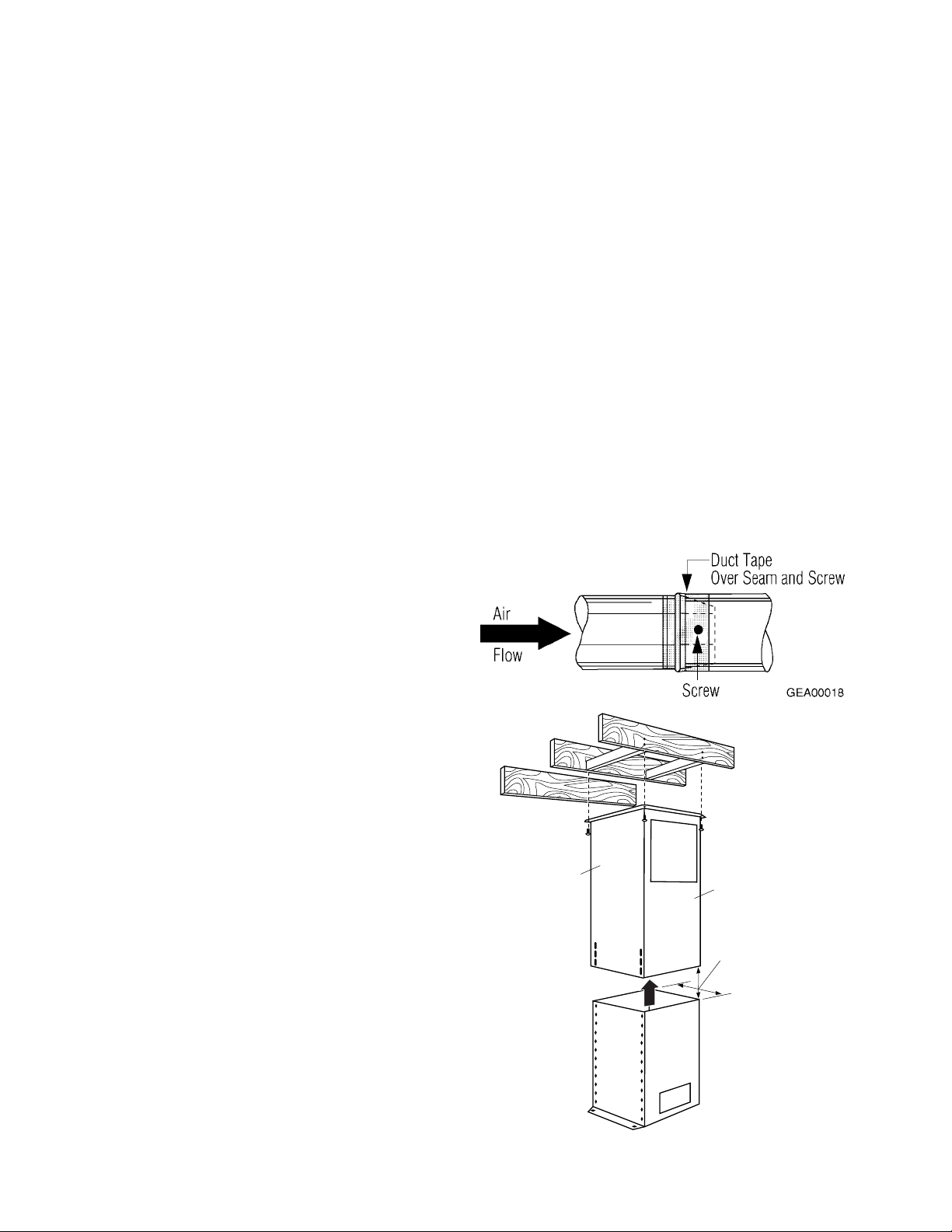
Install all ductwork by making joint connections
in the direction of the air flow as illustrated.
Secure the joints with sheetmetal screws. Wrap
the joints with duct tape for an airtight seal.
Model ZV 850
This model is installed using 1 of 3 installation
kits (for 8-, 9-, or 10-foot ceilings). The upper
support frame (shown at right) is secured to the
ceiling joists and/or cross framing with 4 screws.
The support frame must be level and square.
The lower support frame slips into the upper
frame and can be adjusted up or down to the
desired height. It is secured with 8 screws and
washers.
Upper
Support
Frame
Lower
Support
Frame
Front
Of
Hood
Support
Frame
Opening
Check Level
Both Directio
– 4 –
GEA00116
Page 7
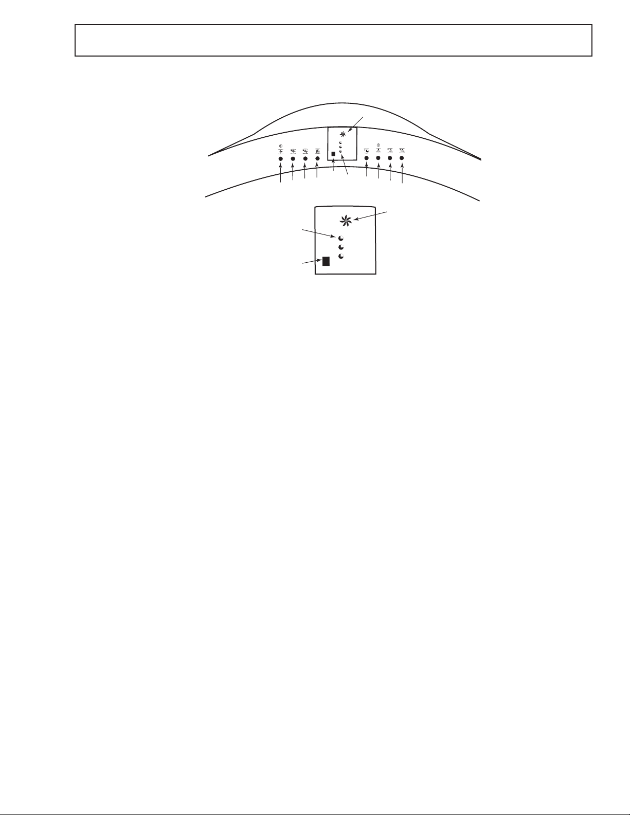
CONTROLS CONFIGURATION
4
Fan Keypad Operation
Controls
4
3
2
1
10
9
11
9
10
5
6
7
8
11
05
10
20
GEA0001
1. ON/OFF Switch - T urns electrical power to motor on and off. Remembers the last fan speed used.
2. Decrease Speed - Decreases current fan speed (4 speeds).
3. Increase Speed - Increases current fan speed (4 speeds).
4. High Speed - Maximum fan speed (350 cfm).
5. Delayed Shut-off - Choose 5-, 10-, or 20-minute shutdown time by pushing this button. Time is
indicated by illumination of Delay Shut-off Indicators (10).
Hood Lights Keypad Operation
6. Light ON/OFF - T urns electrical power to light on and off. Remembers the last light level used.
7. Decrease Brightness - Dims lights in 6 light levels.
8. Increase Brightness - Brightens lights in 6 light levels.
Display LEDs
9. Filter Cleaning Reminder Indicator - Lights after 30 hours of “on” time to remind you to clean the
metal grease filters. The light blinks until the filters are replaced. The timer reset s automatically.
10. Delayed Shut-off Indicators - Indicates delayed time setting. The fan will shut of f automatically at the
end of the delayed time setting.
11. Fan Operating Symbol - When illuminated, indicates that the fan is in operation even if the noise of
the fan cannot be heard.
– 5 –
Page 8
ELECTRONIC HOOD CONTROL DESCRIPTION
6
C
T
5
The electronic hood control system consists of the following parts: Entry/Display Assembly; Control PCB;
Triac; Fuse Holder; Motor Cap acitor; Transformer; Halogen Lamps; Filter Microswitch; and Induction Fan Motor.
CAUTION: Components are electrically HOT on the electronic control when voltage is connected to the
hood even though the ON/OFF switch is in the OFF position.
Entry
Control
Enclosure
GEA0001
1. ENTRY/DISPLAY ASSEMBLY
The replacement assembly WB27X10345 has 3 Printed Circuit Boards (PCB) mounted in a plastic enclosure with 8 push buttons and a ribbon cable. The three PCBs are Fan Touch Control PCB, Lamp Touch
Control PCB, and Display PCB.
Note: Before replacing the assembly, check the operation of the other hood components by plugging the
new Entry/Display Assembly cable into connector CN5 on the Control PCB. If the unit does not work,
replace the control board first and then recheck whether the existing Entry/Display assembly is OK. The
harness in the hood can be used instead of the one supplied with the assembly by carefully removing the
five screws from the enclosure assembly and unplugging the cable.
Black Box
Fuse Holder
ontrol PCB
ransformer
Motor Capacitor
Note: Mini Manual
on Control PCB
Cover.
1/4"
Terminals
Brown
Triac
Black
3/16"
Terminal
Orange
Brown
3/16"
Terminal
Orange
Motor
Capacitor
1/4"
Terminals
Black
Triac
Control PCB
ZV750 ZV850
Note: Mini Manual
on Control PCB
Cover.
Black Box
Fuse Holder
GEA0001
2. CONTROL PCB
This PCB has an AC to DC power supply, microprocessor, and fan relays and is located in the black box in
the hood chimney area.
Note: The 5 green connectors are locking type. Use a small flat blade screwdriver to unlock as follows:
Insert screwdriver in the center of the space between the plug and connector receptacle on the PCB. Push
down on the screwdriver handle to pivot blade about 5 degrees and pull out the plug at the same time.
TO CHECK OPERATION OF CONTROL PCB:
Check that all 6 connectors are locked in place, no leads are broken, and connector solder joints are not
broken on PCB copper tracks.
– 6 –
Page 9
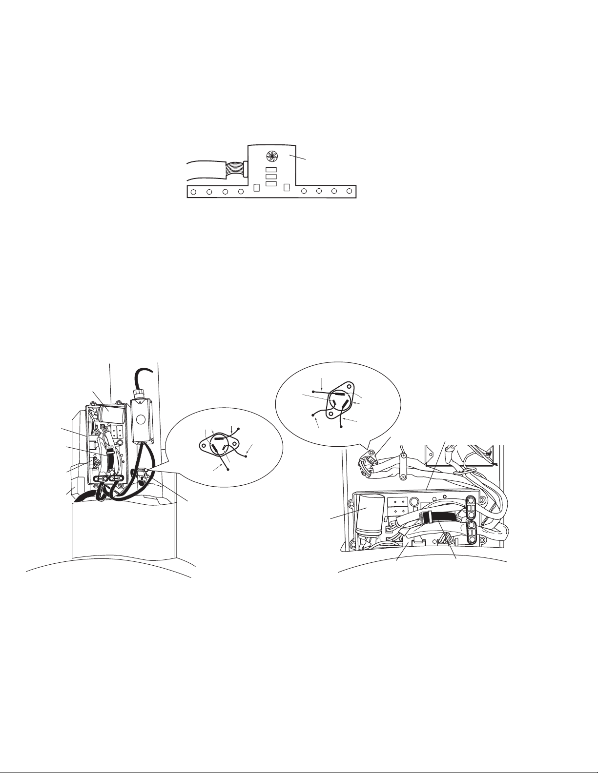
3. TRIAC
E
7
The triac controls the four hood lamps and is mounted in a box in the chimney area. T riac has an isolated
case, which is mounted to the chimney with two screws.
Note: Triac wire connection must be correct or lamp flickering could occur. Triac can be checked for electrical short by removing the black lead and measuring the resistance between the two 1/4" terminals (terminals with black and brown wires). Resistance should be greater than 1M ohm.
4. FUSE HOLDER
The fuse holder is an in-line type, which is in series with 12V AC from the transformer and is located in the
blackbox. An open fuse may be caused by a lamp failing or a wrong wattage lamp.
Note: The fuse is 5 x 20 mm and rated at (8) A, 250V AC (GE part number WB02X10584).
5. MOTOR CAPACITOR
The start/run capacitor is mounted in the black box and plugs into the Control PCB connector CN3.
ntry/Display Assembly Filter Microswitch
AA
4 Lamps
Fan Motor
Lamps (4)
ZV750 ZV850
Transformer
Fan Motor
Motor mtg.-4 Hex Screws
(Use 9/32" Socket With Extension)
Entry/Display Assembly
A
A
Filter
Microswitch
6. TRANSFORMER
The transformer provides 12V AC to the hood lamps and the Control PCB power supply. It is attached by
four screws from the top of the chassis. The transformer is located next to the black box in Model ZV750
and above the grease filter in Model ZV850.
7. HALOGEN LAMPS
The 4 halogen lamps are the push-in type and rated at 12V AC/20W. The equivalent GE lamp is a
Q20MR16/C/CG40 - BAB.
GEA0001
8. FILTER MICROSWITCH
The microswitch is mounted in the filter area. When filters are removed, the microswitch causes the red
display light to blink continously. The red display light will also turn “on” after 30 hours of fan operation to
remind the user to clean the filters. Make sure the filter is seated properly when installed, or the filter light
will blink. NOTE: If electrical power is lost, the timer automatically resets to 0.
9. INDUCTION F AN MOT OR ASSEMBL Y
The motor is a 4-speed, start/run capacitor, induction type rated at 120V AC/1.7A. Motor stator winding
resistances:
Orange-Red = 17 ohms Blue-White = 8.5 ohms
Blue-Black = 17 ohms Black-White = 8.5 ohms
– 7 –
Page 10

Use and Care Information
9
N
f
b
u
If the consumer has any questions that the service person cannot answer, refer them to the GE Answer
Center (800.626.2000).
Care and Cleaning Stainless Steel Hood
WARNING: Before servicing or cleaning the unit, switch power off at the service panel and lock the
service panel to prevent power from being switched on accidentally. If the service panel cannot be
locked, fasten a tag or prominent warning label to the panel.
Metal Grease Filter
Note: To remove filters, push them back and down
using the knob.
ote:
To remove
ilters push them
ack and down
sing the knob.
Clean the grease filter after 30 hours of “on” time. A
signal light will alert you when 30 hours have passed.
Remove the grease filters and wash them either by
hand or in the dishwasher using
nonabrasive soap.
GEA0001
Note: If electrical power is lost, the timer automatically resets to 0.
For proper operation, be sure to use the lower set of
filter channels to assure that the microswitch is set.
Hood Surface
To clean the hood surface, use hot soapy water, then rinse and dry. For greasy soil, use an all-purpose
cleaning spray such as Fantastik
steel cleaner such as Bon-Ami®, Cameo®, or Barkeepers Friend®. Always scrub lightly and with the grain.
Do not use steel wool pads or other abrasive cleaners; they will scratch the surface.
®
brand or Formula 409® brand. For hard to clean soil, use a stainless
– 8 –
Page 11

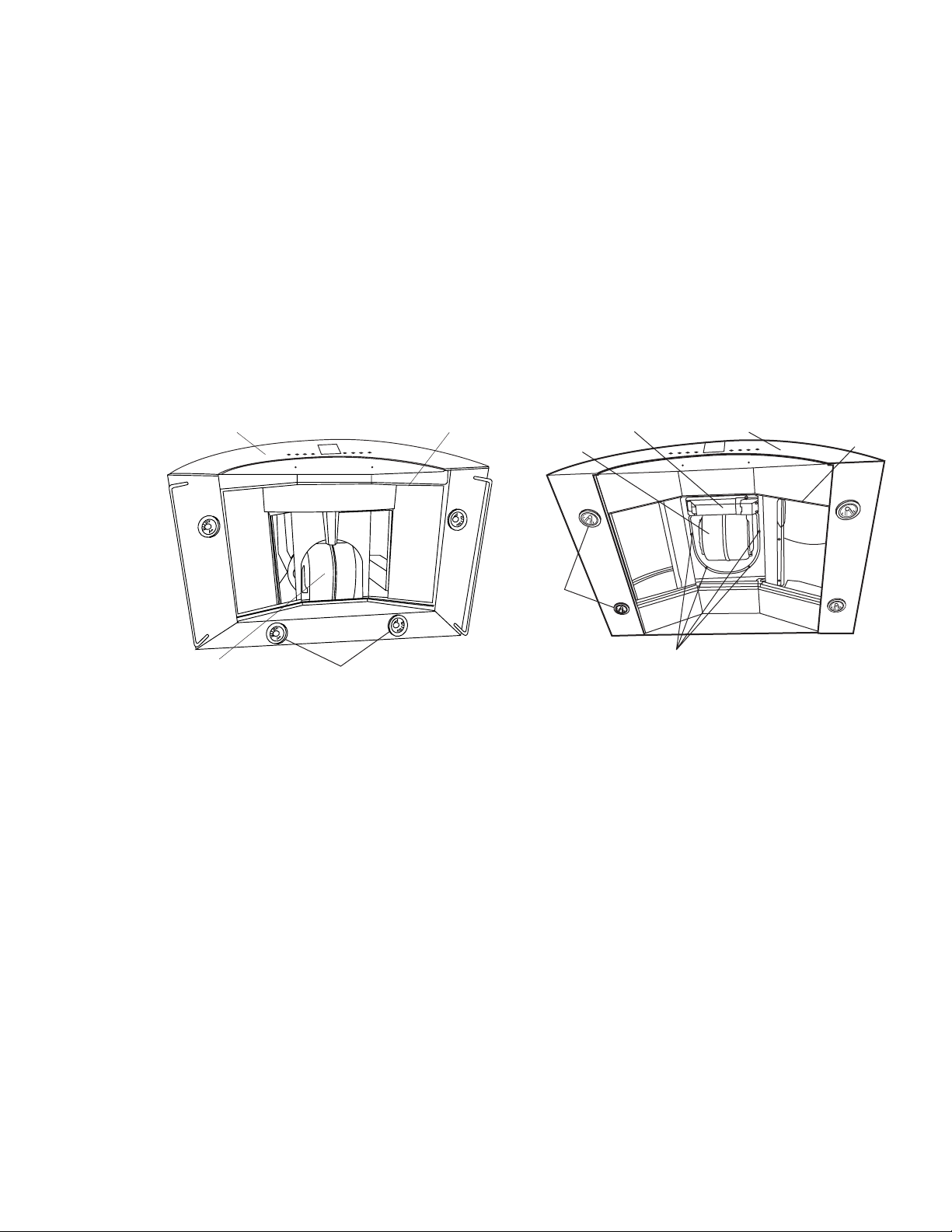
Halogen Lamp Assembly Replacement
7
5
Service
Manual
Envelope
Triac
Junction
Box
Transformer
Black Box
(Control PCB)
ZV750 GEA00006
1. Remove the ring nut by turning it counter clockwise.
2. Grasp the bulb on the edges and pull it
straight out.
3. Remove 3 filters from the fan housing.
4. Remove 2 screws and lamp protection
from the hood.
5. Disconnect wires from lamp socket.
CAUTION: Replace the lamp with the same
size bulb. These 12-volt, 20-watt halogen bulbs
are available at specialty lighting stores. Ask for
GE bulb or equivalent: Q20 MR16/FL 40°–BAB.
Note: When reinstalling, ensure that all electrical
connections are securely fastened.
Filter Replacement
(Access to lighting and wiring)
1. Grasp knob and push filter back into rear
recess to release front edge of filter from track.
2. Pull front edge of filter down.
3. Pull filter toward you to remove.
GEA0000
Component Access/Duct Cover Removal
Model ZV750, Wall-Mounted Hood
Note: A ladder or step stool is needed for the
following procedure.
1. Remove 2 screws from the top duct cover at
the ceiling and slide the top cover down (see
illustration).
2. Lift and remove both duct covers. Set covers
aside.
GEA0000
– 9 –
Page 12

Component Access/Duct Cover Removal
er
7
B
Model ZV850, Island Hood
WARNING: Stop screw must be installed in one
of the support frame holes. Failure to do so may
cause personal injury or damage to duct cover.
1. Lift the lower duct cover up into the upper duct
cover (see illustration).
2. Remove the stop screw from the service
manual envelope.
3. Install stop screw in 1 of the holes provided in
the support frame to secure the lower duct
cover.
Note: Return the stop screw to the service manual
envelope when service is complete.
Control PCB Replacement
Install Stop
Screw In One
of 3 Holes
Provided
Triac
Bottom
Duct
Cover
AC Pow
Junction
Box
Service
Manual
Envelope
Black Box (Control PCB)
GEA00002
Motor Capacitor
lack Box
Control PCB
Motor
Capacitor
Control PCB
Black Box
ZV850ZV750
GEA0011
1. Access black box (refer to Component Access/Duct Cover Removal).
2. Disconnect motor capacitor connection from terminal CN3.
3. Disconnect entry/display assembly cable from terminal CN5.
4. Disconnect filter microswitch and triac connector from terminal CN4A.
5. Disconnect transformer and fuse connector from terminal CN4B.
6. Replace control PCB with new control PCB.
Note: When reinstalling, ensure that all electrical connections are securely fastened.
– 10 –
Page 13

Entry/Display Assembly Replacement
E
7
9
5
ntry/Display Assembly Filter Microswitch
Transformer
Fan Motor
AA
4 Lamps
Fan Motor
Lamps (4)
Motor mtg.-4 Hex Screws
(Use 9/32" Socket With Extension)
ZV750 ZV850
1. Remove 3 filters from hood.
2. Remove 2 screws (A) from hood and entry/display assembly .
3. Remove entry/display assembly from hood.
4. Remove the pusher bracket holding the display in place on
the face of the hood.
5. Remove the entire display .
Entry/Display Assembly
A
A
Filter
Microswitch
GEA0001
Entry
Control
Enclosure
GEA0001
Note: When reinstalling, ensure that all electrical connections are securely fastened, and the pusher
bracket and 2 screws are installed correctly. Check to be sure that the push buttons move freely through
the front surface of the control panel.
Filter Microswitch Replacement
Filter Microswitch
A
B
Note: Model ZV750Y1 is shown; Model ZV750Y2 and later , and Model ZV850 have only one filter
microswitch.
1. Disconnect electrical power to hood assembly .
2. Remove 2 screws (A) and filter microswitch bracket (B) from fan.
3. Remove 2 screws (C) and microswitch box from bracket.
4. Remove microswitch (D) from microswitch box and cover.
5. Disconnect wires from microswitch.
6. Replace microswitch with new microswitch.
C
D
GEA0002
Note: When reinstalling, ensure that all electrical connections are securely fastened.
– 11 –
Page 14

Fuse Replacement
9
B
lack Box
Fuse Holder
1. Access black box (refer to Component Access/
Duct Cover Removal).
2. Remove 4 screws and cover from black box.
3. Remove cap and fuse from fuse holder.
4. Replace fuse with new fuse.
Fuse Holder
ZV850ZV750
Black Box
GEA0011
WARNING: The fuse is a 5 x 20 mm and is rated
at 8 amps, 250V AC. Replace with fuse of the
same rating only (GE part number WB02X10584).
Glass Visor Replacement
Note: Model ZV750 hood has 1 glass visor and the
ZV850 has 2 glass visors.
1. Remove the plastic screws from the range hood.
2. Remove glass visor(s) from hood.
GEA00032
– 12 –
Page 15

Motor & Blower Assembly Replacement
F
M
1
B
d
s
Mounting Screw
GEA00121
Model ZV750
Note: This procedure requires that the unit be
removed from the wall.
ZV750
Entry/Display Assembly
Wire Shield/Wire Guide
Filter Microswitch
1. Remove duct cover (refer to Component
Access/Duct Cover Removal).
2. Disconnect power supply and exhaust ducting.
Note: Two people are required to perform the
next step.
3. While an assistant supports the hood, remove
2 lower mounting screws and the hood from
the wall.
4. Remove 4 screws (A) from the exhaust
opening.
5. Remove the black box cover ( 4 screws).
6. From the black box, remove the following:
a. 2 wire restraints (2 screws each)
b. wires from motor to Control PCB
(unplug terminal CN1)
c. ground wire
7. Remove green ground wires from ground
post.
8. Remove the blower assembly from the
hood (4 screws).
9. Remove the split ring from around the motor
wires and turn the plug sideways to remove.
an
otor
A
A
Lamps (4)
Change
Lamps
A
A
GEA0001
Note: Test motor before reinstallation.
Motor Capacitor
Note: When reinstalling, ensure that all
electrical connections, including ground
connections, are securely fastened.
lack Box
Control PCB
ZV750
Groun
Wire
GEA00117
– 13 –
Page 16

Motor & Blower Assembly Replacement
4
4
7
B
Model ZV850
1. Raise duct cover (refer to Component
ZV850
Access/Duct Cover Removal).
2. Remove filters (refer to Filter Replacement).
3. Remove the black box cover (4 screws).
Transformer
Entry/Display Assembly
4. From the black box, remove the following:
a. 2 wire restraints (2 screws each)
Fan Motor
b. wires from motor to Control PCB
(unplug terminal)
c. ground wire
5. Remove green ground wires from ground
post.
6. Remove retaining bracket and wire guide
(3 screws and split ring).
7. Remove the blower assembly from the
Lamps
Motor mtg.-4 Hex Screws
(Use 9/32" Socket With Extension)
hood (4 screws).
Note: When reinstalling, ensure that all electrical connections, including ground
connections, are securely fastened.
Filter
Microswitch
Change
Lamps
GEA0000
Motor Capacitor Replacement
Motor Capacitor
lack Box
Control PCB
Motor
Capacitor
Control PCB
1. Access black box (refer to Component Access/Duct Cover Removal).
2. Remove 4 screws and cover from black box.
3. Unplug connector from control PCB connector CN3 and remove motor capacitor from black box.
4. Replace motor capacitor with new motor capacitor.
Black Box
ZV850ZV750
GEA0011
Note: When reinstalling, ensure that all electrical connections are securely fastened.
– 14 –
Page 17

1
Transformer Replacement
8
T
B
(
lack Box
Control PCB)
ransformer
Service
Manual
Envelope
Transformer
Junction
Box
Triac
ZV750 ZV850
Note: Model ZV750 transformer is located above
the hood; Model ZV850 transformer is located
inside the hood.
1. Access transformer (refer to Component
Access/Duct Cover Removal).
2. Remove 2 screws and cover from transformer.
3. Loosen 4 screws and remove 5 wires from
transformer.
Note: Model ZV750 transformer does not have
an external ground wire; Model ZV850 trans former has an internal green ground wire
attached to the lower ground screw.
4. Remove the 2 screws, nuts, and the
transformer from the hood assembly.
5. Replace the transformer with a new transformer.
Note: When reinstalling, ensure that all electrical
connections are securely fastened.
ZV750
GEA0011
GEA0003
– 15 –
Page 18

6
C
T
Triac Replacement
Brown
Motor Capacitor
Black Box
Fuse Holder
ontrol PCB
ransformer
1/4"
Terminals
Brown
Triac
ZV750 ZV850
Black
Orange
3/16"
Terminal
1. Access triac (refer to Component Access/
Duct Cover Removal).
Note: The triac is located on the right side of
Model ZV750 and on the front of Model ZV850.
See Electronic Hood Control Description for
ZV850 diagram.
3/16"
Terminal
Orange
Motor
Capacitor
1/4"
Terminals
Black
Triac
Control PCB
Black Box
Fuse Holder
GEA0001
2. Remove 2 screws and the triac cover from
the hood.
3. Unplug 3 connectors from the triac.
4. Remove 2 screws and the triac from the hood.
5. Replace the triac with a new triac.
Note: When reinstalling, ensure that all electrical
connections are securely fastened and in the
correct location (ref. – mini manual).
– 16 –
Page 19

Troubleshooting
N
SERVICE DIAGNOSTIC FLOWCHART
WARNING
POWER MUST BE DISCONNECTED
BEFORE SERVICING THE APPLIANCE
REMOVE
TRIAC
ORANGE
LEAD
YES
YES
DONE
YES
ORDER/
INSTALL
TRIAC
YES
FAN
OK?
LIGHTS
OK?
LIGHTS
ALWAYS
ON?
NO
LIGHTS
ON?
NO
NO
NO
HOOD
LIGHTS
FLICKERING?
NO
NO
NO
RED DISPLAY
YES
FIX/
ORDER
MOTOR
YES
CHECK/MODIFY
TRIAC
CONNECTIONS
HOOD
LIGHTS
FLICKERING?
ORDER/INSTALL
NO
PUSH BUTTONS STUCK?
NO
PUSH BUTTONS STUCK?
NO
LIGHT
BLINKING?
FAN BLADES
BLOCKED?
CONTROL
YES
REMOVE/
RE-SEAT
RIGHT
FILTER
NO
• CHECK FM CAP (CN3)
NO
• UNPLUG CN1, CHECK
FM RESISTANCE
• FM OK?
YES
INSPECT
PCB IN
BLACKBOX
NOTE #1
YES
PCBs
YES
HOOD
DONE
ORDER/INSTALL
ENTRY/DISPLAY
ASSEMBLY
& CONTROL
PCBs
OK?
NO
HOOD CONTROL
DEAD?
TRANSFORMER
ORDER/
INSTALL
YES
UNSTICK/ADJUST
NOTE #2
YES
ORDER/INSTALL
ENTRY/DISPLAY
SUBASSEMBLY
YES
YES
DONE
TRANSFORMER
INSPECT
PCB IN
BLACKBOX
NOTE #1
YES
HOOD
OK?
ORDER/INSTALL
ENTRY/DISPLAY
ASSEMBLY
& CONTROL
PCBs
~
120V AC
=
AT
PRIMARY?
NO
NO
FIX
WIRING
DONE
YES
WIRING
DONE
YES
RED DISPLAY
NO
NO
FIX
YES
NO
REMOVE
RIGHT
FILTER
LIGHT
BLINKING?
RED DISPLAY
LIGHT
BLINKING?
~
120V AC
=
AT HOOD?
~
=
12V AC
AT CONNECTOR
(CN4B) IN
BLACKBOX?
FUSE IN
BLACKBOX
OK?
REPLACE
UNIT NOW
OK?
NO
YES
YES
NO
YES
CHECK/ADJUST
MICROSWITCH
NO
DONE
Check parts in the black box as follows:
ote #1 —
All six connectors are locked in place and no leads are broken.
Connector solder joints are not broken on PCB copper side.
Fuse is OK.
Capacitor (12.5uf 250VAC); Check that cap, is not open or shorted by using VOM.
Loosen and re-position entry/display assembly as follows:
Note #2 —
Loosen (2) screws on under surface of hood
Loosen (2) screws on assembly pusher plate
Check for button protrusion through the hood
holes and that buttons have movement
GEA00012
– 17 –
Page 20

CONTROL PCB
3
4
E
CN1
CN2
LINE
120V
GND
AC
NEUT.
CN3 CN5
CN4BCN4A
BLACK
GREEN
WHITE
Schematic & Strip Circuits
WARNING
POWER MUST BE DISCONNECTED
BEFORE SERVICING THE APPLIANCE
BLACK
WHITE
TRANSFORMER
120V
CN2
CN1
MOTOR
RELAYS
BROWN
12VAC
EMI
FILTER
8A250V - 5X20MM
FUSE
BROWN
(2) BLUE
GREY
RED
CN4B
LOW VOLTAGE
POWER SUPPLY
MICROPROCESSOR
CIRCUIT
GREY
WHITE
ISOLATED
TRIAC
ORANGE
BLUE
A1
A2
G
BLACK
MOTOR
FM WIRING
ORANGE
RED
BLUE
WHITE
BLACK
17 OHMS
8.5 OHMS
8.5 OHMS
MICROPROCESSOR
BLACK
WHITE
CIRCUIT
RED
BLUE
ORANGE
M
GREEN
CN3
WHITE
12.5 F
MOTOR
250V AC
CAPACITOR
CN4A
CN5
FAN TOUCH PCB
WHITE
VIOLET
FILTER
MICROSWITCH
ZV850 AND ZV750Y2
LIGHT TOUCH PCB
DISPLAY
PCB
G TO TRIAC GAT
CN4A
VIOLET
GEA0006
FILTER
MICROSWITCHES
(ZV750)*
4 LAMPS
12V AC
20W
GEA0001
– 18 –
Page 21

STRIP CIRCUITS
1
G
4
E
E
M
G
2
3
MOTOR CAPACITOR
OTOR CAPACITOR FM WINDIN
12.5 F 250 VAC
MICROPROCESSOR
CIRCUIT
MICROPROCESSOR
CIRCUIT
WHITE BLU
CN3
FILTER MICROSWITCH
WHITE
VIOLET
CN4A
WHITE
VIOLET
CN4A
ZV850 AND ZV750Y2
GREY
ZV750Y1
FILTER
MICROSWITCH
FILTER
MICROSWITCH
RED
GEA0002
G TO TRIAC GAT
GEA00024
G TO TRIAC GAT
GEA0006
GREEN
BROWN
BLUE
MICROPROCESSOR
12 VAC
CIRCUIT
MOTOR
M
8A250V - 5X20MM
FUSE
ORANGE
CN4A
BLACK
BLUE
ORANGE
BROWN
(2) BLUE
WHITE
RED
MOTOR
CN1
TRIAC
A1
G
RELAYS
ISOLATED
TRIAC
A2
MOTOR
BLACK
BLUE
NOTE: SEE
SCHEMATIC
FOR WINDIN
RESISTANCE
GEA0002
GEA0002
– 19 –
Page 22

STRIP CIRCUITS
5
1
D
N
FAN
LINE
20V
GND
AC
NEUT.
MOTOR
GREEN
MOTOR CAPACITOR
12.5 F 250 VAC
M
WHITE
BLACK
BLUE
BLACK
GREEN
WHITE
WHITE
ORANGE
CN3
RED
CN2
CN1
LAMPS
EMI
FILTER
MOTOR
RELAYS
FAN TOUCH PCB
MICROPROCESSOR
CIRCUIT
CN5
DISPLAY
PCB
LIGHT TOUCH PCB
GEA0002
120V
TRANSFORMER
CN4B
LOW VOLTAGE
POWER SUPPLY
FAN TOUCH PCB
BLACK
WHITE
LINE
EUT.
CN2
CN2
8A250V - 5X20MM
FUSE
12 VAC
MICROPROCESSOR
CIRCUIT
CN5
DISPLAY
PCB
BROWN
(2) BLUE
ORANGE
CN4A
LIGHT TOUCH PCB
A1
G
BLUE
ISOLATE
TRIAC
A2
GEA00026
BLACK
– 20 –
Page 23

Notes
– 21 –
Page 24

Model ZV750 Illustrated Parts Breakdown
– 22 –
Page 25

Model ZV750 Illustrated Parts Breakdown
Reference # Description Part #
9 GREASE FIL TER WB02X10396
14 CONDENSER WB17X10001
26 LAMP BULB WB08X10014
29 MONOGRAM LOGO WB02X10353
37 KNOB WB03X10002
48 MOTOR & BLOWER ASM WB26X10071
56 CONNETION AIR OUTLET WB07X10005
57 NON-RETURN FLAP WB02X10397
64 BOTTON BRACKET WB03X10003
73 GLASS VISOR WB07X10007
77 PLEXIGLASS WB02X10642
118 BOTTOM DUCT WB38X10022
119 UPPER DUCT WB38X10023
133 IMPLEMENT HOLDER WB03X10092
144 WIRE STOP PIN WB02X10398
166 PRINTED CIRCUIT BOARD WB27X10004
170 FUSE WB02X10646
171 FUSE HOLDER WB02X10647
195 BRACKET WB02X10399
199 CERAMIC INSULA TION BASE WB02X10400
200 DICHROIC LAMP PROTECTION WB08X10001
202 REFLECTOR STOP WB02X10401
203 BLOCKING WB07X10006
208 TRANSFORMER WB17X10002
223 SWITCH BUTTON WB03X10001
227 DISPLA Y CONTROL ASSY WB27X10364
250 RING NUT WB01X10002
252 MICROSWITCH BOX WB07X10003
253 MICROSWITCH WB24X10001
254 MICROSWITCH BOX COVER WB07X10004
479 TRIAK WB02X10402
500 INSTALLATION HARDWARE WB02X10655
999 MINI-MANUAL 31-20762
999 TEMPLATE 49-8818
999 USE & CARE MANUAL 49-8964-1
999 INSTALLATION INSTRUCTION 49-8990
– 23 –
Page 26

Model ZV850 Illustrated Parts Breakdown
– 24 –
Page 27

Model ZV850 Illustrated Parts Breakdown
Reference # Description Part #
9 GREASE FIL TER WB02X10396
14 CONDENSER WB17X10001
26 LAMP BULB WB08X10002
29 MONOGRAM LOGO WB02X10645
48 MOTOR & BLOWER ASM WB26X10068
56 CONNECTION AIR OUTLET WB07X10005
57 NON-RETURN FLAP WB02X10397
64 BUTTON BRACKET WB03X10084
73 GLASS VISOR WB07X10007
77 PLEXIGLASS WB02X10642
118 BOTTOM DUCT 8 FT.CEIL. WB38X10028
118 BOTTOM DUCT 9 FT.CEIL. WB38X10030
118 BOTTOM DUCT 10 FT.CEIL. WB38X10032
1 1 9 UPPER DUCT 8 FT.CEIL. WB38X10029
1 1 9 UPPER DUCT 9 FT.CEIL. WB38X10031
1 1 9 UPPER DUCT 10 FT.CEIL. WB38X10033
133 IMPLEMENT HOLDER WB03X10085
166 PRINTED CIRCUIT BOARD WB27X10004
170 FUSE WB02X10646
171 FUSE HOLDER WB02X10647
195 BRACKET WB02X10399
199 CERAMIC INSULA TION BASE WB02X10400
200 DICHROIC LAMP PROTECTION WB08X10001
203 BLOCKING BRACKET WB07X10339
208 TRANSFORMER WB17X10002
223 SWITCH BUTTON WB03X10001
227 DISPLA Y CONTROL ASSY WB27X10345
250 RING NUT WB01X10002
252 MICROSWITCH BOX WB07X10003
253 MICROSWITCH WB24X10001
254 MICROSWITCH BOX COVER WB07X10004
479 TRIAC WB02X10402
500 INSTALLATION HARDWARE WB02X10581
999 MINI MANUAL 31-20753-1
999 TEMPLATE 49-8776
999 USE & CARE MANUAL 49-8964-1
999 INSTALL INSTR 49-8970
– 25 –
Page 28

Notes
– 26 –
Page 29

Warranty Information
MONOGRAM ® HOOD W ARRANTY
Sales slip or cancelled check is required as proof of original
purchase date to obtain service under warranty.
WHAT IS
COVERED
WHAT IS
NOT
COVERED
FULL ONE-YEAR W ARRANTY
For one year from date of original purchase, we will provide, free of charge, parts and
service labor in your home to repair or replace any part of the hood that fails because
of a manufacturing defect.
This warranty is extended to the original purchaser and any succeeding owner for products
purchased for ordinary home use in the 48 mainland states, Hawaii, and W ashington, D.C.
In Alaska the warranty is the same except that it is LIMITED because you must p ay to ship
the product to the service shop or for the service technician’s travel costs to your home.
All warranty service will be provided by our Factory Service Centers or by our authorized
Customer Care® servicers during normal working hours.
Should your appliance need service during warranty period or beyond, call 800.444.1845.
• Service trips t o your home to teach you
how to use the product.
Read your Use and Care material.
If you then have any questions about
operating the product, please contact your
dealer or our Consumer A ffairs office at
the address below, or call, toll-free:
GE Answer Center®
800.626.2000
consumer information service
• Replacement of house fuses or resetting
of circuit breakers.
• Replacement of the replaceable filters.
• Damage to the product caused by
accident, fire, floods, or acts of God.
• Failure of the product if it is used for other
than its intended purpose or used
commercially .
• Improper installation.
If you have an installation problem, contact
your dealer or installer . Y ou are responsible
for providing adequate electrical, gas,
exhausting and other connecting facilities
as described in the Installation Instructions
provided with the product.
WARRANTOR IS NOT RESPONSIBLE
FOR CONSEQUENTIAL DAMAGES.
Some states do not allow the exclusion or limitation of incidental or consequential damages,
so the above limitation or exclusion may not apply to you. This warranty gives you specific
legal rights, and you may also have other rights which vary from st ate to state.
To know what your legal rights are in your state, consult your local or state consumer affairs
office or your state’s Attorney General.
Warrantor: General Electric Company. If further help is needed concerning this warranty,
write to: Manager—Consumer Affairs, GE Appliances, Louisville, KY 40225.
– 27 –
Page 30

Consumer
Services
GE Answer
Center®
800.626.2000
In-Home
Repair
Service
800.444.1845
For Customers
with Special
Needs…
800.626.2000
Whatever your question about any Monogram
information service is available to help. Your call—and your question—will be answered
promptly and courteously . And you can call any time. GE Answer Center® service is
open 24 hours a day, 7 days a week.
A GE Consumer Service professional will provide expert repair service, scheduled at a
time that’s convenient for you. Many GE Consumer Service company-operated locations offer you service today or tomorrow , or at your convenience (7:00 a.m. to 7:00
p.m. weekdays, 9:00 a.m. to 2:00 p.m. Saturdays). Our factory-trained technicians know
your appliance inside and out—so most repairs can be handled in just one visit.
GE offers, free of charge, a brochure to assist in planning
a barrier-free kitchen for persons with limited mobility .
Consumers with impaired hearing or speech who have
access to a TDD or a conventional teletypewriter may call
800.TDD.GEAC (800.833.4322) to request information
or service.
®
major appliance, GE Answer Center®
Service
Contracts
800.626.2224
Parts and
Accessories
800.626.2002
You can have the secure feeling that GE Consumer Service will still be there after your
warranty expires. Purchase a GE contract while your warranty is still in effect and you’ll
receive a substantial discount. With a multiple-year contract, you’re assured of future
service at today’s prices.
Individuals qualified to service their own appliances can have parts or accessories sent
directly to their home. The GE p art s system provides access to over 47,000
parts…and all GE Genuine Renewal Parts are fully warranted. VISA, MasterCard and
Discover cards are accepted.
User maintenance instructions cover procedures intended to be performed by
any user . Other servicing generally should be referred to qualified service
personnel. Caution must be exercised, since improper servicing may cause
unsafe operation.
– 28 –
 Loading...