

Page 1
Installation
Instructions
30" Chimneg Vent Hood
For Model:
ZV830
30" (76,2 cm)
Hotte aspirante
Instructions d'installation
Pour IQModUle •
ZV830
La section fran_aise commence _ la page 21
Campana de ventilaci6n
de chimenea de 30" (76,2 cm)
Instrucciones de instalaci6n
PQrQIVlodelo:
ZV830
La secci6n en espaSol empieza en la p_gina 41
149-so5121
01-08 JR
Page 2
Safetg Information
READ AND SAVE THESE INSTRUCTIONS
BEFORE YOU BEGIN
Read these instructions completely and carefully.
• IMPORTANT- Savetheseinstructionsfor
localinspector'suse.
•IM PORTANT-Observeallgoverningcodes
and ordinances.
• Note to Installer - Besure to leave these
instructions with the Consumer.
• Note to Consumer- Keepthese instructions
with your Owner's Manual for future reference.
• Skill Level -Installation of this appliance requires
basic mechanical and electrical skills.
• Completion Time - I to 3 Hours.
• Proper installation isthe responsibility of the installer.
Product failure due to improper installation is not
covered under the warranty.
ForMonogram localserviceingour area,call 1.800.444.1845.
For Monogram service in Canada, call 1.800.561.3344.
For Monogram Parts and Accessories, call 1.800.626.2002.
CAUTION:
Due to the weight and size of these vent hoods and
to reduce the risk of personal injury or damage to the
product, TWO PEOPLEAREREQUIREDFORPROPER
INSTALLATION.
WARNING:
To reduce the risk of fire or electrical shock, do not
use this range hood with any external solid-state speed
control device. Any such alteration from original factory
wiring could result in damage to the unit and/or create
an electrical safety hazard.
TOREDUCETHERISKOFFIRE,USEONLYMETALDUCTWORK.
WAR N IN G:TOREDUCETHERISKOFFIRE,
ELECTRICALSHOCK OR INJURY TO PERSONS, OBSERVE
THE FOLLOWING:
A. Use this unit only in the manner intended
by the manufacturer. If you have any questions,
contact the manufacturer.
a.
Before servicing or cleaning the unit, switch
the power off at the service panel and lock the
service disconnecting means to prevent the power
from being switched on accidentally. When the
service disconnecting means cannot be locked,
securely fasten a prominent warning device,
such as a tag, to the service panel.
CAUTION: FOR GENERAL VENTILATING
USE ONLY.DO NOT USE TO EXHAUST HAZARDOUS
MATERIALS,EXPLOSIVEMATERIALSOR VAPORS.
WAR N IN G:TOREDUCETHERISKOFFIRE,
ELECTRICALSHOCK OR INJURY TO PERSONS, OBSERVE
THE FOLLOWING:
Installation work and electrical wiring must be done
by qualified person(s)in accordance with all applicable
codes and standards, including fire-rated construction.
Sufficient air is needed for proper combustion
and exhausting of gases through the flue (chimney)
of fuel burning equipment to prevent back-drafting.
Follow the heating equipment manufacturer's
guidelines and safety standards, such as those
published by the National Fire Protection Association
(NFPA),the American Society for Heating, Refrigeration
and Air Conditioning Engineers (ASHRAE)and the local
code authorities.
• When cutting or drilling into walls or ceilings, do not
damage electrical wiring and other hidden utilities.
• Ducted systems must always be vented
to the outdoors.
Local codes vary. Installation of electrical connections
and grounding must comply with applicable codes.
In the absence of local codes, the vent should be
installed in accordance with National Electrical Code
ANSI/NFPA70-1990 or latest edition.
CAUTION: TO reduceriskoffireand to
properly exhaust air, be sure to duct air outside-do not
vent exhaust air into spaces within walls or ceilings or
into attics, crawl spaces or garages.
Page 3
Design Information
CONTENTS
Design Information
Product Dimensions and Clearances ....................................................3
Installation Options ........................................................................................3
Installation Preparation
Advance Planning, Ductwork, Framing ................................................4
Power Supply ....................................................................................................4
Duct Fittings ......................................................................................................5
Tools and Materials Required ....................................................................6
Remove the Packaging ................................................................................6
Determine Installation Height ..................................................................7
Wall Mount Installation Heights ..............................................................7
Check Installation Hardware ......................................................................8
Installation-Vented to the Outside
Ductwork, Wiring Locations ......................................................................9
Step 1, Install Framing for Hood Support ............................................9
Step 2, Install Hood Mounting Screws................................................10
Step 3, Install Duct Bracket ......................................................................10
Step/4, Mount the Hood ............................................................................10
Step 5, Connect Ductwork ........................................................................11
Step 6, Connect Electrical ........................................................................12
Step 7, Install Duct Covers........................................................................12
Step 8, Install Filters ....................................................................................13
Step 9, Finalize Installation ......................................................................13
Installation--Recirculating
Ductwork, Wiring Locations ....................................................................1/4
Step 1, Install Framing for Hood Support ..........................................1/4
Step 2, Install Hood Mounting Screws................................................15
Step 3, Install Duct Bracket ......................................................................15
Step/4, Mount the Hood ............................................................................15
Step 5, Size and Cut Duct Piece ............................................................16
Step 6, Connect Electrical ........................................................................17
Step 7, Install Duct Covers........................................................................17
Step 8, Install Filters ....................................................................................18
Step 9, Finalize Installation ......................................................................18
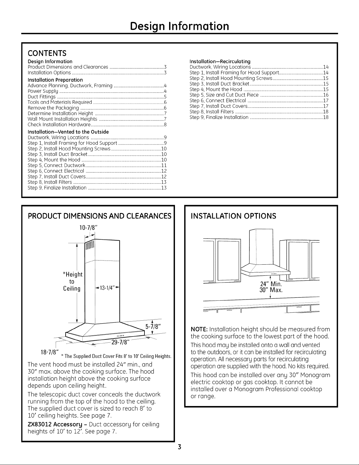
PRODUCT DIMENSIONS AND CLEARANCES
10-7/8"
t
:H ghte,.i:gii .13lJ,-1
18-7/8". TheSuppliedDuct CoverFits8'to 10'CeilingHeights.
The vent hood must be installed 2/4" min., and
:30" max. above the cooking surface. The hood
installation height above the cooking surface
depends upon ceiling height.
The telescopic duct cover conceals the ductwork
running from the top of the hood to the ceiling.
The supplied duct cover is sized to reach 8' to
10' ceiling heights. See page 7.
Z×83012 Accessorg - Duct accessorg for ceiling
heights of 10' to 12'. See page 7.
INSTALLATION OPTIONS
NOTE: Installation height should be measured from
the cooking surface to the lowest part of the hood.
This hood mag be installed onto a wall and vented
to the outdoors, or it can be installed for recirculating
operation. All necessarg parts for recirculating
operation are supplied with the hood. No kits required.
This hood can be installed over ang :30" Monogram
electric cooktop or gas cooktop. It cannot be
installed over a Monogram Professional cooktop
or range.
Page 4
Installation Preparation
ADVANCEPLANNING
• Determinethe exact location of the vent hood.
• Planthe route for venting exhaustto the outdoors.
• Usethe shortest and straightest duct route possible.For
satisfactory performance, duct run should not exceed 100 ft.
equivalent length for any duct configurations.
• Referto "Duct Fittings"chart on page 5to compute the
maximum permissiblelengthfor duct runsto the outdoors.
CAUTION:To reduce riskof fire and to properly
exhaust air,be sure to duct air outside-do not vent exhaust
air into spaceswithin walls or ceilingsor into attics, crawl
spacesor garages.
WARNING: TO REDUCE THE RISK OF FIRE,
USE ONLY METAL DUCTWORK.
• Installa wall cap with damper or roofcap at the exterior
opening.Orderthe wall or roof cap and any transition
neededin advance.
Wall Framing for Adequate Support
• Thisvent hood is heavy.Adequate structural support must
be provided in alltypes of installations.The hood must be
securedto vertical studs in the wall, orto a horizontal
support.
• The vent hood should be on sitebefore finalframing and
wall finishing.Thiswill help to accurately locatethe duct
work and electricalservice.
• Installation will be easierif the vent hood isinstalled before
the cooktop and countertop are installed.
ACCESSORYDUCT COVER
Thishood isshippedwith a decorative duct cover for ceiling
heights of 7'11" to 10'.TheZX83012duct cover accessory
isavailableto reachceiling heights between 10'1" and 12'.
Theaccessoryshould be ordered withthe hood and be
on sitebefore installation begins.
POWERSUPPLY
IMPORTANT- {Pleaseread carefullg)
WARNING:FORPERSONALSAFETY,
THISAPPLIANCEMUSTBEPROPERLYGROUNDED.
Removehouse fuse or open circuit breaker before beginning
installation.
Donot usean extension cord or adapter plug withthis
appliance. Follow National electricalcodes orprevailing local
codes and ordinances.
Electrical supplg
Thesevent hoods must be suppliedwith 120V,60Hz,and
connected to an individual,properly grounded branch circuit,
and protected by a 15 or 20 amp circuit breaker or time
delay fuse.
• Wiring must be 2 wire with ground.
• Ifthe electricalsupply doesnot meet the above
requirements,call a licensedelectrician before proceeding.
• Routehousewiring ascloseto the installation location as
possible,inthe ceiling or back wall. Referto Wiring Locations
on page 9.
• Connectthe hood wiring to the housewiring in accordance
with localcodes.
Grounding instructions
Thegrounding conductor must be connectedto a grounded
metal, permanent wiring system, or an equipment-grounding
terminal or leadon the hood.
WARNING:The improper connection of the
equipment-grounding conductor can resultin a risk of
electric shock.Checkwith a qualifiedelectrician or service
representative if you are in doubt whether the appliance is
properly grounded.
CAUTION:Automatically Operated Device-
Toreducethe risk of injury disconnect from power supply
before servicing.This unit isequipped with an integral
disconnecting switch located insidethe blower housing.
4
Page 5
Installation Preparation
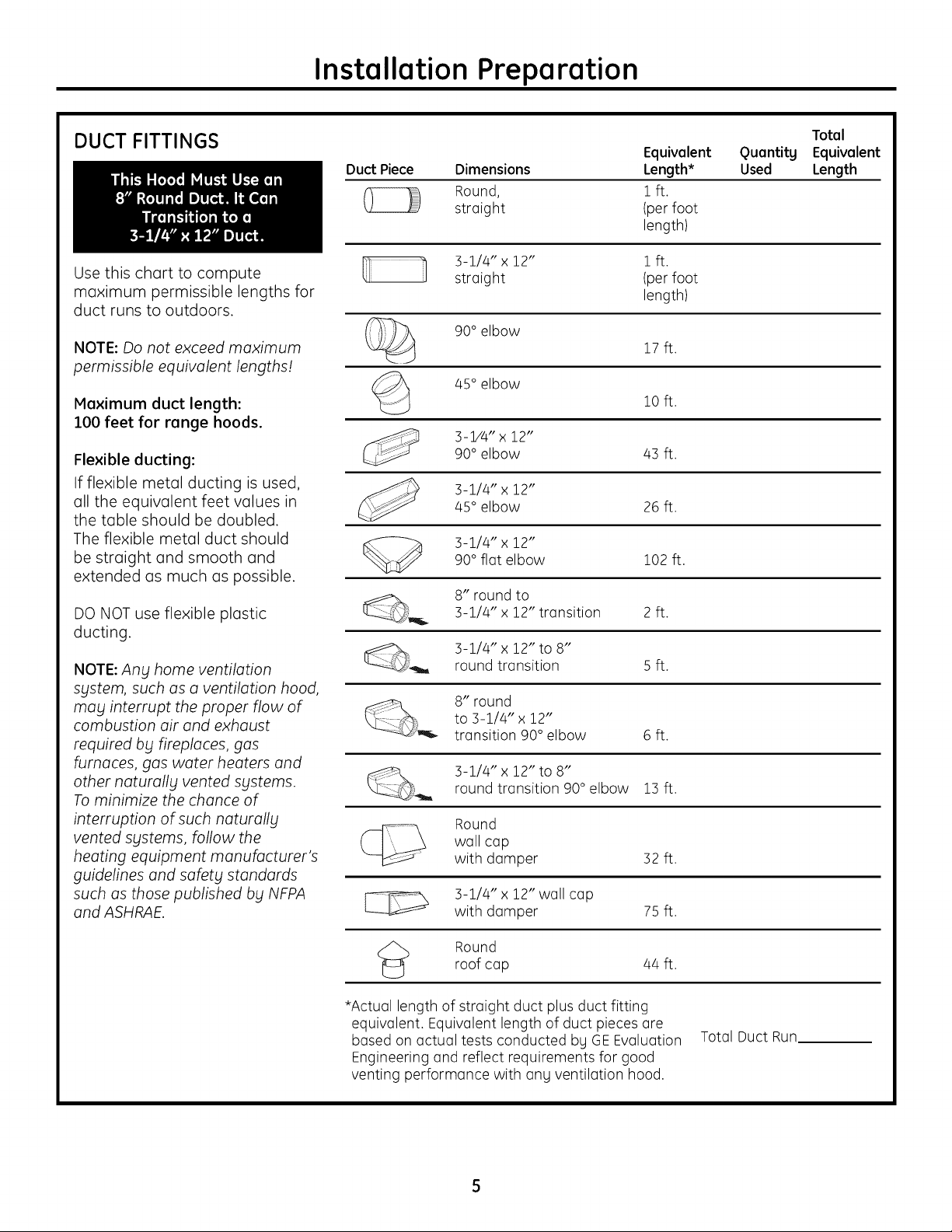
DUCT FITTINGS
Use this chart to compute
maximum permissible lengths for
duct runs to outdoors.
NOTE: Do not exceed maximum
permissible equivalent lengths!
Maximum duct length:
100 feet for range hoods.
Flexible ducting:
If flexible metal ducting is used,
all the equivalent feet values in
the table should be doubled.
The flexible metal duct should
be straight and smooth and
extended us much us possible.
Duct Piece Dimensions
Round,
straight
3-1/4" x 12" 1 ft.
straight (per foot
90° elbow
45° elbow
3-1/4" x 12"90° elbow 43 ft.
3-1/4" x 12"
45° elbow 26 ft.
90° flat elbow 102 ft.
3-1/4" x 12"
Equivalent
Length*
1ft.
(per foot
length)
length)
17 ft.
10 ft.
Quantity
Used
Total
Equivalent
Length
DO NOT use flexible plastic
ducting.
NOTE: Ang home ventilation
sgstem, such as a ventilation hood,
may interrupt the proper flow of
combustion air and exhaust
required by fireplaces, gas
furnaces, gas water heaters and
other naturallbl vented systems.
To minimize the chance of
interruption of such naturally
vented sgstems, follow the
heating equipment manufacturer's
guidelines and safety standards
such as those published bbl NFPA
and ASHRAE.
_,_ 8" round to3-1/4" x 12" transition 2 ft.
3-1/4" x 12" to 8"
round transition 5 ft.
8" round
to 3-1/4" x 12"
transition 90° elbow 6 ft.
3-1/4" x 12" to 8"round transition 90° elbow 13 ft.
Round
wall cap
with damper 32 ft.
F---_I----X 3-1/4" x 12" wall cap
L_x_
<_ Round
*Actual length of straight duct plus duct fitting
equivalent. Equivalent length of duct pieces are
based on actual tests conducted by GE Evaluation
Engineering and reflect requirements for good
venting performance with any ventilation hood.
with damper 75ft.
roof cap /4/4ft.
Total Duct Run
Page 6
Installation Preparation
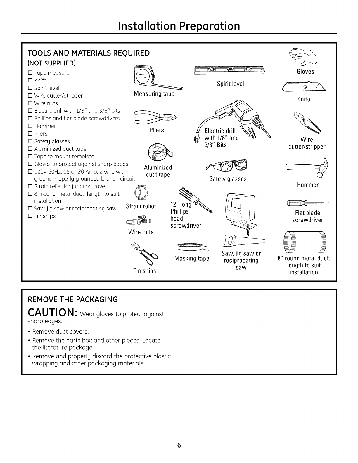
TOOLS AND MATERIALS REQUIRED
(NOT SUPPLIED)
[] Tape measure
[] Knife
[] Spirit level
[] Wire cutter/stripper
[] Wire nuts
[] Electric drill with 1/8" and 3/8" bits
[] Phillips and flat blade screwdrivers
[] Hammer
[] Pliers
[] Safetg glasses
[] Aluminized duct tape
[] Tape to mount template
[] Gloves to protect against sharp edges
[] 120V 60Hz. 15 or 20 Amp, 2 wire with
ground Properlg grounded branch circuit
[] Strain relief for junction cover
[] 8" round metal duct, length to suit
installation
[] Saw,jig saw or reciprocating saw
[] Tin snips
Measuring tape
Strain relief
Wire nuts
Pliers
Aluminized
ducttape
head
screwdriver
Spirit level
Electric drill
with 1/8" and
3/8" Bits
Safety glasses
Gloves
Knife
Wire
cutter/stripper
Hammer
Flat blade
screwdriver
Tin snips
REMOVE THE PACKAGING
CAUTION: Wear gloves to protect against
sharp edges.
• Remove duct covers.
• Remove the parts box and other pieces. Locate
the literature package.
• Remove and properlg discard the protective plastic
wrapping and other packaging materials.
Masking tape
Saw, jig saw or
reciprocating
saw
8" round metal duct,
length to suit
installation
Page 7
Installation Preparation
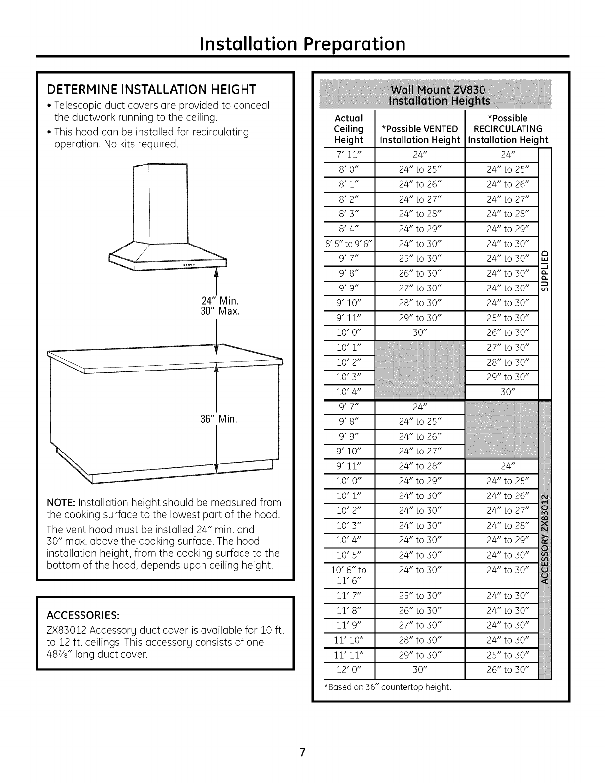
DETERMINE INSTALLATION HEIGHT
• Telescopic duct covers are provided to conceal
the ductwork running to the ceiling.
• This hood can be installed for recirculating
operation. No kits required.
24" Min.
30" Max.
36" Min.
NOTE: Installation height should be measured from
the cooking surface to the lowest part of the hood.
The vent hood must be installed 2/4" min. and
30" max. above the cooking surface. The hood
installation height, from the cooking surface to the
bottom of the hood, depends upon ceiling height.
ACCESSORIES:
ZX83012 Accessory duct cover is available for 10 ft.
to 12 ft. ceilings. This accessory consists of one
487/8" long duct cover.
Actual
Ceiling
Height
7'11"
8'0"
8'1"
8'2"
8'3"
8'4"
8' 5"to 9' 6"
9'7"
9'8"
9'9"
9' 10"
9'11"
10' O"
10' 1"
10'2"
i0'3"
10' 4"
9'7"
9'8"
9'9"
9' 10"
9'11"
10'0"
10' 1"
10'2"
i0'3"
10' 4"
10' 5"
10' 6"to
11'6"
11'7"
11'8"
11'9"
11' 10"
11' 11"
12'0"
*BQsed
on 36" countertop height.
*Possible VENTED
Installation Height
24"
24" to 25"
24" to 26"
24" to 27"
24" to 28"
24" to 29"
24" to 30"
25" to 30"
26" to 30"
27" to 30"
28" to 30"
29" to 30"
30"
24"
24" to 25"
24" to 26"
24" to 27"
24" to 28"
24" to 29"
24" to 30"
24" to 30"
24" to 30"
24" to 30"
24" to 30"
24" to 30"
25" to 30"
26" to 30"
27" to 30"
28" to 30"
29" to 30"
30"
24"
24" to 25"
24" to 26"
24" to 27"
24" to 28"
24" to 29"
24" to 30"
24" to 30"
24" to 30"
24" to 30"
24" to 30"
24" to 30"
25" to 30"
26" to 30"
Page 8
Installation Preparation
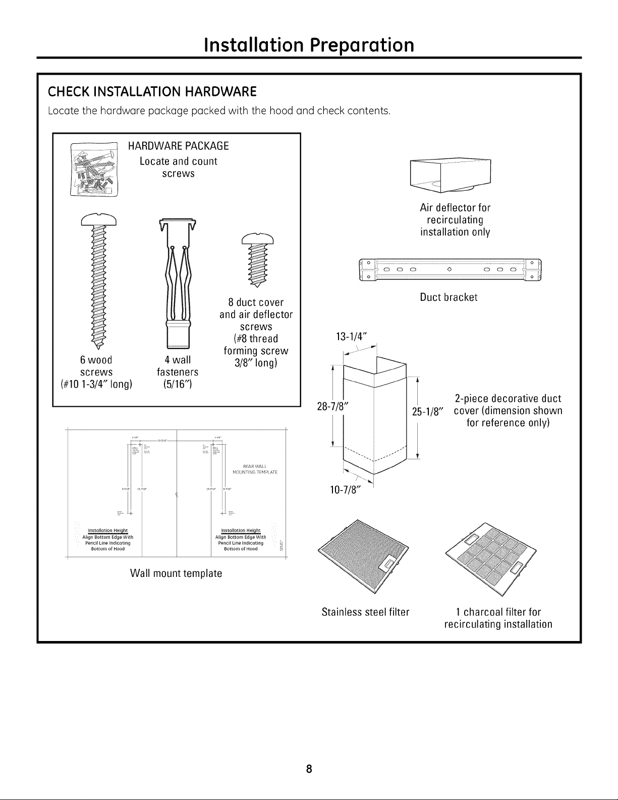
CHECK INSTALLATION HARDWARE
Locate the hardware package packed with the hood and check contents.
HARDWARE PACKAGE
Locate and count
screws
d
Air deflector for
recirculating
installation only
6wood
screws
(#10 1-3/4" long)
Installation Height
Align Bottom Edge With
Pencil Line Indicating
Bottom of Hood
4 wall
fasteners
(5/16")
Wall mount template
8 duct cover
and air deflector
screws
(#8 thread
forming screw
3/8" long)
REAR WALL
HOUNTING TEMPLATE
Installation Hei ht
Align Bottom Edge With
Pencil Line Indicating
Bottom of Hood
Duct bracket
13-1/4"
2-piece decorative duct
cover (dimension shown
for reference only)
Stainless steel filter 1 charcoal filter for
recirculating installation
Page 9
Installation Instructions
INSTALLATION--VENTED TO THE OUTSIDE
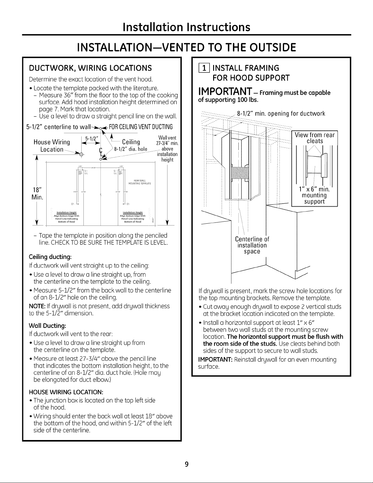
DUCTWORK, WIRING LOCATIONS
Determine the exact location of the vent hood.
• Locate the template packed with the literature.
- Measure 36" from the floor to the top of the cooking
surface. Add hood installation height determined on
page 7. Mark that location.
- Use a level to draw a straight pencil line on the wall.
5-1/2" centerline to wall--_- FORCEILINGVENTDUCTING
5-1/2" _j15-1/2" /_ Wallvent
House Wiring t.,_- \ L Ceiling 27-3/4"min
Locat on ,, _8-1/2" dla. hole ....above
yy
IVn.
AJlgnBottom EdgeWith
Pencillinelndlcotlng
- Tape the template in position along the penciled
line. CHECKTO BESURETHETEMPLATEIS LEVEL.
Ceiling ducting:
If ductwork will vent straight up to the ceiling:
• Use a level to draw a line straight up, from
the centerline on the template to the ceiling.
• Measure 5-1/2" from the buck wall to the centerline
of an 8-1/2" hole on the ceiling.
NOTE:If drywall is not present, add drywall thickness
to the 5-1/2" dimension.
Well Ducting:
If ductwork will vent to the rear:
• Use a level to draw a line straight up from
the centerline on the template.
• Measure at least 27-3/4" above the pencil line
that indicates the bottom installation height, to the
centerline of an 8-1/2" dia. duct hole. (Hole mag
be elongated for duct elbow.)
"_ ................. installation
Instellotlon He_qht
Bottom of Hood
Align Bottom edgeWith
PendJ Line Indlceting
Bottom of Hood
height
r
INSTALL FRAMING
FOR HOOD SUPPORT
IMPORTANT- Freming mustbecepeble
of supporting 100 Ibs.
8-1, min. opening for ductwork
View from rear
cleats
1" x 6" min.
mounting
support
Centerline of
installation
space
If drgwall is present, mark the screw hole locations for
the top mounting brackets. Remove the template.
• Cut awag enough drgwall to expose 2 vertical studs
at the bracket location indicated on the template.
• Install a horizontal support at least 1" x 6"
between two wall studs at the mounting screw
location. The horizontel support must be flush with
the room side of the studs. Use cleats behind both
sides of the support to secure to wall studs.
IMPORTANT: Reinstall drgwall for an even mounting
surface.
HOUSEWIRING LOCATION:
• Thejunction box is located on the top left side
of the hood.
• Wiring should enter the back wall at least 18" above
the bottom of the hood, and within 5-1/2" of the left
side of the centerline.
Page 10
Installation Instructions
INSTALLATION--VENTED TO THE OUTSIDE
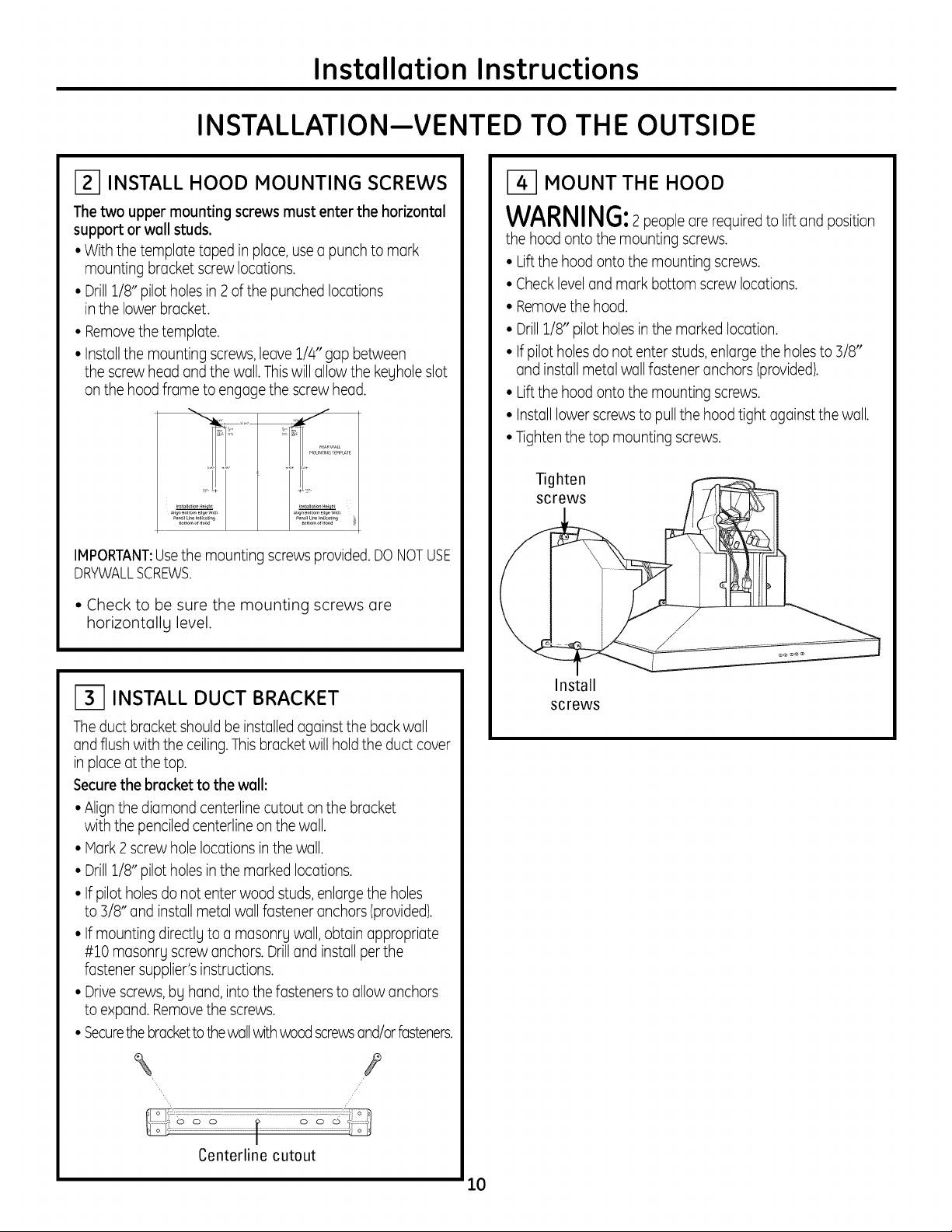
INSTALL HOOD MOUNTING SCREWS
Thetwo upper mounting screws must enter the horizontal
support or wall studs.
• With the template taped in place,usea punch to mark
mounting bracket screw locations.
• Drill1/8" pilot holes in 2 ofthe punched locations
in the lower bracket.
• Removethe template.
• Installthe mounting screws,leave 1/4" gap between
the screw head and the wall.Thiswill allow the kegholeslot
on the hood frame to engage the screw head.
IMPORTANT:Usethe mounting screws provided.DONOTUSE
DRYWALLSCREWS.
• Check to be sure the mounting screws ore
horizontallg level.
MOUNT THE HOOD
WARNING:2peopleare requiredto lift and position
the hood onto the mounting screws.
• Liftthe hood onto the mounting screws.
• Checklevel and mark bottom screw locations.
• Removethe hood.
• Drill1/8" pilot holesin the marked location.
• If pilot holesdo not enter studs,enlarge the holesto 3/8"
and install metal wallfastener anchors (provided).
• Liftthe hood onto the mounting screws.
• Installlower screwsto pullthe hood tight against the wall.
• Tighten the top mounting screws.
Tighten
screws
INSTALL DUCT BRACKET
Theduct bracket shouldbe installed againstthe back wall
and flush with the ceiling.This bracketwill holdthe duct cover
in place at the top.
Securethe bracket to the wall:
• Alignthe diamond centerline cutout on the bracket
with the penciled centerline on the wall.
• Hark 2 screwhole locations inthe wall.
• Drill1/8" pilot holes in the marked locations.
• If pilot holesdo not enter wood studs,enlargethe holes
to 3/8" and install metal wall fastener anchors (provided).
• If mounting directlg to a masonrg wall, obtain appropriate
#10 masonrL screw anchors.Drilland install perthe
fastener supplier's instructions.
• Drivescrews bg hand, into the fasteners to allow anchors
to expand. Removethe screws.
• Securethebracketto the wallwith woodscrewsand/orfasteners.
/
/
/"
Install
screws
Centerline cutout
10
Page 11
Installation Instructions
INSTALLATION--VENTED TO THE OUTSIDE
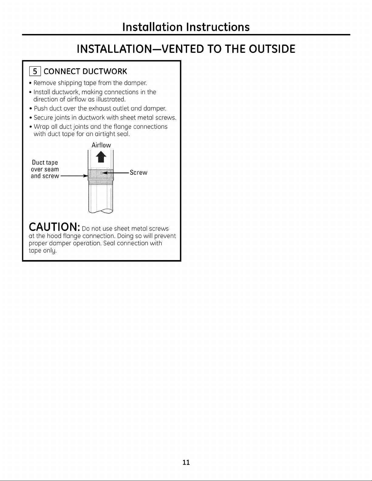
CONNECT DUCTWORK
• Remove shipping tape from the damper.
• Install ductwork, making connections in the
direction of airflow as illustrated.
• Push duct over the exhaust outlet and damper.
• Secure joints in ductwork with sheet metal screws.
• Wrap all duct joints and the flange connections
with duct tape for an airtight seal.
Airflow
Duct tape
over seam
and screw
_w
CAUTION: Do not use sheet metal screws
at the hood flange connection. Doing so will prevent
proper damper operation. Seal connection with
tape only.
11
Page 12
Installation Instructions
INSTALLATION--VENTED TO THE OUTSIDE
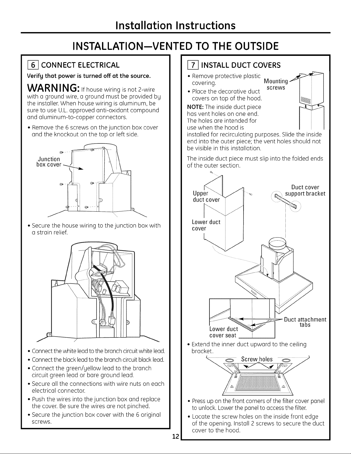
_-1 CONNECT ELECTRICAL
Verify that power is turned off at the source.
WARNING: if house wiring is not 2-wire
with a ground wire, a ground must be provided bLl
the installer. When house wiring is aluminum, be
sure to use U.L. approved anti-oxidant compound
and aluminum-to-copper connectors.
• Remove the 6 screws on the junction box cover
and the knockout on the top or left side.
Juncti°n _ _--"_
box cover-_ .l_
• Secure the house wiring to the junction box with
a strain relief.
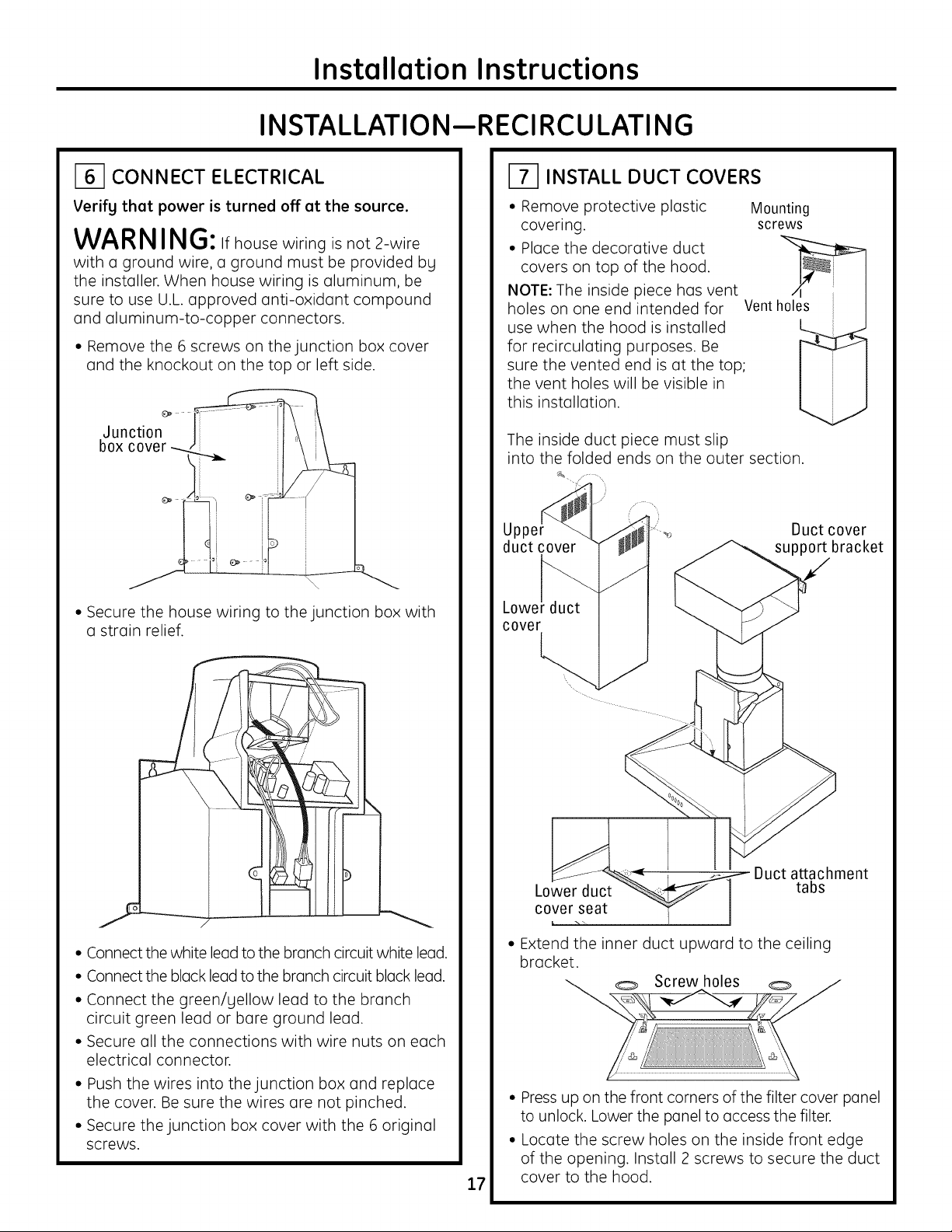
INSTALL DUCT COVERS
• Remove protective plastic
covering.
• Place the decorative duct
covers on top of the hood.
NOTE: The inside duct piece
has vent holes on one end.
The holes are intended for
use when the hood is
installed for recirculating purposes. Slide the inside
end into the outer piece; the vent holes should not
be visible in this installation.
The inside duct piece must slip into the folded ends
of the outer section.
¢&
Upper ....._
duct cover
Lower duct
cover
Mounting
screws
Duct cover
support bracket
• Connect the white lead to the branch circuit white lead.
• Connect the black lead to the branch circuit black lead.
• Connect the green/yellow lead to the branch
circuit green lead or bare ground lead.
• Secure all the connections with wire nuts on each
electrical connector.
• Push the wires into the junction box and replace
the cover. Be sure the wires are not pinched.
• Secure the junction box cover with the 6 original
screws.
Duct attachment
Lower duct
cover seat
• Extend the inner duct upward to the ceiling
bracket.
L-,. __.,.o .....Screw holes
• Press up on the front corners of the filter cover panel
to unlock. Lower the panel to access the filter.
• Locate the screw holes on the inside front edge
of the opening. Install 2 screws to secure the duct
cover to the hood.
12
tabs
Page 13
Installation Instructions
INSTALLATION--VENTED TO THE OUTSIDE
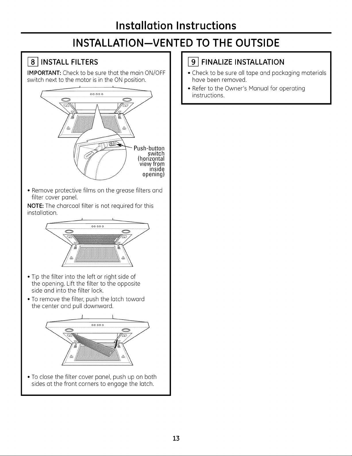
i81 INSTALL FILTERS
IMPORTANT: Check to be sure that the main ON/OFF
switch next to the motor is in the ON position.
Push-button
switch
(horizontal
view from
inside
opening)
• Remove protective films on the grease filters and
filter cover panel.
NOTE: The charcoal filter is not required for this
installation.
i91 FINALIZE INSTALLATION
• Check to be sure all tape and packaging materials
have been removed.
• Refer to the Owner's Manual for operating
instructions.
• Tip the filter into the left or right side of
the opening. Lift the filter to the opposite
side and into the filter lock.
• To remove the filter, push the latch toward
the center and pull downward.
I
• To close the filter cover panel, push up on both
sides at the front corners to engage the latch.
13
Page 14

Installation Instructions
INSTALLATI ON--R ECIRCULATING
DUCTWORK, WIRING LOCATIONS
• Determine the exact location of the vent hood.
• Locate the template packed with the literature.
• Measure 36" from the floor to the top of the cooking
surface. Add hood installation height determined on
page 7. Hark that location.
House Wiring _ _" Ceiling
Location- _
1 I"
n.
Instellotlon Helg_
AJlgn Bottom Edge With
PendJ Line Indi_tlng
Bottom of Hood
• Tape the template in position along the penciled line.
CHECKTOBE SURETHE TEMPLATEISLEVEL.
• Use a level to draw a line straight up, from
the centerline on the template to the ceiling.
Align Bottom FtJge With
Pencil Line Indlcoting
Bottom of Hood
INSTALL FRAMING
FOR HOOD SUPPORT
IMPORTANT: Freming must be capable
ofsupporting100 Ibs.
View from rear
cleats
1" x 6" rain.
mounting
support
Centerline of
installation
space
HOUSEWIRING LOCATION:
• Thejunction box is located on the top left side
of the hood.
• Wiring should enter the back wall at least 18"
above the bottom of the hood, and within 5-1/2"
of the centerline.
<..
If drgwall is present, mark the screw hole locations for
the top mounting brackets. Remove the template.
• Cut awag enough drgwall to expose 2 vertical studs
at the bracket location indicated on the template.
• Install a horizontal support at least 1" x 6"
between two wall studs at the mounting screw
location. The horizontel support must be flush with
the room side of the studs. Use cleats behind both
sides of the support to secure to wall studs.
IMPORTANT: Reinstall drywall for an even mounting
surface.
14
Page 15
Installation Instructions
INSTALLATI ON--R ECIRCULATING
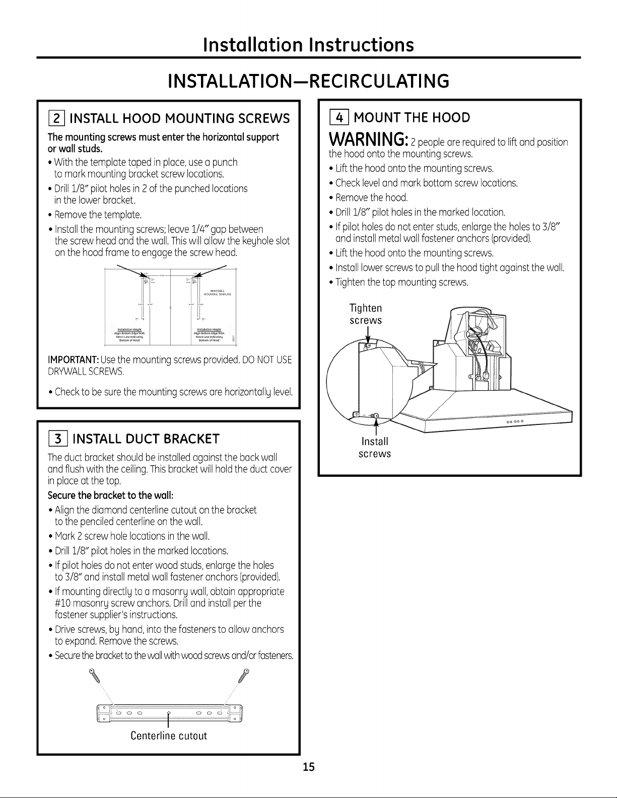
INSTALL HOOD MOUNTING SCREWS
The mounting screws must enter the horizontal support
or wall studs.
• With the template taped in place,usea punch
to mark mounting bracket screw locations.
• Drill1/8" pilot holesin 2of the punched locations
inthe lower bracket.
• Removethe template.
• Installthe mounting screws;leave 1/4" gap between
the screw head and the wall.Thiswill allow the kegholeslot
on the hood frame to engage the screw head.
f
BosomofHood
IMPORTANT:Usethe mounting screws provided.DONOTUSE
DRYWALLSCREWS.
• Checkto be surethe mounting screws are horizontallglevel.
MOUNT THE HOOD
WARNING:2people are requiredto lift and position
the hood onto the mounting screws.
• Liftthe hood onto the mounting screws.
• Checklevel and mark bottom screw locations.
• Removethe hood.
• Drill1/8" pilot holesin the marked location.
• If pilot holesdo not enter studs, enlargethe holesto 3/8"
and install metal wall fastener anchors (provided).
• Liftthe hood onto the mounting screws.
• Installlower screwsto pull the hood tight against the wall.
• Tighten the top mounting screws.
Tighten
screws
INSTALL DUCT BRACKET
Theduct bracket shouldbe installed againstthe back wall
and flush with the ceiling.This bracketwill holdthe duct cover
in place at the top.
Securethe bracket to the wall:
• Alignthe diamond centerline cutout on the bracket
to the penciledcenterline onthe wall.
• Hark 2 screwhole locations inthe wall.
• Drill1/8" pilot holes in the marked locations.
• If pilot holesdo not enter wood studs,enlargethe holes
to 3/8" and install metal wall fastener anchors (provided).
• If mounting directlg to a masonrg wall, obtain appropriate
#10 masonrL screw anchors.Drilland install perthe
fastener supplier's instructions.
• Drivescrews bg hand, into the fasteners to allow anchors
to expand. Removethe screws.
• Securethebracketto the wallwith woodscrewsand/orfasteners.
\ Y
/
/
Install
screws
Centerline cutout
15
Page 16
INSTALLATI ON--R ECIRCULATING
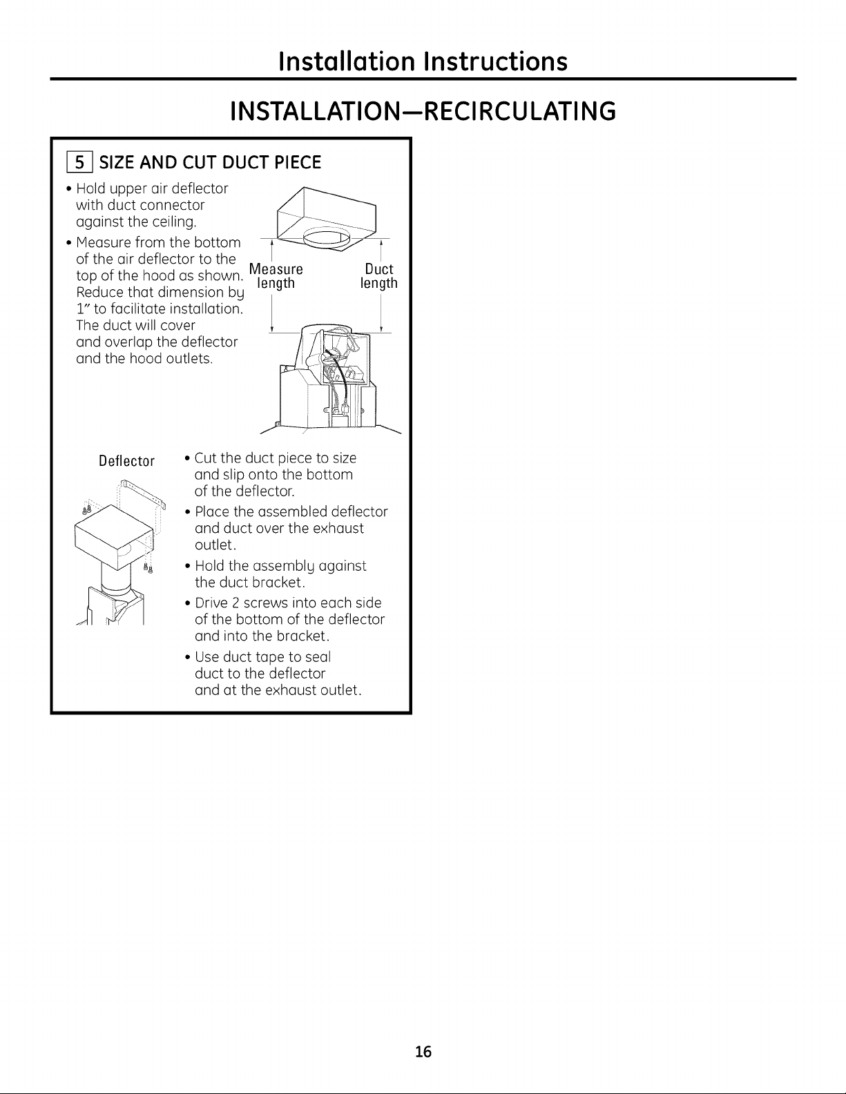
SIZE AND CUT DUCT PIECE
• Hold upper air deflector
with duct connector
against the ceiling.
• Measure from the bottom
of the air deflector to the
top of the hood as shown. Measure
educethat dimension by length
to facilitate installation.
The duct will cover
and overlap the deflector
and the hood outlets.
Installation Instructions
Duct
length
Deflector
• Cut the duct piece to size
and slip onto the bottom
of the deflector.
• Place the assembled deflector
and duct over the exhaust
outlet.
• Hold the assembly against
the duct bracket.
• Drive 2 screws into each side
of the bottom of the deflector
and into the bracket.
• Use duct tape to seal
duct to the deflector
and at the exhaust outlet.
16
Page 17
Installation Instructions
INSTALLATI ON--R ECIRCULATING
_-1 CONNECT ELECTRICAL
Verify that power is turned off at the source.
WARNING: ifhouse wiring is not 2-wire
with a ground wire, a ground must be provided bLl
the installer. When house wiring is aluminum, be
sure to use U.L. approved anti-oxidant compound
and aluminum-to-copper connectors.
• Remove the 6 screws on the junction box cover
and the knockout on the top or left side.
Junction _"
box cover_ I \ _\
• Secure the house wiring to the junction box with
a strain relief.
INSTALL DUCT COVERS
• Remove protective plastic
covering.
• Place the decorative duct
covers on top of the hood.
NOTE: The inside piece has vent
holes on one end intended for
use when the hood is installed
for recirculating purposes. Be
sure the vented end is at the top;
the vent holes will be visible in
this installation.
The inside duct piece must slip
into the folded ends on the outer section.
J
Up_
duct cover
Lowe!
cover
...._ Duct cover
Mounting
screws
Vent holes
support bracket
• Connect the white lead to the branch circuit white lead.
• Connect the black lead to the branch circuit black lead.
• Connect the green/yellow lead to the branch
circuit green lead or bare ground lead.
• Secure all the connections with wire nuts on each
electrical connector.
• Push the wires into the junction box and replace
the cover. Be sure the wires are not pinched.
• Secure the junction box cover with the 6 original
screws.
Duct attachment
Lower duct
cover seat
• Extend the inner duct upward to the ceiling
bracket.
'-__...._.o Screw holes
• Press up on the front corners of the filter cover panel
to unlock. Lower the panel to access the filter.
• Locate the screw holes on the inside front edge
of the opening. Install 2 screws to secure the duct
17
cover to the hood.
tabs
Page 18
Installation Instructions
INSTALLATI0 N--R ECIRCULATING
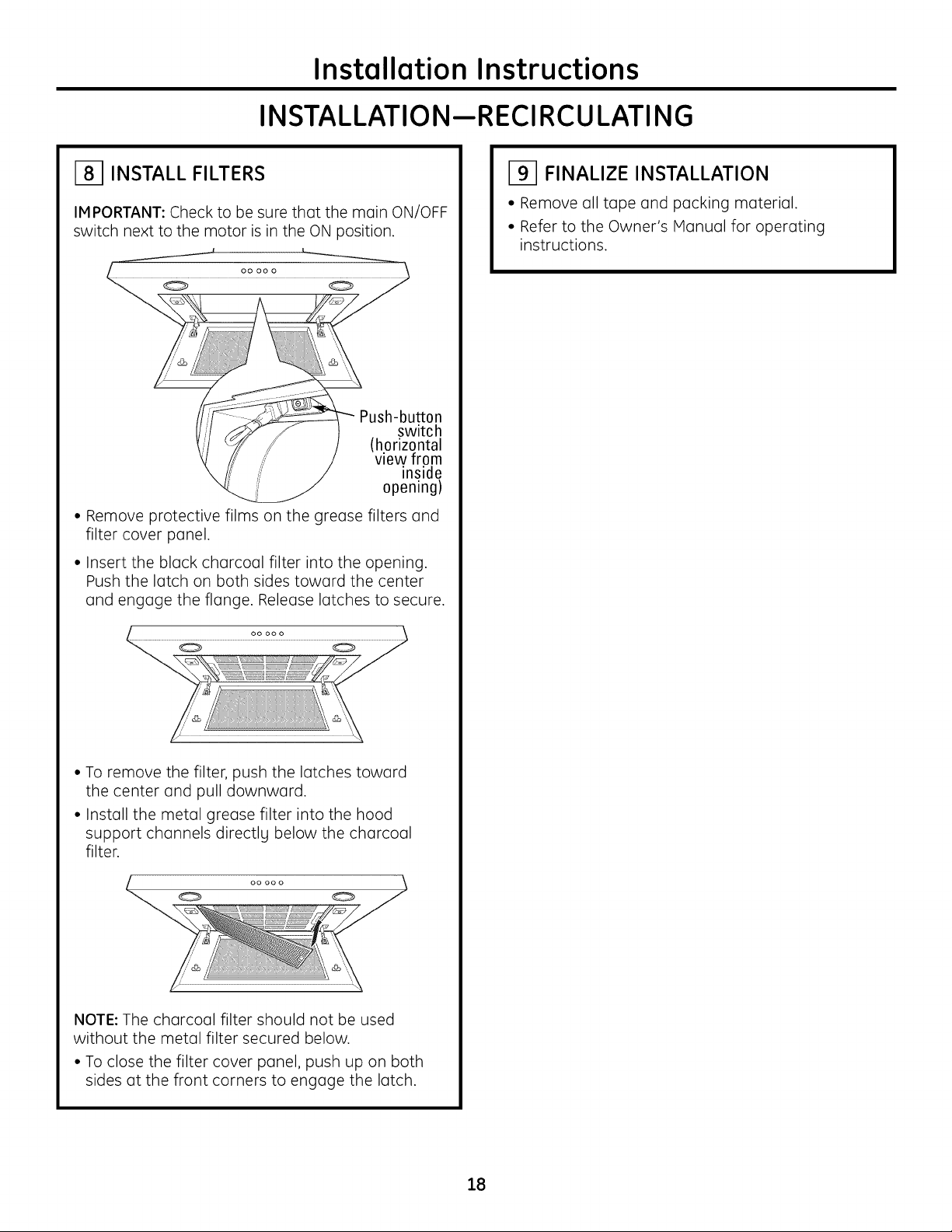
i81 INSTALL FILTERS
IMPORTANT: Check to be sure that the main ON/OFF
switch next to the motor is in the ON position.
Push-button
switch
(horizontal
view from
inside
opening)
• Remove protective films on the grease filters and
filter cover panel.
• Insert the black charcoal filter into the opening.
Push the latch on both sides toward the center
and engage the flange. Release latches to secure.
i91 FINALIZE INSTALLATION
• Remove all tape and packing material.
• Refer to the Owner's Manual for operating
instructions.
0 0
• To remove the filter, push the latches toward
the center and pull downward.
• Install the metal grease filter into the hood
support channels directlg below the charcoal
filter.
0
NOTE: The charcoal filter should not be used
without the metal filter secured below.
• To close the filter cover panel, push up on both
sides at the front corners to engage the latch.
18
Page 19

Installation Instructions
NOTES
19
Page 20

Installation Instructions
NOTES
20
Page 21

Consignes de s curit
LISEZ ET CONSERVEZ CES INSTRUCTIONS
AVANT DE COMMENCER
Veuillez lire attentivement ces instructions dans leur
int_gralit_.
•IMPORTANT- Veuillezconserver
ces instructions pour afin que I'inspecteur local
puisse s'g r_f_rer.
• IMPORTANT- Respectez tousles codes
r_glementaires et les r_glements.
• Note destin_e 6 I'installateur - Assurez-vous
de laisser ces instructions au client.
• Note destin_e au client - Veuillez conserver
ces instructions avec votre manuel utilisateur afin
de pouvoir vous g r_f_rer ult_rieurement.
• Niveau de competence -I'installation de cet
appareil requiert des comp_tences en mati_re de
m_canique et d'_lectricit&
• Dur6e d'assemblage - 1 6 3 heures.
• L'installation incombe 6 I'installateur. Sile produit
connaTt une d_faillance due 6 une installation
inappropri_e, la garantie ne s'applique pas.
Pour leservicede Monogram au Canada,
appelezle 1.800.561.3344.
Pour lespi_ceset accessoiresde Monogram,
appelezle 1.800.561.3344.
ATTENTION:
A cause du poids et de la taille de ces hottes
et pour reduire le risque de blessures et de dommages,
IL FAUTDEUX PERSONNESPOURFAIREL'INSTALLATION
CORRECTEMENT.
AVERTISSEMENT :
Pour r_duire le risque d'incendie ou de choc _lectrique,
il ne faut pas utiliser cette hotte avec un r_gulateur
de vitesse _lectronique externe. Toute modification
de ce tgpe du branchement d'usine peute endommager
I'appareil ou crier un risque de choc _lectrique.
AFIN DE RI_DUIRELERISQUED'INCENDIE, N'UTILISEZ
QUE DESCONDUITS MI'--TALLIQUES.
AVERTISSEMENT:POURRI_DUIRE
LERISQUED'INCENDIE,DECHOCI'-_-LECTRIQUEOU DE
BLESSURES,ILFAUTOBSERVERLESREGLESSUIVANTES:
A. Utilisez cet appareil uniquement de Io mani_re
pr_vue par le fabricant. En cas de question, consultez
le fabricant.
Bo
Avant toute intervention ou nettogage, coupez
I'alimentation _lectrique au disjoncteur et verrouillez
le panneau du disjoncteur pour _viter la mise sous
tension accidentelle. S'il n'est pas possible de
verrouiller lepanneau du disconcteur, attachez
un placard ou une _tiquette tr_s visible au panneau.
ATTENTION : UNIQUEMENT ADES FINS
DE VENTILATION. NE L'UTILISEZ PAS POUR I_VACUER
DES SUBSTANCES DANGEREUSES, DES MAT#RIAU×
EXPLOSIFS OU DES VAPEURS.
AVERTISSEMENT: AFIN DE RI_DUIRE
LE RISQUE D'INCENDIE, LES I_LECTROCUTIONS OU
LES BLESSURES AU× PERSONNES, VEUlLLEZ RESPECTER
CE QUI SUIT :
• L'installation et le c6blage _lectrique doivent
_tre effectu_s par des personne(s) qualifi_e(s)
conform_ment aux r_glements et normes applicables,
dont ceux relatifs 6 la construction ignifuge.
• Une quontit6 suffisante d'oir est n_cessaire pour
la combustion et I'_vacuation des gaz via le carneau
(hotte) de I'_quipement 6 carburant afin d'_viter
une contre-explosion. Veuillez suivre les consignes
du fabricant de I'appareil de chauffage et les normes
de s_curit_, telles que celles publi_es par I'Association
nationale de protection anti-incendie (NFPA),
I'association am_ricaine des ing_nieurs du chauffage,
de la r_frig_ration et de la climatisation (ASHRAE)
ainsi que les autorit_s locales.
• Lorsque vous coupez ou percez des murs ou des
plafonds, veillez 6 ne pas endommager les c6bles
_lectriques et autres applications cach_es par lemur.
• Les sgst_mes de conduits doivent toujours _tre
ventil_s vers I'ext6rieur.
Les r_glements Iocoux sont susceptibles de varier.
L'installation de raccords _lectriques et de mise
6 la terre doivent _tre conformes aux r_glementations
applicables. EnI'absence de r_glements, I'_vent doit
_tre install_ conform_ment au code _lectrique national
ANSI/NFPA70-1990 ou version plus r_cente.
ATTENTION :,lfaut prendre soin d'installer
un conduit vers I'ext_rieur pour r_duire le risque
d'incendie et pouvoir _vacuer I'air correctement.
IIne faut pas _vacuer I'air dans I'espace entre les parois
d'un mur, un plafond ou un grenier, un espace sanitaire
ou un garage.
21
Page 22

Consignes de conception
TABLE DES MATII_RES
Consignes de conception
Dimensions et intervalles ..........................................................................22
Options d'installation ................................................................................22
Preparation _ I'installation
Planification, canalisations, encadrement ......................................23
Alimentation ....................................................................................................23
Raccords de canalisation ........................................................................24
Outils et mat_riaux n_cessaires ..........................................................25
Retirer I'emballage ......................................................................................25
D_finition de la hauteur d'installation ................................................26
Hauteurs d'installation sur le mur ........................................................26
V_rification du materiel d'installation ................................................27
Installation--Ventil_ vers I'ext_rieur
Emplacement des canalisations et des c6bles ..............................28
Etape 1, Installer I'encadrement pour la fixation de la hotte..28
Etape 2, Installer les vis d'assemblage de la hotte ......................29
Etape 3, Installer le support de canalisation ..................................29
Etape/4, Monter la hotte ..........................................................................29
Etape 5, Connecter la canalisation ......................................................30
Etape 6, Connecter les parties _lectriques ......................................31
Etape 7, Installer les caches de conduit ............................................31
Etape 8, Installer les filtres ......................................................................32
Etape 9,Terminer I'installation ..............................................................32
Installation--Recgclage
Emplacement des canalisations et des c6bles ..............................33
Etape 1, Installer I'encadrement pour la fixation de la hotte..33
Etape 2, Installer les vis d'assemblage de la hotte ......................34
Etape 3, Installer le support de canalisation ..................................34
Etape/4, Monter la hotte ..........................................................................38
Etape 5, Mesurer et couper le conduit ..............................................35
Etape 6, Connecter les parties _lectriques ......................................36
Etape 7, Installer les caches de conduit ............................................36
Etape 8, Installer les filtres ........................................................................37
Etape 9,Terminer I'installation ..............................................................37
DIMENSIONS ET INTERVALLES
28 cm (10-7/8 p0)
*Hauteur i 34cm
-----I- pal
47 Cm (18-7/8 po) *Lecache conduitfoumiconvientaux hauteurs
La hotte d'aspiration doit _tre install_e
(_au mains 60 cm (24 po), et 76 cm (:30po)
au-dessus de la surface de cuisson. La hauteur
d'installation de la hotte au-dessus de la surface
de cuisson d_pend de la hauteur de plafond.
Le couvercle t_lescopique dissimule les conduits
partant du haut de la hotte jusqu'au plafond.
Le cache fourni s'adapte aux hauteurs de plafond
de 2,4 m (_:3,l m (8 pi (_10 pi). Consultez page 26.
Accessoire ZX8:3012 - Un accessoire pour conduit
pour hauteurs de plafond de :3,l m (_ :3,7m
(10 pi (_ 12 pi). Consultez page 26.
de pldonds de 2,4m _ 3,1m (8 pi_ 10 pi)
OPTIONS D'INSTALLATION
o_
61 cm (24 p0) Min
76,2cm (30_P£0_)Max
NOTE : La hauteur d'installation doit _tre mesur_e
(_partir de la surface de caisson (_la partie la plus
basse de la hotte.
Cette hotte doit _tre install_e sur un mur et ventil_e
vers I'ext_rieur, ou elle peut _tre install_e pour
I'op_ration de recgclage. Toutes les parties
n_cessaires (_I'op_ration de recgclage sont
fournies avec la hotte. Aucun kit n'est n_cessaire.
Cette hotte peut _tre install_e sur une table
de cuisson Monogram de 76,2 cm (:30po) ou
une cuisini_re (_gaz. Elle ne peut _tre install_e
sur une table de cuisson ou une cuisini_re
professionnelle Monogram.
22
Page 23

Preparation 6 l'installation
PLANIFICATION
• D@terminezI'emplacementde la hotte aspirante.
• Planifiezle parcoursdu conduit d'@chappementvers
I'ext@rieur.
• Faitesen sorte que le parcourssoit le pluscourt et le plus
droit possible.Pourdesperformances optimales, le parcours
du conduit ne dolt pas d@passer3 m (100pi)de Iongueur
@quivalentepour desconfigurations de conduit.
• Reportez-vousau tableau Raccordsde conduit figurant sur
la page 2/4pour calculerla Iongueur maximale acceptable
pour lesparcours de conduit vers I'ext@rieur.
ATTENTION:llfautprendresoind'installer
un conduit vers I'ext6rieur pourr@duirele risqued'incendie
et pouvoir @vacuerI'aircorrectement. IIne faut pas @vacuer
I'airdansI'espaceentre lesparoisd'un mur,un plafond ou
un grenier,un espacesanitaire ou un garage.
AVERTISSEMENT: AFIN DE RI_DUIRE
LE,RISQ)UE D'INCENDIE, N'UTILISEZ Q)UE DES CONDUITS
METALLIQ)UES.
• Installezune protection murale avec registreou une
protection de toiture sur I'ouverture ext@rieureCommandez
la protection de toiture ou murale et tout raccord 6 I'avance.
Support mural pour une fixation adequate
• Cettehotte aspirante est Iourde.Unesupport de structure
ad@quatdolt @trefourni surtousles tupes d'installation.
La hotte dolt @trefix@esur des chevillesverticales dans
lemur, ou sur un support horizontal.
• La hotte aspirante dolt setrouver sur le siteavant
I'encadrementfinal et la finition murale. Cecipermettra
de rep@rerlesconduits et lecompartiment @lectrique.
• L'installationsera plusfacile si la hotte est install@e
avant latable de cuisson et le plande travail.
ACCESSOIRECACHECONDUIT
Cettehotte est dot_e d'un cache conduit d#coratif pour
deshauteurs de plafondsde 2,206 2,40m (7pi 11 po6 10 pi).
Lecache conduit ZX83012 estdisponiblepour atteindre
leshauteurs de plafonds de 3 m 6 3,40m (10 pi I po 6 12 pi).
L'accessoiredolt #tre command# avec la hotte etsetrouver
sur lesite avant de proc#der 6 I'installation.
ALIMENTATION
IMPORTANT- (Alire attentivement)
AVERTISSEMENT:POURDESRAISONSDE
SI_CURITI_,CETAPPAREILDOlT/:TRECORRECTEMENT
MISALATERRE.
Retirezlefusible de votre domicile ou ouvrez ledisjoncteur
avant de proc#der 6 I'installation.
N'utilisezpasde cordon de rallonge ou de priseadaptateur
avec cet appareil.Veuillezsuivreles codes @lectriques
nationaux ou lescodes Iocauxet lesr@glementations.
Alimentation _lectrique
Ceshottesaspirantes doivent @treutilis@esavec du courant de
tupe 120V,60 Hzetconnect@es6 un circuit correctement mis
6 laterre et prot@g@espar un disjoncteur de tupe 15ou 20
Amp ou un fusible de surcharge.
• Leraccordement dolt @treassur@par deux 2 c6bles mise
6 la terre.
• SiI'alimentation @lectriquene r@pondpas auxexigences
ci-dessus,appelez un @lectricienagr@@avant de continuer.
• Placezlesc6bles 6 proximit@deI'emplacement de
I'installationdans le plafond ou lemur arri@re.Reportez-vous
aux emplacements des c6bles de la page 28.
• Connectezlesc6bles dela hotte au domicile conform@ment
aux codesIocau×.
Consignesrelatives6 la mise6laterm
Leconducteur de terre dolt #tre connect# 6 un syst_me
m#tallique permanent de c6bles raccord#s6 laterre ou
6 une borne de mise 6 laterre ou au cOblede la hotte.
AVERTISSEMENT:Lemauvaisbranchementdu
fil de mise 6 la terre peut causer un choc @lectrique.Encas de
doute, consultez un @lectricienqualifi@ou un technicien pour
d@terminersiI'appareilest 6 laterre.
ATTENTION:Appareilcommand@
automatiquement. Afin de r@duirelesrisquesde blessure,
d@branchezI'appareilde I'alimentation @lectriqueavant
de proc@der_une r@paration.L'appareilest @quip@
d'un sectionneur int@gralsitu@6 I'int@rieurdu Iogement
du ventilateur.
23
Page 24

Preparation 6 l'installation
RACCORDS DE
CANALISATION
Reportez-vous au tableau pour
calculer les Iongueurs maximales
autoris6es pour les conduits vers
I'ext6rieur.
REMAROUE : Ne d#passez pas les
Iongueurs maximales autoris#es /
Longueur maximale de conduit :
30 m (100 pi) pour les hottes
de cuisiniare.
Conduit flexible :
En cas d'utilisation de conduits
m6talliques flexibles, les valeurs
en pieds figurant dans le tableau
doivent _tre doubl6es. Le conduit
m6tallique flexible doit _tre droit
et lisse et 6tir6 au maximum.
N'utilisez PAS de conduit
en plastique flexible.
REMAROUE : Tout syst_me
de ventilation domestique tel
qu'une hotte ospironte, est
susceptible d'interrompre le d@bit
d'oir et de fum@es de combustion
requis pour les chemin@es, fours
6 gaz, les chauffe-eou 6 gaz et
autres syst_mes naturellement
ventil@s.Afin de r@duire
les probabilit_s d'interruption
de ces syst_mes naturellement
ventil@s,nous vous
recommandons de suivre
les consignes du fabricant
de I'@quipement de chauffage
et les normes de s4curit4 telles
que celles publi@es par la NFPA
et I'ASHRAE.
Conduit Dimensions
Randdroit
Oroit 8 cm x 30 cm
(3-1/4 pox 12 po)
Coude 90°
Coude 45°
Coude 90° 8 cm x 30 cm
(3-J/4 pox 12 po)
Coude 45° 8 cm x 30 cm
(3-1/4 pox 12 po) 7,90 m (26 pieds)
Coudeplat9008cmx30cm
(3-1/4 po x 12 po) 32 m (102 pieds)
Rand20cm(8po)pourraccord
8 cm x30cm(3-1/4pox 12po) 60 cm (2 pieds)
8 cmx30cm (3-1/4pox 12po)
pourraccordrand20cm (8po) 1,5 m (5 pieds)
Rand20cm(8po)pourraccord
encoude9008cmx 30cm
(3-1/4pox 12po) 1,8 m (6 pieds)
8 cm x 30 cm (3-1/4 po x 12 po)
pour raccord rand 20cm
(8po)en coude 90° 3,96 m (13 pieds)
mur rand
Cache
avec registre 9,7 m (52 pieds)
Cache mur 9 cm x 30 cm
(3-1/4 pox 12 po)
avec registre 22,9 m (75 pieds)
Cache rand
pour toiture 13 m (44 pieds)
*Longueur r_elle du conduit droit plus le raccord
de conduit 6quivalent. Longueur 6quivalente des
conduits bas6e sur les tests par les ing6nieurs
GEet satisfaisant aux exigences pour de bonnes
performances en termes de ventilation de toute
hotte aspirante.
Longueur
_quivalente*
30 cm (1 pied)
(par Iongueur
en pied)
30 cm (1 pied)
(par Iongueur
en pied)
5 m (17 pieds)
3 m (10 pieds)
13 m (43 pieds)
Quantit_
utilis_e
Parcours total
des conduits
Longueur
total
_quivalente
24
Page 25

Preparation 6 l'installation
OUTILS ET MATI_RIAUX NI_CESSAIRES
(NON FOURNIS)
[] M_tre ruban
[] Couteau
[] Niveau _ bulle d'air
[] Coupe-fils/outil _ d_nuder les ills
[] Serre-fils
[] Perceuse _lectrique avec forets
3,2 mm et 9,5 mm (1/8 pc et 3/8 pc)
[] Tournevis cruciforme et tournevis
t_te plate
[]Harteau
[] Pinces
[] Lunettes de protection
[] Ruban aluminis_
[] Ruban pour monter le gabarit Ruban
[] Gants pour prot6ger contre
[] 2 cables 120 V 60 Hz. 15 ou 20 Amp
avec circuit correctement
mis @la terre
les lames tranchantes _ m__17%
[] R_ducteur de tension pour
couvercle de connexion
[] Conduit m@talliquerond 20 cm
(8 pc), Iongueur conforme
I'installation
[] Scie, scie sauteuse
ou scie alternative
[] Cisailles @@tain
M_tre _ ruban
Pinces
aluminise
Beducteur de tension
30 c
Tourneviscruciforme
Serre-fils
_'_ Ruban-cache
Cisailles etain
Niveau _ bulb d'air
Perceuse
electrique avec
forets 3,2 mm et 9,5 mm
(1/8 pc et 3/8 pc)
Lunettesde protection
Scie, scie sauteuse
ou scie alternative
%
Gants
Couteau
Coupe-ills/
Outil _ denuder
Marteau
Tournevis_ t@te
plate
Conduit metallique rond
de 20 cm (8 pc) conforme
I'installation.
RETIRER L'EMBALLAGE
ATTENTION : Veillez (_porter des gants
afin de vous prot@ger contre les lames tranchantes.
• Retirez les caches conduit.
• Retirez la boTte de pi_ces et autres pi_ces.
Consultez le manuel utilisateur.
• Retirez et jetez les emballages plastiques de
protection et autres mat#riaux d'emballage.
25
Page 26

Preparation 6 l'installation
DI_FINITION DE LA HAUTEUR
D'INSTALLATION
• Les caches conduit t_lescopiques servent
(_dissimuler les conduits allantjusqu'au plafond.
• Cette hotte peut #tre install#e pour I'op#ration
de recyclage. Aucun kit n'est n#cessaire.
61 cm (24 po) Min.
76,2 cm (30 po) Max.
91,4 cm (36 po) Min.
REMARQUE : La hauteur d'installation doit _tre
mesur6e (_partir de la surface de caisson (_la partie
la plus basse de la hotte.
La hotte d'aspiration doit _tre install6e
(_au mains 60 cm et 76 cm (24 poet 30 po)
au-dessus de la surface de cuisson. La hauteur
d'installation de la hotte au-dessus de la surface
de cuisson d6pend de la hauteur de plafond.
ACCESSOIRES :
La cache conduit ZX83012 est disponible pour les
plafonds de :3m (_:3,60 m (10 pi (_ 12 pi). II s'agit d'un
cache conduit d'une Iongueur de 122 cm (487/8po).
Hauteur de
plafond
r_elle
7 pi 11 po
8 pi 0 po
8 pi 1 po
8 pi 2 po
8 pi 3 po
8 pi 4 po
8 pi 5 po
(_9 pi6po
9 pi 7 po
9 pi 8 po
9 pi 9 po
9 pi 10 po
9 pi 11 po
10 pi 0 po
10 pi 1 po
10 pi 2 po
10 pi 3 po
10 pi 4 po
9 pi 7 po
9 pi 8 po
9 pi 9 po
9 pi 10 po
9 pi 11 po
10 pi 0 po
10 pi 1 po
10 pi 2 po
10 pi 3 po
10 pi 4 po
10 pi 5 po
10 pi 6 po (_
11 pi 6 po
11 pi 7 po
11 pi 8 po
11 pi 9 po
11 pi 10 po
11 pi 11 po
12 pi 0 po
*BQs_surIQ
Hauteur
Hauteurd'installation
VENTILI_E*
24 po
24 po _ 25 po
24po(_26po
24po(_27po
24po(_28po
24po(_29po
24 po a 30 po 24 po a 30 po
25 po a 30 po 24 po a 30 po
26 po a 30 po 24 po a 30 po
27 po a 30 po 24 po a 30 po
28 po a 30 po 24 po a 30 po
29 po a 30 po 25 po a 30 po
30 po 26 po a 30 po
24 po
24 po a 25 po
24 po a 26 po
24 po a 27 po
24 po a 28 po 24 po
24 po a 29 po 24 po a 25 po
24 po a 30 po 24 po a 26 po
24 po a 30 po 24 po a 27 po
24 po a 30 po 24 po a 28 po
24 po a 30 po 24 po a 29 po
24 po a 30 po 24 po a 30 po
24 po a 30 po 24 po a 30 po
25 po a 30 po 24 po a 30 po
26 po a 30 po 24 po a 30 po
27 po a 30 po 24 po a 30 po
28 po a 30 po 24 po a 30 po
29 po a 30 po 25 po a 30 po
30 po 26 po a 30 po
hQuteurdu plQnde trQvQilde 91 cm (36po).
d'installation
de RECYCLAGE*
24 po
24 po _ 25 po
24 po _ 26 po
24 po _ 27 po
24 po _ 28 po
24 po (_29 po
28 po _ 30 po
29 po (] 30 po
30 po
26
Page 27

Preparation 6 l'installation
VF!RIFICATION DU MATF!RIEL D'INSTALLATION
Inspectez le paquet de I'appareil emball_ avec la hotte et v_rifiez le contenu.
................. EMBALLAGEDUMAT%IEL
Reperezet comptez les vis
d
Collecteur d'air pour
installation de
recyclage uniquement
6 vis _ bois (#10
45 mm [1-3/4 pc]
de Iongueur)
Installation Height
Align Bottom Edge With
Pencil Line Indicating
Bottom of Hood
4 chevilles
murales
(79 mm [5/16 pc])
Align Bottom Edge With
Calibrede support mural
8 vis de couvercle
de conduit et de
ddlecteur d'air
(vis #8 de 95 mm
[3/8 pc] long
formant un filete)
REAR WALL
MOUNTING TEMPLATE
Installation Hei ht
Pencil Line Indicating
Bottom of Hood
33,7 cm
(13-1/4 pc)
73,3 cm
(28-7/8 pc)
27,6 cm
(10-7/8 pc)
'¢I
Support de conduit
Cacheconduit decoratif
63,8cm
(25-1/8 po)
2 pieces (dimension fournie
titre indicatif uniquement)
Filtre en acier inoxydable
27
1filtre _ charbonactif pour
installation de recyclage
Page 28

Instructions d'installation
INSTALLATION--VENTILE VERSL'E×TERIEUR
EMPLACEMENTDESCANALISATIONSETDESC_,BLES
D@terminezI'emplacementde la hotte aspirante.
• Identifiezlegabarit emball_ avec les manuels.
- Mesurez91 cm (36po) partir du soljusqu'au dessus
de la surface de cuisson.Ajoutez la hauteur d'installation
de la hotte sur la page 26.iVlarquezcetemplacement.
- Utilisezun niveau pour tracer une ligne au stglo sur
le tour.
60 mm (5-1/2 po)de la _ VENTILATIONDEPLAEOND
ligne medianeau mur /_cm
Emplacement des __ _" Plafond 51,3em
(5-1/2po) L Eventmural
cables de la maison._.,_ T/C_Trou de21,6cm (27-3/4")
45,7
o)
118
Mi
Instellotlon Heiqh,,,_t
Allgn Bottom_dgeWith
P_ncilUn_Indlcotlng
Bottom of Hood
- Enfoncezle gabarit le long de la ligne trac_e au s!glo.
ASSUREZ-VOUS(DUELEGABARITESTBIENNIVELE.
POURLESCONDUITSDE
d'installation
Align Bottom 5dgeWith
Bottom of Flood
dela
hauteur
INSTALLER L'ENCADREMENT
POUR LA FIXATION DE LA HOTTE
IMP0 RTANT- ,'encadrementdoit tre
capable de supporter 45 kg (100 livres).
Ouverture 1,69cm (8/12 po)minimum
::::!_5.-_--5--i: :)ourconduit
Vue arriere
descales
Support
de montage
2,5 x 15 cm(1 po
x 6 po) minimum
Ligne mediane
de I'espace
d'installation
Conduit de plefond :
Silesconduitsventile directement vers le plofonds :
• Utilisezun niveau pour tracer une lignedroite de la ligne
re#diane du gabaritjusqu'au plafond.
• iVlesurez60 mm (5-1/2 po)du tour arri_rejusqu'6 laligne
re#diane d'un troD de 96 mm (8-1/2 po)dans le plafond.
REMARQUE:EnI'absencede cloison s#che,ajoutez I'#paisseur
de cloison d'une dimension de 62 mm (5-1/2 po).
Conduit murul :
Silesconduitsventile directement vers I'arri_re'
• Utilisezun niveau pour tracer une lignedroite de la ligne
re#diane du gabarit.
• iVlesurezau mains 51 cm (27-3/4 po)au-dessus de la ligne
trac#e au stglo indiquant la hauteur d'installation inf#rieure,
jusqu'6 la ligne re#diane d'untroD de 9,6cm (8-1/2 po)
de diam#tre pour tugau. (Letrou peut #tre agrandi pour
le coude de tugau.)
EMPLACEMENTDESCABLESDELAMAISON:
• LaboTte6 barnesest situ#esur le cBt#sup#rieur gauche
de la hotte.
• Lesc_blesdoivent p#n#trer dans le tour arri_re d'au mains
45 cm (18 po)au-dessus de la partie inf#rieurede la hotte,
et entre 9,6 cm (5-1/2 po)du cBt#gauche de laligne
re#diane.
En pr#sence d'une cloison s_che, marquez
les emplacements des trous de vis pour les supports
de montage sup#rieurs. Retirez le gabarit.
• Coupez suffisamment dans la cloison s_che afin
d'exposer 2 chevilles verticales a I'emplacement
du support indiqu# sur le gabarit.
• Installez un support horizontal aux dimensions
2,5 cm x 15cm (1pox 6 po) entre les deux chevilles
murales sur I'emplacement de la vis de montage.
Le support horizontal doit _tre encastr_ dans
le c6t_ piece des chevilles. Placez des cales devant
les deux cBt_s du support afin de fixer les chevilles
murales.
IMPORTANT : R#installez la cloison s_che pour
une surface surface de cuisson.
28
Page 29

Instructions d'installation
INSTALLATION--VENTILE VERSL'E×TERIEUR
E_ INSTALLER LES VIS D'ASSEMBLAGE
DE LA HOTTE
Lesdeuxvis demontagedu hautdoiventp_n_trerdans
lesupport horizontalou leschevillesmurales.
• Unefoislegabariten place,utilisezunpoin(_onpourmarquer
lesemplacementsdesvisdusupportdemontage.
• Percezlestrous31 mm(1/8po)aux 2emplacementspoin(_onn_s
surlesupportinf_rieur.
• Retirezlecalibre.
• Installez lesvis de montage; veillez_ laisser un espace
de 50 mm (1//4po) entre la t_te de la vis et le mur. La rainure
du cadre de la hotte introduira la t_te de la vis.
IMPORTANT:Utilisezles visde montage fournis. N'UTILISEZPAS
DEVISPOURCLOISONSt_CHE.
• V@ifiez si les vis de montage sont horizontalement
align_es.
MONTER LA HOTTE
AVERTISSEMENT:2personnesdo,vent tre
pr_sentespoursouleveret positionnerla hottesurlesvisde
montage.
• Soulevezlahottesurlesvisdemontage.
• V_rifiezleniveauet marquezlesemplacementsdesvisdubas.
• Retirezla hotte.
• Percezlestrous30mm(1/8po)surI'emplacementmarqu&
• Silestroussonttroppetitspourleschevilles,agrandissezlestrous
jusqu'_95mm(3/8po)et desinstallezdesfixationsm_talliques
murales(fournies).
• Soulevezlahottesurlesvisdemontage.
• Installezlesvisinf_rieurespourfixerlahottecontrelemur.
• Vissezlesvisdemontagesup_rieures.
Serrez
les vis
i31 INSTALLER LE SUPPORT
DE CANALISATION
Lesupportdeconduitdolt_treinstall_contrelemurar@re
etalign_surleplafond.Cesupportmaintiendraenplace
lecacheconduitsurla partiesup_rieure.
Fixezlesupportsurle tour:
• Alignezla d_coupedelalignem_dianesurlesupportavecla ligne
m_dianetrac@austylosurlemur.
• Harquez2emplacementsdetroussurlemur.
• Percezlestrous30 mm(1/8po)surlesemplacementmarquis.
• Silestroussonttroppetitspourleschevilles,agrandissez
lestrousjusqu'_95mm (3/8po)etdesinstallezdesfixations
m_talliquesmurales(fournies).
• Sivouslemontezdirectementsur unmuren ma(_onnerie,
munissez-vousde10douilles_expansiondema(_onnerie.
Percezetinstallezconform_mentauxinstructionsdufournisseur
desfixations.
• Placezlesvis_ lamaindanslesfixationsafinquelesdouilles
s'_largissent.Retirezlesvis.
• Fixezlesupportau mur_ I'aidedesvis_ boiset/oudesfixations.
x X /'
Installez
les vis
Troude ligne mediane
29
Page 30

Instructions d'installation
INSTALLATION--VENTILE VERSL'EXTERIEUR
CONNECTER LA CANALISATION
• Retirez le ruban d'exp_dition du registre.
• Installez les conduits, en veillant (_ce que les
branchements suivent la direction du flux d'air
comme indiqu_.
• Enfoncez le conduit dans la prise d'_chappement
et le registre.
• Fixez lesjoints des conduits (_I'aide de vis (_feuille
m_tallique.
• Enveloppez les joints de conduit et
les raccordements de brides (_I'aide de ruban
pour conduits pour une _tanch_it_ (_I'air.
Flux d'air
Rubanpour
conduit sur
la ligne
et la vis _ -- Vis
ATTENTION :,,ne fclut pcls utiliser de vis
autotaurdeuses (_la connexion du collet de la hotte.
Ceci emp_cherait le bon fonctionnement du registre.
N'utiliser que du ruban adh_sif pour assurer
I'_tanch_it_ du raccord.
3O
Page 31
Instructions d'installation
INSTALLATION--VENTILE VERSL'E×TERIEUR
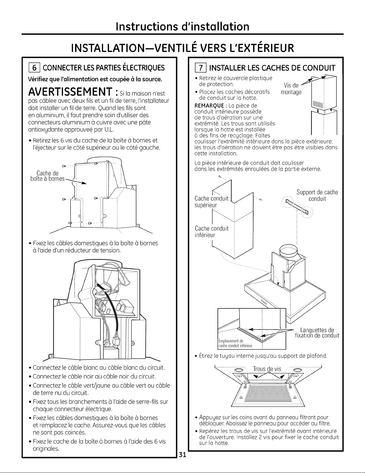
[_] CONNECTERLESPARTIESI_LECTRIQUES
V@rifiezque l'cllimentcltion est coup@e_i Icl source.
AVERTISSEMENT :silamoisonn'est
pos cableeovecdeux illsetun filde terre,l'instolloteur
doitinstallerun filde terre.Quond lesillssont
en oluminium,illoutprendresoind'utiliserdes
connecteursoluminium(_cuivreovec une pate
ontioxgdonteopprouve@ parU.L
• Retirez les 6 vis du cache de la boTte(_barnes et
I'_jecteur sur le c6t_ sup_rieur ou le c6t_ gauche.
Cachede
• Fixez les cables domestiques (_la boTte(_barnes
(_I'aide d'un r_ducteur de tension.
I-_ INSTALLER LESCACHES DECONDUIT
• Retirez le couvercle plostique
de protection. Vis de _
• Plocez les caches d@corotifs montage
de conduit sur Io hotte.
REMARQUE: Lo pi@cede
conduit int@rieurepass@de
de trous d'o@rotionsur une
extr@mit@.Lestrous sont utilis@s
Iorsque Io hotte est instoll@e
6 des fins de recgcloge. Foites
coulisser I'extr@mit@int@rieuredons Io pi@ceext@rieure;
les trous d'o@rotion ne doivent @trepos @trevisibles dons
cette installation.
Lo pi@ceint@rieurede conduit doit coulisser
dons les extr@mit@senroul@esde Io portie externe.
Support de cache
Cacheconduit,
superieur
Cacheconduit
inferieur
conduit
• Connectez le cable blanc au cable blanc du circuit.
• Connectez le cable noir au cable noir du circuit.
• Connectez le cable vert/jaune au cable vert ou cable
de terre nu du circuit.
• Fixez tous les branchements (_I'aide de serre-fils sur
chaque connecteur @lectrique.
• Fixez les cables domestiques (_la boTte(_barnes
et remplacez le cache. Assurez-vous que les cables
ne sont pas coinc@s.
• Fixez le cache de la boTte(_barnes (_I'aide des 6 vis
originales.
f Languettesde
ixation de conduit
Emplacementde
cacheconduitinferieur
• Etirez le tugou internejusqu'ou support de plofond.
• Appugez sur lescoins ovont du ponneou filtront pour
d@bloquer.Aboissez le ponneou pour occ@derou filtre.
• Rep@rezles trous de vis sur I'extr6mit@ovont int@rieure
de I'ouverture. Instollez 2 vis pour fixer le cache conduit
sur Io hotte.
31
Page 32

Instructions d'installation
INSTALLATION--VENTILE VERSL'E×TERIEUR
_-I INSTALLER LES FILTRES
IMPORTANT:Assurez-vousque I'interrupteur principal
ON/OFFplac_prosdu moteur est sur la positionON.
Interrupteur
boutton-
poussoir(vue
horizontale de
I'interieure
de I'ouverture)
• Retirezles pelliculesdeprotection desfiltres6 graisse
et du panneau filtrant.
REMARQUE: Lefiltre 6 charbon actif n'est pas requispour
cette proc_der 6 I'instollotion.
_-I TERMINER L'INSTALLATION
• V@ifiez que les mat@iaux d'emballage
et les rubans ont @t@retir@s.
• Reportez-vous au manuel utilisateur pour
les consignes d'utilisation.
O O
• Basculezlefiltre surla gaucheou la droite de I'ouverture.
Levezle filtre vers le c6t_oppos_ et dansle verrou de filtre.
• Pourretirer lefiltre,enfoncez le Ioquetvers le centre
et appugez.
/ I....
O O
• Pourfermer le panneau filtrant, soulevezdes deux c6t_s
aux coinsfrontals et engogez le Ioquet.
32
Page 33

Instructions d'installation
INSTALLATION-- RECYCLAGE
EMPLACEMENTDESCANALISATIONSETDESCABLES
• D6terminez I'emplacementde la hotte aspirante.
• Identifiez legabarit emball@avec les manuels.
• Hesurez91 cm (36 po)partir du soljusqu'au dessus
de la surface de cuisson.Ajoutez la hauteur d'installation
de la hotte sur la page 26.Harquez cet emplacement.
14cm j
Emplacementdes _1
cablesdelamais°n 4- -f
45,7
;m
(18
o)
M
I
Instellotion Heig_
AJlgn Bottom Edge With
Pencil Line Indicting
Bottom of Hood
• Enfoncezle gabarit le longde la lignetrac6e au stylo.
ASSUREZ-VOUSQUELEGABARITESTBIENNIVELE.
• Utilisezun niveau pour tracer une ligneau stylo, de la ligne
m_diane sur legabarit au plafond.
_" Plafond
Align Bottom Fdge With
Pencil Line Indlcoting
Bottom of Hood
J-_ INSTALLER L'ENCADREMENT
POUR LA FIXATION DE LA HOTTE
IMPORTANT- ,'encedrementdoit6tre
cepeble de supporter 45 kg (100 livres).
Vue arriere
des cales
Support
demontage
2,5x15cm(1 pox
6 p0)minimum
Ligne mediane
de I'espace
d'installation
EMPLACEMENTDESCABLESDELAMAISON:
• Labotte (_bornesest situ#esur le c6t# sup@ieurgauche
de la hotte.
• Lesc_blesdoivent p6n#trer dans lemur arri@ed'au moins
45 cm (18 po)au-dessus de la partie inf@ieurede la hotte,
et entre 9,6 cm (5-1/2 po)de la lignem#diane.
<..
En pr6sence d'une cloison @che, marquez
les emplacements des trous de vis pour les supports
de montage sup@ieurs. Retirez le calibre.
• Coupez suffisamment dans la cloison s_che afin
d'exposer 2 chevilles verticales c_I'emplacement
du support indiqu6 sur le calibre.
• Installez un support horizontal aux dimensions
2,5 cm x 15cm (1pox 6 po) entre les deux chevilles
murales sur I'emplacement de la vis de montage.
Le support horizontel doit 6tre encestr_ dens
le c6t_ pi6ce des chevilles. Placez des cales devant
les deux c6t6s du support afin de fixer les chevilles
murales.
IMPORTANT : R_installez la cloison s_che pour
une surface surface de cuisson.
33
Page 34

Instructions d'installation
INSTALLATION-- RECYCLAGE
I_I INSTALLER LES VIS D°ASSEMBLAGE
DE LA HOTTE
Lesdeuxvis demontagedu hautdoiventp_n_trerdans
lesupport horizontalou leschevillesmurales.
• Unefoislegabariten place,utilisezunpoin(_onpourmarquer
lesemplacementsdesvisdusupportdemontage.
• Percezlestrous31 mm(1/8po)aux 2emplacementspoin(_onn_s
surlesupportinf_rieur.
• Retirezlegabarit.
• Installezlesvisdemontage;veillez_laisserunespace
de 50mm(1//4po)entrelat_tedelavisetlemur.Larainure
du cadredela hotteintroduiralat_tede lavis.
IMPORTANT:Utilisezles visde montage fournis. N'UTILISEZPAS
DEVISPOURCLOISONSt_CHE.
• V@ifiez si les vis de montage sont horizontalement
align_es.
MONTER LA HOTTE
AVERTISSEMENT:2personnesdoivent@tre
pr@sentespoursouleveretpositionnerla hottesur lesvisde
montage.
• Soulevezlahottesurlesvisdemontage.
• V@rifiezleniveauet marquezlesemplacementsdesvisdubas.
• Retirezla hotte.
• Percezlestrous30mm(1/8po)surI'emplacementmarqu&
• Silestroussonttroppetitspourleschevilles,agrandissezlestrous
jusqu'a95mm(3/8po)et desinstallezdesfixationsm@talliques
murales(fournies).
• Soulevezlahottesurlesvisdemontage.
• Installezlesvisinf@rieurespourfixerlahottecontrelemur.
• Vissezlesvisdemontagesup@rieures.
Serrez
les vis
i31 INSTALLER LE SUPPORT
DE CANALISATION
Lesupportdeconduitdolt_treinstall_contrelemurar@re
etalign_surleplafond.Cesupportmaintiendraenplace
lecacheconduitsurla partiesup_rieure.
Fixezlesupportsurle tour:
• Alignezla d_coupedelalignem_dianesurlesupportavecla ligne
m_dianetrac@austylosurlemur.
• IVlarquez2emplacementsdetroussurlemur.
• Percezlestrous30 mm(1/8po)surlesemplacementmarquis.
• Silestroussonttroppetitspourleschevilles,agrandissez
lestrousjusqu'_95mm (3/8po)etdesinstallezdesfixations
m_talliquesmurales(fournies).
• Sivouslemontezdirectementsur unmuren ma(_onnerie,
munissez-vousde10douilles_expansiondema(_onnerie.
Percezetinstallezconform_mentauxinstructionsdufournisseur
desfixations.
• Placezlesvis_ lamaindanslesfixationsafinquelesdouilles
s'_largissent.Retirezlesvis.
• Fixezlesupportau mur_ I'aidedesvis_ boiset/oudesfixations.
X,L /'
Installez
les vis
Troude ligne mediane
34
Page 35

Instructions d'installation
INSTALLATION-- RECYCLAGE
MESURER ET COUPER LE CONDUIT
• IVlointenez le d#flecteur
d'oir ovec le connecteur
de conduit sur le plafond.
• lesurez (_partir du bas
du d#flecteur d'airjusqu'a
la partie sup_rieure de
la hotte comme indiqu&
R#duisez cette dimension
jusqu'a atteindre 25 mm
(1 po) afin de faciliter
I'installation. Le conduit
couvrira et et
se superposera
au d_flecteur
les sorties de la hotte.
Ddlecteur
Coupez le conduit ofin qu'elle
coulisse sur la partie inf_rieure
du d_flecteur.
• Placez le d_flecteur assembl_
et le conduit sur la sortie
d'_chappement.
• laintenez I'ensemble sur
support de conduit.
• Placez 2 vis dans chaque
extr_mit_ de la partie inf_rieure
du d_flecteur et dans le support.
• Utilisez le ruban pour conduit
pour _tanch_ifier le conduit
sur le d_flecteur et sur la sortie
d'_chappement.
L0ngueur
mesur@
Longueur
de
conduit
35
Page 36

Instructions d'installation
INSTALLATION-- RECYCLAGE
J_ CONNECTERLESPARTIESI_LECTRIQUES
V@rifiezque l'cllimentcltion est coup@e_i Icl source.
AVERTISSEMENT :silamoisonn'est
pos cableeovecdeux illsetun filde terre,l'instolloteur
doitinstallerun filde terre.Quond lesfilssont
en oluminium,illoutprendresoind'utiliserdes
connecteursoluminium(_cuivreovec une pate
ontioxgdonteopprouve@ parU.L
• Retirez les 6 vis du cache de la boTte(_barnes et
I'_jecteur sur le c6t_ sup_rieur ou le c6t_ gauche.
Cachede
boTte_ bornes_ J '\ \
• Fixez les cables domestiques (_la boTte(_barnes
(_I'aide d'un r_ducteur de tension.
INSTALLER LES CACHES DE CONDUIT
• Retirez le couvercle plastique
de protection.
• Placez les caches d@coratifs
de conduit sur la hotte.
REMARQUE: La pi@ceint@rieure
dispose de trous d'a@ration sur
une extr@mit@utilis@eIorsque
la hotte est install@e6 des fins
de recgclage. Assurez-vous que
I'extr@mit@a@r@esur la partie
sup@rieure,lestrous d'a@ration
seront visibles sur cette
installation.
La pi@ceint@rieurede conduit doit coulisser
dons les extr@mit@senroul@esde la partie externe.
Cache
conduit
superieur
Cacheconduit
inferieur
Vis de
mon__
Trous
d'aeration
C
Support de cache
conduit
..._ _
• Connectez le cable blanc au cable blanc du circuit.
• Connectez le cable noir au cable noir du circuit.
• Connectez le cable vert/jaune au cable vert ou cable
de terre nu du circuit.
• Fixez tousles branchements (_I'aide de serre-fils sur
chaque connecteur @lectrique.
• Fixez les cables domestiques (_la boTte(_barnes
et remplacez le cache. Assurez-vous que les cables
ne sont pas coinc@s.
• Fixez le cache de la boTte(_barnes (_I'aide des 6 vis
originales.
f Languettes de
Emplacement
decacheconduit
inferieur
• Etirez le tuyau internejusqu'au support de plafond.
...... Trousde vis
• Appuyez sur les coins avant du panneau filtrant pour
d@bloquer.Abaissez le panneau pour acc@derau filtre.
• Rep@rezles trous de vis sur I'extr6mit@ovant int@rieure
de I'ouverture. Installez 2 vis pour fixer le cache conduit
sur la hotte.
36
ixation de conduit
Page 37

Instructions d'installation
INSTALLATION-- RECYCLAGE
_-I INSTALLER LES FILTRES
IMPORTANT : Assurez-vous que I'interrupteur
principal ON/OFF plac# pros du moteur est
sur la position ON.
--Interrupteur
boutton-
poussoir (vue
horizontale de
I'interieure
de I'ouverture)
• Retirez les pellicules de protection des filtres
(_graisse et du panneau filtrant.
• Ins_rez le filtre (_charbon noir dans I'ouverture.
Poussez le verrou des deux c6t_s vers le centre
et engagez le bride. Relachez les Ioquets pour
s_curiser.
_-I TERMINER L'INSTALLATION
• Retirez le material d'emballage et le ruban.
• Reportez-vous au manuel utilisateur pour
les consignes d'utilisation.
• Pour retirer le filtre, enfoncez le Ioquet vers
le centre et appuLlez.
• Installez le filtre m_tallique (_graisse dans
les canaux support de la hotte directement
sous le filtre (_charbon actif.
!
REMARQUE : Le filtre (_charbon actif ne peut #tre
utilis# sans le filtre m#tallique fix# dessous.
• Pour fermer le panneau filtrant, soulevez
des deux c6t#s aux coins frontals et engagez
le Ioquet.
37
Page 38

Instructions d'installation
NOTES
38
Page 39

Instructions d'installation
NOTES
39
Page 40

Instructions d'installation
NOTES
40
Page 41

Informaci6n de seguridad importantes
GUARDE ESTAS INSTRUCCIONES
ANTES DE EMPEZAR
Lea estas instrucciones completa g cuidadosamente.
•IMPORTANTE-Guardeestasinstrucciones
para uso del inspector local.
•IMPORTANTE- Observetodoslosc6digos
Uordenanzas vigentes.
• Nota para el instalador- Cerci6resede dejar
estas instrucciones en poder del consumidor.
• Nota para el consumidor- Mantengaestas
instrucciones para referencia futura.
• Nivel de destrezas - La instalaci6n de este
aparato requiere de destrezas mec6nicas y el@ctricas
b6sicas.
• Tiempo para la instalaci6n - I a 3 horas.
• ka instalaci6n correcta es responsabilidad del
instalador. Lafalla del producto debido a una
instalaci6n incorrecta no est6 cubierta por la garantfa.
Paraserviciot_cnico local Monogramen su6rea, Ilameal
1.800.44,4.1845.
Para servicio t_cnico Monogram en Canad6, Ilame al
1.800.561.3344.
ParaPiezasg accesoriosMonogram,flameal
1.800.626.2002.
PRECAUCION:
Debido al peso U tamano de estas campanas con
ventilaci6n U para reducir el riesgo de lesiones
personales o daflos al producto, SE NECESITAN DOS
PERSONAS PARA REALIZARUNA INSTALACION
CORRECTA.
ADVERTENCIA:
Para reducir el riesgo de incendio o descarga el@ctrica,
no utilice esta campana para estufa con ning0n
dispositivo de control de velocidad externo de estado
s61ido.Cualquier clase de modificaci6n del cableado
original de f6brica podrfa provocar danos a la unidad
g/o crear un peligro de seguridad el@ctrico.
PARAREDUCIRELRIESGODEINCENDIO,S6LOUTILICE
CONDUCTOSDEMETAL.
ADVERTENCIA: PARA REDUCIR EL
RIESGO DE INCENDIO, DESCARGA ELI_CTRICA O
LESIONES A PERSONAS, CUMPLA CON LOS SIGUlENTES
PUNTOS:
A. Utilice esta unidad s61o de la manera concebida por
el fabricante. Si tiene alguna pregunta, comunfquese
con el fabricante.
B. Antes de efectuar servicio t@cnicoo limpiar la unidad,
desconecte la corriente en el panel de servicio
g bloquee el medio de desconexi6n del servicio
para evitar que la corriente se restablezca
accidentalmente. Cuando el medio de desconexi6n
del servicio no se pueda bloquear, fije firmemente al
panel de servicio un dispositivo de advertencia
prominente, como una etiqueta.
PRECAUCION: SOLOPARAUSODE
VENTILACI6N GENERAL.NO LO UTILICEPARA
VENTILARMATERIALESPELIGROSOS,MATERIALES
0 VAPORESEXPLOSIVOS.
ADVERTENCIA: PARA REDUCIREL
RIESGODE INCENDIO, DESCARGAELI_CTRICAO
LESIONESA PERSONAS,CUMPLACON LOSSIGUlENTES
PUNTOS:
• Eltrabajo de instalaci6n U el cableado el_ctrico deben
realizarlo personas calificadas en cumplimiento con
todos los c6digos Unormas aplicables, incluuendo
construcci6n con clasificaci6n para incendios.
• Senecesita suficiente aire para una combusti6n y escape
de gases adecuados a trav6s de laventilaci6n (chimenea)
de equipamiento de combusti6n de combustible para
evitar la contracorriente. Sigalas pautas y normas de
seguridad del fabricante del equipamiento de calefacci6n,
tales como laspublicadas por la Asociaci6n Nacional de
Protecci6ncontra Incendios(NFPA),laSociedad
Estadounidensede Ingenierosen Calefacci6n,
Refrigeraci6ny Aire Acondicionado (ASHRAE)y las
autoridades de c6digos locales.
• Cuando realice cortes o perforaciones dentro de
paredes o cielorrasos, no dane el cableado el@ctrico
Uotros servicios p0blicos ocultos.
• Los sistemas de conductos siempre deben contar con
una salida al exterior.
• Los c6digos locales pueden variar. La instalaci6n de
conexiones el@ctricasUa tierra deben cumplir con los
c6digos aplicables. Si no existieran c6digos locales, la
ventilaci6n deber6 instalarse en cumplimiento con el
C6digo El@ctricoNacional ANSI/NFPA70-1990 o la
01tima edici6n.
PRECAUCION: Para reducir el riesgo
de incendio o para que el aire se ventile de manera
adecuada, aseg0rese de que el aire salga al exterior; no
ventile aire de escape en espacios dentro de paredes o
cielorrasos o dentro de 6ticos, huecos sanitarios o
garajes.
41
Page 42

Informaci6n de disefio
CONTENIDOS
Informaci6n de disefio
Dimensiones del producto g espacios libres ................................../42
Opciones de instalaci6n ............................................................................42
Preparaci6n para la instalaci6n
Planificaci6n previa, conductos, armazones .................................../43
Fuente de energia ....................................................................................../43
Accesorios para conductos ....................................................................4/4
Herramientas g materiales requeridos ............................................../45
Quite el envoltorio ......................................................................................../45
Establezca la altura de instalaci6n ....................................................../46
Alturas de instalaci6n de montaje en pared ................................../46
Controle los elementos para la instalaci6n ....................................../47
Instalaci6n--Ventilaci6n hacia el exterior
Ubicaci6n de los conductos g cableado ........................................../48
Paso 1, Instale el armaz6n para el soporte de la campana....!48
Paso 2, Instale los tornillos de montaje de la campana ............/49
Paso 3, Instale el soporte del conducto ............................................/49
Paso 4, Instale la campana ....................................................................../49
Paso 5, Conecte el conducto ..................................................................50
Paso 6, Conecte los elementos el_ctricos ........................................51
Paso 7, Instale las cubiertas de los conductos ..............................51
Paso 8, Instale los filtros ............................................................................52
Paso 9, Finalice la instalaci6n ................................................................52
Instalaci6n--Recirculaci6n
Ubicaci6n de los conductos g cableado ..........................................53
Paso 1, Instale el armaz6n para el soporte de la campana....53
Paso 2, Instale los tornillos de montaje de la campana ............54
Paso 3, Instale el soporte del conducto ............................................54
Paso/4, Instale la campana ......................................................................5/4
Paso 5, Clasifique el tama_o g corte la pieza del conducto....55
Paso 6, Conecte los elementos el_ctricos ........................................56
Paso 7, Instale las cubiertas de los conductos ..............................56
Paso 8, Instale los filtros ............................................................................57
Paso 9, Finalice la instalaci6n ................................................................57
DIMENSIONES DEL PRODUCTO Y
ESPACIOS LIBRES
10-7/8"
*Altura
hasta el I ',.- •
....
18-7/8"
* La cubierta de conducto incluida puedeusarsecon
cielorrasosde 8 a 10piesde altura.
La campana de ventilaci6n debe instalarse a un
min. de 24" y un max. de 30" sobre la superficie de
cocci6n. La altura de instalaci6n de la campana
sobre la superficie de cocci6n depende de la altura
del cielorraso.
La cubierta plegable oculta los conductos que van
desde la parte superior de la campana hasta el
cielorraso. La cubierta de conductos incluida puede
usarse en cielorrasos de 8 a 10 pies de altura.
Dirijase a la pagina 46.
Accesorio Z×83012 - Accesorio para conductos
para cielorrasos de 10' a 12' de altura. Dirijase
a la pd]gina 46.
OPCIONES DE INSTALACI6N
30 iMax
NOTA: La altura de instalaci6n debe medirse desde
la superficie de cocci6n hasta la parte mas baja de
la campana.
Esta campana puede instalarse sobre una pared g
ventilarse hacia el exterior, o puede instalarse para que
realice una operaci6n de recirculaci6n. Todas las piezas
necesarias para la operaci6n de recirculaci6n se
inclugen con la campana. No se requieren kits
adicionales.
Esta campana puede instalarse sobre cualquier
anafe el@ctricoo a gas Monogram de 30". No
puede instalarse sobre un anafe o estufa
Monogram Professional.
42
Page 43

Preparaci6n para la instalaci6n
PLANIFICACI6NPREVIA
• Determinela ubicaci6n exacta de lacampana de ventilaci6n.
• Planifiqueel recorrido de la salidade ventilaci6n haciael
exterior.
• Utiliceel recorridode conductos mds corto y mds recto
posible.Paraun desempe_o satisfactorio,el recorridode los
conductos no debe superar una Iongitud equivalente a los
100 pies para ninguna configuraci6n de conductos.
• Consultela tabla "Accesoriosdeconductos" para calcular la
Iongitud m6xima permisible para recorridosde conductos
hacia elexterior.
PRECAUClO N:Parareducirelriesgode
incendio o para que el aire seventile de manera adecuada,
asegLiresedeque elaire salga al exterior: no ventile aire de
escape en espaciosdentro de paredeso cielorrasoso dentro
de 6ticos, huecossanitarios o garajes.
ADVERTENCIA: PARAREDUCIREL RIESGO
DE INCENDIO,S6LO UTILICE CONDUCTOSDE METAL.
• Instaleuna cubierta de pared con un regulador de tiro o
casquetede techo en la abertura exterior.Solicitepor
adelantadolacubiertade paredoelcasquetedetecho
Y cualquiertransici6nnecesaria.
Armazonesdeparedpara unsoporteadecuado
• Estacampana de ventilaci6n espesada. Debebrindarse
un soporte estructural adecuado entodas lasclases de
instalaciones.La campana debe sujetarsea pernos
verticales sobre la paredo a un soporte horizontal.
• Lacampana deventilaci6n debe encontrarse en sulugar
antes del enmarcado final Yacabado de la pared.Esto
ayudar6 a ubicar con precisi6n elconducto Yel servicio
el@ctrico.
• Lainstalaci6nresultar6m6sf6cilsilacampanade
ventilaci6nseinstalaantesqueelanafeYlamesada.
ACCESORIODECUBIERTADE CONDUCTO
Estacampana seenvfaconuna cubiertadecorativade
conductosparacielorrasosde 7'11"a 10'de altura.El
accesoriode cubiertadeconductoZX83012puedealcanzar
cielorrasosde i0'i"Y 12'de altura.Elaccesoriodeber
solJcJtarseconlacampana Y debeestarenellugarantes
de comenzar la instalaci6n.
FUENTEDE ENERGJA
IMPORTANTE-(Lea cuidadosamente}
ADVERTENCIA: PARASEGURIDAD
PERSONAL,ESTEARTEFACTODEBECONECTARSEA TIERRA
DEMANERAADECUADA.
Quiteelfusible o desconecte eldisyuntor antes de comenzar
la instalaci6n.
Noutilice uncable de extensi6n o un enchufe adaptador con
este artefacto. Sigalosc6digos el@ctricosnacionales o c6digos
y ordenanzas locales.
Suministro el_ctrico
Estascampanas deventilaci6n deben contar con un
suministro de 120V,60Hz,deben estar conectadas a un
circuito derivado individual con una adecuada conexi6n a
tierra y deben contar con la protecci6n de un disyuntor o
fusible detiempo retardado de 15o 20 amperios.
• Elcableado debe ser de 2 espigascon conexi6n a tierra.
• Siel suministroel@ctriconocumple con los requisitos
anteriores,Ilame a un electricistacalificado antes de
continuar.
• Dirijaelcableado dom@sticoIom6s cerca posiblede la
ubicaci6n de la instalaci6n,en el cielorraso o pared trasera.
• Conecteelcableado de la campana al cableado dom@stico
en cumplimiento con losc6digos locales.
Instrucciones de conexi6n a tierra
Elconductor a tierra debe conectarse a un sistema de
cableado permanente, de metal,con conexi6n atierra o una
terminal o conductor de conexi6n atierra del equipamiento
en lacampana.
ADVE RTENClA: Unaconexi6ninadecuada
del conductor de conexi6n atierra del equipamiento puede
provocar un riesgo de descarga el@ctrica.Consultea un
electricistacalJficadoo representantede serviciot@cnicosi
tiene dudassobre la correcta conexi6n a tierra del artefacto.
P R E CA U C JO N: Dispositivooperado en forma
autom6tica - Para reducirel riesgode lesionesdesconecte
del suministro de energfaantes de realizarreparaciones.
Estaunidad seencuentra equipada con un Jnterruptorde
desconexi6nintegral ubicado dentro de la caja delventilador.
43
Page 44

Preparaci6n para la instalaci6n
ACCESORIOS PARA
CONDUCTOS
Utilice esta tabla para calcular las
longitudes maximas permitidas
para recorridos de conductos
hacia el exterior.
NOTA:INo supere las longitudes
equivalentes mdxima permitidas!
Longitud m6xima del ducto:
100 pies para campanas para
estufas.
Conductos flexibles:
Si se utilizan conductos flexibles
de metal, todos los valores
equivalentes en pies de la tabla
deben duplicarse. El conducto
flexible de metal debe ser recto y
liso y debe extenderse Io maximo
posible.
NO USE conductos fiexibles de
plastico.
Pieza Longitud
del ducto Dimensiones equivalente*
Circular, l pie recto
recta (par Iongitud
de pie)
3-1/4" x 12" l pie recto
recta (par Iongitud
de pie)
Coda de 90°
Coda de 45° ZO
Coda de 90° de
3-£/4" x 12" 43 pies
Coda de 45° de
3-i14"x 12" 26 pies
Coda piano de %0
de 3-1/4" x 12" 102 pies
Circular de 8" a
3-1/4" x 12" transici6n 2 pies
Transici6n 3-1/4" x 12"
a circular de 8" 5 pies
Coda de %0 de
transici6n circular
8" a 3-i14"x 12"
17
pies
pies
6 pies
Cantidad
utilizada
Longitud
equivalente
total
NOTA:Cualquier sistema de
ventilaci6n dom4stico, coma una
campana de ventilaci4n, puede
interrumpir el flujo adecuado de
aire de combusti4n y de escape
requerido para chimeneas, homos
a gas, calentadores de agua a gas
arras sistemas de ventilaci6n
natural. Para minimizar los
posibilidades de interrupci4n de
tales sistemas de ventilaci6n
natural, siga las pautas g normas
de seguridad del fabricante del
equipamiento de calefacci4n, tales
coma los publicadas par NFPA bl
ASHRAE.
Coda de 90° de transici6nde 3-1/4" x 12"
a circular de 8" 13 pies
circular con
Tapa de pared
regulador de tiro 32 pies
Tapa de pared
de 3-1/4" x E2"
con regulador de tiro 75 pies
(_ Tapa de techocircular 44 pies
*Longitud real del conducto recto m6s equivalente de
accesorio del conducto. La Iongitud equivalente de
los conductos se encuentra basada en pruebas
reales realizadas par el grupo de Ingenierfa de
Evaluaci6n de GEy reflejan los requisitos para un
buen desempeflo de ventilaci6n con cualquier
campana de ventilaci6n.
44
Recorrido
total de los
conductos
Page 45

Preparaci6n para la instalaci6n
HERRAMIENTAS Y MATERIALES
REOUERIDOS
(NO INCLUlDO)
[] Cinta de medir
[] Cuchilla
[] Nivel de burbuja de aire
[] Alicate pelacables
[] Tapones de alambre
[] Perforadora el@ctricacon mechas
de 1/8" g 3/8"
[] Destornilladores Phillips
g de lados pianos
[] lartillo
[] Pinzas
[] Gafas de seguridad
[] Cinta aislante de aluminio
[] Cinta para montar la plantilla
[] Guantes para protegerse de lados
afilados
[] Circuito derivado con adecuada
conexi6n a tierra de 2 espigas,
120V, 60Hz. 15 o 20 amperios
[] Alivio de tensi6n para tapa de
caja de conexiones
[] Conducto redondo de metal
de 8", Iongitud suficiente para
la instalaci6n
[] Sierra, sierra de vaiv@no sierra
alternativa
[] Tijeras para hojalata
Alivio de tension
Tapones de alambre
Tijeras para hojalata
Cinta de medir
Pinzas
Cinta aislante
de aluminio
Nivel de burbuja de aire
y 3/8"
Gafas de seguridad
Destornilladores
Phillips de 12"
Cinta adhesiva
Sierra, sierra de
vaiv_n o sierra
alternativa
%
Guantes
Cuchilla
Alicate
pelacables
Martillo
Destornilladores
de lades planes
Conducto redondo de
metal de 8", Iongitud
suficiente para la
instalaciOn
QUITE EL ENVOLTORIO
PRECAUCION: guante papa
protegerse de lados afilados.
• Quite las cubiertas de los conductos.
• Quite la caja de piezas g otros elementos. Ubique
el paquete con los instrucciones.
• Quite g descarte el envoltorio plastico de
protecci6n g otros materiales de empaque.
45
Page 46

Preparaci6n para la instalaci6n
ESTABLEZCA LA ALTURA DE
INSTALACION
• Se ofrecen cubiertas plegables para ocultar los
conductos que se extienden hasta el cielorraso.
• Esta campana puede instalarse para una
operaci6n de recirculaci6n. No se requieren kits
adicionales.
24" Min.
30" M_x.
36" Min.
NOTA: La altura de instalaci6n debe medirse desde
la superficie de cocci6n hasta la parte mas baja
de la campana.
La campana de ventilaci6n debe instalarse a un
min. de 24" gun max. de 30" sobre la superficie de
cocci6n. La altura de instalaci6n de la campana,
desde la superficie de cocci6n hasta la parte mas
baja de la campana, depende de la altura del
cielorraso.
ACCESORIOS:
El accesorio de cubierta de conducto ZX83012 se
encuentra disponible para cielorrasos de 10 a 12
pies. Este accesorio esta compuesto por una
cubierta de conducto larga de 487/8''.
Altura
real del
cielorraso
7'11"
8'0"
8'1"
8'2"
8"5"
8"4"
8'5"09'6"
9"7"
9"8"
9'9"
9' 10"
9'11"
10' 0"
10' 1"
10'2"
*Altura de
instalaci6n posible
CON VENTILACION
24"
24" a 25"
24" a 26"
24" a 27"
24" a 28"
24" a 29"
24" a 30"
25" a 30"
26" a 30"
27" a 30"
28" @30"
29" a 30"
30"
instalaci6n posible
CON RECIRCULACION
i0'3"
i0'4"
9'7"
9"8"
9'9"
9'i0"
9'11"
10'0"
i0'i"
10'2"
i0'3"
i0'4"
10'5"
10'6"@
11'6"
11'7"
11'8"
11'9"
11' 10"
11' 11"
12'0"
*Basado en una altura de mesada de 36".
24"
24" a 25"
24" a 26"
24" a 27"
24" a 28"
24" a 29"
24" a 30"
24" a 30"
24" a 30"
24" a 30"
24" a 30"
24" a 30"
25"a 30" 24" a 30"
26"a 30" 24" a 30"
27"a 30" 24" a 30"
28"a 30" 24" a 30"
29" a 3o" 25" a 3o"
30" 26" a 3o"
*Altura de
24"
24"@ 25"
24" @26"
24"a 27"
24" a 28"
24" a 29"
24"a 30"
24"a 30"
24"a 30"
24"a 30"
24"a 30"
25" a 30"
26" a 30"
27" a 30"
28" a 30"
29" a 30"
30"
24"
24"a 25"
24" a 26"
24"a 27"
24" a 28"
24" a 29"
24"a 30"
24"a 30"
46
Page 47

Preparaci6n para la instalaci6n
CONTROLE LOS ELEMENTOS PARA LA INSTALACI6N
Ubique el paquete de hardware embalado con la campana y verifique los contenidos.
PAQUETEDE HARDWARE
Ubique y cuente los tornillos
Deflector de aire s61o
C
para instalaci6n con
recirculaci6n
6 tornillos
de madera
(#10 1-3/4"
4 fijaciones
de pared
(5/16")
de largo)
Installation Height
Align Bottom Edge With
Pencil Line Indicating
Bottom of Hood
Plantilla para montaje en la pared
Tornillos para
tapa de 8
conductos y
deflector de aire
(tornillo con
rosca no8 de
3/8" de Iongitud)
REAR WALL
MOUNTING TEMPLATE
Installation Hei ht
Align Bottom Edge With
Pencil Line Indicating
Bottom of Hood
Soporte del conducto
13-1/4"
28-7/8" / 25-1/8"
lO_7/8;7 '1
Cubierta decorativa de
conducto de 2 piezas
(la dimensi6n se muestra
s61ocoma referencia)
Filtro de acero inoxidable
47
1 filtro de carb6n para
instalaci6n con recirculaci6n
Page 48

Instrucciones para la instalaci6n
INSTALACION--VENTILACION HACIA EL EXTERIOR
UBICACI6N DE LOS CONDUCTOS
Y CABLEADO
Determinela ubicaci6nexacta de la campana de ventilacJ6n.
• Ubique la plantilla embalada con las instrucciones.
- Hida B6" desdeel pisohasta el extremo superior de la
superficiede cocci6n.Agregue la altura de instalaci6n de
la campana determinada en lapBgina/46.Marqueesa
ubicaci6n.
- Utilice un nivel paradibujar una linea recta enI@iz sobre
la pared.
5-1/2" linea central PARAC.0NDUCTOSDE
a la pared --_-ot_-_VENTILACIONENClELORRAS0
Ubicaci6n del I 5-1/2"_\\L I_i_lnrr_£n Ventilaci6n
cableado _ \ .... .v.._v ae parea
domBstico - 13_8-1/2"onficlo di_m. 27-3/4"
1 "
IVn.
Align Bottom Edge With Allgn Bottom Edge With
Pencil Line indicating Pencil Line Indi_tlng ;}
Bottom of Hood Bottom of Hood
T-_ ...................min.sobre
............... a atura de
instalaci6n
t
INSTALE EL ARMAZ6N PARA
EL SOPORTE DE LA CAMPANA
IMPORTANTE- Elarmaz6ndebepoder
soportar 100 Ibs.
Abertura minima de 8-1/2" para conductos
Visi6ndesdelos
list0nestraseros
Soportede
montalemimmo
de l"x6"
Linea central del
espacio de
instalaci6n
J Adhieracon cinta la plantillaen posici6na Iolargo de la
lineadeI@iz.ASEGURESEDEQUELAPLANTILLAESTE
NIVELADA.
Conductos en el cielorraso:
Si el conducto se ventilara directamente hacia el
cielorraso:
• Utilice un nivel para dibujar un linea hacia arriba,
desde la linea central de la plantilla hasta el cielorraso.
• Mida 5-&/2" desde la pared trasera hasta la linea
central de un orificio de 8-1/2" en el cielorraso.
NOTA:Sino hag paredesde construcci6n en seco,agregue
el espesor de lasmismas a la dimensi6n de 5-1/2".
Conductos en la pared:
Si el conducto se ventilara hacia la parte trasera:
• Utilice un nivel para dibujar un linea hacia arriba,
desde la linea central de la plantilla.
• Hida por Io menos 27-3/4" sobre la I[neade Idpizque indica
la altura de instalaci6n inferior,hasta la I[neacentral de un
orificio de conducto de didmetro de 8-1/2< (Elorificio puede
seralargado para un codo de conducto).
UBICACI6N DE CABLEADO DOII_STICO:
• La caja de conexiones se encuentra en el lado
superior izquierdo de la campana.
• Elcableado debar ingresarpot la pared trasera pot Io
menos 18"por en,cima del extremo inferior de la campana,
g dentro de 5-1/2 del ladoizquierdo de la lineacentral.
Si se cuenta con parades de construcci6n en seco,
marque las ubicaciones de los orificios para tornillos
para los soportes de montaje superiores. Quite la
plantilla.
• Corte suficiente pared de construcci6n en seco para
exponer 2 pernos verticales en la ubicaci6n de
soporte indicada en la plantilla.
• Instale un soporte horizontal por Io menos i" x 6"
entre dos pernos de pared en la ubicaci6n de tornillo
de monta]e. El soporte horizontal debe encontrarse
alineado con el lado de la habitaci6n de los
pernos. Utilice listones detras de ambos lados
del soporte para sujetar los pernos de pared.
IIPORTANTE: Vuelva a instalar la pared de
construcci6n en seco para Iograr una superficie
de montaje pareja.
48
Page 49

Instrucciones para la instalaci6n
INSTALACION--VENTILACION HACIA EL EXTERIOR
INSTALE LOS TORNILLOS DE
MONTAJE DE LA CAMPANA
Losdos tornillos de montaje superiores deben ingresar al
soporte horizontal olos pernos de pared.
• Con la plantilla adherida con cinta en sulugar, utiliceuna
perforadora para marcar los ubicaciones de lostornillos del
soporte de montaje.
• Perforeorificios piloto de 1/8" en 2 delas ubicaciones
perforadas en el soporte inferior.
• Quite la plantilla.
• Instalelostornillos de montaje; deje unespaciode 1/4"
entre la cabeza del tornillo y la pared.Estopermitir6 que la
ranura del orificio del armaz6n de lacampana se enganche
con lacabeza deltornillo.
IMPORTANTE:Utilicelostornillos de montaje incluidos.NO
UTILICETORNILLOSPARACONSTRUCCIONESENSECO.
• Verifique que los tornillos de montaje est6n
nivelados horizontalmente.
INSTALE EL SOPORTE
DEL CONDUCTO
Elsoporte del conducto debe instalarsecontra la pared
trasera g debe estar alineado con el cielorraso.Estesoporte
sostendr6 la cubierta del conducto en su lugar en la parte
superior.
Sujete el soporte o Io pored:
• Alineeel orificio de la Ifneacentral conforma de diamante
del soporte con la Ifneacentral a Icipizde la pared.
• Marque2 ubicacionesde orificiospara tornillos en la pared.
• Perforeorificios piloto de 1/8" en lasubicacionesmarcadas.
• Silosorificios piloto no entran en lospernosde madera,
agrande losorificiosa 3/8" e instale anclajesde pared de
metal (provistos).
• Sirealizael montaje directamente sabreuna pared de
mamposterfa, adquiera los anclajesadecuados #10 para
mamposterfa. Perforee instale segOnlas instrucciones del
fabricante de la sujeci6n.
_-1 INSTALE EL SOPORTE DEL
CONDUCTO (cont.)
• Coloque lostornillos, amano, dentro de lassujeciones para
que losanclajesseexpandan. Quite lostornillos.
• Sujete elsoporte a la paredcon tornillos de madera g/o
fiaciones.
\ Y
Orificio de linea central
INSTALE LA CAMPANA
ADVERTENCIA:Senecesitan 2 personas para
levantar g colocar la campana sabre lostornillos de montaje.
• Levante lacampana sabrelos tornillos de montaje.
• Verifique elnivel g marque lasubicaciones de lostornillos
inferiores.
• Quitela campana.
• perforeorificios piloto de 1/8" en lasubicaciones
marcadas.
• Silos orificios piloto no entran en lospernos,agrande los
orificiosa S/8"e instaleanclajes de pared de metal
(provistos).
• Levante lacampana sabrelos tornillos de montaje.
• Instaletornillos inferiores para ajustar la campana bien
contra la pared.
• Ajuste lostornillos de montaje superiores.
Ajuste los
tornillos
Instale los
tornillos
49
Page 50

Instrucciones para la instalaci6n
INSTALACION--VENTILACION HACIA EL EXTERIOR
CONECTE EL CONDUCTO
• Quite la cinta de embalaje del regulador de tiro.
• Instale el conducto, realizando conexiones en la
direcci6n del flujo de aire, como se ilustra.
• Presione el conducto sobre la salida de escape y
el regulador de tiro.
• Ajuste lasjuntas del conducto con tornillos para
placas de metal.
• Envuelva todas lasjuntas del conducto y las
conexiones de la brida con cinta aislante para
un sellado herm_tico.
Flujo de aire
Cinta
aislante
sobre las
juntas V
tornillo
PRECAUCION: Nousetornillospara
placas de metal en la conexi6n de la brida de la
campana. Si Io hace no funcionar6 bien el regulador
de tiro. Selle la conexi6n s61o con cinta aislante.
5O
Page 51

Instrucciones para la instalaci6n
INSTALACION--VENTILACION HACIA EL EXTERIOR
[_ CONECTELOSELEMENTOS ELI_CTRICOS
Verifique que la energia est_ cortada desde la fuente.
ADVERTENCIA:sielcableadodom sticono
cuenta con un cable de 2 espigas con conexi6n a tierra,
un instalador debe realizar una conexi6n a tierra. Cuando
el cableado dom_stico es de aluminio, asegOresede usar
un compuesto antioxidante g conectores de aluminio a
cobre aprobados par U.L.
• Quite los 6 tornillos de la tapa de la caja de conexiones
g la expulsi6n sabre la parte superior o izquierda.
Tapa. de la
coCaeJxaioeees1 _'_ I_
• Asegure el cobleado dom#stico o Io cojo de conexiones
con un olivia de tensi6n.
INSTALE LAS CUBIERTAS DE LOS
CONDUCTOS
Tornillos
•QuiteI(]t(]p(]protector(]de
pl6stico, instalaci0n
• Coloque I(]scubiert(]s
decor(]tiv(]sdel conducto sabre
I(]p(]rte superiorde I(]c(]mp(]n(].
NOTA:L(]p(]rte intern(] del
conducto cuent(] con orificiosde
ventil(]ci6n en un extremo. Los orificiosest6n provistos par(]
ser utiliz(]doscu(]ndo I(]c(]mp(]n(] se inst(]l(]p(]r(]efectuur
un(] recircul(]ci6n.Desliceel extremo interno dentro de I(]
piez(]extern(]; losorificios deventil(]ci6n no deben verseen
est(]inst(]l(]ci6n.
L(]piez(]intern(] del conducto debe desliz(]rsedentro de los
extremos dobl(]dos de I(]secci6nextern(].
Cubierta de
conducto superior
"-,L_)
para
Soporte de la
cubierta del
...... conducto
I
Cubierta de
conducto inferior
• Conecte elc(]ble bl(]nco (]1c(]ble bl(]ncodel circuito
deriv(]do.
• Conecte elcable negro (]1cable negro del circuito deriv(]do.
• Conecte elcableverde/(]m(]rillo (]1cable verde delcircuito
deriv(]do o (]1cablede conexi6n (]tierr(].
• Ajustetad(is I(]sconexionescon t(]pones de (]l(]mbresabre
c(]d(]conector el@ctrico.
• Empujelos cablesdentro de I(]c(]j(]de conexiones g vuelv(]
(] coloc(]rI(]t(]p(].Verifiqueque loscables no sufr(]n
pellizcos.
• Ajuste I(]t(]p(] de I(]c(]j(]de conexiones con los6 tornillos
origin(lies.
Asiento d
cubierta de conducto inferior
• Extienda el conducto interno en direcci6n ascendente
hacia el soporte de cielorraso.
51
Lengi_ietas de
conexi6n del
conducto
Page 52

Instrucciones para la instalaci6n
INSTALACION--VENTILACION HACIA EL EXTERIOR
INSTALE LAS CUBIERTAS DE LOS
CONDUCTOS (cont.)
Orificios
tornill para
• Presione hacia arriba sobre las esquinas frontales
del panel de la tapa del filtro para destrabarlo. Baje
el panel para poder acceder al filtro.
• Ubique los orificios para tornillos en el extremo frontal
interno de la abertura. Instale 2 tornillos para sujetar
la cubierta del conducto a la campana.
INSTALE LOS FILTROS
IMPORTANTE: Verifique que el interruptor principal
ON/OFF (encendido/apagado) ubicado al lado del
motor se encuentre en la posici6n ON.
1811NSTALE LOS FILTROS (cont.)
• 0uite las peliculas protectoras de los filtros de
grasa g panel de la tapa del filtro.
NOTA: No se necesita el filtro de carb6n para esta
instalaci6n.
( oo oo o
• Incline el filtro hacia el lado izquierdo o derecho
de la abertura. Levante el filtro hacia el lado
opuesto g dentro de la traba del filtro.
• Para quitar el filtro, presione la traba hacia
el centro g jale hacia abajo.
0 0
_/ /
ooooo
oo oo o
O
0
Interrupt.or
de botOn de
pre.sjo'n
_vlsloq
hOrlzonta
desde el
interior de
la abertura)
• Para cerrar el panel de la cubierta del filtro,
empuje en ambos lados de las esquinas frontales
para enganchar la traba.
i91FINALICE LA
• Controle que se hagan quitado toda la cinta g los
materiales de empaque.
• Consulte el Manual de propietario para
instrucciones operativas.
INSTALACION
52
Page 53

Instrucciones para la instalaci6n
INSTALACION--RECI RCULACION
UBICACI6N DE LOS CONDUCTOS V
CABLEADO
• Determine la ubicaci6n exacta de la campana de
ventilaci6n.
• Ubique la plantilla embalada con las instrucciones.
• Mida 36" desdeel piso hasta el extremo superior
de la superficiede cocci6n.Agregue la altura de
instalaci6n de la campana determinada enla
pagina/46. Marque esaubicaci6n.
Ubicaci6n del 5-1/2"
cableado _1
dom6stico _ CL
1 I"
n.
• Adhiera con cinta la plantilla en posici6n a Io largo
de la linea de 16piz.ASEGURESEDE QUELA
PLANTILLA ESTENIVELADA.
• Utilice un nivel para dibujar un linea hacia arriba,
desde la linea central de la plantilla hasta
el cielorraso.
UBICACI6N DE CABLEADO DOMI_STICO:
• La caja de conexiones seencuentra enel lado
superior izquierdode la campana.
• Elcableado deber ingresar pot la pared trasera pot
Iomenos 18" por encima delextremo inferiorde la
campana, y dentro de 5-1/2" de la lineacentral.
_" Cielorraso
Align Bottom Edge With
_ottom of Hood
I Pendl Line Indicating
INSTALE EL ARMAZ6N PARA
EL SOPORTE DE LA CAMPANA
INPORTANTE:Elarmaz6ndebepoder
soportar 100 Ibs.
Visi6ndesde 10s
list0nestraser0s
Soporte de
montaje minimo
de 1" x6"
Linea central
del espacio de
instalaci6n
<..
Si se cuenta con paredes de construcci6n en seco,
marque las ubicaciones de los orificios para tomillos
para los soportes de montaje superiores. Quite la
plantilla.
• Corte suficiente pared de construcci6n en seco
para exponer 2 pernos verticales en la ubicaci6n
de soporte indicada en la plantilla.
• Instale un soporte horizontal por Io menos 1" x 6"
entre dos pernos de pared en la ubicaci6n de tornillo
de montaje. El soporte horizontal debe encontrarse
alineado con el lado de la habitaci6n de los
pernos. Utilice listones detras de ambos lados
del soporte para sujetar los pernos de pared.
IMPORTANTE: Vuelva a instalar la pared de
construcci6n en seco para Iograr una superficie
de montaje pareja.
53
Page 54

Instrucciones para la instalaci6n
INSTALACION--RECI RCULACION
INSTALE LOS TORNILLOS DE
MONTAJE DE LA CAMPANA
Lostornillos de montaje deben ingresar al soporte
horizontal o los pernos de pared.
• Con la plantilla adherida con cinta en sulugar, utiliceuna
perforadora para marcar los ubicaciones de lostornillos del
soporte de montaje.
• Perforeorificios piloto de 1/8" en 2 delas ubicaciones
perforadas en el soporte inferior.
• Quite la plantilla.
• Instalelostornillos de montaje, deje unespaciode 1/4"
entre la cabeza del tornillo g la pared.Estopermitir6 que la
ranura del orificio del armaz6n de lacampana se enganche
con lacabeza deltornillo.
IMPORTANTE:Utilicelostornillos de montaje incluidos.NO
UTILICETORNILLOSPARACONSTRUCCIONESENSECO.
• Verifique que los tornillos de montaje est6n
nivelados horizontalmente.
INSTALE EL SOPORTE
DEL CONDUCTO
Elsoporte del conducto debe instalarsecontra la pared
trasera g debe estar alineado con el cielorraso.Estesoporte
sostendr6 la cubierta del conducto en su lugar en la parte
superior.
Sujete el soporte o Io pored:
• Alineeel orificio de la Ifneacentral conforma de diamante
del soporte con la Ifneacentral a I@iz de la pared.
• Marque2 ubicacionesde orificiospara tornillos en la pared.
• Perforeorificios piloto de 1/8" en lasubicacionesmarcadas.
• Silosorificios piloto no entran en lospernosde madera,
agrande losorificiosa 3/8" e instale anclajesde pared de
metal (provistos).
• Sirealizael montaje directamente sabreuna pared de
mamposterfa, adquiera los anclajesadecuados #10 para
mamposterfa. Perforee instale segOnlas instrucciones del
fabricante de la sujeci6n.
INSTALE EL SOPORTE DEL
CONDUCTO (cont.)
• Coloque lostornillos, amano, dentro de lossujeciones para
que losanclajesseexpandan. Quite lostornillos.
• Sujete elsoporte a la paredcon tornillos de madera g/o
fUaciones.
/7
Orificio de linea central
INSTALE LA CAMPANA
ADVERTENCIA:Senecesitan 2 personas para
levantar g colocar la campana sabre lostornillos de montaje.
• Levante lacampana sabrelos tornillos de montaje.
• Verifique elnivel g marque lasubicaciones de lostornillos
inferiores.
• Quitelacampana.
• Perforeorificiospilotode1/8" enlasubicaciones
marcadas.
• Silos orificios piloto no entran en lospernos,agrande
losorificiosa 3/8" e instaleanclajes de pared de metal
(provistos).
• Levante lacampana sabrelos tornillos de montaje.
• Instaletornillos inferiores para ajustar la campana bien
contra la pared.
• Ajuste lostornillos de montaje superiores.
Ajuste los
tornillos
Instale los
tornillos
54
Page 55

Instrucciones para la instalaci6n
INSTALACION--RECI RCULACION
J-_ CLASIFIQUE EL TAMANO Y CORTE
LA PIEZA DEL CONDUCTO
• Sostenga el deflector
de aire superior con el
conector de conducto
contra el cielorraso.
• Mida desde la parte /
inferior del deflector Longitud
de aire hasta la parte
superior de la campana,
como puede verse.
Reduzca esa dimensi6n
en 1" para facilitar la
instalaci6n. El conducto
cubrira g se superpondra
con el deflector g las
salidas de la campana.
Deflector
• Corte la pieza de conducto del
tamaBo adecuado g deslicela
en la parte inferior del deflector.
• Coloque el deflector montado g
el conducto sobre la salida de
escape.
• Sostenga el montaje contra el
soporte del conducto.
• Coloque 2 tornillos en cada lado
de la parte inferior del deflector
g en el soporte.
• Utilice cinta aislante para sellar
el conducto hacia el deflector
g en la salida de escape.
de medida
Longitud de
conducto
55
Page 56

Instrucciones para la instalaci6n
INSTALACION--RECI RCULACION
[_ CONECTELOSELEMENTOS ELI_CTRICOS
Verifique que la energia est_ cortada desde la fuente.
ADVERTENCIA:sielcableadodom sticono
cuenta con un cable de 2 espigas con conexi6n a tierra,
un instalador debe realizar una conexi6n a tierra. Cuando
el cableado dom_stico es de aluminio, asegOresede usar
un compuesto antioxidante g conectores de aluminio a
cobre aprobados par U.L.
• Quite los 6 tornillos de la tapa de la caja de conexiones
g la expulsi6n sabre la parte superior o izquierda.
Tapa de la
cajade _ _f '\ _\
conexiones k _-"_ _
- _ _==_ .............
• Asegure el cobleodo dom@sticoo Io cojo de conexiones
con un olivia de tensi6n.
INSTALE LAS CUBIERTAS DE LOS
CONDUCTOS Tornillos para
• Quitelatapa _rotectorade instalaci6n
pkistico.
• Coloquelos cubiertas decorativas J._<_
delconducto sabre la parte ... /TI
superiorde lacampana. 0nfic,os de
NOTA: La piezaintern(:]cuenta _
con orificiosde ventilaci6n en un F
extremo previstos para ser usados |
cuandoseinstal(:]lacampana para |
efectuar una recirculaci6n.AsegOrese L_ /
de que el extremo con ventilaci6n se
encuentre en la parte superior; los
orificiosde ventilaci6n ser6nvisiblesen esta instalaci6n.
La pieza intern(]del conducto debe deslizarsedentro de los
extremos doblados de lasecci6n externa.
Cubie
conducto su
ventilaci6n /
Soporte de la
cubierta del
conducto
J .... /
• Conecte elcable blanco al cable blancodel circuito
derivado.
• Conecte elcable negro al cable negro del circuito derivado.
• Conecte elcableverde/amarillo al cable verdedel circuito
derivado o al cablede conexi6n a tierra.
• Ajustetodas lasconexionescon tapones de alambre sabre
cada conector el_ctrico.
• Empujelos cablesdentro de lacaja de conexiones g vuelva
a colocar la tapa. Verifiqueque loscables no sufran
pellizcos.
• Ajuste latapa de la cajade conexionescon los 6 tornillos
originales.
Cubie!ta
conducto inferior
Lengi_ietas de
Asient( de la
cubierta de conducto inferior
• Extienda el conducto interno en direcci6n ascendente
hacia el soporte de cielorraso.
conexi6n del
conducto
56
Page 57

Instrucciones para la instalaci6n
INSTALACION--RECI RCULACION
INSTALE LAS CUBIERTAS DE LOS
CONDUCTOS (cont.)
Orificios
tornillo para
_--__ o
• Presione hacia arriba sobre las esquinas frontales
del panel de la tapa del filtro para destrabarlo. Baje
el panel para poder acceder al filtro.
• Ubique los orificios para tornillos en el extremo frontal
interno de la abertura. Instale 2 tornillos para sujetar
la cubierta del conducto a la campana.
INSTALE LOS FILTROS
IMPORTANTE: Verifique que el interruptor principal
ON/OFF (encendido/apagado) ubicado al lado del
motor se encuentre en la posici6n ON.
t
INSTALE LOS FILTROS (cont.)
• Quite las peliculas protectoras de los filtros de
grasa g panel de la tapa del filtro.
• Inserte el filtro negro de carb6n en la abertura.
Presione la traba sobre ambos lados hacia
el centro g enganche el reborde. Libere
los pasadores para asegurar.
• Para quitar el filtro, presione la traba hacia
el centro g jale hacia abajo.
• Instale el filtro de grasa de metal dentro
de los canales de soporte de la campana
directamente debajo del filtro de carb6n.
! I
ooooo
Interrupt.or
de botOn de
pre.sjo'n
_vlsloq
hOrlzonta
desde el
interior de
la abertura)
NOTA: El filtro de carb6n no debe usarse sin el filtro
de metal sujeto abajo.
• Para cerrar el panel de la cubierta del filtro,
empuje en ambos lados de las esquinas frontales
para enganchar la traba.
_-I FINALICE LA
• Quite toda la cinta g material de empaque.
• Consulte el Manual de propietario para
instrucciones operativas.
INSTALACION
57
Page 58

Instrucciones para la
NOTAS
instalaci6n
58
Page 59

Instrucciones para la
NOTAS
instalaci6n
59
Page 60

NOTE:While performing installations described in this book,
safetg glasses or goggles should be worn.
For Monogram ®local service in gout area, call
1.800.444.1845.
NOTE: Product improvement is a continuing endeavor at
General Electric. Therefore, materials, appearance and
specifications are subject to change without notice.
NOTE : Lorsque vous proc6dez 6 des installations d@aill6es
dans ce manuel, veillez 6 vous munir de lunettes de
protection.
Pour te service de Monogram ® te plus proche de votre
domicile, appetez te 1.800.444.1845.
NOTE : L'am61ioration des produits est une constante chez
General Electric. Les mat@iaux, I'aspect et les sp6cifications
sont par cons6quent susceptibles de faire I'objet de
modifications sans avis pr6alable.
NOTA: Mientras efectOa los instalaciones descriptas en este
libra, deben utilizarse gafas o lentes de seguridad.
Para servicio tdcnico local Monogram ®en su drea,
ttame at 1.800.444.1845.
NOTA: Lo mejora de los productos es un esfuerzo continua
para General Electric. Par Iotanto, los materiales, apariencia
9 especificaciones pueden sufrir cambios sin previo aviso.
Printed in Mexico
Imprim6 au Mexique
Impreso en M6xico
GE Consumer & Industrkll
Appliances
General Electric Company
Louisville, KY40225
ge.com
 Loading...