

Page 1
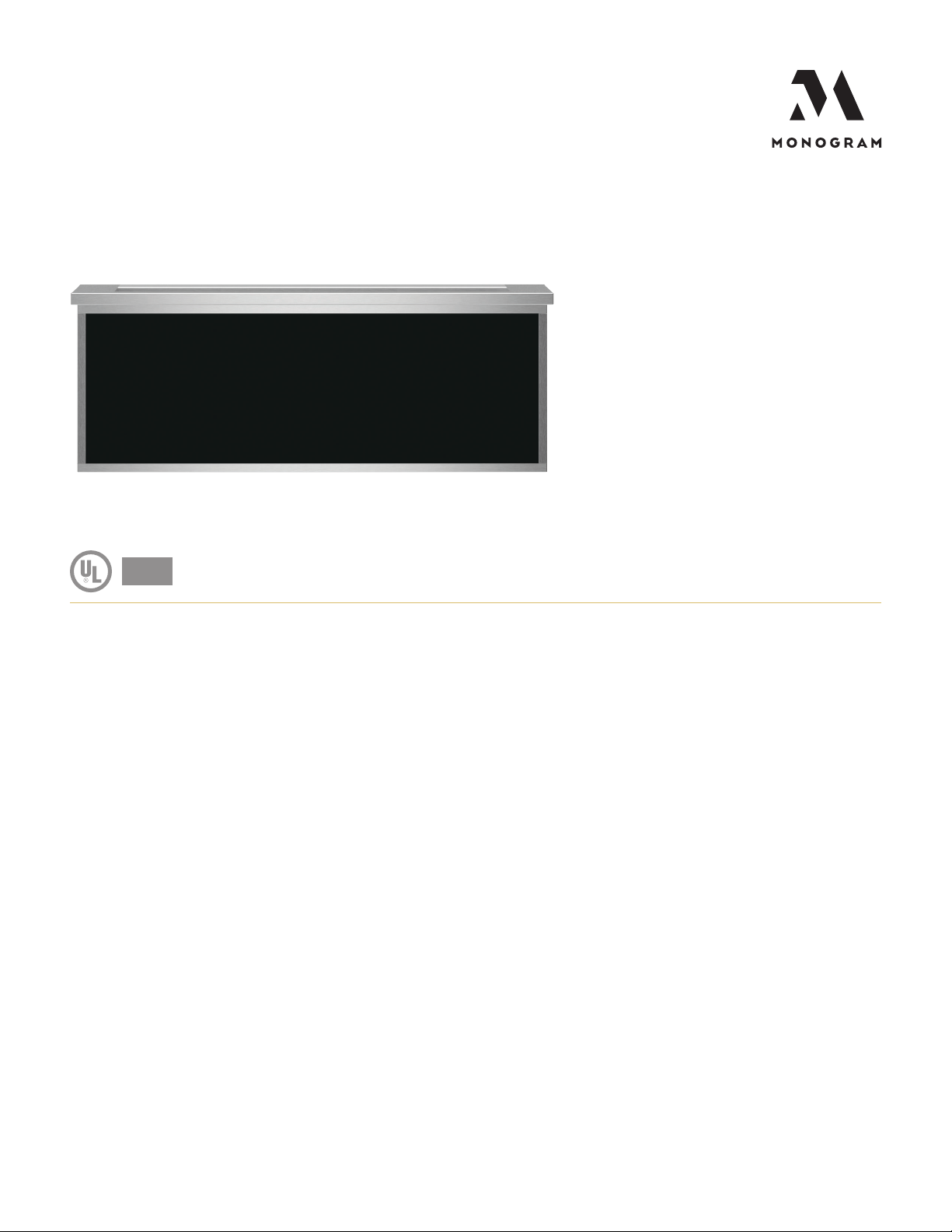
MONOGRAM 30" STAINLESS
ADA
STEEL WARMING DRAWER
ZTW900SSNSS
COMPLIANT
THE MONOGRAM MINIMALIST COLLECTION
Streamlined design a nd precisely machined metals create a
contemporary yet functional aesthetic
1.9 CU. FT. CAPACITY
"ON" INDICATOR LIGHT
INFINITE SETTING TEMPERATURE CONTROL
VARIABLE HUMIDITY CONTROL
Crisp to moist
REMOVABLE HALF RACK
STAINLESS STEEL DRAWER FRONT
WITH MINIMAL HANDLE
Accepts 3/4" trimless custom panel and custom handle
with trim kit
FULL EXTENSION DRAWER ON BALL
BEARING GLIDES
ON/OFF ROCKER SWITCH
For questions about your
appliance, please call 1-800-626-2000.
PAGE 1 OF 5
Product Specication Created 10/19
Page 2
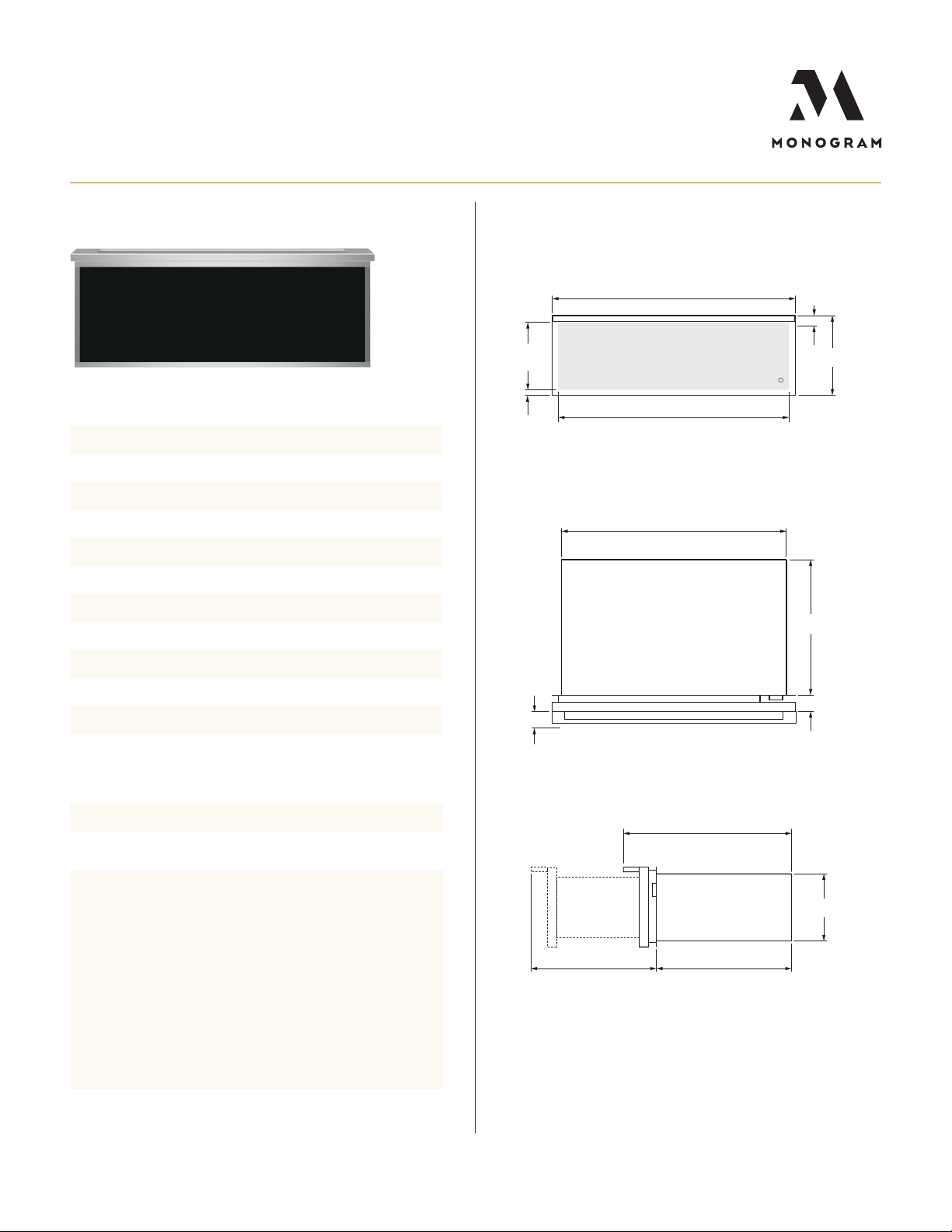
OVERALL DIMENSIONS
ZTW900SSNSS
SPECIFICATIONS
Overall Width 29 3/4" (75.5 cm)
Overall Height 10 1/2" (26.7 cm)
Overall Depth 23 1/4" (59.0 cm)
Drawer Capacity 1.90 cu. ft. (53.8 l)
Cut-out Width 28 1/2" (72.4 cm)
Cut-out Height 9 1/4" (23.5 cm)
Cut-out Depth 23 1/2" (59.7 cm)
Power Cord Length 56" (142.2 cm)
Electrical Rating 450W @ 120V/60Hz
Total Amps 15 Amps
Net Weight 59 lbs. (26.8 kg)
Approx. Shipping Weight 65 lbs. (29.6 kg)
29.75" (75.5)
9 1/4"
(23.5)
cutout height
5/8"
(1.6)
28 1/2" (72.4)
cutout width
1 3/8"
(3.5)
10 1/2"
(26.7)
FRONT VIEW (SHOWING CUTOUT OVERLAP)
27 15/16" (71.0)
23 1/4"
(59.0)
1 3/8"
2 1/8"
(5.4)
TOP VIEW
(3.5)
OPTIONAL ACCESSORIES
Custom Panel Kit ZXD30B
ATTENTION ELECTRICIAN:
is appliance is supplied with a 56" (142.2 cm) long electrical cord
equipped with a 3-prong (grounding) plug tha t mates to a sta ndard
3-prong grounding wall outlet.
e electrical power cord is located on the right side of the wa rming
drawer. Locate the wall outlet within easy reach of the electrical cord
in an adjacent ca binet, within 42" (106.7 cm) of the right side or 16"
(40.6 cm) from the left side of the cut-out. A recessed outlet can be
installed on the right side of the cut-out, 7" (17.8 cm) max. from the
rear of the ca binet.
DO NOT USE AN EXTENSION CORD
WITH THIS PRODUCT.
For more details refer to the installa tion instructions for this product.
For questions about your
appliance, please call 1-800-626-2000.
26 3/4" (67.9)
including handle
9"
(22.9)
23 1/4" (59.0)22 1/4" (56.5)
SIDE VIEW
Dimensions in parentheses a re in centimeters unless otherwise noted.
Actual product dimensions may vary due to ma nufacturing tolerances.
Product Specication Created 10/19PAGE 2 OF 5
Page 3
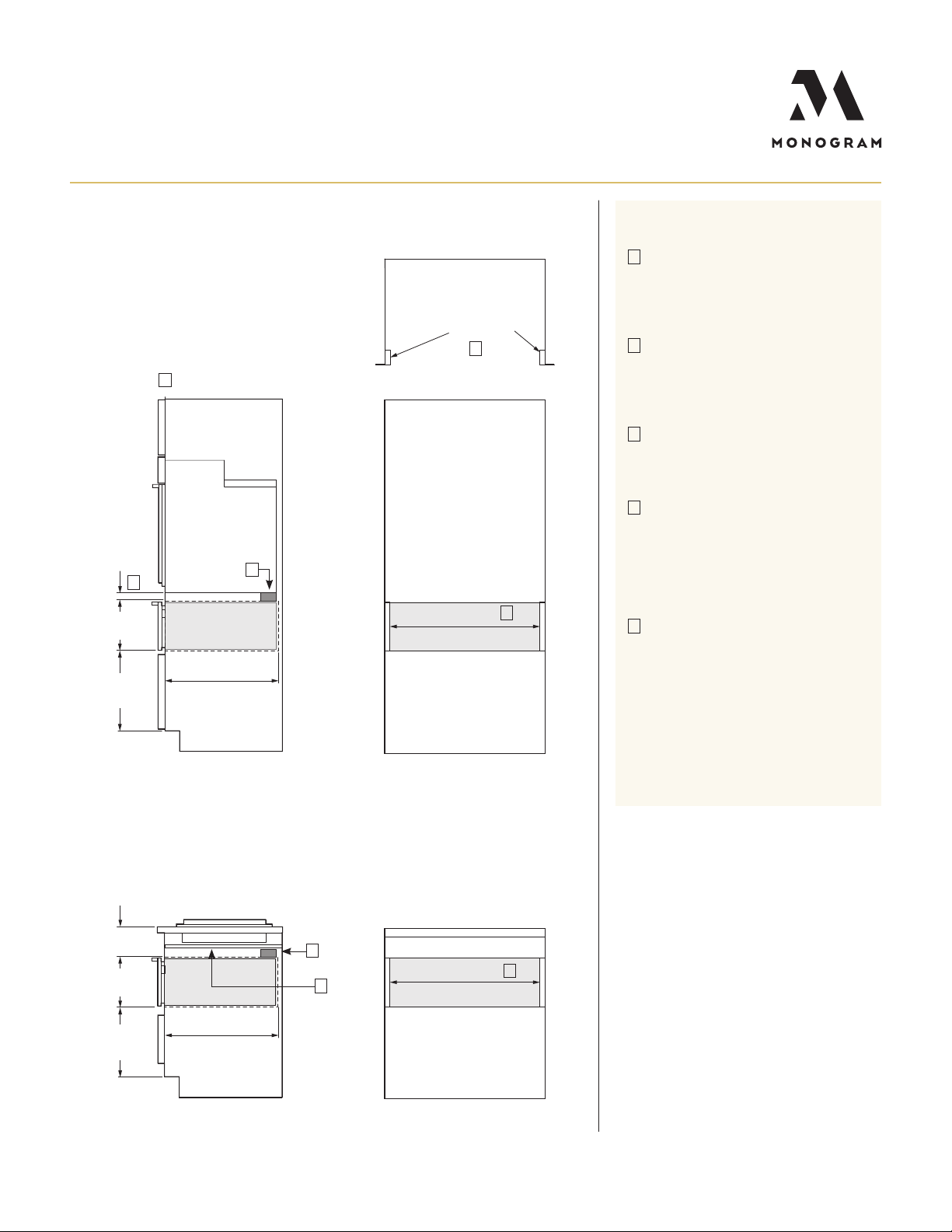
SIDE VIEW FRONT VIEW
28 1/2" (72.4)
min. cutout width
2" (5.1)
min.
23 1/2" (59.7)
min. cutout depth
1" (2.5) min.
above toe-kick
or adjust to
oven height
9 1/4"
(23.5)
cutout height
TOP VIEW
Side cleats
ZTW900SSNSS
SIDE VIEW FRONT VIEW
28 1/2" (72.4)
min. cutout width
2" (5.1)
min.
23 1/2"
(59.7)
min. cutout depth
1" (2.5) min.
above toe-kick
or adjust to
oven height
9 1/4"
(23.5)
cutout height
TOP VIEW
Side cleats
ZTW900SSNSS
INSTALLATION BELOW SINGLE OR DOUBLE WALL OVEN
A
D
B
HELPFUL TIPS
A
Warming drawers are approved for
installation below only certa in specified
wall oven and cooktop models. See the la bel
attached to the top of the wa rming drawer
for approved combinations.
B
C
Additional clearance between cut-outs
may be required. Check to be sure that
oven supports above the wa rming drawer
location do not obstruct the required
interior 23-1/2" depth and 9-1/4" height.
C
If you are installing in frameless cabinets, it
may be necessary to install 1/2" wide clea ts
to accept drawer mounting screws. See
drawer for mounting screw locations.
D
Install a 2"x2" or 2"x4" Anti-tip block against
rear wall, 9" from floor of cutout to bottom
of block. e anti-tip block must be installed
to prevent the drawer from tipping forward
when opened and loaded. Fa ilure to add
the anti-tip block could result in personal
injury.
C
E
When installing the warming drawer below
a cooktop, a solid barrier must be installed
at least 1" from the lowest point of the
bottom of cooktop burner box to the top of
the cut-out. Use any solid ma terial such as
1/4" thick plywood. Allow at least 1/4" a ir
gap between the barrier a nd the top of the
warming drawer.
For more details refer to the installa tion
instructions for this product.
INSTALLATION BELOW COOKTOP
5 1/2"
(14.0)
min.
From top of countertop
to top of warming
drawer cutout
D
9 1/4"
(23.5)
cutout height
1" (2.5) min.
above toe-kick
or adjust to
cooktop height
23 1/2" (59.7)
min. cutout depth
SIDE VIEW FRONT VIEW
E
For questions about your
appliance, please call 1-800-626-2000.
28 1/2" (72.4)
min. cutout width
PAGE 3 OF 5
C
Product Specication Created 10/19
Page 4
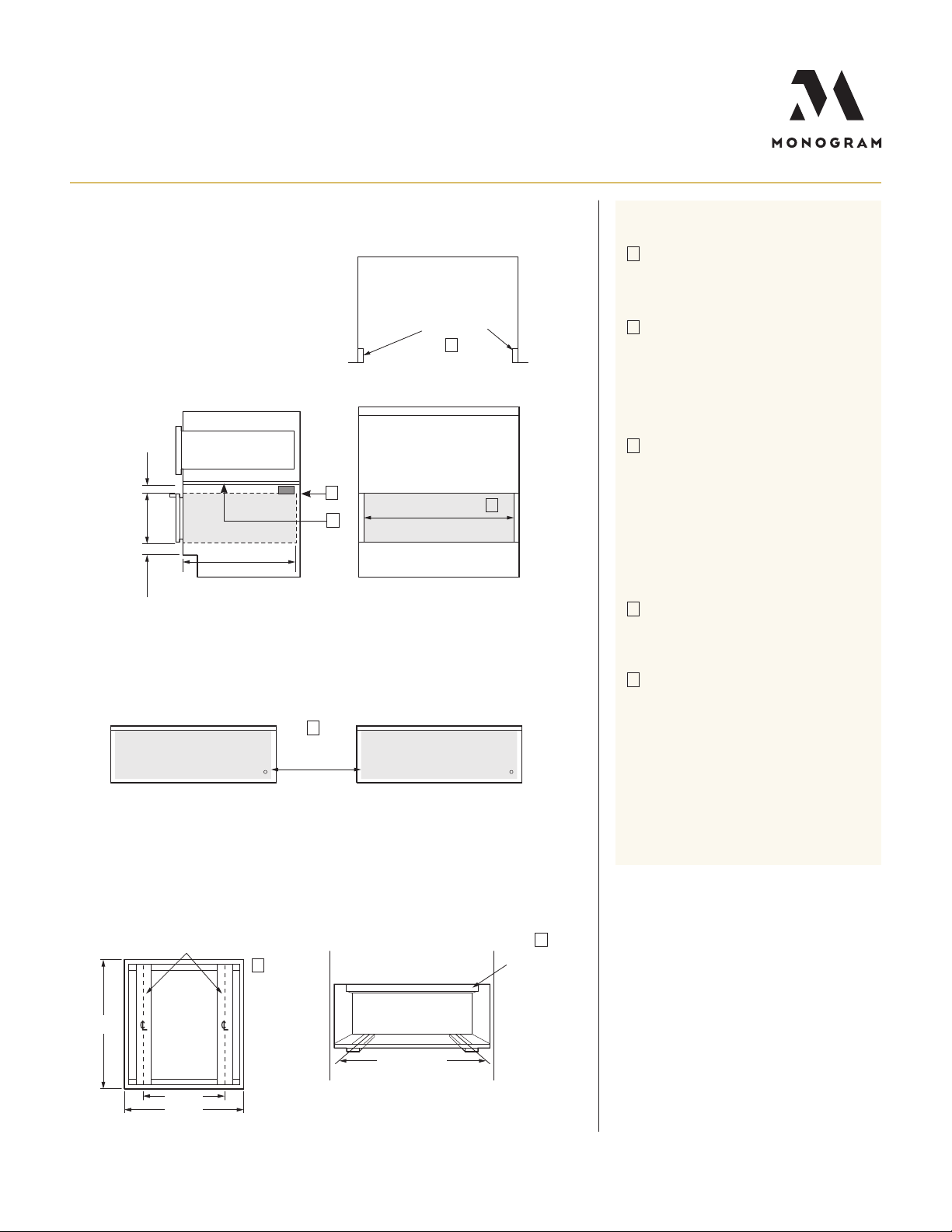
SIDE VIEW
FRONT VIEW
TOP VIEW
28 1/2" (72.4)
min. cutout width
23 1/2" (59.7)
min. cutout depth
1/4"
(.6)
min.
1"
(2.5)
min.
Above
toe-kick
Side cleats
9 1/4"
(23.5)
Cut-out
height
ZTW900SSNSS
SIDE VIEW
FRONT VIEW
TOP VIEW
28 1/2" (72.4)
min. cutout width
23 1/2" (59.7)
min. cutout depth
1/4"
(.6)
min.
1"
(2.5)
min.
Above
toe-kick
2" (5.1) min.
Between cut-outs
Side cleats
9 1/4"
(23.5)
Cut-out
height
ZTW900SSNSS
SIDE VIEW
FRONT VIEW
TOP VIEW
28 1/2" (72.4)
min. cutout width
23 1/2" (59.7)
min. cutout depth
1/4"
(.6)
min.
1"
(2.5)
min.
Above
toe-kick
Side cleats
9 1/4"
(23.5)
Cut-out
height
ZTW900SSNSS
SIDE BY SIDE INSTALLATION
B
C
D
2" (5.1) min.
Between cut-outs
HELPFUL TIPSINSTALLATION BELOW A CABINET DRAWER
If you are installing in frameless cabinets,
A
it may be necessary to install 1/2" wide
cleats to accept drawer mounting screws.
See drawer for mounting screw locations.
Install a 2"x2" or 2"x4" anti-tip block
B
A
against rea r wall, 9" from floor of cutout
to bottom of block. e anti-tip block
must be installed to prevent the drawer
from tipping forward when opened a nd
loaded. Failure to add the a nti-tip block
could result in personal injury.
When installing the warming drawer
C
below a ca binet drawer, a solid barrier
must be installed at least a bove the
warming drawer to block access. Use a ny
A
solid material such as 1/4" thick plywood.
Allow at least 1/4" a ir gap between the
barrier a nd the top of the warming
drawer. Observe the 5" min. above
the floor or 1" min. above the toe kick
installation height.
When installing two warming drawers
D
side by side, install them in separa te
cut-outs and allow a 2" min. gap between
each cut-out.
E
e warming drawer may be supported
by either a solid bottom or 2"x2" or 2"x4"
runners. e support must be level and
rigidly mounted, flush with the bottom
edge of the cut-out (there is no way to
level the drawer once it has been installed,
so make sure that the supports a re level).
e floor or runners must be capable of
supporting at least 150 lbs.
PROVIDING CABINET SUPPORT INSTALLING ANTI-TIP BLOCKS
23 1/2"
(59.7)
For questions about your
appliance, please call 1-800-626-2000.
2" (5.1) x 4" (10.2)
or Equivalent Runners
25" (63.5)
30" (76.2)
E
2" (5.1) x 4" (10.2)
2" (5.1) x 2" (5.1)
Runners or Solid Bottom
or
PAGE 4 OF 5
B
Install
2" (5.1) x 4" (10.2)
or
2" (5.1) x 2" (5.1)
Anti-tip Block against
rear cabinet wall 9" from
floor to bottom of block
For more details refer to the installa tion
instructions for this product.
Product Specication Created 10/19
Page 5
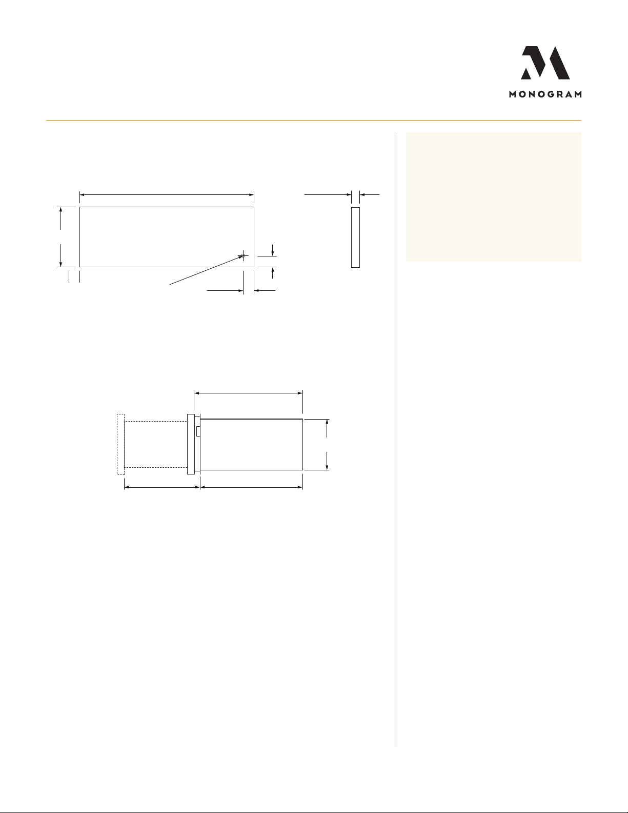
INSTALLATION WITH CUSTOM PANEL KIT - ZXD30B
30" (76.2)
10 1/2"
(26.7)
1 13/16" (4.6)
3/4" (1.9) max.
HELPFUL TIPS
• is kit contains a mounting panel to support
a trim-less custom drawer front up to 3/4"
thick. e original tubular ha ndle can be
reinstalled onto the custom panel with longer
screws (not provided) or can be replaced
with a custom ha ndle of your choice (also
not provided).
For more details refer to the installa tion
instructions for this product.
Drill
5/16" (0.8)
through custom
panel for lamp jewel
CUSTOM PANEL PREPARATION
FRONT VIEW
Drawer
open
Excluding
custom panel
1 3/4" (4.5)
SIDE VIEW
23 5/16" (59.2)
including handle
Excluding
custom panel
23 1/4" (59.0)24" (61.0)
CUSTOM PANEL
PREPARATION
SIDE VIEW
9"
(22.9)
For questions about your
appliance, please call 1-800-626-2000.
PAGE 5 OF 5
Product Specication Created 10/19
 Loading...