

Page 1
GE Monogram ®
Installation
Instructions
Stainless Steel
Built-In
Refrigerators
Models
ZISS3b'D SS, ZISS3b'N SS
ZISS42D SS, ZISS42N SS
ZISS48D SS, ZISS48N SS
Page 2
Contents
Before you begin - Read these instructions completely and carefully.
IMPORTANT - Save these instructions for local inspector's use.
IMPORTANT- OBSERVE ALL GOVERNING CODES AND ORDINANCES.
Note to Installer - Be sure to leave these instructions with the Consumer.
Note to Consumer - Keep these instructions with your Use and Care Book for future reference.
fl?11? This appliance must be properly grounded. See "Grounding the Refrigerator," page 6. I
Cet appareil doit 6tre correctement mis _ la terre.
Consulter <<Mise _ terre du r6frig6rateur >_,page 6.
If you have a question concerning the installa-
tion of this product, call the GE Answer
Center :'_Consumer Information Service at
800.626.2000, 24 hours a day, 7 days a week.
If you received a damaged refrigerator, you
should immediately contact your dealer or
builder
Proper installation is the responsibility of the
installer. Product failure due to improper
installation is not covered under the GE
Appliance Warranty. See the Use & Care
Guide for warranty information.
For Monogram local service in your area,
1-800-444-1845.
For Monogram Service in Canada,
1-800-880-3030.
For Monogram Parts and Accessories, call
1-800-626-2002.
Design Information
Flush or Semi-Flush Enclosure Installations ................................................................................... 3
Enclosure Cutout and Product Dimensions ................................................................................... 3
Installation Examples ........................................................................................................................ 4
Installation Preparation
Product Dimensions & Clearances .................................................................................................. 5
Water Connection Location, Electrical ........................................................................................... 5
Accessories ......................................................................................................................................... 5
Grounding the Refrigerator ............................................................................................................. 6
Tools Required .................................................................................................................................. 7
Materials Required ............................................................................................................................ 7
Hardware Supplied ........................................................................................................................... 7
Optional Hardware ........................................................................................................................... 7
Flooring .............................................................................................................................................. 7
Step 1: Remove Packaging ................................................................................................................ 7
Installation Instructions
Step 2: Install Water Line ................................................................................................................. 8
Step 3: Install Side Panels ................................................................................................................ 9
Step 4: Roll Refrigerator into Opening ........................................................................................... 9
Step 5: Level Refrigerator ............................................................................................................... 10
Step 6: Secure Refrigerator Case Trim to Side Panels ................................................................. 10
Step 7: Connect Water Supply ........................................................................................................ 11
Step 8: Connect Power .................................................................................................................... 11
Step 9: Mount Top Grill Panel ....................................................................................................... 11
Step 10: Arrange Interior ............................................................................................................... 12
Step 11: Set Temperature Controls ................................................................................................ 12
Step 12: Start Icemaker ................................................................................................................... 12
Step 13: Install Toekick ................................................................................................................... 13
Problem Solving .............................................................................................................................. 15
• Use this appliance only for its intended
purpose.
• Immediately repair or replace electric service
cords that have become flayed or damaged.
• Unplug the refrigerator before cleaning or
making repairs.
• Repairs should be made by a qualified service
technician.
• I1 ne faut utiliser cet appareil que pour l'usage
pour lequel il a _t_ construit.
• I1 faut r_parer ou remplacer imm_diatement
tout cordon d'alimentation _lectrique
effiloch_ ou endommag_.
• D_brancher le r_ffig_rateur avant le nettoyage
ou route intervention.
• Les r_parations doivent _tre faites par un
technicien qualifi_.
Page 3
Design Information
Flush or
Semi-Flush
Enclosure
Installations
Advance Planning
I
i
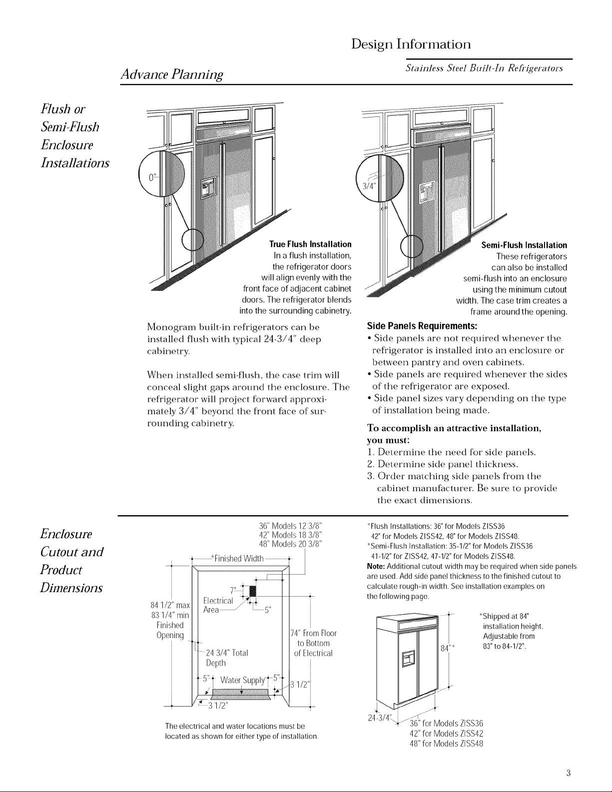
True Flush Installation
In a flush installation,
the refrigerator doors
will align evenly with the
front face of adjacent cabinet
doors. The refrigerator blends
into the surrounding cabinetry.
Monogram built-in refrigerators can be
installed flush with typical 24-3/4" deep
cabinetry.
When installed semi-flush, the case trim will
conceal slight gaps around the enclosure. The
refrigerator will project forward approxi-
mately 3/4" beyond the front face of sur-
rounding cabinetry.
Stainless Steel Built-In Refrigerators
Semi-Flush Installation
These refrigerators
can also be installed
semi-flush into an enclosure
using the minimum cutout
width. The case trim creates a
frame around the opening.
Side PanelsRequirements:
• Side panels are not required whenever the
refrigerator is installed into an enclosure or
between pantry and oven cabinets.
• Side panels are required whenever the sides
of the refrigerator are exposed.
• Side panel sizes vary depending on the type
of installation being made.
To accomplish an attractive installation,
you must:
1. Determine the need for side panels.
2. Determine side panel thickness.
3. Order matching side panels from the
cabinet manufacturer. Be sure to provide
the exact dimensions.
Enclosure
Cutout and
Product
Dimensions
36" Models 12 3/8"
42" Models 18 3/8"
48" Models 20 3/8"
, ¢Finished Width
84 1/2" max Electrical _ ,,
83 1/4" min ]I Area / 5
Finished II
Opening tit
lit 24 3/4" Total
II Depth
_t 5"1 Water Supply i 5't
_Y ; 3 1/2"
The electrical and water locations must be
located as shown for either type of installation.
/
74"FromFloor
to Bottom
of Electrical
1/2'i
*Flush Installations: 36" for Models ZLSS36
42" for Models ZLSS42, 48" for Models ZLSS48.
*Semi-Flush Installation: 35-1/2" for Models ZISS36
41-1/2" for ZISS42, 47-1/2" for Models ZISS48.
Note: Additional cutout width may be required when side panels
are used. Add side panel thickness to the finished cutout to
calculate rough-in width. See installation examples on
the following page.
*Shipped at 84"
installation height.
Adjustable from
83"to 84-1/2".
24-3/4'L
36"for ModelsZISS36
42"for ModelsZISS42
48"for ModelsZISS48
Page 4
Design Information
Stainless Steel Built-In Refrigerators
Installation
Between
Base c_
Wall Cabinets
Installation
At End-of-Run
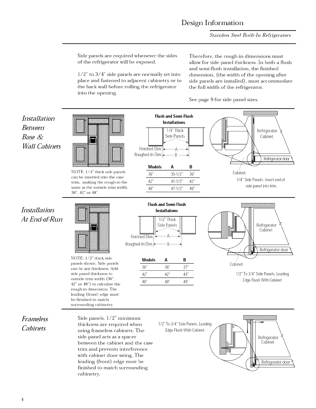
Side panels are required whenever the sides
of the refrigerator will be exposed.
1/2" to 3/4" side panels are normally set into
place and fastened to adjacent cabinetry or to
the back wall before rolling the refl'igerator
into the opening.
Flushand Semi-Flush
I IISidePanels II I
Finished Dim, I_A_
Roughed-In Dim,_B
Models A B
NOTE: 1/4" thick side panels
can be inserted into the case
trim, making the rough in the
same as the outside trim width,
36", 42" or 48".
Finished Dim, I_, A_-I
Roughed-In Dim,_B_
NOTE: 1/2" thick side
panels shown. Side panels
can be any thickness. Add
side panel thickness to
outside trim width (36",
42" or 48") to calculate the
rough in dimension. The
leading (front) edge nmst
be finished to match
surrounding cabinetry.
36" 35-1/2" 36" Cabinet
42" 41-1/2" 42"
48" 47-1/2" 48"
Flushand Semi-Flush
Installations
1/2" Thick
IISideoPanelsII I
[_lJ" ..... _ll I
Models A B
36" 36" 37"
42" 42" 43"
48" 48" 49"
Installations
1/4" Thick
jjJ - ._
Therefore, the rough-in dimensions must
allow for side panel thickness. In both a flush
and semi-flush installation, the finished
dimension, (the width of the opening after
side panels are installed), must accommodate
the full width of the refrigerator
See page 9 for side panel sizes.
!i) Refrigerat°r_
Cabinet
/
/
1/4" Side Panels,Insertend of
side panel into trim
Refrigeratordoor
Refrigerator'_
\ Cabinetk
i_, Refrigeratordoor\
/
Cabinet
1/2" To 3/4" SidePanels,Leading
EdgeFlush With Cabinet
Frameless
Cabinets
Side panels, 1/2" minimum
thickness are required when
using frameless cabinets. The
side panel acts as a spacer
between the cabinet and the case
trim and prevents interference
with cabinet door swing. The
leading (front) edge must be
finished to match surrounding
cabinetry.
1/2" To 3/4" SidePanels,Leading
EdgeFlush With Cabinet /
erator
Page 5
Installation Preparation
Stainless Steel Built-In Refrigerators
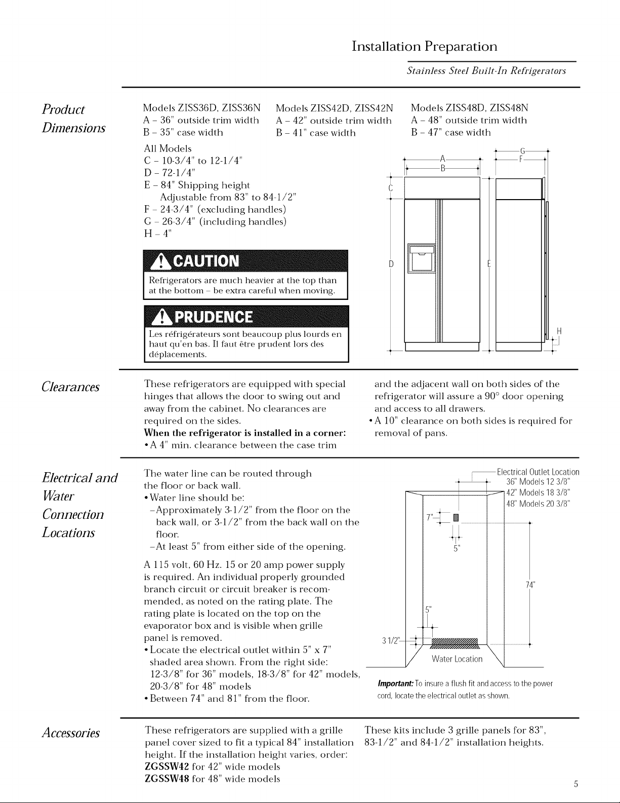
Product
Dimensions
Clearances
Models ZISS36D, ZISS36N Models ZISS42D, ZISS42N
A - 36" outside trim width A - 42" outside trim width
B - 35" case width B - 41" case width
All Models
C - 10-3/4" to 12-1/4"
D - 72-1/4"
E - 84" Shipping height
Adjustable from 83" to 84-1/2"
F - 24-3/4" (excluding handles)
G - 26-3/4" (including handles)
H-4"
Refrigerators are much heavier at the top than
at the bottom be extra careflfl when moving.
Les r_frig_rateurs sont beaucoup plus lourds en
haut qu'en bas. I1 faut _tre prudent lors des
d_placements.
These refrigerators are equipped with special
hinges that allows the door to swing out and
away from the cabinet. No clearances are
required on the sides.
When the refrigerator is installed in a corner:
* A 4" min. clearance between the case trim
and the adjacent wall on both sides of the
refrigerator will assure a 90 ° door opening
and access to all drawers.
• A 10" clearance on both sides is required for
removal of pans.
Models ZISS48D, ZISS48N
A - 48" outside trim width
B - 47" case width
T
C
_G
_F_
I
Electrical and
Water
Connection
Locations
Accessories
The water line can be routed through
the floor or back wall.
• Water line should be:
-Approximately 3-1/2" from the floor on the
back wall, or 3-1/2" from the back wall on the
floor.
-At least 5" from either side of the opening.
A 115 volt, 60 Hz. 15 or 20 amp power supply
is required. An individual properly grounded
branch circuit or circuit breaker is recom-
mended, as noted on the rating plate. The
rating plate is located on the top on the
evaporator box and is visible when grille
panel is removed.
• Locate the electrical outlet within 5" x 7"
shaded area shown. From the right side:
12-3/8" for 36" models, 18-3/8" for 42" models,
20-3/8" for 48" models
• Between 74" and 81" from the floor.
These refrigerators are supplied with a grille
panel cover sized to fit a typical 84" installation
height. If the installation height varies, order:
ZGSSW42 for 42" wide models
ZGSSW48 for 48" wide models
-- ElectricalOutletLocation
36"Models123/8"
42"Models183/8"
48"Models203/8"
74"
31/2'_
Water Location \
Important:To insurea flush fit and accessto the power
cord, locate the electrical outlet as shown,
These kits include 3 grille panels for 83",
83-1/2" and 84-1/2" installation heights.
Page 6

Installation Preparation
Stainless Steel Built-In Refrigerators
Grounding
the
Refrigerator
IMPORTANT- (Please read careflflly)
FOR PERSONAL SAFETY, THIS APPLI-
ANCE MUST BE PROPERLY GROUNDED.
The power cord of this appliance is equipped
with a three-prong (grounding) plug which
mates with a standard three-prong (ground-
ing) wall receptacle to minimize the possibil-
ity of electric shock hazard from this appli-
ance.
Have the wall outlet and circuit checked by a
qualified electrician to make sure the outlet
is properly grounded.
Where a standard 2-prong wall outlet is
encountered, it is your personal responsibil-
ity and obligation to have it replaced with a
properly grounded 3-prong wall outlet.
Use of Adapter plug
Because of potential hazards under certain
conditions, we strongly recommend against
use of an adapter plug. However, if you still
elect to use an adapter, where local codes
permit, a TEMPORARY CONNECTION, may
be made to a properly grounded 2-prong wall
outlet by use of a UL listed adapter available
at most hardware stores.
The larger slot in the adapter must be
aligned with the larger slot in the wall outlet
to provide proper polarity in the connection
of the power cord.
Attaching the adapter ground terminal to
a wall outlet cover screw does not ground
the appliance unless the cover screw is
metal, and not insulated, and the wall
outlet is grounded through the house
wiring. You should have the circuit
checked by a qualified electrician to make
sure the outlet is properly grounded.
DO NOT, UNDER ANY CIRCUMSTANCES,
CUT OR REMOVE THE THIRD (GROUND)
PRONG FROM THE POWER CORD.
When disconnecting the power cord from
the adapter, always hold the adapter in place
with one hand and pulling the power cord
with the other hand. If this is not done, the
adapter ground terminal is very likely to
break with repeated use.
Should the adapter ground terminal break,
DO NOT USE the appliance until a proper
ground has again been established.
Use of Extension Cords
Because of potential safety hazards under
certain conditions, we strongly recommend
against the use of an extension cord. How-
ever, if you still elect to use an extension
cord, it is absolutely necessary that it be a UL
listed 3-wire grounding type appliance
extension cord having a grounding type plug
and outlet and that the electrical rating of
the cord be 15 amperes (minimum) and
120 volts.
FICHE D'ADAPTATION
(Fiches d'adaptation non permises au
Canada)
Page 7

Installation Preparation
Stainless Steel Built-In Refrigerators
Tools
Required
Materials
• Tinsnips to cut banding
• Stepladder
• Bucket
• Level
• 1-1/2" open-end wrench
• Side panels to match cabinetry
• 2x4, 36", 42" or 48" long, for Anti-Tip support, see page 10
Required
Hardware
Supplied
• Special velcro adhesive strips for 1/4" side panels
• 1/4-1/4 union with nuts
• Water filter bypass plug
Hardware • Water shut-off valve
Recommendations
Flooring
For proper installation, this refrigerator must
be placed on a level surface of hard material
that is at the same height as the rest of the
flooring. This surface should be strong
enough to support a fully loaded refrigerator
• Appliance Hand Truck
• Tubing cutter
• 7/16" open-end wrench
• #2 Phillips screwdriver
• Stubby Phillips screwdriver
NOTE: Protect the finish of the flooring. Cut
a large section of the cardboard carton and
place under the refrigerator where you are
working.
• Drill and appropriate bits
• 7/16" socket with 3" extension
for ratchet
• Safety glasses
SteI1
melllOVe
Packaging
Refrigerator is much heavier at the top than at
the bottom be careflfl when moving. When
using a hand truck, handle from side only.
Le r_ffig_rateur est beaucoup plus lourd en
haut qu'en bas. I1 faut 6tre prudent lots des
d6_placements. Si un diable est utilis_, il faut
soulever le r_frig_rateur sur le c6t_ seulement.
• Remove outer carton.
-Careflflly cut banding at the top and
bottom.
° Slide out back corner posts (2).
° Slide carton off top of cabinet.
NOTE: IT IS NOT NECESSARY TO LAY
CABINET DOWN IN ORDER TO REMOVE
SKID!
° To remove skid, remove the four 7/16" bolts
and their brackets.
° There are support blocks on the bottom of
the cabinet and door: They must be removed
before sliding unit off skid or damage will
OCCtlF,
• Careflflly, tilt cabinet and slide blocks out
from beneath cabinet, slide unit off skid.
° Remove toekick from the fresh food com-
partment, set aside for later installation.
7/16" Bolt
,/
f
f
DO NOT ATTEMPT TO ROLL UNIT OFF
SKID.
IL NE FAUT PAS ESSAYERDE FAIRE
ROULER LE Rt_FRIGt_RATEURPOUR
L'ENLEVER DE LAYPALETTE.
Page 8

Install
Water
Line
Installation
= 11
When connecting a GE Reverse
Osmosis Water System to your
refrigerator, the only approved
installation is with a GE RVKIT.
If the water supply to the refrigera-
tor is from a Reverse Osmosis Water
System AND the refrigerator also has
a water filter, use the refrigerator's
filter bypass plug. Using the
refrigerator's water filtration
cartridge in conjunction with the
RO filter can result in hollow ice
cubes and slower water flow from the
water dispenser.
If you use the bypass Plug and want a light shield without
the filter opening, order a replacement solid light shield:
For 36" Models Order WR17X3025
For 42" Models Order WR02X8967
For 48" Models Order WR17X3433
To Remove
Stainless Steel Built-In Refrigerators
-V
Lors du raccordement au r_frig_rateur
du syst_me GE de purification de l'eau
par osmose inverse.e, seule l'installation
avec un ensemble GE RVKIT est
approuv_e.
Si le r_frig_.rateur es aliment6_ en eau
partir d'un syst_me de filtration d'eau par
osmose invers_e, et si le r_frig_rateur
comporte _galement un filtre a eau,
utiliser le bouchon du circuit de
d_rivation du filtre du r_frig_rateur. Si la
cartouche de filtration d'eau du
r_frig_rateur est utilis_e en conjonction
avec le syst_me de filtration par osmose
invers_e, on peut observer une r_duction
du d_bit d'eau au point de puisage, et la
production de cubes de glace creux.
• A cold water supply is required for automatic
icemaker operation. The water pressure
must be between 40 and 120 p.s.i.
• Route 1/4" OD copper tubing between
house cold water line and the water connec-
tion location.
• Copper tubing should be long enough to
extend to the front of the refrigerator. Allow
enough to accommodate bend leading into
the water valve.
Shut off the main water supply.
Turn on the nearest faucet long enough to
clear the line of water.
Install a shut-off valve between the icemaker
water valve and cold water pipe in a basement
or cabinet. The shut-off valve should be
located where it will be easily accessible.
NOTE: It is best to install the valve into a
vertical water pipe. If you install the valve into
a horizontal water pipe, make the connection
at the top or side, rather than at the bottom,
to avoid drawing off any sediment from the
water pipe.
• Drill a 1/4" hole in the water pipe.
• Fasten the shut-off valve to the pipe with
pipe clamp.
• Tighten the clamp screws until the sealing
washer begins to swell. Do not over tighten.
"Place a compression nut and ferrule (sleeve)
onto the end of the tubing and connect it to
the shut-off valve. Make sure the tubing is
flflly inserted into the valve and ferrule is
tightened.
° Floor_
CopperTubing4
Washer
SaddleType
Inlet End
Shuto?ve_
Pipe Clamp
Packin_
Outlet Valve
Compression Nut
/
\
Ferrule
(Sleeve)
• Turn on the main water supply and flush
debris from the line. Run about a quart of
water through the tubing into a bucket. Shut
off water supply at the shut-off valve.
NOTE: Saddle type shut-off valves are in-
cluded in many water supply kits. Before
purchasing, make sure a saddle type valve
complies with your local plumbing codes.
NOTE: Commonwealth of Massachusetts
Plumbing Codes 248CMR shall be adhered
to. Saddle valves are illegal and use is not
permitted in Massachusetts. Consult with
your licensed plumber.
Page 9

Installation
Stainless Steel Built-In Refrigerators
Install
Side
Panels
• Side panels are required whenever the sides
of the refrigerator will be exposed and when
installed between frameless cabinets. See
pages 3 and 4.
• Side panels are not required when the
refrigerator is installed into an enclosure.
• Side panel installation will be determined by
the design of the side panel you have previ-
ously chosen.
• Side panels must be installed plumb.
Illustration/z,
1/4" Side Panels-
Insertendof side
panel into case trim,
Fastenwith Velcro
strips included,
TopView
Standard 4" high toekick or trim to fit, Height
mayvary dependingon application,
Illustration C
1/2" to 3/4" Side
Panels- Recessed
front edge of side
panel, Fastento
adjacent cabinet,
23-9/16"
84"
2-9/16"
234/16"
ill .................t
84"
• If you choose to use 1/4" side panels, they
should be inserted into the case trim as
illustrated. Fasten the panels to the refrigera-
tor with velcro strips (provided) before setting
refrigerator in place. See illustration A.
° 1/2" to 3/4" side panels are normally set into
place and fastened to adjacent cabinetry or
the back wall before rolling the refrigerator
into the opening. See illustrations B and C.
Illustration B
1/2" to 3/4" Side
Panels- Leading
edgeof sidepanel is
flushwith cabinet
front, Fastento the
backwall usinga
cleat,
24-3/4"
) 3-3/4"
Top View
Standard 4" high toekick or trim to fit,
Height mayvary depending on application,
Roll
Refrigerator
Into Opening
@
Top View
Standard 4" high toekick or trim to fit,
Height mayvary depending on application,
2 5/16
• The cardboard protective pad should be
beneath the refrigerator.
° Gently push refrigerator into opening with
hands against front corners.
° Roll refrigerator into the opening until it is
flush with adjacent cabinets.
Page 10

Level
Refrigerator
SteI6
Secure
Refrigerator
Case Trim,
to Side Panel
All models have 4-point leveling. The front is
supported by leveling legs, the rear is
supported by wheels.
• To level the back of the refrigerator,
turn the 7/16" hex nut located above the
front wheels. Turn to raise or lower the
refrigerator.
° For front leveling, use a 1-1/2" open-end
wrench.
• Adjust carefully, the refrigerator should be
level and plumb with cabinetry, and should
align with toekick height.
ANTI-TIP PRECAUTIONS
The refrigerator is heavy at the top and must be
secured to prevent the possibility of tipping
forward.
PRECAUTIONS CONTRE LES
BASCULEMENTS
Le r_frig6_rateur est beaucoup plus lourd en
haut et il faut le maintenir en place pour 6_viter
la possibilit6_ de son basculement vers l'avant.
Installation
Stainless Steel Built-In Refrigerators
HexNut
RearWheels
Block.....
OPTION 1
To prevent the refrigerator from tipping
over, you must:
• Install a wood block, the full width of the
refrigerator. Secure the block with wood
screws penetrating at least 3/4" into wall
studs.
OPTION 2
When using 1/2" to 3/4" side panels, the
front flange of the case trim should be
attached to the side panel.
• Open freezer door to access case trim.
• Drill hole in flange and drive screw
through the flange, into the side panel.
Follow the same procedure on the fresh
food side.
OR
If refrigerator is installed between cabinets
with no side panels or in a custom enclosure,
install a spacer block as shown.
• Open freezer door to access case trim.
• Drill hole in trim and drive screw through
the trim and into the spacer block.
• Follow the same procedure for fresh food
side.
SideView
m
Stud_Rerrigerator Cabinet_
SideView
10
Page 11

st7
Connect
Water
Supply
SteI 8
Connect
Installation
Stainless Steel Built-In Refrigerators
Check to be sure that refrigerator power cord
is not plugged into the wall outlet.
• Locate and bring copper tubing to the front
of the cabinet.
• The copper tubing should be just long
enough to reach the coupling. Excess tubing
length could interfer with door closing or
toekick installation.
• Slip a 1/4-1/4 union nut (provided) over
both ends of the copper tubing at the right
front leg of the refrigerator and couple the
lines.
• Turn on the water to check for leaks.
° Connect the refrigerator power cord plug
to properly grounded receptacle, accessible
through the top right side of the hood
opening.
Power
SteI9
Mount
Top Grille
Pand
The matching grille panel is sized for an
84" installation height.
° The refrigerator is shipped with the top
case trim secured at 84" installation height.
To raise or lower case trim to other installa-
tion heights:
° Loosen 2 screws on both sides and raise the
case trim to meet soffit height or to the top
of adjacent cabinets.
° Tighten all 4 screws.
° Mount the grille panel by dropping into
slots on the case trim.
If installation height is more or less than 84",
order ZGSSW42 or ZGSSW48 optional grille
panel kit which accommodates 83", 83-1/2"
and 84-1/2" heights.
TopCase Trim
RaiseToI
Installation
Height
1-1/2"
min,
gap
/
(
,\
\
/
/
.7
j-
/
J
/
Important: Maintain 1-1/2" min,gap between top of
doors and bottom of grille panel,
11
Page 12

Arrange
Interior
Installation
Stainless Steel Built-In Refrigerators
• Remove internal packing materials.
• The freezer compartment shelves are turned
upside down for shipping. They must be
removed and turned right side up. To
remove shelf packing, apply upward pressure
on the inverted shelf with one hand and hold
in place. Remove packing with other hand.
Grip shelf with both hands, lower shelf front
and remove from cabinet. Turn shelf right
side up and install in desired location.
• In the fresh food section, remove packing on
each side of shelves.
° Remove tape from all shelves.
° Set Fresh Food control at "5".
° Set Freezer control at "5".
Temperature
Controls
Start
Icemaker
IMPORTANT: Allow 24 hours for tempera-
tures to stabilize before making adjustments.
° Lower the feeler arm to the ON position
and the icemaker will begin operation
automatically.
• Discard the first few batches of ice cubes to
be sure that any remaining impurities in the
water line will be flushed out.
NOTE: During operation, you will hear the
hum of the motor, movement of the cube
ejector, humming or clicking of the water
valve, and ice falling into the bin. These
sounds are normal.
n
It
12
Page 13

Installation
Stainless Steel Built-In Refrigerators
Install
Toekick
• A standard toekick is supplied. Install with 2
screws provided, adjust to desired height and
tighten screws.
°A custom toekick can be installed to match or
complement the surrounding cabinetry.
°A standard toekick is supplied with all
models. If a custom toekick is to be installed,
use the supplied toekick as a template to cut
out notches around hinges and waterline
tubing.
°For 1/2" to 3/4" thick custom toekicks,
additional material should be removed and
cut away. This will allow the water and
electrical umbilical tube to rotate smoothly
when the door is fully opened.
StandardToekick(Packedwith Product)
L
1/4"ThickCustomToekick
D
1/2"to3/4"ThickCustomToekickRemoveAdditionalMaterial
13
Page 14

14
Page 15

Installation
Stainless Steel Built-In Refrigerators
Problem
Solving
Alignment of doors
Door alignment is usually assured when the
refrigerator is leveled. If doors are not aligned
after leveling the unit, call for service.
Operation of Refrigerator
If the refrigerator does not operate after
checking the installation instructions:
• Check to be sure power cord is plugged in
the wall outlet.
• Check to be sure that fuse or circuit breaker
is turned on.
If any of these problems persist:
Call for Monogram local service in your area,
1-800-444-1845.
In Canada, call 1-888-880-3030.
Cleaning the Stainless Steel Refrigerator
Stainless Steel has some unique cleaning
characteristics. In order to keep your
refrigerator looking like new, we suggest
cleaning it with Stainless Steel Magic or a
similar product.
Stainless Steel Magic is available at Ace, True
Value, Home Depot, Servistar, HWI and other
leading stores. It is also available through GE
Parts by calling 1-800-626-2002. Order part
number WX 10X 15.
15
Page 16

Monogram;
General Electric Company
Louisville, KY40225
Note: While performing installations described in this book,
safety glasses or goggles should be worn.
To obtain specific information concerning any
MonoglT_m product o1"service, call GE Answer Center _'
consumer #1formation service at 800.626.2000--any
dme, ct:_y o1"night.
For Monogram loc:_l service m yo_u are:_, c:_fi
1 800 444 1845.
NOTE: Product improvement is a continuing endeavor at General
Electric. Theaefoae, materials_ appearance and specifications are subject
to change without notice.
Pub. No. 49 60060 1
Dwg. No. 197r)1310PO02
¢) 1999 GE Appliances
(N.r). 459A) 12/99
70602 04
 Loading...