

Page 1
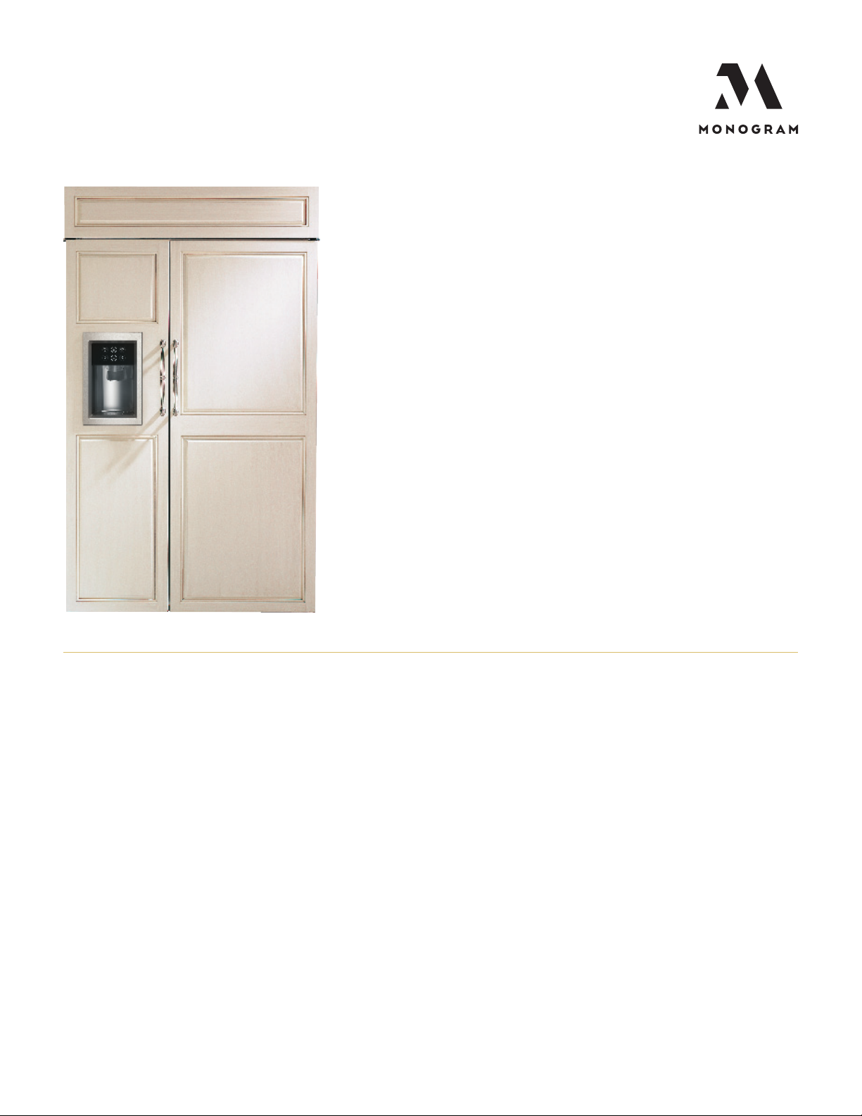
MONOGRAM 48" BUILT-IN
SIDE-BY-SIDE REFRIGERATOR
ZISB480DN
WIFI CONNECT
Enjoy the convenience and freedom of wirelessly controlling
functions from your smartphone
LED LIGHTING
Light columns in the freezer and fresh food compa rtments
extend the full length of the interior and LED lighting loca ted
inside the vegetable a nd climate-control drawers illumina te
contents without compromising space
COLOR-MATCHED DISPENSER WITH
PROXIMITY SENSOR
Designed to accommodate glasswa re of all sizes, from pitchers
to tumblers; control graphics light up as you approach and
automa tically switch off when
GE® WATER FILTER
Has been moved from the fresh food compartment to
the overhead cabinet, where it is discreetly out of sight
DELI DRAWER ON FULL-EXTENSION SLIDES
Keeps meats, cheeses a nd other everyday foods within easy reach
For questions about your
appliance, please call 1-800-626-2000.
SEALED VEGETABLE DRAWER
Helps preserve the freshness of foods
ADJUSTABLE GLASS SHELVES
Easily accommodate pa rty trays and pla tters
GALLON-SIZE DOOR BIN
Holds milk containers, two-liter bottles a nd pitchers
ADJUSTABLE DOOR BINS
Can be moved to one of two positions in seven loca tions
DAIRY BIN WITH CENTER DIVIDER
Has a unique magnetic seal tha t locks in freshness
FILTER-CHANGE INDICATOR LIGHT
Located on the upfront control pa nel, provides a visual reminder
when it's time to replace the filter for the water dispenser
SABBATH MODE
Designed to disable functions in accorda nce with
Sabba th-observing practice
PAGE 1 OF 14
Product Specication Created 10/19
Page 2
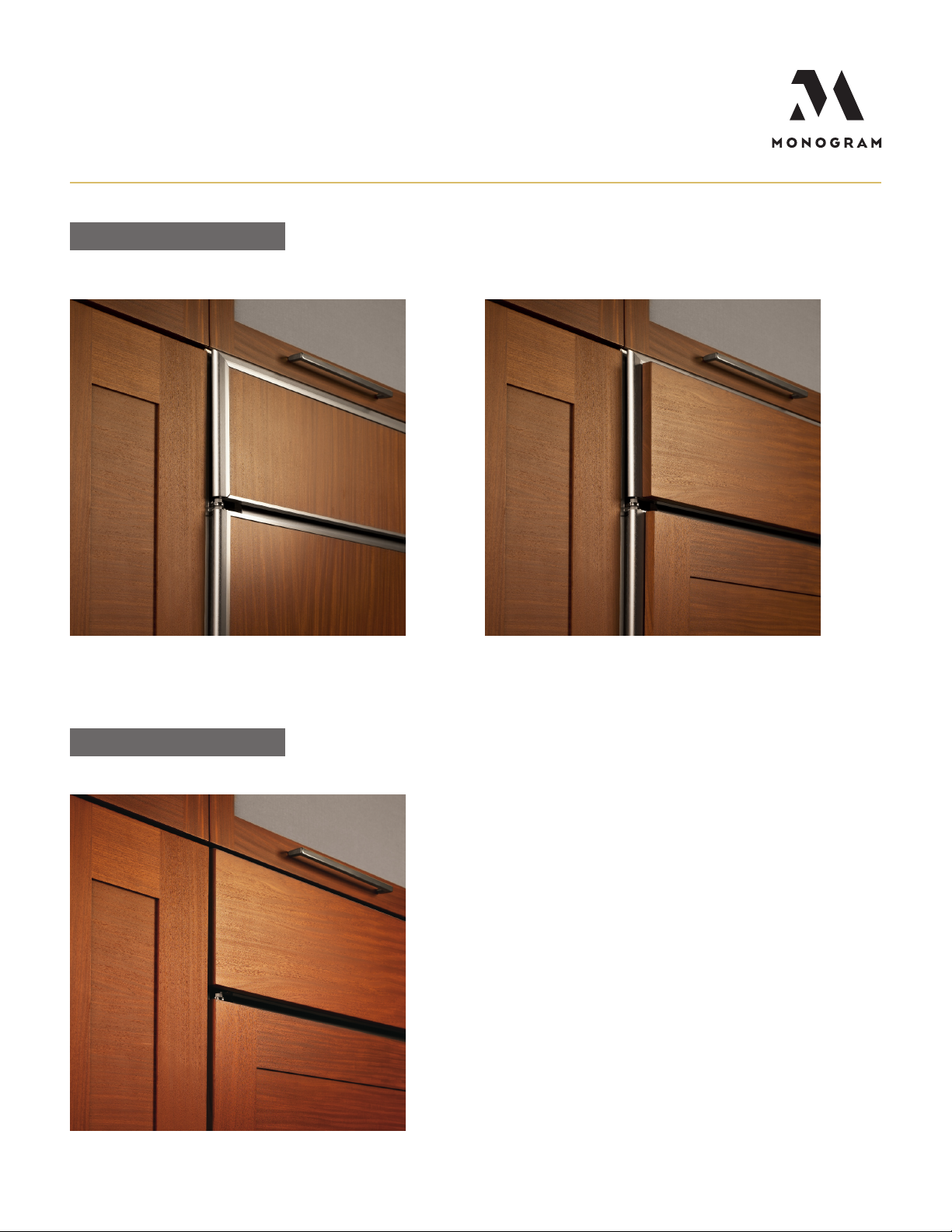
SECTION 1
STANDARD INSTALLATION
1/4" FRAMED PANELS 3/4" OVERLAY PANELS
SECTION 2
FLUSH INSET INSTALLATION
For questions about your
appliance, please call 1-800-626-2000.
PAGE 2 OF 14
Product Specication Created 10/19
Page 3
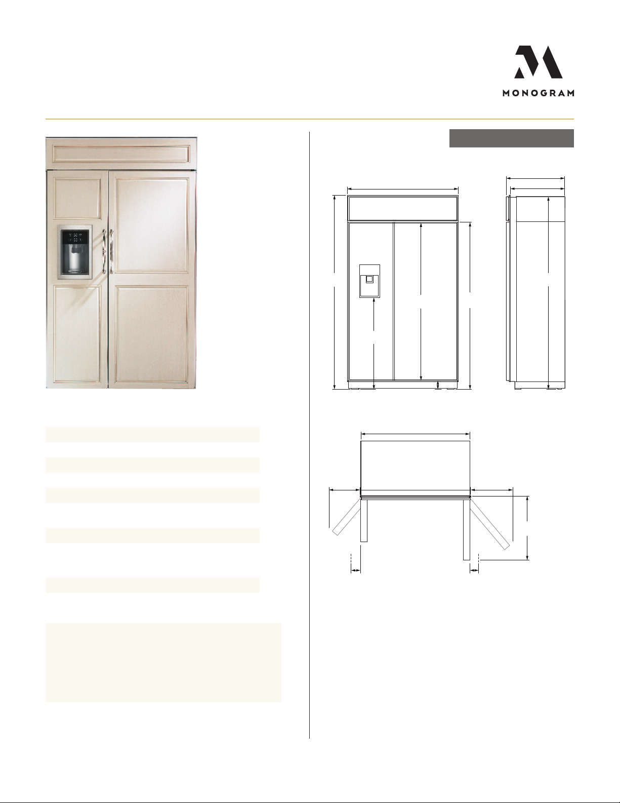
OVERALL DIMENSIONS
48" (121.9)
STANDARD INSTALLATION
25 1/2" (64.8)
23 1/2" (59.7)
SPECIFICATIONS
Overall Width 48" (121.92 cm)
Overall Height 84" (213.36 cm)
Overall Depth 25 3/8" (64.453 cm)
Door Clearance 28 5/8" (72.1 cm)
Cutout Width 47 1/2" (120.7 cm)
Cutout Height 83 1/2" - 84 1/2"
(212.1 - 214.6 cm)
Cutout Depth 24" (61 cm)
Plumbing Requirements 1/4" OD copper
tubing or GE
SmartConnect kit
Shipping Weight 775 lb
ATTENTION ELECTRICIAN:
A 115 volt 60Hz., 15 or 20 amp power supply is required. An
individual properly grounded branch circuit or circuit breaker
is recommended. Install a properly grounded 3-prong electrical
receptacle recessed into the back wall.
*84"
(213.4)
*40"
(101.6)
68 1/2"
(174.0)
*3 3/4"
(9.5)
*72 1/4"
(183.5)
*83 1/2"
(212.1)
SIDE VIEWFRONT VIEW
* Shipping height. Use leveling legs and wheels for maximum
1" height adjustment from shipping height.
47" (119.4)
Case width
**
Allow
15" (38.1)
min clearance
for 130˚ door swing
**
Allow
20" (50.8)
min clearance
for 90˚ door swing
28 5/8"
(72.7)
TOP VIEW
** Allow 4 9/16" (11.6) min
clearance to a wall for 90˚
door swing
** These refrigerators are equipped with a 3-position door stop. The factory-set 115° door
swing can be adjusted to 90° if clearances to adjacent cabinets or walls is restricted.
Allow full 130° door swings for pan removal. If the 90° door stop position is used, pan
access is maintained, but pan removal is restricted. Dimensions based on custom
handle height of 2 9/16" (6.5).
** Allow 4 9/16" (11.6) min
clearance to a wall for 90˚
door swing
For questions about your
appliance, please call 1-800-626-2000.
Dimensions in parentheses a re in centimeters unless otherwise noted.
Actual product dimensions may vary due to ma nufacturing tolerances.
Product Specication Created 10/19PAGE 3 OF 14
Page 4
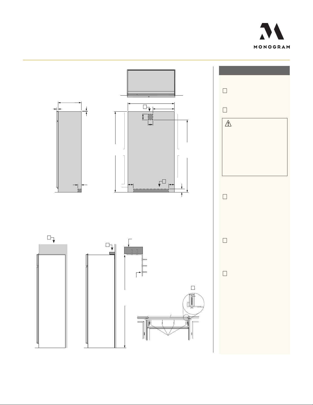
STANDARD INSTALLATION
FRONT VIEW SIDE VIEW
W
24" (61.0)
1 1/2"
(3.8)
3 1/4"
(8.3)
7/16"
(1.1)
Trim overlap
3 1/2"
(8.9)
E
WATER
47 1/2" (120.7)
20" (50.8)
*83 1/2" min
*84 1/2" max
(212.1-214.6)
*Trim will overlap
additional 7/16"
3 1/2"
(8.9)
75"
(190.5 )
From floor
to bottom
of electrical
area
6"
(15.2)
5"
(12.7)
5"
(12.7)
5"
(12.7)
AND NO SOFFIT
AND NO SOFFIT
STANDARD INSTALLATION
24" (61)
1 9/16"
(3.97)
SIDE VIEW
e refrigerator will project forwa rd, slightly beyond adjacent cabinetry.
7/16"
Trim overlap
3 1/2"
(8.9)
(1.1)
*Trim will overlap
*84 1/2"
(214.6)
additional 7/16"
5"
(12.7)
6"
(15.24)
ANTI-TIP BRACKET
C
SOFFIT
SIDE VIEW INSTALLED
UNDER SOFFIT
D
SIDE VIEW INSTALLED
WITH WOODEN WALL STUDS
Screws mounted
into vertical wall
*84"
(213.4)
*Or installation
height from floor
2" x 4"
Cut to 35" Length
studs
TOP VIEW
47 1/2" (120.7)
20" (50.8)
A
E
5"
(12.7)
5"
B
(12.7)
WATERW
FRONT VIEW
Top Case Trim
Install Screws
Through Trim and Into
3/4" Min. Wood Brace
FRONT VIEW INSTALLED
WITH METAL WALL STUDS
(190.5 )
From floor
to bottom
of electrical
3 1/2"
(8.9)
75"
area
E
3/4"
Min.
Side View Top
Case Trim
HELPFUL TIPS
A
Mounting the junction box in this
location will also allow for front
accessibility through access panel.
B
Water supply a rea.
WARNING:
e refrigerator is top heavy
and must be secured to prevent
the possibility of tipping forward.
Failure to do so may result in dea th
or serious injury.
e information below is for ca binet
design only. When installing the antitip system you must use the product
installation instructions.
Determine your installation construction
and required a nti-tip configuration:
C
Installed Under Soffit
After installing unit into installation
opening, raise grille pa nel and screw
metal case sides to adjacent cabinet.
When installed under a soffit, the
soffit cannot exceed 24" deep. e top
case trim overlaps the bottom
of the soffit.
D
Wooden Wall Studs and No Soffit
• Cut a 2" x 4" block and secure to
brackets provided.
• Secure brackets to back wall of
opening at 84" or your installa tion
height from the floor.
E
Metal Wall Studs and No Soffit
is method requires securely
fastened cabinets on both sides a nd
a 3/4" minimum wood brace a bove
unit, with it’s front surface 24" from
back wall.
• After installing unit into opening,
raise grille pa nel and attach metal
case top trim to 3/4" minimum
wood brace.
• e brace spanning the enclosure
must be securely fastened to
cabinets on both sides.
See Installation Instructions for
detailed instructions.
For questions about your
appliance, please call 1-800-626-2000.
PAGE 4 OF 14
Product Specication Created 10/19
Page 5
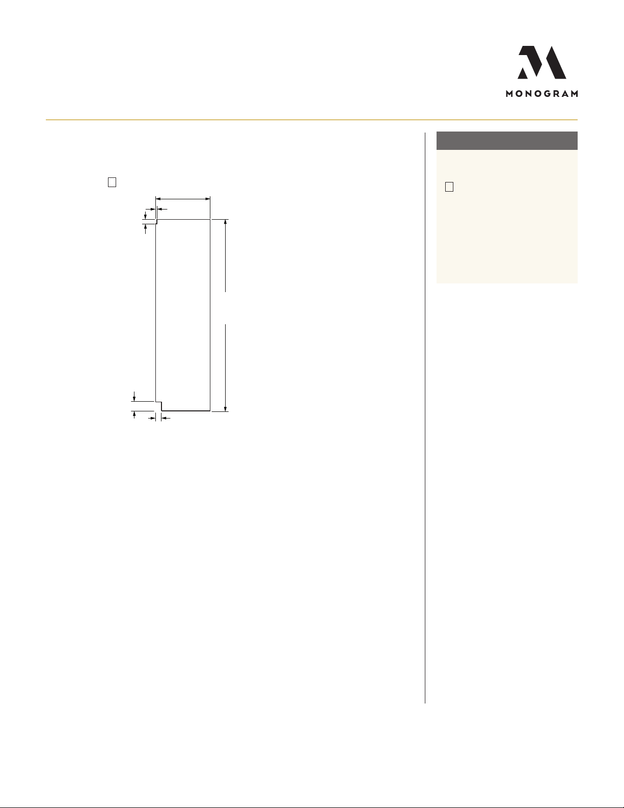
CUSTOM SIDE PANELS
F
1 7/8"
*3"- 4"
(7.6 - 10.2)
*Depending
on installation
height
(4.8)
24" (61.0)
3/16"
(.5)
2 9/16"
(6.5)
*84"
(213.4)
*Depending
on installation
height
STANDARD INSTALLATION
HELPFUL TIPS
F
Side panels must be used
whenever the sides of the
refrigerator will be exposed. e
1/4" side panels will slip into the
side case trim. Secure the panels
to the refrigerator with stick-on
hook and loop fastener strips.
Order the side panels from the
cabinet ma nufacturer.
For questions about your
appliance, please call 1-800-626-2000.
PAGE 5 OF 14
Product Specication Created 10/19
Page 6
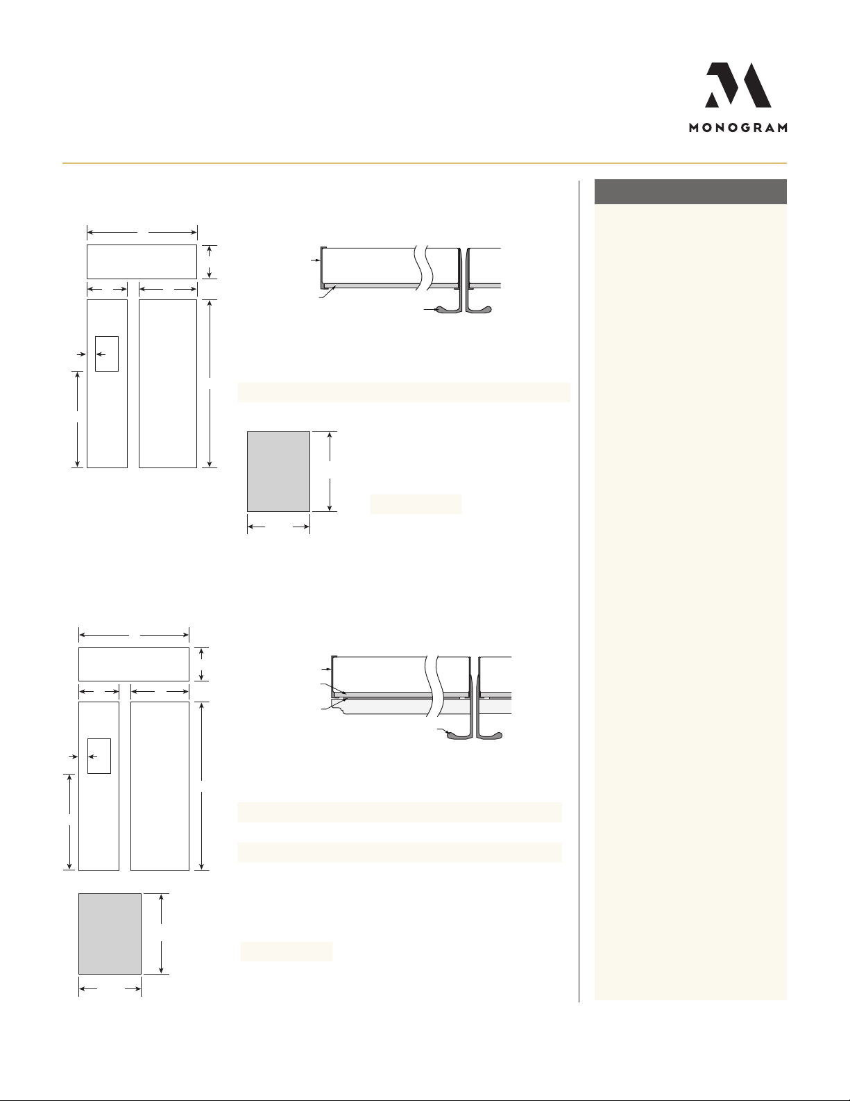
1/4" FRAMED PANEL DIMENSIONS
1/4" Framed Panel
A
G
G
STANDARD INSTALLATION
HELPFUL TIPS
Trimmed refrigerators a re designed to
be customized with decorative pa nels.
Field-installed custom door and grille
panels a re required.
1/4" FRAMED PANELS:
For 1/4" thick custom panels ordered
Grille Panel
D E
Dispenser
Cutout
PANEL ASSEMBLY CROSS SECTION
B
Trim
Optional ZKLN kit handles
Door
from your cabinet maker; the
decorative pa nels slide into the trim.
MAXIMUM TOTAL PANEL
WEIGHT:
• Fresh food door panel – 75 lbs.
• Freezer drawer panel – 53 lbs.
• Grille panel – 18 lbs
F
Freezer
Panel
Fresh
Food
Panel
PANEL DIMENSIONS
C
1/4" Framed Panel 45 7/8" 9 1/2" 68 3/8" 18 9/16" 26 9/16"
Dispenser
Cutout
13 5/16"
A B C D E
(33.8)
DISPENSER CUTOUT POSITION
F G
34 3/16" 3 7/8"
11"
(27.9)
3/4" OVERLAY PANEL DIMENSIONS
3/4" OVERLAY PANELS:
For 3/4" thick custom panels ordered
from your cabinet maker; the
decorative pa nels slide into the trim.
e overlay panel must be secured
to a 1/4"-thick backer pa nel which
slides into the trim.
A spacer panel 0.10" thick must be
placed between the overlay and
backer panels.
Grille Panel
D E
Dispenser
Cutout
A
PANEL ASSEMBLY CROSS SECTION
B
1/4" Backer Panel
.10" Spacer Panel
Trim
3/4" Overlay Panel
Optional ZKLN kit handles
Door
Center each panel over the other.
Assemble the panels with glue a nd
screws. Screws must be countersunk
into the backer panel.
NOTE: Left-to-right offset is not
always equal to top-to-bottom offset.
MAXIMUM TOTAL PANEL
WEIGHT:
• Fresh food door panel – 75 lbs.
F
Freezer
Panel
Fresh
Food
Panel
PANEL DIMENSIONS
C
A B C D E
1/4" Backer Panel 45 7/8" 9 1/2" 68 3/8" 18 9/16" 26 9/16"
.10" Spacer Panel 45" 8 5/8" 67" 17 1/4" 25 1/4"
3/4" Overlay Panel 46 1/8" 9 3/4" 68 5/8" 18 13/16" 26 13/16"
.25" + .10" + .75" = 1.10" Total Panel Thickness
• Freezer drawer panel – 53 lbs.
• Grille panel – 18 lbs
Door handles not included. Custom
handles supplied by your ca binet
maker may be used. Optional visor
handle kit ZKLN is ava ilable.
Dispenser
Cutout
13 5/16"
(33.8)
* DISPENSER CUTOUT POSITION
F G
34 5/16" 4"
* Cut the dispenser opening after the backer, spacer
and overlay panels have been assembled.
Kit includes two handles.
11"
(27.9)
For questions about your
appliance, please call 1-800-626-2000.
PAGE 6 OF 14
Product Specication Created 10/19
Page 7
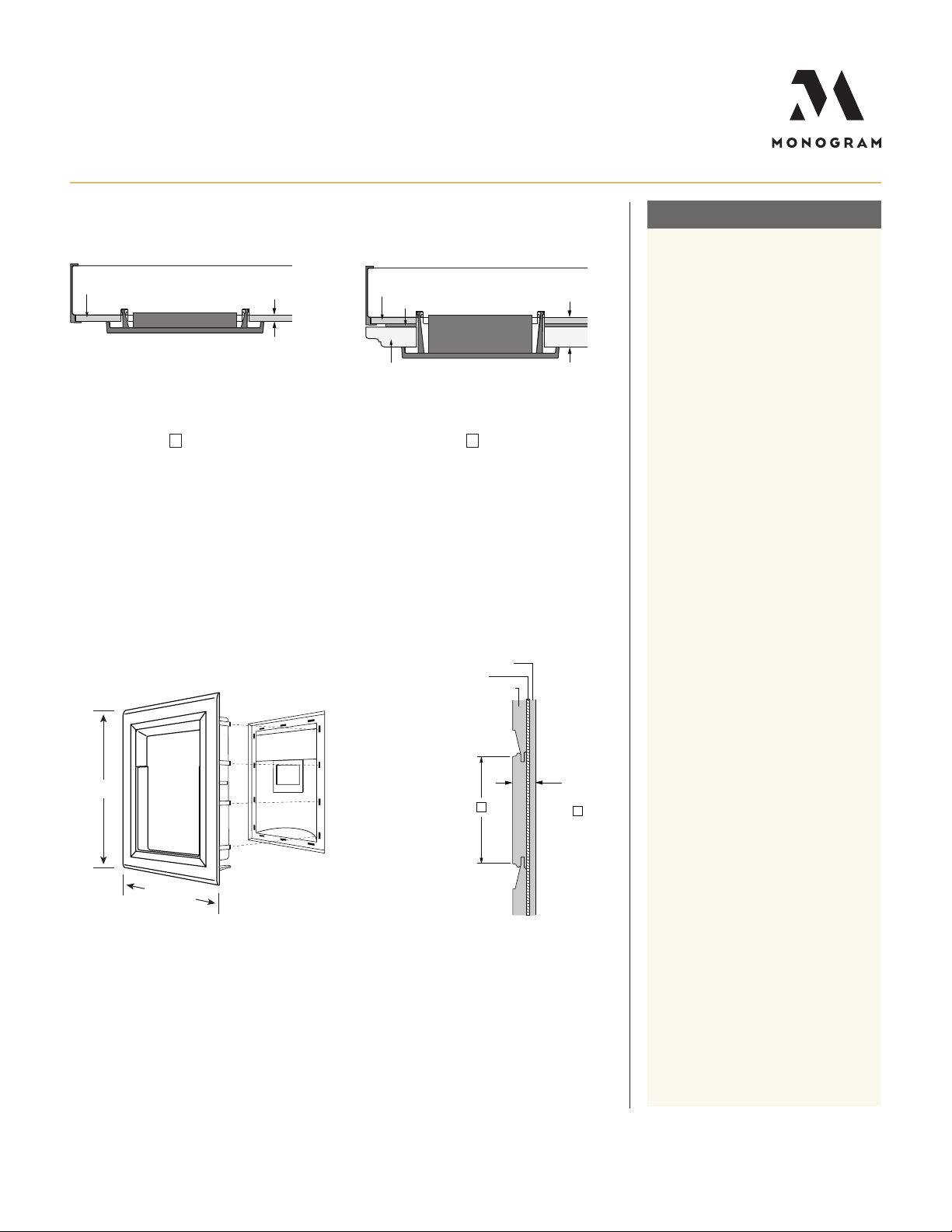
DISPENSER TRIM
STANDARD INSTALLATION
HELPFUL TIPS
1/4" Framed Panel
Freezer Door
Ice/Water Dispenser
1/4"
Total
Thickness
1/4" Backer Panel
3/4" Overlay Panel
Freezer Door
.10" Spacer Panel
Ice/Water Dispenser
1.10"
Total
Thickness
1/4" PANEL DISPENSER TRIM 3/4" OVERLAY PANEL DISPENSER TRIM
A B
RAISED OVERLAY PANEL DESIGN ON DISPENSER MODELS
1/4" Backer Panel
.10" Spacer
3/4" Overlay Panel
14"
C
1.10"
Thickness
11 3/4"
Total
D
ese refrigerators a re supplied with two
dispenser trims, one for framed pa nels
and one for overlay pa nels.
1/4" PANEL DISPENSER TRIM:
e framed pa nel must be 1/4" nominal
thickness to fit the dispenser trim.
• e dispenser trim fits over the custom
panel a nd snaps into the freezer door.
• If the panel is less tha n 0.250" thick, a
noticeable gap may be crea ted around
the dispenser trim. Foam tape may be
applied on the door to improve the fit.
• If the panel is more tha n 0.250" thick,
the dispenser trim cannot be secured to
the door.
3/4" OVERLAY PANEL
DISPENSER TRIM:
e 3/4" overlay dispenser trim is designed
to fit a total pa nel thickness of 1.100".
• If the panel is less than 1.100" thick, a
noticeable gap may be crea ted around
the dispenser trim.
• If the panel is more tha n 1.100" thick,
the dispenser trim cannot be secured to
the door.
• e overlay panel must be constructed
according to the specifications shown to
achieve the correct total thickness.
• Alternative pa nel construction methods
such as securing a 3/4" pa nel to a 1/4"
backer panel ca nnot be used. Another
method, routing a 3/4"-thick pa nel on
all sides, cannot be used. ese methods
will not result in the required
1.100" panel thickness.
• When a ra ised panel design is to be used,
a custom middle ra il is required.
DISPENSER TRIM SIDE VIEW CROSS SECTION
For questions about your
appliance, please call 1-800-626-2000.
(SHOWING RAISED OVERLAY
WITH MIDDLE RAIL)
PAGE 7 OF 14
RAISED OVERLAY PANEL
DESIGN ON DISPENSER
MODELS:
When a ra ised panel design is to be used,
a custom wide middle ra il is required to
accept the dispenser trim.
• e middle rail must be wide enough to
allow for the dispenser trim to overlap
the opening.
• e middle rail must be 1.10" total
thickness to accept the dispenser trim.
Product Specication Created 10/19
Page 8
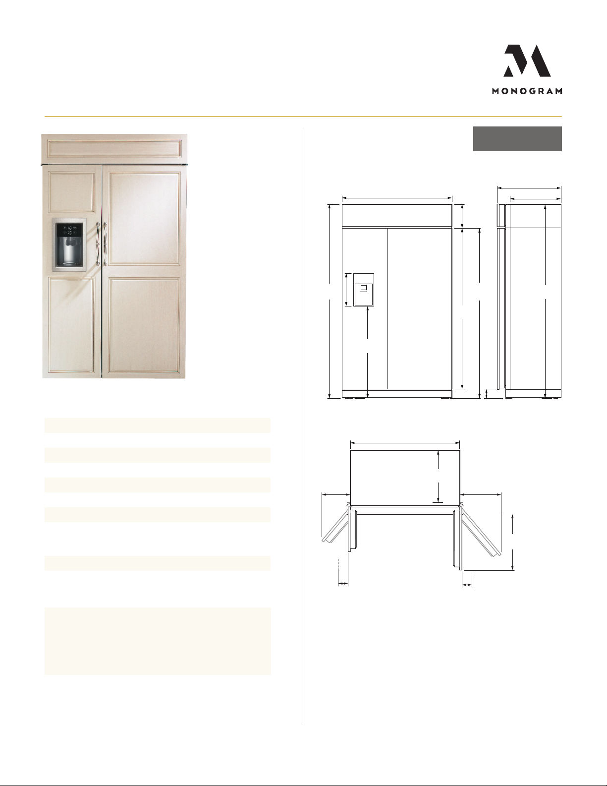
OVERALL DIMENSIONS
AFTER PANEL INSTALL
FLUSH INSET
INSTALLATION
SPECIFICATIONS
Overall Width 50" (127.0 cm)†
Overall Height 84 1/2" (214.6 cm) †
Overall Depth 26" (66.0 cm) †
Door Clearance 28 5/8" (72.1 cm)
Cutout Width 51" (129.5 cm)
Cutout Height 85" (215.9 cm)
Cutout Depth 26 3/16" (66.5 cm)
Plumbing Requirements 1/4" OD copper
tubing or GE
SmartConnect kit
Shipping Weight 775 lb (351.5 kg)
† Dimensions include 3/4" custom cabinet panel
ATTENTION ELECTRICIAN:
A 115 volt 60Hz., 15 or 20 amp power supply is required. An
individual properly grounded branch circuit or circuit breaker
is recommended. Install a properly grounded 3-prong
electrical receptacle recessed into the back wall.
50" (127.0)
11 11/16"
15 3/8"
(39.1)
68 5/8"
(174.3)
72 5/8"
84 1/2"
(214.6)
*39 17/32"
(100.4)
FRONT VIEW
Use leveling legs and wheels for maximum 1" height
adjustment from shipping height. Nominal installation height is 84”
47" (119.4)
Case width
**
Allow
13" (33.0)
min clearance
for door swing
*115° Door swing
Doors can be adjusted to
90° door swing
20 5/8"
(52.4)
Allow
min clearance
for door swing
(29.7)
(184.5)
(10.2)
**
20" (50.8)
4"
20 5/8" (52.4)
SIDE VIEW
28 5/8"
(72.7)
TOP VIEW
26" (66.0)
** Allow 4 9/16" (11.6) min
clearance to a wall for 90˚
door swing
** These refrigerators are equipped with a 3-position door stop. The factory-set 115° door
swing can be adjusted to 90° if clearances to adjacent cabinets or walls is restricted.
Allow a 15" minimum clearance to wall for pan removal. If the 90° door stop position is
used, pan access is maintained, but pan removal is restricted. A 130° door swing option
is available for standard installation only. Dimensions based on custom handle height
of 2-9/16” (6.5).
** Allow 4 9/16" (11.6) min
clearance to a wall for 90˚
door swing
* 83 1/2"
(212.1)
For questions about your
appliance, please call 1-800-626-2000.
Dimensions in parentheses a re in centimeters unless otherwise noted.
Actual product dimensions may vary due to ma nufacturing tolerances.
Product Specication Created 10/19PAGE 8 OF 14
Page 9
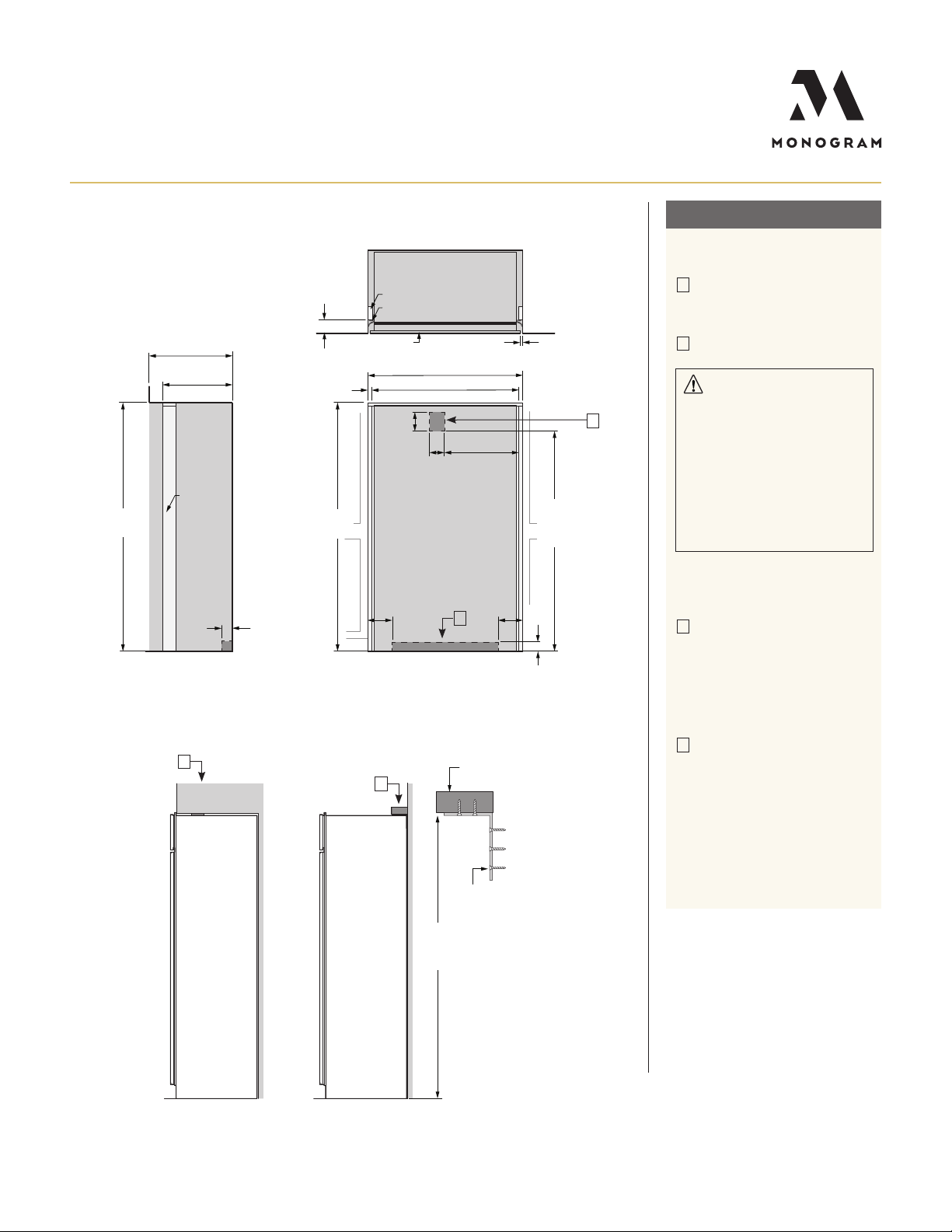
FLUSH INSET INSTALLATION 3/4" PANELS
FRONT VIEW SIDE VIEW
W
24" (61.0)
1 1/2"
(3.8)
3 1/4"
(8.3)
7/16"
(1.1)
Trim overlap
3 1/2"
(8.9)
E
WATER
47 1/2" (120.7)
20" (50.8)
*83 1/2" min
*84 1/2" max
(212.1-214.6)
*Trim will overlap
additional 7/16"
3 1/2"
(8.9)
75"
(190.5 )
From floor
to bottom
of electrical
area
6"
(15.2)
5"
(12.7)
5"
(12.7)
5"
(12.7)
AND NO SOFFIT
FLUSH INSET INSTALLATION
FLUSH INSET KIT ZKFN REQUIRED
26 3/16" (66.5)
Flush inset depth
20 15/16" (53.2)
Depth to cleat
85"
(215.9)
ANTI-TIP BRACKET
Finished
cleats
C
SOFFIT
W
3 1/2"
(8.9)
5 1/4" (13.3)
3/4" (1.9)
Width of side cleats
85"
(215.9)
TOP VIEW
Finished cleats
Case Trim
3/4" Panel
51" (129.5) Flush inset width
49 1/2" (125.7)
Width between cleats
6"
E
(15.2)
7"
(17.8)
5"
(12.7)
WATER
FRONT VIEWSIDE VIEW
D
Case
Door
B
22 1/4"
(56.5)
7"
(17.8)
2" x 4"
Cut to 35" Length
1/2" (1.3)
From floor
to bottom
of electrical
3 1/2"
(8.9)
75"
(190.5 )
area
HELPFUL TIPS
A
Mounting the junction box in this
location will also allow for front
accessibility through access panel.
B
Water supply a rea.
WARNING:
A
e refrigerator is top heavy a nd
must be secured to prevent the
possibility of tipping forward. Fa ilure
to do so may result in death or
serious injury.
e information below is for ca binet
design only. When installing the antitip system you must use the product
installation instructions.
Determine your installation
construction and required a nti-tip
configuration:
C
Cut a 1" x 4" block 35" long.
Measure and ma rk under the soffit,
5 1/4" from the front edge of the
cabinet. Secure the wood block
under the soffit. From the bottom
of the block to the finished floor
should measure 84".
D
Wooden Wall Studs and No Soffit
• Cut a 2" x 4" block and secure to
brackets provided.
• Secure brackets to back wall
of opening at 84" or your
installation height from the floor.
SIDE VIEW INSTALLED
UNDER SOFFIT
For questions about your
appliance, please call 1-800-626-2000.
Screws mounted
into vertical wall
*84"
(213.4)
*Or installation
height from floor
SIDE VIEW INSTALLED
WITH WOODEN WALL STUDS
PAGE 9 OF 14
See Installation Instructions for
detailed instructions.
studs
Product Specication Created 10/19
Page 10
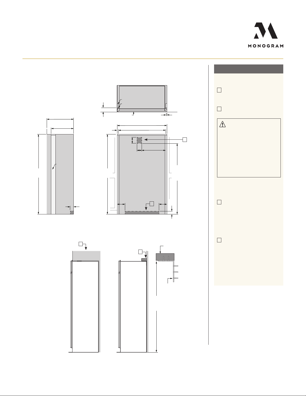
FLUSH INSET INSTALLATION 1/2" PANELS
FRONT VIEW SIDE VIEW
W
24" (61.0)
1 1/2"
(3.8)
3 1/4"
(8.3)
7/16"
(1.1)
Trim overlap
3 1/2"
(8.9)
E
WATER
47 1/2" (120.7)
20" (50.8)
*83 1/2" min
*84 1/2" max
(212.1-214.6)
*Trim will overlap
additional 7/16"
3 1/2"
(8.9)
75"
(190.5 )
From floor
to bottom
of electrical
area
6"
(15.2)
5"
(12.7)
5"
(12.7)
5"
(12.7)
AND NO SOFFIT
FLUSH INSET INSTALLATION
FLUSH INSET KIT ZKFN REQUIRED
26 3/16" (66.5)
Flush inset depth
20 13/16" (52.9)
Depth to cleat
85"
(215.9)
ANTI-TIP BRACKET
Finished
cleats
W
3 1/2"
(8.9)
C
SOFFIT
5 3/8" (13.7)
3/4" (1.9)
Width of side cleats
85"
(215.9)
TOP VIEW
Finished cleats
Case Trim
1/2" Panel
51" (129.5) Flush inset width
49 1/2" (125.7)
Width between cleats
6"
(15.2)
E
5"
(12.7)
7"
(17.8)
WATER
FRONT VIEWSIDE VIEW
Case
Door
D
22 1/4"
(56.5)
B
7"
(17.8)
3 1/2"
2" x 4"
Cut to 35" Length
1/2" (1.3)
75"
(190.5 )
From floor
to bottom
of electrical
area
(8.9)
HELPFUL TIPS
A
Mounting the junction box in this
location will also allow for front
accessibility through access panel.
B
Water supply a rea.
WARNING:
e refrigerator is top heavy a nd
A
must be secured to prevent the
possibility of tipping forward.
Failure to do so may result in dea th
or serious injury.
e information below is for ca binet
design only. When installing the antitip system you must use the product
installation instructions.
Determine your installation
construction and required a nti-tip
configuration:
C
Cut a 1" x 4" block 35" long.
Measure and ma rk under the
soffit, 5 3/8" from the front edge of
the cabinet. Secure the wood block
under the soffit. From the bottom
of the block to the finished floor
should measure 84".
D
Wooden Wall Studs and No Soffit
• Cut a 2" x 4" block and secure to
brackets provided.
• Secure brackets to back wall
of opening at 84" or your
installation height from the floor.
SIDE VIEW INSTALLED
UNDER SOFFIT
For questions about your
appliance, please call 1-800-626-2000.
Screws mounted
into vertical wall
*84"
(213.4)
*Or installation
height from floor
SIDE VIEW INSTALLED
WITH WOODEN WALL STUDS
See Installation Instructions for
detailed instructions.
studs
Product Specication Created 10/19PAGE 10 OF 14
Page 11
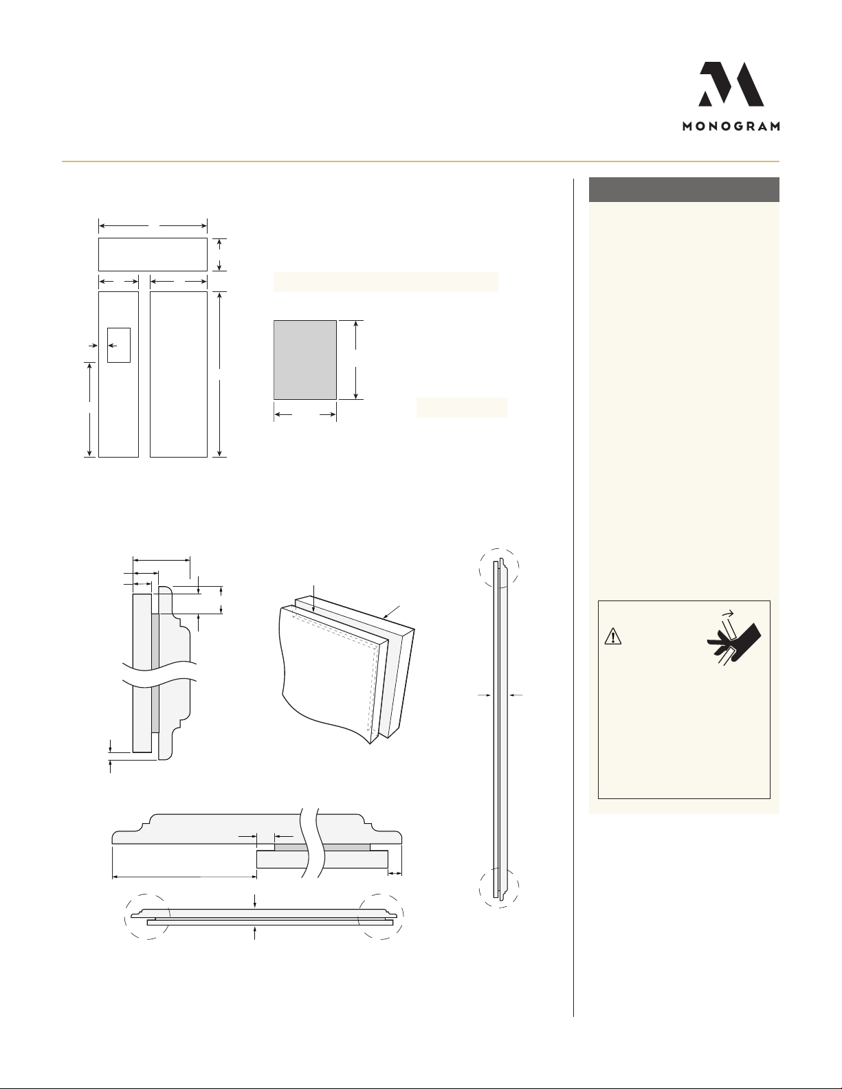
FLUSH INSET 3/4" PANEL DIMENSIONS
Front
A
G
PANEL DIMENSIONS
B
C
F
Dispenser
Cutout
Freezer
Panel
Grille Panel
D E
Fresh
Food
Panel
3/4" RAISED DOOR PANEL ROUTING
DETAIL TOP
3/4"
11/32"
1/4"
7/16"
1/4"
A B C D E
50" 11 3/16" 68 5/8" 20 7/8" 28 7/8"
Dispenser
Cutout
13 5/16"
(33.8)
DISPENSER CUTOUT
POSITION
F G
11"
(27.9)
NOTE: Routed areas should
be finished as they may be
visible when assembled.
34 9/32" 5 15/16"
Front
TOP
FLUSH INSET INSTALLATION
HELPFUL TIPS
Trimmed refrigerators a re designed
to be customized with decorative
panels. Field-installed 1/2" or 3/4"
custom door and grille pa nels are
required. For 3/4" raised door a nd
grille panels, routing is required.
e router depth is 1/4" all the way
around the pa nel’s backs. Additional
panel width reductions a re required
per the diagrams shown. is will
create “picture fra me” routing
allowing the panels to slide into the
attached door a nd grille trims.
MAXIMUM TOTAL PANEL
WEIGHT:
• Fresh food door panels – 75 lbs.
• Freezer drawer panel – 53 lbs.
• Grille panel – 18 lbs.
DOOR HANDLES
Door handle not included. A custom
handle supplied by your ca binet
maker may be used.
WARNING:
Door Trim Pinch Point
Back
FrontBack
Haza rd Improper installation can
lead to a finger pinch point ha zard
between the side door trim and
the cabinets when opera ting the
3/16"
CORNER VIEW SHOWING
DETAIL BOTTOM
DETAIL HINGE
SIDE
ROUTER DEPTH 1/4"
2 1/16"
HINGE
SIDE
3/4" PANEL BOTTOM VIEW
(AFTER ROUTING)
“PICTURE FRAME” ROUTING
Back
DETAIL HANDLE
3/16"
SIDE
HANDLE
SIDE
BOTTOM
3/4" PANEL SIDE VIEW
(AFTER ROUTING)
door, especially with children. To
minimize this risk you must follow
the installation instructions for
cabinet dimensions, trim assembly
and door stop a ngle.
For questions about your
appliance, please call 1-800-626-2000.
Product Specication Created 10/19PAGE 11 OF 14
Page 12
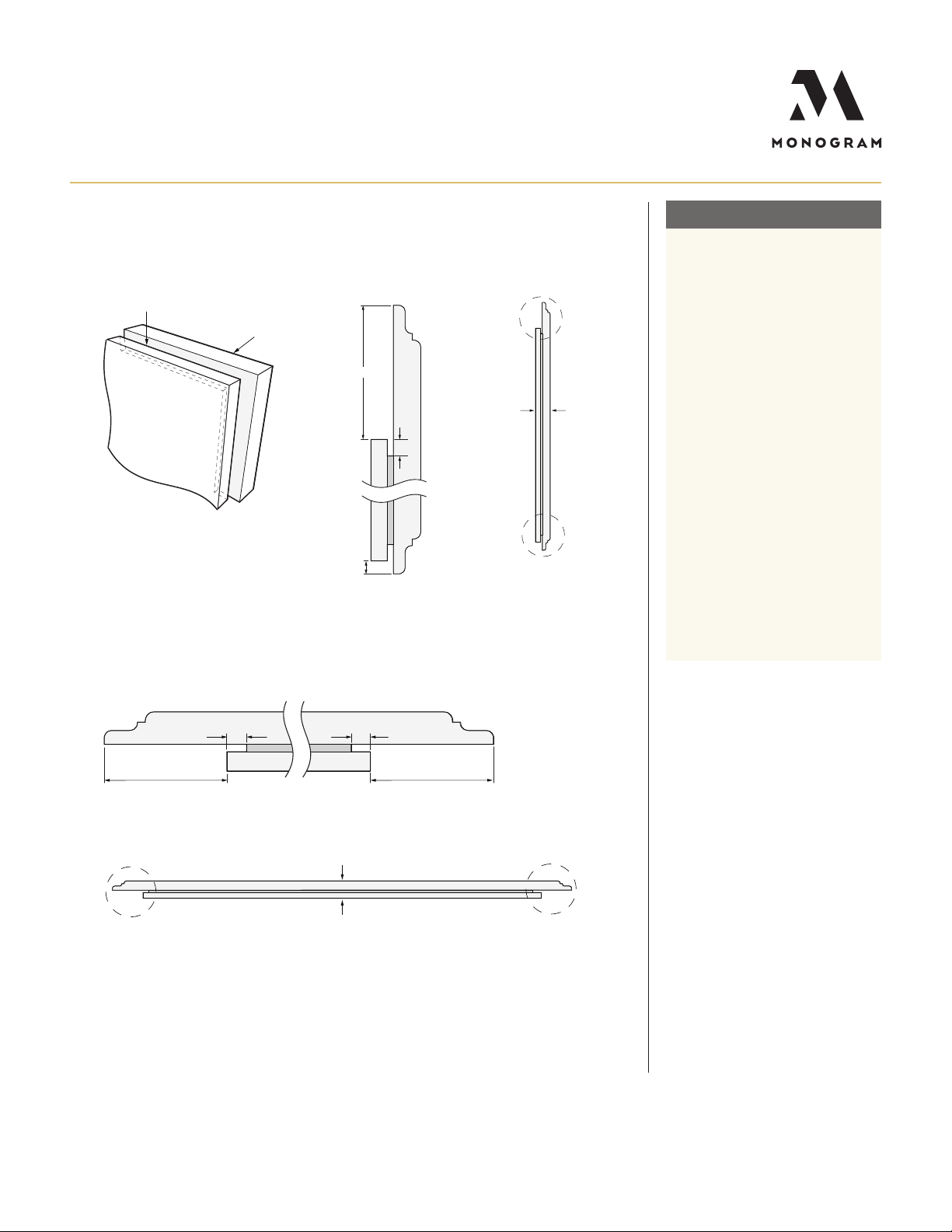
NOTE: Routed areas should
be finished as they may be
visible when assembled.
Back
CORNER VIEW SHOWING
“PICTURE FRAME” ROUTING
Front
DETAIL TOP
2"
3/16"
DETAIL BOTTOM
ROUTER DEPTH 1/4"
TOP
FrontBack
BOTTOM
3/4" PANEL SIDE VIEW
(AFTER ROUTING)
STANDARD INSTALLATION
FLUSH INSET INSTALLATION3/4" RAISED GRILLE PANEL ROUTING
HELPFUL TIPS
HELPFUL TIPS
Trimmed refrigerators a re designed
to be customized with decorative
panels. Field-installed 1/2" or 3/4"
custom door and grille pa nels are
required. For 3/4" raised door a nd
grille panels, routing is required.
e router depth is 1/4" all the way
around the pa nel’s backs. Additional
panel width reductions a re required
per the diagrams shown. is will
create “picture fra me” routing
allowing the panels to slide into the
attached door a nd grille trims.
MAXIMUM TOTAL PANEL
WEIGHT:
• Fresh food door panels – 75 lbs.
• Freezer drawer panel – 53 lbs.
• Grille panel – 18 lbs.
DOOR HANDLES
Door handle not included. A custom
handle supplied by your ca binet
maker may be used.
LEFT
SIDE
LEFT SIDE
DETAIL
ROUTER DEPTH 1/4"
2 1/16" 2 1/16"
Front
Back
3/4" PANEL BOTTOM VIEW
(AFTER ROUTING)
DETAIL RIGHT
SIDE
ROUTER DEPTH 1/4"
RIGHT
SIDE
For questions about your
appliance, please call 1-800-626-2000.
PAGE 12 OF 14
Product Specication Created 10/19
Page 13
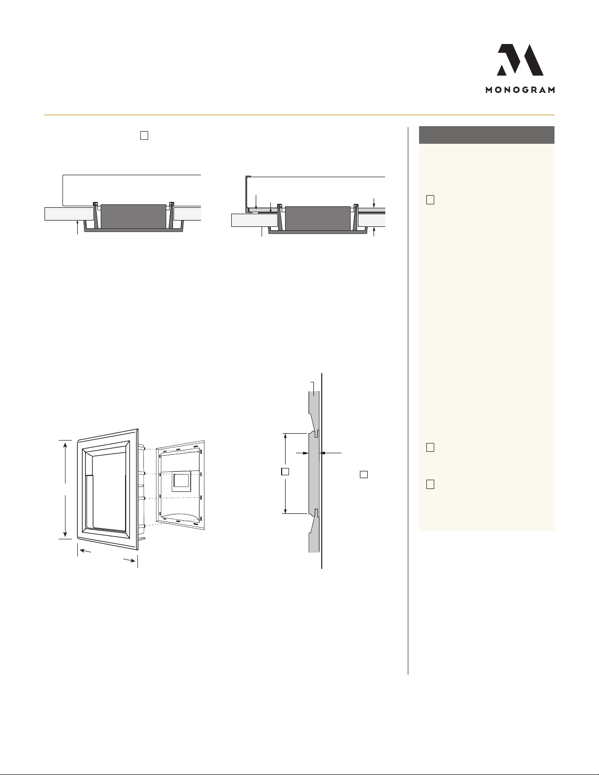
DISPENSER TRIM
Ice/Water Dispenser
3/4" Flush Panel
A
Freezer Door
1/2" Overlay Panel
3/4" OVERLAY PANEL DISPENSER TRIM
RAISED PANEL DESIGN ON DISPENSER MODELS
3/4" or 1/2" Flush Panel
1/4" Backer Panel
.10" Spacer Panel
Freezer Door
Ice/Water Dispenser
1/2" OVERLAY PANEL DISPENSER TRIM
.85"
Total
Thickness
FLUSH INSET INSTALLATION
HELPFUL TIPS
ese refrigerators a re supplied with
a dispenser trim for flush inset pa nels.
PANEL DISPENSER TRIM:
A
e provided dispenser trim
is designed to fit a total pa nel
thickness of 3/4" or 0.85".
• If the panel is less than 3/4"
thick, a noticea ble gap may
be created a round the
dispenser trim.
• If the panel is more tha n 0.85"
thick, the dispenser trim cannot
be secured to the door.
• e overlay panel must be
constructed according to the
specifications shown to achieve
the correct total thickness.
• When a ra ised panel design is
to be used, a custom middle
rail is required.
RAISED PANEL DESIGN ON
DISPENSER MODELS:
When a ra ised panel design is to be
used, a custom wide middle ra il is
required to accept the dispenser trim.
14"
11 3/4"
DISPENSER TRIM
3/4" or .85"
B
Thickness
SIDE VIEW CROSS SECTION
(SHOWING RAISED PANEL
WITH MIDDLE RAIL)
Total
C
e middle rail must be wide
B
enough to allow for the dispenser
trim to overlap the opening.
e middle rail must be 3/4" total
C
thickness for 3/4" panels or 0.85"
total thickness for 1/2" panels to
accept the dispenser trim.
For questions about your
appliance, please call 1-800-626-2000.
Product Specication Created 10/19PAGE 13 OF 14
Page 14
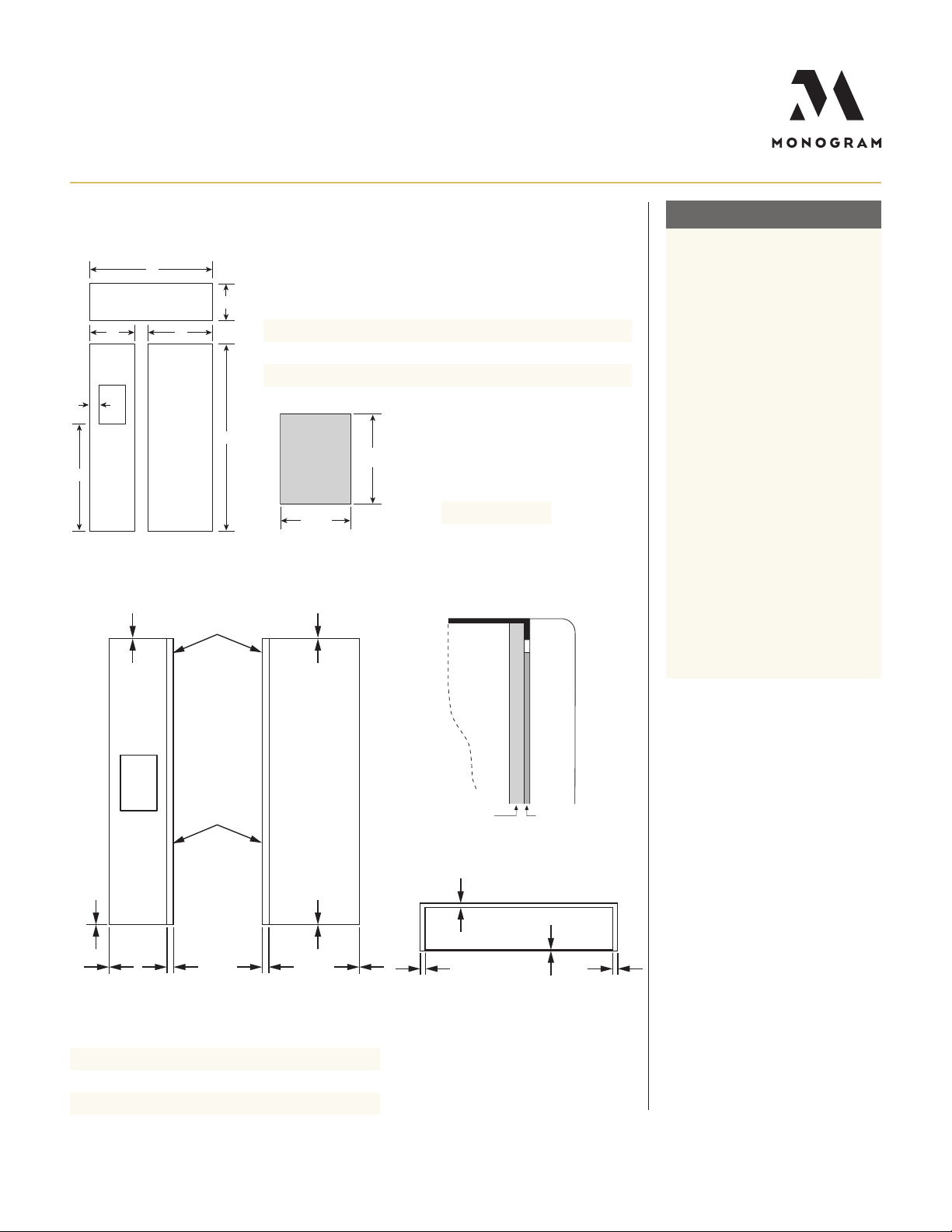
FLUSH INSET 1/2" PANEL DIMENSIONS
A
G
FLUSH INSET INSTALLATION
HELPFUL TIPS
PANEL DIMENSIONS
Grille Panel
D E
B
1/4" Backer Panel 45 7/8" 9 1/2" 68 3/8" 18 9/16" 29 9/16"
.10" Space Panel 45" 8 5/8" 67" 17 9/16" 25 9/16"
F
Dispenser
Cutout
Freezer
Panel
Fresh
Food
Panel
C
1/2" Overlay Panel 50" 11 3/16" 68 5/8" 20 7/8" 28 7/8"
Dispenser
Cutout
11"
(27.9)
13 5/16"
(33.8)
1/4" BACKER ASSEMBLY ROUTING DIMENSIONS
Hinge Side
C
C
A B C D E
DISPENSER CUTOUT
POSITION
F G
34 15/16" 5 5/16"
Door
1/2"
Overlay
Panel
e 1/2" overlay panel must be
secured to a .10" spacer pa nel and a
1/4" thick backer panel, which slides
into the trim.
ASSEMBLE THE PANELS
WITH GLUE AND SCREWS:
• Center the spacer panel on the
backer panel, left to right a nd
top to bottom. Secure the panels
with glue.
• Refer to the chart for loca ting the
backer panel to the overlay pa nel.
Secure the overlay panel to the
backer panel with glue a nd screws.
Screws must be countersunk into
the backer panel.
MAXIMUM TOTAL PANEL
WEIGHT:
• Fresh food door panel – 75 lbs.
• Freezer drawer panel – 53 lbs.
• Grille panel – 18 lbs.
Backer with
Overlay Panel
Assembly
Freezer
Back
D
A
AB
Fresh Food
Back
D
B
1/4"
Backer
Panel
Grille Back
C
A B
.10"
Spacer
D
PANEL DIMENSIONS
A B C D
Fresh Food Panel 2 1/16" 1/4" 1/8" 1/8"
Freezer Panel 2 1/16" 1/4" 1/8" 1/8"
Grille Panel 2 1/16" 2 1/16" 1 15/32" 7/32"
For questions about your
appliance, please call 1-800-626-2000.
Product Specication Created 10/19PAGE 14 OF 14
 Loading...