

Page 1
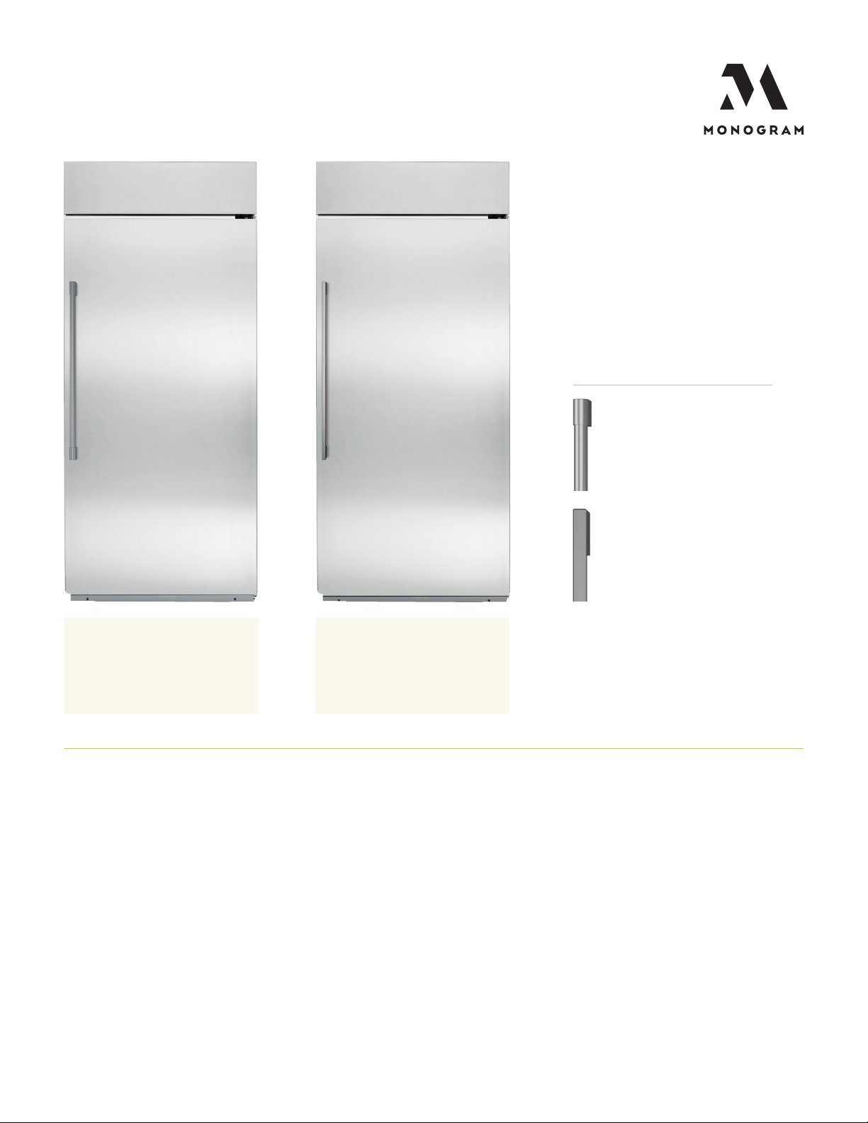
MONOGRAM 36" BUILT-IN
ALL-FREEZER
ZIFS360NNRH
When ordering this product,
be sure to use the model number
associated with the chosen handle.
Statemenet handle
ZKSP1H1PNSS
STATEMENT HANDLE
Model is shown with the Statement
handle, which needs to be ordered
separately. To order this handle
use model number ZKSP1H1PNSS.
MINIMALIST HANDLE
Model is shown with the Minimalist
handle, which needs to be ordered
separately. To order this handle
use model number ZKSP1H1CNSS.
ENHANCED TEMPERATURE MANAGEMENT SYSTEM
With precise electronic controls and thermistors, ma intains ideal
storage conditions for frozen foods
CONCEALED ICE DRAWER
Provides quick and easy access to filtered ice
GE WATER FILTRATION SYSTEM
Provides clean, fresh-tasting wa ter to the freezer's icemaker
Minimalist handle
ZKSP1H1CNSS
ADJUSTABLE, WIRE SHELVES, GALLON-SIZE
DOOR BINS AND PULLOUT BASKETS
Allow customizable storage for foods a nd containers of
varying sizes
CONCEALED HALOGEN LIGHTING SYSTEM
Illuminates contents without compromising space
For questions about your
appliance, please call 1-800-626-2000.
PAGE 1 OF 5
Product Specication Created 10/19
Page 2
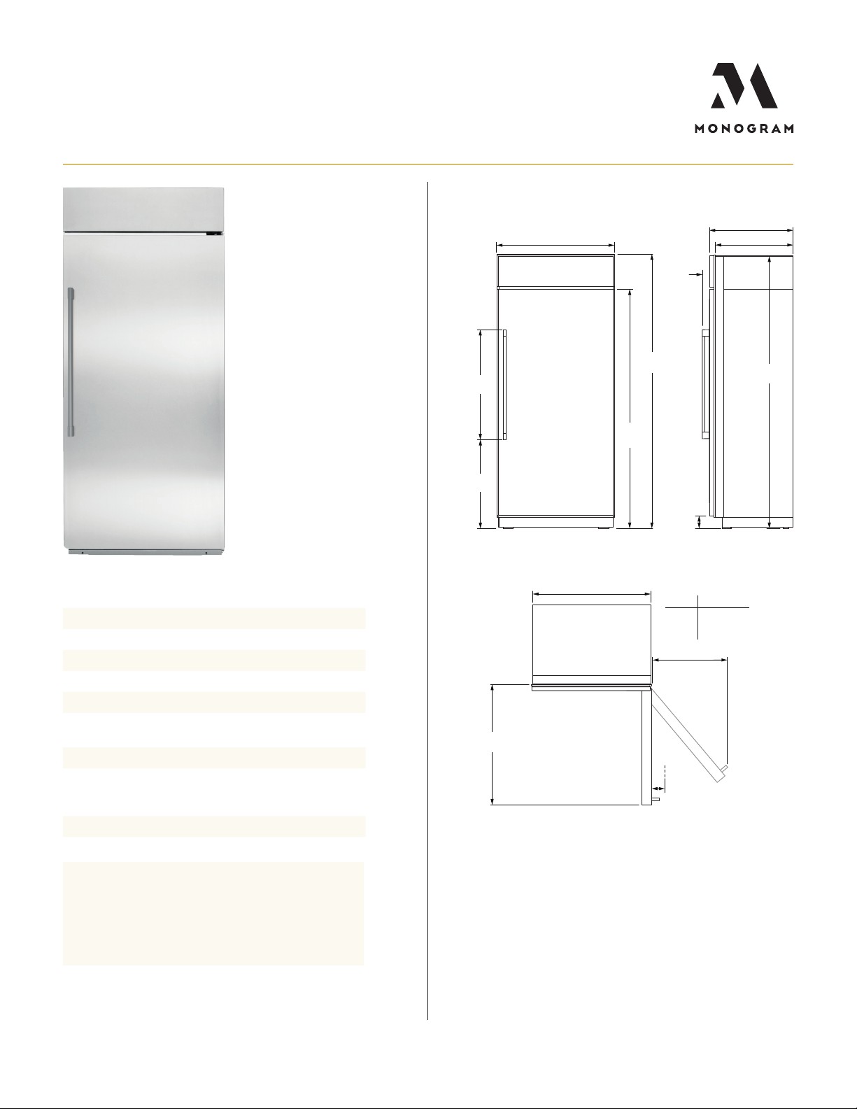
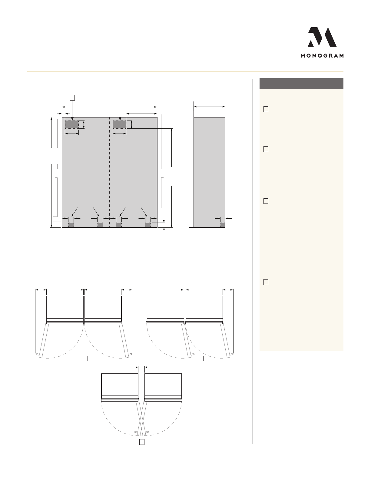
OVERALL DIMENSIONS
** These refrigerators are equipped with a 3 position door stop. The factory
set 115
or walls is restricted. Allow full 130
stop position is used, pan access is maintained, but pan removal is restricted.
* Shipping height . Use leveling legs and wheels for maximum
1" height adjustment from shipping height.
36" (91.4)
34 7/16"
(87.5)
*29 9/16"
(75.1)
*73 7/16"
(186.5)
*84"
(213.4)
2 1/8"
(5.4)
*3 15/16"
(10.0)
25 15/16" (65.9)
23 5/8" (60.0)
*83 1/2"
(212.1)
SIDE VIEWFRONT VIEW
SPECIFICATIONS
Overall Width 36" (91.4 cm)
Overall Height 84" (213.4 cm)
Overall Depth 25 15/16" (65.9 cm)
Door Clearance 36 1/2" (92.7 cm)
Cutout Width 35 1/2" (90.2 cm)
Cutout Height 83 1/2" - 84 1/2" (212.1 -
Cutout Depth 24" (61 cm)
Plumbing Requirements 1/4" OD copper
Shipping Weight 569 lb (258 kg)
ATTENTION ELECTRICIAN:
A 115 volt 60Hz., 15 or 20 amp power supply is required.
An individual properly grounded branch circuit or circuit
breaker is recommended. Install a properly grounded
3-prong electrical receptacle recessed into the back wall.
214.6 cm)
tubing or GE
SmartConnect kit
35" (88.9)
Case width
36 1/2"
(92.7)
˚ door swing can be adjusted to 90˚ if clearances to adjacent cabinets
TOP VIEW
˚ door swings for pan removal. If the 90˚ door
Door
Angle
** Dim A
90°
2 3/8"
115°
16" (40.6)
130°
22 3/4" (57.8)
**Dim A
** 4 1/8" (10.5) min
clearance to a wall
for 90˚ door swing
(6.0)
For questions about your
appliance, please call 1-800-626-2000.
Dimensions in parentheses a re in centimeters unless otherwise noted.
Actual product dimensions may vary due to ma nufacturing tolerances.
Product Specication Created 10/19PAGE 2 OF 5
Page 3
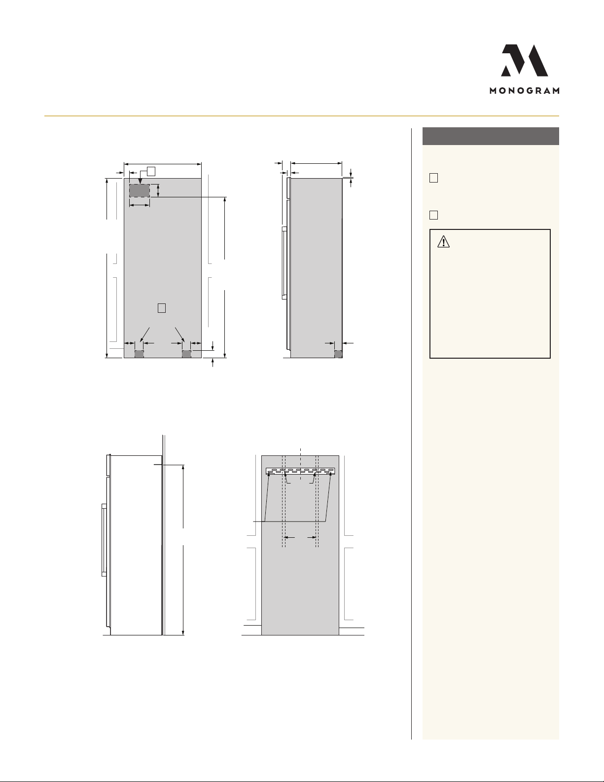
24" (61.0 )
4 1/2"
35 1/2"
SIDE VIEW
W
24" (61.0 )
2 3/8"
(6)
4 1/2"
(11.4)
7/16"
(1.1)
Trim overlap
3 1/2"
(8.9)
FRONT VIEW
ELEC.
35 1/2" (90.2)
3 1/2"
(8.9)
75
1/2
"
(191.8)
From floor
to bottom
of electrical
area
5 1/2"
(14.0)
9"
(22.9)
WITH ANTI-TIP BRACKET
5"
(12.7)
5"
(12.7)
WATER
3 1/2"
(9.0)
STANDARD INSTALLATION
STANDARD INSTALLATION
ANTI-TIP BRACKET
2 5/16"
(5.9)
*83 1/2" min
*84 1/2" max
(212.1-214.6)
*Trim will overlap
additional 7/16"
(12.7)
A
ELEC.
9"
(22.9)
5"
FRONT VIEW
5 1/2"
(14.0)
B
WATER
3 1/2"
(9.0)
(90.2)
81 1/2"
(207.0)
75
From floor
to bottom
of electrical
3 1/2"
5"
(8.9)
(12.7)
1/2
"
(191.8)
area
Use two
additional hole
locations at end
of brackets
(11.4)
2 3/8"
(6)
SIDE VIEW
C
L
Screws
mounted
into vertical
wall studs
Make sure
holes selected
are centered
on the studs
Wall
Studs
7/16"
(1.1)
Trim overlap
HELPFUL TIPS
A
Mounting the junction box in this
location will also allow for front
accessibility through access panel.
B
Water supply a rea.
WARNING:
e freezer is top heavy and
must be secured to prevent the
possibility of tipping forward.
Failure to do so may result in
death or serious injury.
e information below is for
cabinet design only. When
installing the anti-tip system
3 1/2"
(8.9)
W
you must use the product
installation instructions.
e information below applies to all
installation constructions:
• A wall bracket, bolts and toggles will
be supplied with the unit.
• e bolts will be used to attach
bracket to wall in 4 locations. Two
of the locations must penetra te the
center of the wall studs.
• e toggles are used for sta bility in
drywall and when metal studs a re
encountered. Lag bolts are used in
wood studs.
• In installation opening, measure
81.5" from
floor and draw a horizontal line.
For questions about your
appliance, please call 1-800-626-2000.
SIDE VIEW INSTALLED
FRONT VIEW OF CUTOUT
WITH ANTI-TIP BRACKET
• Locate a nd mark the wall studs on
horizontal line. Verify at least two
studs have their centerlines within
the center 32.5” of installation
opening to ensure 2 wall studs
are penetra ted.
• e bracket will be centered left
to right in opening with bottom of
bracket on the horizontal line.
• When unit is placed in opening, the
bracket tabs will align with openings
in back of the unit. e unit will be
secured to the bracket using supplied
“L” bolts.
See Installation Instructions for
detailed instructions.
Product Specication Created 10/19PAGE 3 OF 5
Page 4
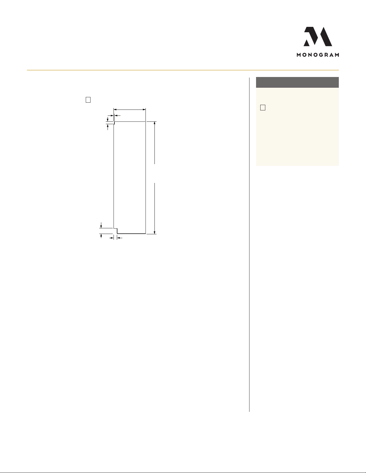
CUSTOM SIDE PANELS
STANDARD INSTALLATION
F
*3"- 4"
(7.6 - 10.2)
*Depending
on installation
height
1 7/8"
(4.8)
24" (61.0)
3/16"
(.5)
2 9/16"
(6.5)
*84"
(213.4)
*Depending
on installation
height
HELPFUL TIPS
F
Side panels must be used
whenever the sides of the freezer
will be exposed. e 1/4" side
panels will slip into the side
case trim. Secure the panels to
the freezer with stick-on hook
and loop fastener strips. Order
the side panels from the ca binet
manufacturer.
For questions about your
appliance, please call 1-800-626-2000.
Product Specication Created 10/19PAGE 4 OF 5
Page 5
"
FRONT VIEW
SIDE VIEW
71 1/2" (181.6)
Finished Width
24" (61.0)
Min. Cutout Depth
24 3/16" (61.4)
2 5/16"
(5.9)
5 1/2"
(13.9)
9"
(22.9)
83 1/2" min
84 1/2" max
(212.1-214.6)
Finished Opening
3 1/2"
(8.9)
W
FRONT VIEW
ELEC.
5 1/2"
(13.9)
9"
(22.9)
3 1/2"
(8.9)
22 3/4"
min
22 3/4"
min
22 3/4"
min
1"
2" min
75 1/2"
(191.8 )
From floor
to bottom
of electrical
area
ELEC.
SIDE VIEW
5"
(12.7)
5"
(12.7)
5"
(12.7)
5"
(12.7)
WATER
3 1/2"
(9.0)
WATER
3 1/2"
(9.0)
DUAL INSTALLATIONS
STANDARD INSTALLATION
A
2 5/16"
(5.9)
9"
(22.9)
WATER
3 1/2"
(9.0)
(2.5)
5 1/2"
(13.9)
ELEC.
83 1/2" min
84 1/2" max
(212.1-214.6)
Finished Opening
(57.8)
5"
(12.7)
DUAL PRODUCT CLEARANCES
To wall
130˚
Door swing
71 1/2" (181.6)
Finished Width
ELEC.
(22.9)
5"
5"
(12.7)
(12.7)
130˚
Door swing
9"
WATER
(57.8)
To wall
24 3/16" (61.4)
5 1/2"
(13.9)
3 1/2"
(9.0)
5"
(12.7)
From floor
of electrical
3 1/2"
(8.9)
75 1/2"
to bottom
(191.8 )
area
(5.1)
Min. Cutout Depth
24" (61.0)
W
To wall
(57.8)
3 1/2
(8.9)
HELPFUL TIPS
A
A separate 115V, 60Hz,
15- or 20-amp power supply is
recommended for each product.
Additional cutout width may be
required when side panels a re used.
B
In a side-by-side installation of a
left-and-right-ha nd door swing
product, 1" cleara nce between
the units is required. Order a
ZKBSN720NSS unification kit
for an integra ted appearance on
2 stainless steel models installed
side-by-side.
C
In a side-by-side installation
with same door swing, allow 2"
minimum cleara nce between
the products to prevent the door
swing interference. Allow 15"
minimum to a wall to achieve
full drawer extension and pa n
removal. Additional cleara nces
are required when using custom
panels a nd handles.
NOTE: ZKBSN720NSS and
ZKBFN720NII unification kits
will not fit this installation.
D
In a side-by-side installation with
right and left door hinges together,
allow 5" minimum cleara nce
between the two products to
prevent one door from striking
the other. Additional cleara nces
required when using custom
panels a nd handles.
NOTE: ZKBSN720NSS and
ZKBFN720NII unification kits
will not fit this installation.
B C
For questions about your
appliance, please call 1-800-626-2000.
5" (12.7) min
D
Product Specication Created 10/19PAGE 5 OF 5
 Loading...