

Page 1

GE Monogram ®
36" Bottom Mount
Refrigerators
Custom
Options Guide
and
Installation
Instructions
With Custom Panel Dimensions
These Monogram refrigerators are
designed to be customized with decorator
door and grille panels. Field installed
panels are required.
Factory installed trim will accommodate
1/4" thick custom panels or optional
Lexan ® and stainless steel panel kits.
Optional trim kits allow an even broader
range of custom appearance options.
Read this bo&_t carefully to accomplish the
desired appearance and to insure a troub_ free
instaUation.
This booklet contains information and
illustrations to demonstrate custom
possibilities. Custom door and grille panel
sizes vary to accommodate the kit being
used. Dimensions for each application are
included and can be faxed or sent to the
and Trim Kit Installation Instructions
Models:
ZIC36N RH
ZIC36N LH
cabinet manufacturer so that the panels can
be constructed accurately.
Page 2
Before you begin - Readthese instructions completely and carefully.
IMPORTANT- Savethese instructions for local inspector's use.
iMPORTANT- OBSERVEALL GOVERNINGCODESAND ORDINANCES.
Note to Installer - Be sure to leave these instructions with the Consumer.
Note to Consumer - Keepthese instructions with your Use and Care Book for future reference.
:t I This appliance musthe properlygrounded.See "Grounding the Refrigerator,"page12.
p_j._l_ Cet appareil dolt_tre correctementmisa la terre.
Ifyou have a question concerning the installation of this
product, call the GEAnswer Center® Consumer
Information Service at 800.626.2000,24hours a day,
7 days a week.
ifyou received a damaged refrigerator, you should
immediately contact your dealer or builder.
Proper installation is the responsibility of the installen
Product failure due to improper installation is not
covered under the GEAppliance Warranty. Seethe
Use & Care Guidefor warranty information.
ForMonogramlocal service in yourarea,
1-800-444-1845.
ForMonogramservice in Canada,
1-888-880-3030
ForMonogramParts andAccessories,call
1-800-626-2002.
Contents DesignInformation
Flushor Semi-Flush Enclosure Installations ...............................................................................................................................3
Enclosure Cutout and ProductDimensions .................................................................................................................................3
Installation Examples,Between Base & Wall Cabinets ...........................................................................................................4
Installation at End-of-Run ...............................................................................................................................................................4
FramelessCabinets ..........................................................................................................................................................................4
Accessory PanelKits .......................................................................................................................................................................4
Models Available ..............................................................................................................................................................................5
Advance Planning Exterior Appearance Options.......................................................................................................................5
Trim KitDescriptions ........................................................................................................................................................................6
Consulter. Mise aterre de re_frige_rateerii, page 12.
• Use this appliance only for its intended purpose,
• Immediately repair or replace electric service
cords that have become frayed or damaged,
• Unplug the refrigerator before cleaning or making
repairs.
• Repairs should be madeby a qualified service
technician.
• II nefaat utiliser cet appareil que pour I'usage
pour leqael il a 6t6 constrait,
• II faut rGparer oa remplacer immGdiatement tout
cordon d'alimentation 61ectriqueeffiloch6 ou
endommag&
• OGbrancher le rGfrigGrateuravant le nettoyage ou
route intervention,
• Les rGparations doivent _tre faites par un
technicien qualifi&
CustomPanel Dimensions
Product and Cutout Information ....................................................................................................................................................7
1/4"Thick CustomPanels or Panels Secured to 1/4"thick backing ........................................................................................8
3/4"Thick Panelswith Supplied Handle, ZKTC36Lor ZKTC36R..............................................................................................9
3/4"Thick Panelswith CustomHandle .......................................................................................................................................10
Side Panel or Filler Options ..........................................................................................................................................................11
Installation Instructions..........................................................................................................................................................12-17
TrimKits
ZGC2TrimKit, Grille Panel FrameAdjustment ..........................................................................................................................18
ZKHC1Trim Kit(for 1/4"Panels), Support for Custom Handles.........................................................................................19-21
ZKTC36L/ZKTC36RTrim Kit,3/4"Custom Panels..................................................................................................................22-27
ZKHTClTrim Kit (for 3/4" Panels),Support for Custom Handles ......................................................................................28-31
ZKHCSS1Trim Kit (for 1/4"Panels),Tubular Stainless Steel Handles .............................................................................32-35
ZKHTCSS1Trim Kit (for 3/4"Pane]s),Tabular Stainless Steel Handles ...........................................................................36-38
ZFClTrim Kit, for side to side installation ..................................................................................................................................39
Page 3
Design Information
Flush or
Semi-Flush
Enclosure
Installations
Advance Planning
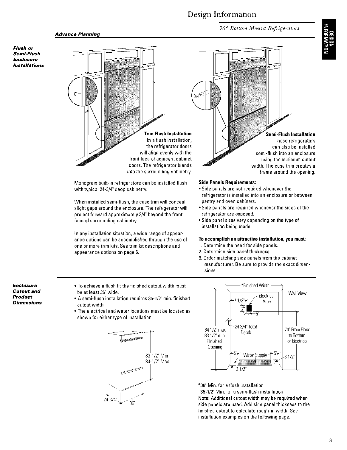
Monogram built-in refrigerators can be installed flush
with typical 24-3/4"deep cabinetry.
When installed semi-flush, the case trim will conceal
slight gaps around the enclosure. The refrigerator will
project forward approximately 3/4" beyondthe front
face of surrounding cabinetry.
In any installation situation, a wide range of appear-
ance options can be accomplished through the use of
one or more trim kits. See trim kit descriptions and
appearance options on page 6.
f
True FlushInstallation
In a flush installation,
the refrigerator doors
will align evenly with the
front face of adjacent cabinet
doors. The refrigerator blends
into the surrounding cabinetry.
36" Bottom Mount ReJi_igerators
I
;emi-FlushInstallation
These refrigerators
can also be installed
semi-flush into an enclosure
using the minimum cutout
width. The case trim creates a
frame around the opening.
SidePanels Requirements:
• Side panels are not required whenever the
refrigerator is installed into an enclosure or between
pantry and oven cabinets.
• Side panels are required whenever the sides of the
refrigerator are exposed.
• Side panel sizes vary depending on the type of
installation being made.
Toaccomplishan attractive installation, you must:
1.Determine the need for side panels.
2. Determine side panel thickness.
3. Order matching side panels from the cabinet
manufacturer. Be sure to provide the exact dimen-
sions.
Enclosure
Cutout and
Product
Dimensions
• To achieve a flush fit the finished cutout width must
be at least 36"wide.
• A semi-flush installation requires 35-1/2" rain.finished
cutout width.
• The electrical andwater locations must be located as
shown for either type of installation.
83-1/2"Min
_/2" Max
24-3/4'_
36"
*FinishedWidth
Electrical
_7 1/_q" / Area
WallView
!|
5
841/2"max
831/2"min
Finished
Opening
*36" Min. for aflush installation
35-1/2"Min. for asemi-flush installation
Note: Additional cutout width may be required when
side panels are used. Add side panel thickness to the
finished cutout to calculate rough-in width. See
installation examples on the following page.
-24 3/4"Total
Depth
_ 1/2"
74"FromFloor
toBottom
ofElectrical
Page 4
Design Information
Installation
Between
Base &
WaH Cabinets
Installation Examples
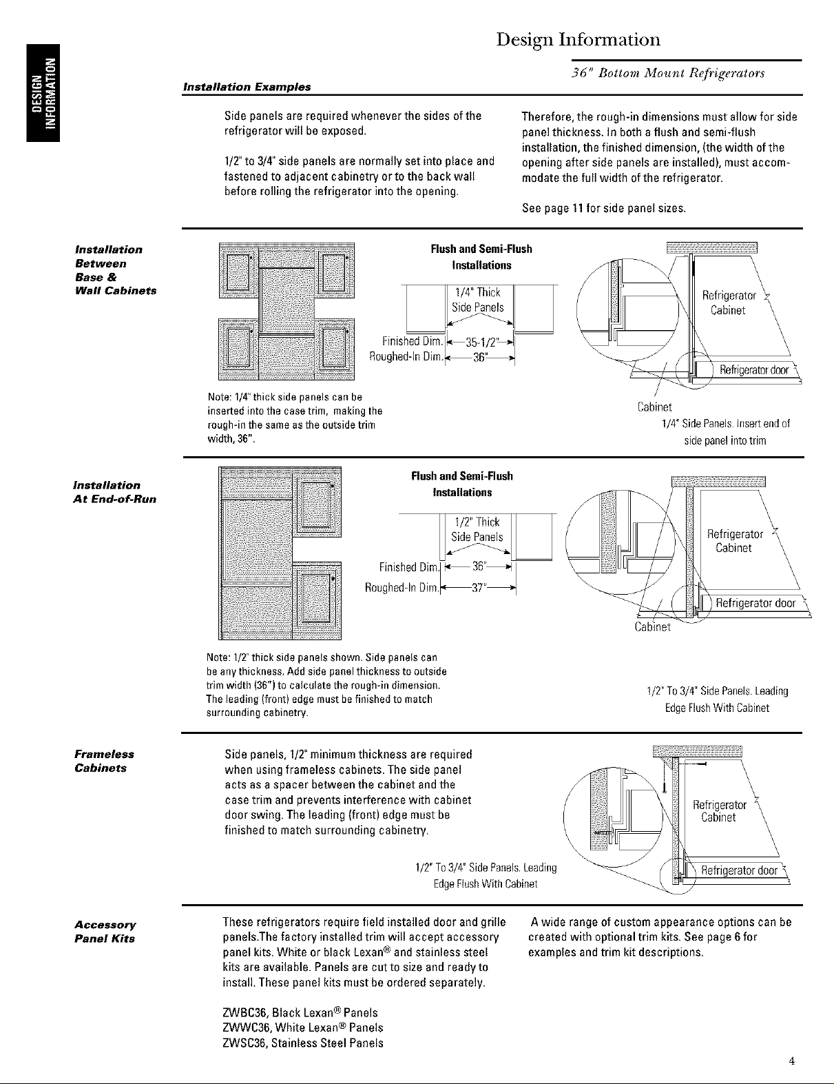
Side panels are required whenever the sides ofthe
refrigerator will be exposed.
1/T to 3/4" side panels are normally set into place and
fastened to adjacent cabinetry orto the back wall
before rolling the refrigerator into the opening.
Note: 1/4"thick side panels can be
inserted into the ease trim, making the
rough-in the same as the outside trim
width, 36",
36" Bottom Mount R@ig_rators
Therefore, the rough-in dimensions must allow for side
panelthickness. In both aflush and semi-flush
installation, the finished dimension, (the width ofthe
opening after side panels are installed), must accom-
modatethe full width of the refrigerator.
See page 11for side panel sizes.
FlushandSemi-Flush
Installations
I II1/4"TNckII I
FinishedDim._35-_ /2"_1
Roughed-InDim._36'_
/_tLy
Cabinet
1/4"SidePanelsInsertendof
sidepanelintotrim
Installation
At End-of-Run
Framaless
Cabinets
FlushandSemi-Flush
. . . 3 _1
FmmhedDml._ 6_,_
Roughed-InRim._37"_
Note: I/2" thick side panels shown. Side panels can
beany thickness, Add side panel thickness to outside
trim width (36")to calculate the rough-in dimension.
The leading (front) edge must befinished to match
surrounding cabinetry.
Side panels, 1/2"minimumthickness are required
when using frameless cabinets. The side panel
acts as a spacer between the cabinet and the
case trim and prevents interference with cabinet
door swing. The leading (front} edge must be
finished to match surrounding cabinetry.
1/2"To3/4"SidePanels.Leading
II1/TThickII I
EdgeFlushWithCabinet
\
Refrigerator
Cabinet
)Refrigeratordoor \
Cabinet
1/2"To3/4"SidePanelsLeading
EdgeFlushWithCabinet
\
\
\
RefrigeratorY\
Cabinet \
Refrigeratordoor\
\
\
\
\
\
\
\
\
\,
Accessory
Panel Kits
These refrigerators require field installed door and grille
panels.Thefactory installed trim will accept accessory
panel kits. White or black Lexan® and stainless steel
kits are available. Panels are cut to sizeand ready to
install. These panel kits must be ordered separately.
ZWBC36,Black Lexan® Panels
ZWWC3g,White Lexan® Panels
ZWSC36,Stainless Steel Panels
Awide range of custom appearance options can be
created with optional trim kits. See page 6 for
examples and trim kit descriptions.
4
Page 5
Design Information
36" Bottom Mount Re/_igerator
Models
available
Advance
planning
exterior
appearance
options
ZIC36NRH
36"wide model with handle onthe left side,the door
swings left to right.
These refrigerators are designed to be customized with
decorator door and grille panels. Field installed custom
door and grille panels are required for these models.
Factory installed trim will accommodate 1/4"thick
custom panels, Lexan® or stainless steel panel kits.
Door and grille panel sizesvary to accommodate the kit
being used. Sizes are provided inthis booklet,
Caution: Maximum panel weight for fresh food door is
50pounds and 30 pounds for freezer drawer panel,
Side panels must be used whenever the sides ofthe
refrigerator will beexposed. Side panel sizes vary
depending onthe installation.
3/4"thick custom panels-Withouttrim kits
A raised panel design, screwed or glued to a 1/4"thick
backing can be used. Seepage 8 for panel sizes and
clearances.
ZIC36NLH
36"wide model with handle on the right side, the door
swings right to left.
Youshould:
1.Select the appearance option.
2. Order the trim kit for that option.
3. Order the custom door and grille panels from the
cabinet manufacturer. The exact dimension for each
trim kit application is provided in this booklet. Find
and pull out the page for your application and fax or
send itto the cabinet manufacturer. The cabinet
manufacturer must havethis information to
construct the panels accurately.
4. Determine the final installation situation and order
matching side panels.
i
5
Page 6
Design Information
36" Bottom Mount R@ig_rator
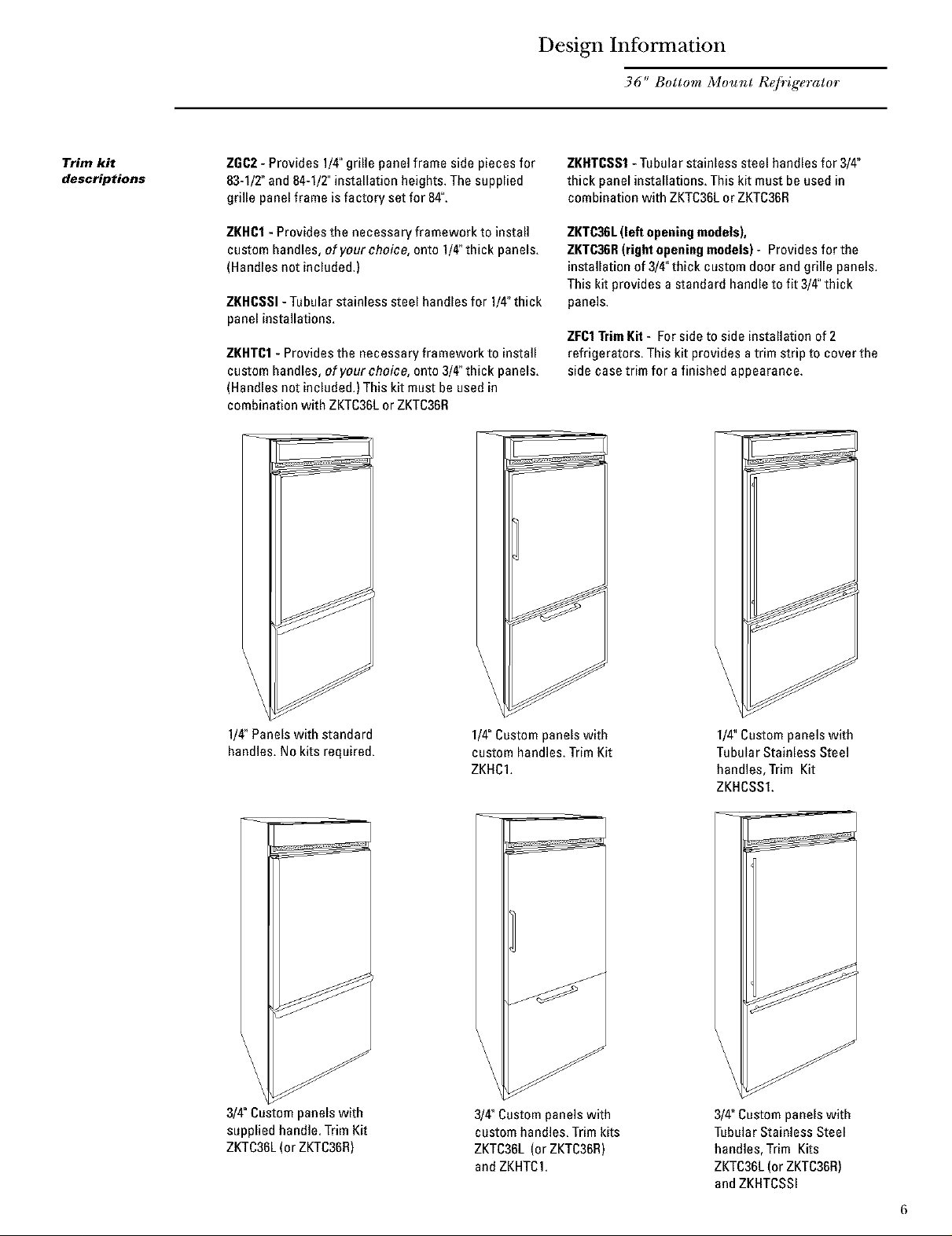
Trim kit
descriptions
ZGC2- Provides 1/4"grille panel frame side pieces for
83-1/2"and 84-1/2"installation heights. The supplied
grille panelframe is factory set for 84".
ZKHCI - Provides the necessary framework to install
custom handles, of your choice, onto 1/4"thick panels.
(Handles not included.)
ZKHCSSI-Tabular stainless steel handles for 1/4"thick
panel installations.
ZKHTC1- Provides the necessary framework to install
custom handles, of your choice, onto 3/4"thick panels.
(Handles not included.) This kit must be used in
combination with ZKTC36LorZKTC36R
ZKHTCSS1- Tubular stainless steel handles for 3/4"
thick panel installations. This kit must beused in
combination with ZKTC36Lor ZKTC36R
ZKTC36L(left openingmodels),
ZKTC36R(right openingmodels)- Provides for the
installation of 3/4"thick custom door and grille panels.
This kit provides a standard handle to fit 3/4"thick
panels.
ZFC1TrimKit - For sideto side installation of 2
refrigerators. This kit provides a trim strip to cover the
side case trim for a finished appearance.
1/4"Panelswith standard
handles. No kits required.
3/4"Custom panels with
supplied handle. Trim Kit
ZKTC36L(or ZKTC36R)
1/4"Custompanels with
custom handles. Trim Kit
ZKHC1.
_ Custompanels with
custom handles, Trim kits
ZKTC36L (or ZKTC36H)
andZKHTC1,
1/4"Custompanels with
TubularStainless Steel
handles, Trim Kit
ZKHCSS1.
3/4" Custom panels with
Tubular Stainless Steel
handles, Trim Kits
ZKTC36L(or ZKTC36H)
andZKHTCSSI
6
Page 7
Custom Panel Dimensions
36" Bottom Mount ReJi_igerators
SideView
243/4"_
_26 3/4"
FrontView 103/4"Max
35"Case_ 10"Min
_6" 0verall'_
841/2"Max
831/2"Min
H/2"
26"
_Finished Width _
Wall View
(not to Scale)
Locate Grounded
Electrical outlet
84 1/2" max
83 1/2" min
Finished
Opening
1/2"
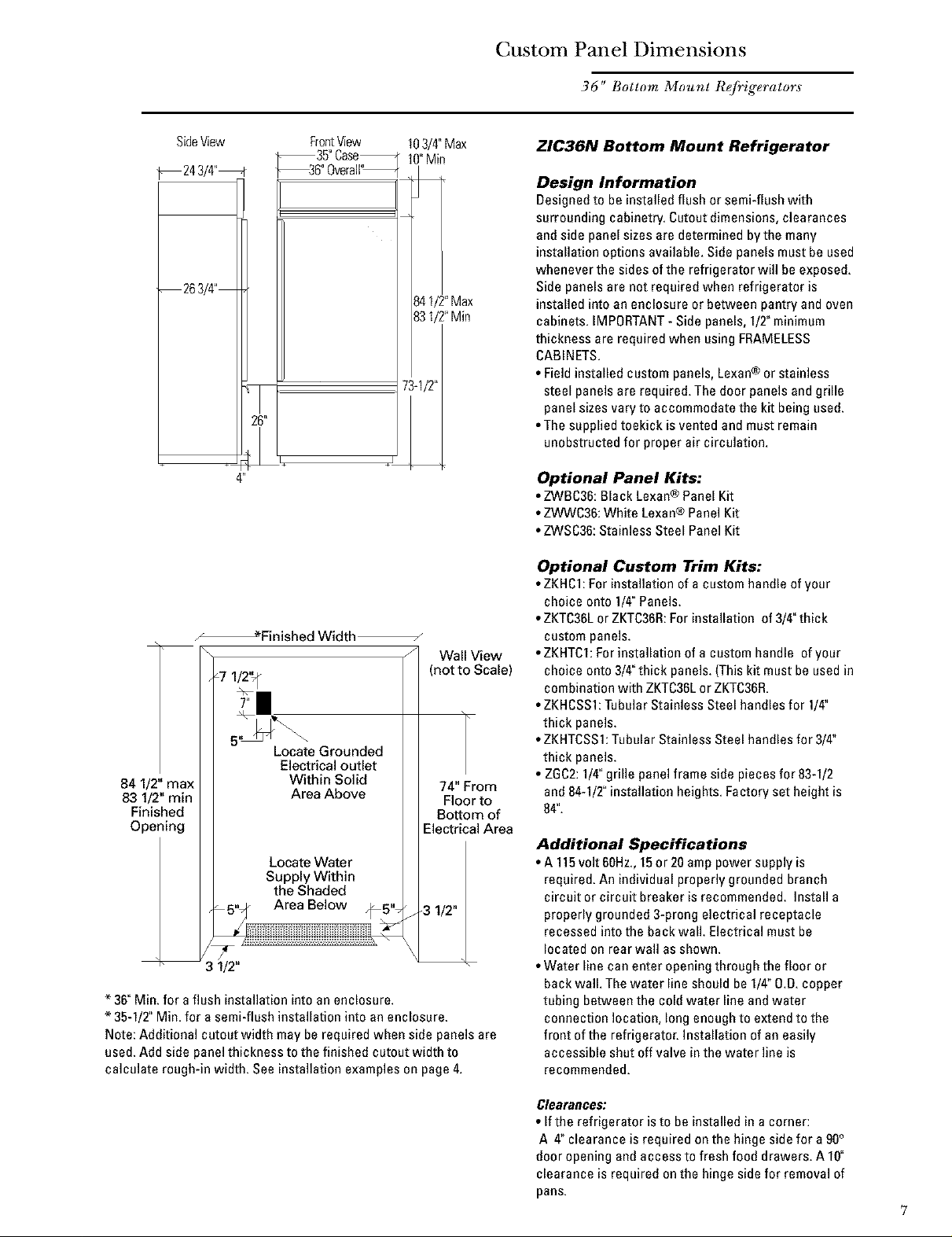
* 36"Min. for aflush installation into an enclosure.
* 35-1/2"Min. for a semi-flush installation into an enclosure.
Note: Additional cutout width may be required when side panels are
used. Add side panel thickness to the finished cutout width to
calculate rough-in width. See installation examples on page 4.
Within Solid
Area Above
Locate Water
Supply Within
the Shaded
_iiii \
74" From
Floor to
Bottom of
Electrical Area
3 1/2"
ZIC36N Bottom Mount Refrigerator
Design Information
Designedto be installed flush or semi-flush with
surrounding cabinetry. Cutout dimensions, clearances
and side panel sizes are determined by the many
installation options available. Side panels must be used
whenever the sides of the refrigerator will be exposed.
Side panels are not required when refrigerator is
installed into an enclosure or between pantry andoven
cabinets. IMPORTANT- Side panels, 1/2"minimum
thickness are required when usingFRAMELESS
CABINETS.
• Field installed custom panels, Lexan® or stainless
steel panels are required. The door panels and grille
panel sizes vary to accommodate the kit being used.
• The supplied toekick is vented and must remain
unobstructed for proper air circulation.
Optional Panel Kits:
• ZWBC36:Black Lexan® Panel Kit
• ZWWC36:White Lexan® Panel Kit
• ZWSC36:Stainless Steel PanelKit
Optional Custom Trim Kits:
• ZKHCl: For installation of a custom handle of your
choice onto 1/4"Panels.
• ZKTC36Lor ZKTC36R:For installation of 3/4"thick
custom panels.
• ZKHTCI: Forinstallation of a custom handle of your
choice onto 3/4"thick panels. (This kit must be used in
combination with ZKTC36LorZKTC36R.
• ZKHCSSI: Tubular Stainless Steel handles for 1/4"
thick panels.
• ZKHTCSSI:Tubular Stainless Steel handles for 3/4"
thick panels.
• ZGC2:1/4"grille panel frame side pieces for 83-1/2
and 84-1/2" installation heights. Factory set height is
84".
Additional Specifications
• A 115volt 6OHz.,15or 20 amp power supply is
required. An individual properly grounded branch
circuit or circuit breskeris recommended. Install a
properly grounded 3-prong electrical receptacle
recessed into the back wall. Electrical must be
located on rear wall as shown.
• Water line can enter opening through the floor or
back wall. The water line should be 1/4"O.D.copper
tubing between the cold water line and water
connection location, long enough to extend to the
front of the refrigerator. Instagation of an easily
accessible shut off valve in the water line is
recommended.
Clearances:
• If the refrigerator is to be installed in a corner:
A 4" clearance is required onthe hinge side for a 90°
door opening and access to fresh food drawers. A 10"
clearance is required on the hinge side for removal of
pans.
7
Page 8
Custom Panel Dimensions
36" Bottom Mount ReJi_igerators
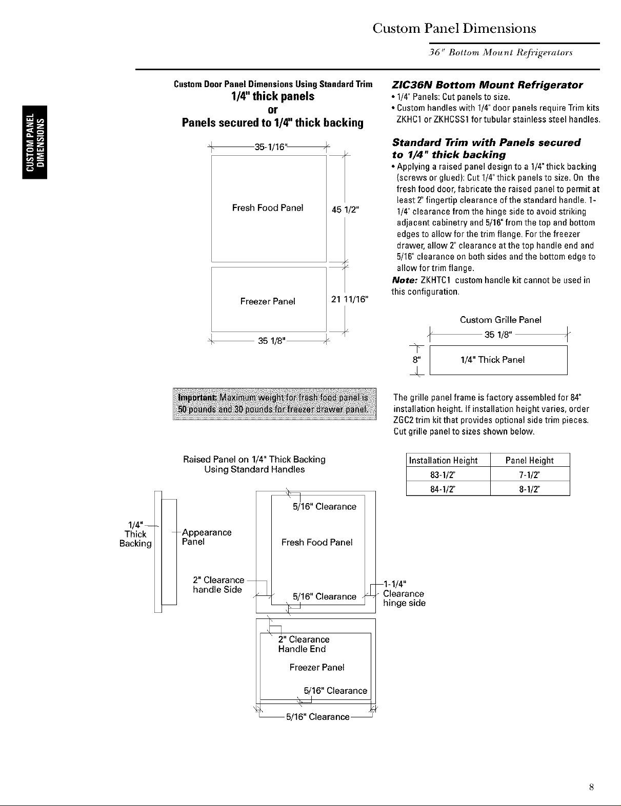
CustomDoorPanel DimensionsUsingStandardTrim
1/4" thick panels
or
Panels secured to 1/4" thick backing
@ 35-1/16 _
Fresh Food Panel 45 1/2"
Freezer Panel
+
35 1/8"
21 11/16"
¢
ZIC36N Bottom Mount Refrigerator
• 1/4"Panels:Cutpanels to size
• Custom handles with 1/4 door panels require Trim kits
ZKHC1orZKHCSSl for tubular stainless steel handles
Standard Trim with Panels secured
to 1/4" thick backing
• Applying a raised panel design to a 1/4"thick backing
(screws or glued): Cut1/4"thick panels to size On the
fresh food door,fabricate the raised panel to permit at
least 2, fingertip clearance of the standard handle 1-
1/4 clearance from the hinge side to avoid striking
adjacent cabinetry and 5/16 from the top and bottom
edgesto allow for the trim flange For the freezer
drawer, allow 2"clearance at the top handle endand
5/16 clearance on both sides andthe bottom edge to
allow for trim flange
Note: ZKHTCl custom handle kit cannot be used in
this configuration
Custom Grille Panel
35 1/8"
8" 1/4" Thick Panel
1/4"-
Thick
Backing
Raised Panel on 1/4" Thick Backing
Using Standard Handles
-Appearance
Panel
2anC/_ar_i_tCee2_
5/16" Clearance
Fresh Food Panel
5/16" Clearance •
2" Clearance
Handle End
Freezer Panel
8/16" Clearance
The grille panel frame isfactory assembled for 84"
installation height If installation height varies, order
ZGC2trim kit that provides optional side trim pieces
Cut grille panel to sizes shown below
Installation Height PanelHeight
83-1/2' 7-1/2"
84-1/2" 8-1/2"
1-1/4"
Clearance
hinge side
5/16" Clearance
Page 9
Custom Panel Dimensions
36" Bottom Mount Refrigerator
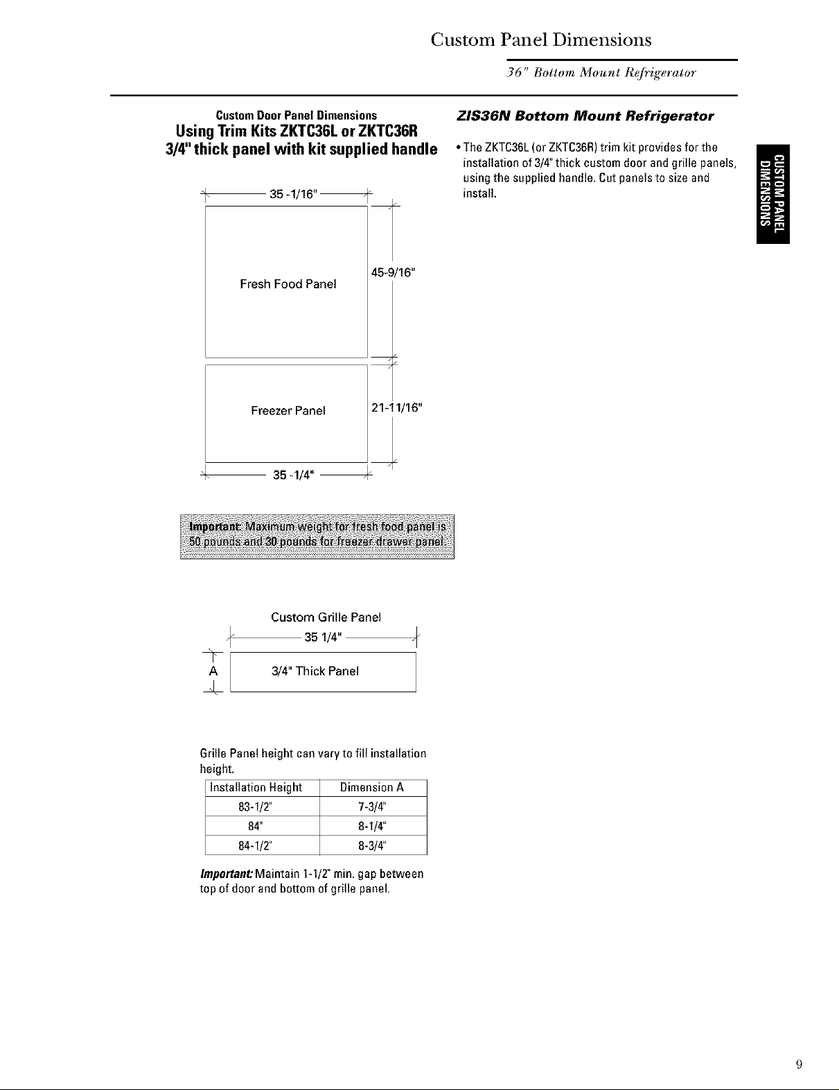
CustomDoorPanel Dimensions
UsingTrim KitsZKTC36Lor ZKTC36R
3/4" thick panel with kit supplied handle
35-1/16"
Fresh Food Panel
+
Freezer Panel
35 4/4"
45-9/16"
/
/
2141/16"
ZIS36N Bottom Mount Refrigerator
• TheZKTC36L(or ZKTC36R)trim kit provides for the
installation of 3/4"thick custom door andgrille panels,
using the supplied handle. Cat panels to size and
install.
Custom Grille Panel
35 1/4"
A 3/4" Thick Panel
J.
Grille Panel height can vary to fill installation
height,
Installation Height Dimension A
83-1/2" 7-3/4"
84" 8-1/4"
84-1/2" 8-3/4"
Important:Maintain 1-1/2"min, gap between
top of door and bottom of grille panel,
Page 10
Custom Panel Dimensions
36" Bottom Mount Refrigerators
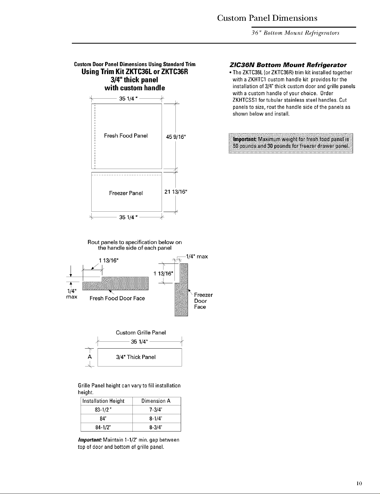
CustomDoor PanelDimensionsUsingStandardTrim
Using Trim Kit ZKTC36L or ZKTC36R
3/4" thick panel
with custom handle
4F 35 1/4 "
Fresh Food Panel 45 9/16"
Freezer Panel
+
Rout panels to specification below on
the handle side of each panel
35 1/4"
ZIC36N Bottom Mount Refrigerator
• The ZKTC36L(or ZI(TC36R)trim kit installed together
with aZKHTC1custom handle kit provides for the
installation of 3/4"thick custom door and grille panels
with a custom handle of your choice, Order
ZKHTCSS1for tubular stainless steel handles. Cut
panelsto size, rout the handle side of the panels as
shown below and install.
1 13/16"
1/4"
max
Fresh Food Door Face
A 3/4" Thick Panel
\
Custom Grille Panel
35 1/4"
&
Grille Panel height can vary to fill installation
height.
Installation Height Dimension A
83-1/2" 7-3/4"
84" 8-1/4"
84-1/2" 8-3/4"
Important:Maintain 1-1/T min. gap between
top of door and bottom of grille panel.
1 13/16"
Door
Face
10
Page 11
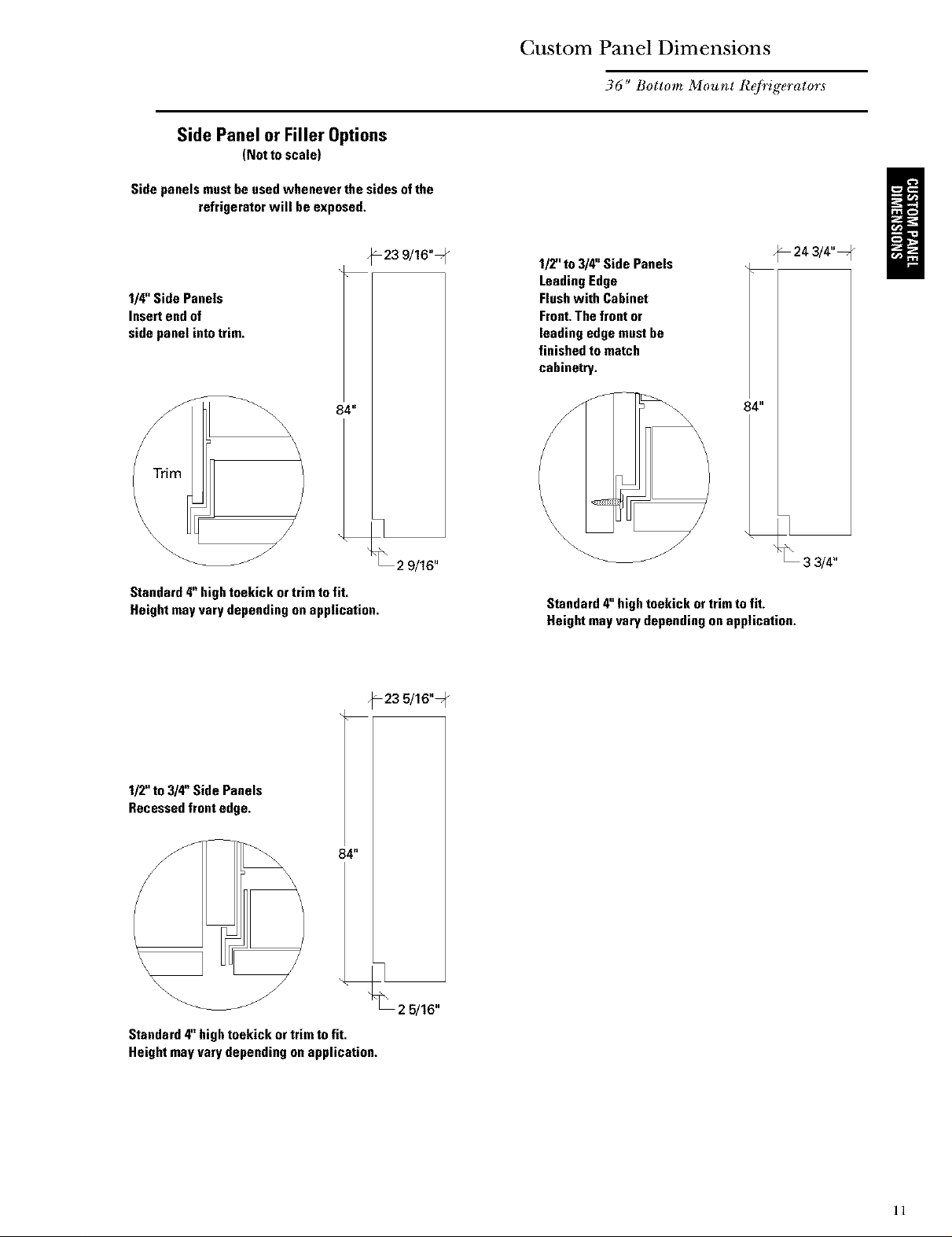
Side Panel or Filler Options
(Notto scale)
Side panelsmast heused whenever the sides ofthe
refrigerator will beexposed.
Custom Panel Dimensions
36" Bottom Mount Refrigerators
114"Side Panels
Insertendof
side panel intotrim,
84"
\\\\
Standard4"hightoekick ortrim to fit,
Height may varydependingonapplication.
_23 9/16"7
-23 5/16" q_
1/2" to3/4"Side Panels
_24 3/4"=
LeadingEdge
Flushwith Cabinet
Front.Thefront or
leadingedge mastbe
finishedto match
cabinetry.
84"
\
Standard4"hightoekick ortrim tofit.
Height mayvarydependingonapplication.
112"to 3/4" Side Panels
Recessedfrontedge.
84"
Standard4"hightoekick or trim tofit.
Heightmayvarydependingonapplication.
25/16"
11
Page 12
Installation
36" Bottom Mount R@ig_rator
Tools
Required
Materials
Required
Hardware
Supplied
Flooring
Grounding
the
Refrigerator
• Tinsnips to cut banding
• Stepladder
• 1-1/2"open-end wrench
• Bucket
• Level
• Appliance Hand Truck
• Tubing cutter
• Water shut-off valve (optional but recommended)
• Water filter WR97XO214(optional but recommended)
• Custom panels for fresh food, freezer drawer, grille
panel
• Special Velcro adhesive strips for 1/4"side panels
• 1/4-1/4union with nuts
• Anti-Tip Mounting Brackets
Forproper installation, this refrigerator must be placed
on alevel surface of hard material that is atthe same
height asthe rest of the flooring. This surface should be
strong enough to support a fully loaded refrigerator.
IMPORTANT- (Please read carefully)
FORPERSONALSAFETY,THIS APPLIANCE MUST BE
PROPERLYGROUNDED.
The power cord of this appliance is equipped with a
three-prong (grounding) plug which mates with a
standard three-prong (grounding) wall receptacle to
minimize the possibility of electric shock hazard from
this appliance.
• 7/15"open-end wrench
• #2 Phillipsscrewdriver
• Stubby Phillips
screwdriver
• Drill and appropriate bits
• 7/16"socket with 3"
extension for ratchet
• Safety glasses
• Side panels
• Hardware for side pane] installation.
• 35"long 2x4for Anti-'tip support
NOTE:Protectthe finish ofthe flooring. Cut a large
section of the cardboard carton and place under the
refrigerator where you are working.
Attaching the adapter ground terminal to a wall
outlet cover screw does not ground the appliance
unless the cover screw is metal, and not insulated,
andthe wall outlet is grounded through the house
wiring. Youshould have the circuit checked by a
qualified electrician to make sure the outlet is
properly grounded.
Havethe wall outlet and circuit checked bya qualified
electrician to makesure the outlet is properly
grounded.
Where a standard 2-prong wall outlet is encountered, it
is your personal responsibility and obligation to have it
replaced with a properly grounded 3-prong wall outlet.
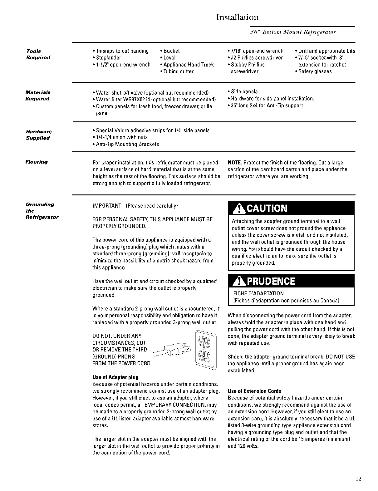
DO NOT,UNDERANY
CIRCUMSTANCES,CUT
ORREMOVETHETHIRD
(GROUND)PRONG
FROMTHEPOWERCORD.
Useof Adapterplug
Because of potential hazards under certain conditions,
we strongly recommend against use of an adapter plug.
However, if you still elect to use an adapter, where
local codes permit, aTEMPORARYCONNECTION,may
be made to a properly grounded 2-prong wall outlet by
use of a UL listed adapter available at most hardware
stores.
The larger slot in the adapter must be aligned with the
larger slot in the wall outlet to provide proper polarity in
the connection of the power cord.
FICHED'ADAPTAT]ON
(Fiches d'adaptation non permises au Canada)
When disconnecting the power cord from the adapter,
always hold the adapter in place with onehand and
pulling the power cord with the other hand. If this is not
done,the adapter ground terminal is very likely to break
with repeated use.
Should the adapter ground terminal break, DONOTUSE
the appliance until a proper ground has again been
established.
Useof ExtensionCords
Because of potential safety hazards under certain
conditions, we strongly recommend against the use of
an extension cord. However, if you still elect to use an
extension cord, it is absolutely necessary that it be a UL
listed 3-wire grounding type appliance extension cord
having a grounding type plug andoutlet and that the
electrical rating of the cord be 15amperes (minimum)
and 120volts.
12
Page 13

Step 1
Remove
Packaging
Refrigerator is much heavier at the top than at the
bottom- be careful when moving. When using a
hand truck, handle from side only.
Le r6frig6rateur est beaucoup plus Iourd en haut
qu'en has.II faut _tre prudent Iors des
d6placements. Si un diane est utilis6, il faut
soulever le r6frig6rateur sur le cOt6 aeulement.
• Removeouter carton.
- Carefully cut banding atthe top and bottom.
• Slide out back corner posts (2).
• Slide carton off top of cabinet.
NOTE:IT IS NOT NECESSARYTO LAYCABINETDOWN
IN ORDERTOREMOVESKID!
• Toremove skid, removethe four 7/16"bolts and their
brackets.
• There are support blocks on the bottom ofthe cabinet
anddoor. They must be removed before sliding unit off
skid or damage will occur.
DONOTATTEMPTTOROLLUNIT OFFSKID.
Installation
36" Bottom Mount Refrigerator
7/1B"Bolt
/
• Carefully, tilt cabinet and slide blocks out from
beneath cabinet, slide unit off skid.
• Removetoekick from the fresh food compartment, set
aside for later installation.
IL NE EAUTPASESSAYERDEFAIREROULERLE
REFRIGI_RATEURPOURL'ENLEVERDEkAY PALETTE.
Step2
_s_H
Wa_rLme
• A cold water supply is required for automatic
icemaker operation. The water pressure must be
between 20 and 120p.a.i.
• Route 1/4"ODcopper tubing between house cold
water line and the water connection location.
• Copper tubing should be long enoughto extend to the
front ofthe refrigerator. Allow enough to accommo-
date bend leading into the water valve.
Shutoffthe mainwater supply.
Turn onthe nearest faucet long enough to clear the line
ofwater.
• install a shut-off valve between the icemaker water
valve and cold water pipe in a basement or cabinet.
The shut-off valve should be located where it will be
easily accessible.
NOTE:It is best to install the valve into a vertical water
pipe. If you install the valve into a horizontal water pipe,
makethe connection at the top or side, rather than at
the bottom, to avoid drawing off any sediment from the
water pipe.
• Drill a 1/4"hole in the water pipe.
• Fasten the shut-off valve to the pipe with pipe clamp.
• Tighten the clamp screws until the sealing washer
begins to swell. Do not over tighten.
• Place a compression nut and ferrule (sleeve} onto the
endof the tubing and connect it to the shut-off valve.
Make sure the tubing isfully inserted into the valve
andferrule is tightened.
• Turn onthe main water supply and flush debris from
the line. Run about a quart of water through the tubing
into a bucket. Shut off water supply at the shut-off
valve.
Floor
CopperTubingJ
SaddleType dnlet End
ShutoffValve
Packing.Nut
ionNut
0utletValve \
Ferrule
(Sleeve}
NOTE: Saddle type shut-off valves are included in
manywater supply kits. Before purchasing, make sure
asaddle type valve complies with your local plumbing
codes,
• Install optional water filter in the water line near the
refrigerator. A water filter is recommended in areas
where water supply contains sand or particles.
Installation instructions are packed with the filter.
13
Page 14

Installation
36" Bottom Mount ReJi_igerator
Step 3
Install
Side Panels
• Side panels are not required when the refrigerator is
installed into an enclosure. Skip this step if you are
installing into an enclosure,
• Side panels are required whenever the sides ofthe
refrigerator will be exposed and when installed
between frameless cabinets. See pages 3and 4.
• Side panel installation will be determined by the
design of the side panel you have previously chosen,
• Side panels must be installed plumb.
Illustration A I
Cabinet
1/4"Side panels - Insert end of side panel into case
trim. Fasten with Velcro strips provided.
Illustration C
• If you choose to use 1/4"side panels, they should be
inserted into the case trim as illustrated. Fasten the
panelsto the refrigerator with Velcro strips (provided)
before setting refrigerator in place. See illustration A.
• 1/2"to 3/4"side panels are normally set into place and
fastened to adiacent cabinetry or the back wall before
rolling the refrigerator into the opening. Seeillustra-
tions B and C.
Illustration B
--- \
\
\
Refrigerator
Cabinet
\
\
Refrigeratordoor\
1/2"to 3/4" Side Panels - Leading edge of side panel is
flush with cabinet front. Fastento the back wall using a
cleat,
\
1/2"to 3/4" Side Panels - Recessed front edge of side
panel. Fasten to adiacent cabinet.
14
Page 15

Installation
36" Bottom Mount R@ig_rator
Step 4
Install
Anti-Tip
Brackets
!_i_r,111kqh_[€llANTI-TIP PRECAUTIONS
he refrigerator is heavy at the top and mustbe
ecured topreventthe possibilityof tippingforward.
PRECAUTIONSCONTRELESBASCULEMENTS
Le r(_frigerateurest beaucoupplusIourd en hautet
ilfaut le maintenir enplace poureviter la
possibilitede sonbasculementversI'avant
• Mount brackets provided using #12or #14wood
screws located 83-1/Z from the finished floon
• Screws must protrude at least one inch into vertical
wall studs.
• Attach a 35"long 2x4 block to brackets as shown,
Roll RefrigeratorIntoOpening
• Gently push refrigerator into opening with hands
against front corners, The cardboard protective pad
should be beneath the refrigerator,
• Roll refrigerator into the opening until it is flush or
semi-flush with adiacent cabinets.
83-1/2"
From
Floor
to
Bottom
ofWood
Block
SideView SideView
_Mounting Bracket
_83q/2" FromFloor
_-- _ WoodScrewsMountedinto
VerticalWoodStuds
Important Note: When the refrigerator is installed under a
soffit or if there is not enough height for this method of
security, use Step 6 as an alternate. The refrigerator must
be secured to prevent tipping.
Step 5
Level
Refrigerator
Step 6
Secure
Refrigerator
to Sides
All models have 4-point leveling. The front is supported
byleveling legs,the rear is supported by wheels.
• Adjust rear wheels beneath the refrigerator to iuat
barely touch the 2x4 block.
• Turn the 7/16"hex nut located above the front wheels.
Turnto raise or lower the refrigerator.
• For front leveling legs, use a 1-1/2"open-end wrench.
• Adjust carefully, the refrigerator should be level and
plumb with cabinetry, and should align with toekick
height.
Noter Whenever possible,
perform this step for
additional anti*tip security.
This step can be used as an
alternate to Step 4, Anti*Tip
bracket installation,
whenever brackets cannot be
used.
When using 1/2"to 3/4" side panels, the front flange of
the case trim is attached to the side panel.
• Openfresh food door to access case trim.
• Drill hole intrim slightly below fresh food opening.
Drive screw through the trim andinto the side panel.
• Follow the same procedure on the opposite side.
HexNI
RearWheets
LevelingLeg
OR
_J
If refrigerator is installed between cabinets with no
side panels or in a custom enclosure, install a spacer
block as shown.
• Openfresh food door to access case trim.
• Drill hole intrim slightly below fresh food opening and
drive screw through the trim and into the spacer
block.
• Follow the same procedure on the opposite side.
15
Page 16

Installation
36" Bottom Mount R@ig_rator
Step 7
Connect
Water
Supply
Step 8
InstaH 1/4"
doorpane_
Checkto be sure that refrigerator power cord is not
plugged into the wall outlet.
• Locate and bring copper tubing to the front of the
cabinet.
• The copper tubing should be just long enough to
reach the coupling. Excesstubing length could interfer
with drawer closing or toekick installation.
• Slip a 1/4-1/4union nut(provided) over both ends of
the copper tubing at the right front leg of the refrigera-
tor and couple the lines.
• Turn on the water to check for leaks.
If you are using3/4"thick custom panels, SKIPTHIS
STEP.See CustomPanel Dimensions pagesfor panel
sizes with ZKTC36Lor ZKTC36Rtrim kit and other kits.
Referto trim kit installation instructions in this booklet.
Freshfood doorpanel:
• Opendoor to 90°stop. Removethe Phillips head
screws from the aluminum trim door handle.
• Remove handle. Retain all screws.
• Slide custom panel into the door trim.
• Replace door handles and secure with original
screws,
I
_k
i
Freezerdrawer panel:
• Slide freezer drawer out about half way.
• Removethe Phillips head screws from the aluminum
trim door handle.
• Lift off handle. Retain screws.
• Slide custom panel into
the drawer trim.
• Replace the drawer handle
and secure with
original screws.
Remove
4 Screws
.I
Install
Original
Screws
16
Page 17

Installation
36" Bottom Mount ReJi'igerator
Step 9
Connect
power
Step 10
Mount
Top Grille
Panel
• Connect refrigerator power cord plug to a properly
grounded receptacle, accessible through the top lelt
side ofthe grille opening.
• Checkto make sure power to refrigerator is on by
opening refrigerator door to see if interior lights are
on.
If you are using 3/4"thick custom panels, SKIPTHIS
STEP. SeeDimensions and Specifications for grille
panel sizes. Order ZKTC36Lor ZKTC36Rand follow the
installation instructions packed with the kit.
The grille panel frame isfactory assembled for an 84"
installation height. If installation height varies, order
ZGC2trim kit which provides optional sidetrim pieces
for 83-1/2"and 84-1/2"heights.
Cut 1/4"thick custom panel to fit the frame,
35-1/8"wide, 8"deep (for an 84" installation).
Toinsert customgrille panel into the frame:
• Removescrews (2 on each top corner) and "L"
brackets on each side.
• Slide panelinto the frame and reassemble.
• Mount the grille panel by dropping into slots on the
case trim.
Top
Case
Trim
RaiseTot
Installation
Height
Step 11
Install
Toekick
• Forshipping purposes, the top case trim is secured at
84"installation height.
Toraise casetrim to 84-1]2"orto lower to 83-1/2"
installation height:
• Loosen 2screws on both sides and raise the top or
lower case trim to meet soffit height or to the top of
adjacent cabinets.
•]]ghten all 4 screws.
J
_iln/.2"
/
g
Important Maintain 1-1/2" min gapbetween top of doors and
bottom of panel frame
• A standard toekick is supplied. Install with 2 screws
provided, adiust to desired height and tighten screws.
Important:The vented toekick must remain unobstructed
for proper air circulation and operation.
17
Page 18

This kit provides optional side trim pieces for the
original grille panel frame to fit 83-1/2" and 84-1/2"
installation heights.
Tochange grille panel size:
• Determine the installation height by measuring the
enclosure from the floor to the underside of soffit.
When there is no soffit, measure to the top ofthe
adjacent cabinets.
• Adjust refrigerator case trim to desired height. See
Product installation.
• Select the side trim pieces for your installation height.
A. Locate original grille panel frame supplied with the
refrigerator.
• Remove8 screws (two on each corner) and "L"
brackets asillustrated.
B.Select correct set of side trim pieces (2 sets
provided).
• Secure new side trim pieces to original bottom trim.
ZGC2 Trim Kit
Grille panel.f_'ame adjustment
E.Mount the assembled panel by dropping into slots on
the case trim.
J
[12_ _Barrel_ Discard
_uts r SideTrim
Pieces
C.Removebarrel nuts from original sidetrim pieces (2
each side).
• Reinstall the barrel nuts on the new side trim pieces
you have selected. Discard original sidetrim.
@
_q9
D.Slide custom panel into front slots.
• Secure the top trim piece to the frame with "L"
brackets andscrews.
ImportantrMaintain 1-1/2" rain, gap between top of door
and bottom of grille panel.
18
Page 19

ZKHCI Trim Kit (for 1/4" Panels)
Support Jbr custom handles
Step 1
Remove
handles
Toolsand materials required:
• #2 Phillipsscrewdriver
• Drill and appropriate bits
• Custom door panels
• Custom Handles
• Safety glasses
Paris List."
A, Fresh food door extrusion {for left hand models}
B, Fresh food door extrusion {for right hand models}
C. Freezerdrawer extrusion
This kit provides the necessary framework to install
custom handles, of your choice, onto 1/4"thick custom
panels. (Handles not included.) The extrusions in this kit
allow the custom handles to be secured to the door
structure, rather than the door panels.
• Select fresh food extrusion for your model, discard
other fresh food extrusion.
Freshfood door:
• Open doorto 90°, Removethe screws from the full
length aluminum handle,
• Retain screws. Discard handle,
Freezerdrawer:
• Slidethe freezer drawer open, about half way.
• Removescrews from thefull-width aluminum handle.
Retain screws. Discard handle.
Righthand door swing models are illustrated in these
instructions, Follow these instructions for left hand
models,
Remove
4Screws
19
Page 20

Step 2
Locate
handle
positions
ZKHC1 Trim Kit (for 1/4" Panels)
!i!_iii!ii_i_iiii!_!_iiiiii!iii_i_i_!:!ij_ii!ii_!i!ii!i!
\
\
\
Support Jbr custom handles
3/4 Min
1-1/2"Max
Freshfood door:
• Slide custom panel into the door trim.
• Temporarily secure the new handle extrusion to the
door using at least 2 screws,
• The custom handles must belocated 3/4"to 1-1/Z
from the edge of the extrusion,
Install
• Determine the desired location of the custom handle
and mark centedinea of the screw holes
• Drill 1/16 pilot hole through the panel until it starts
into the aluminum extrusion This will markthe
matching location for drilling the clearance hole when
assembling the handle, panel and extrusion
Freezerdrawer:
• Slide custom panel into the freezer drawer trim
• Temporarily secure the new handle extrusion to the
drawer using at least 2 screws
• The handle must belocated 3/4" to 11/2 from the
edge of the extrusion
• Determine the location of the custom handle and
carefully mark centerlines of the screw holes
• Drill 1/16"pilot hole through the panel until it starts
into the aluminum extrusion Thiswill mark the
matching location for drilling clearance holes when
assembling the handle, panel andextrusion
20
Page 21

Step 3
Assemble
panel,
extrusion and
handle
Decorator--/ !
DoorPanel
Handle_/ / 3/4" Min.
_"Max.
_Extrusion
ZKHCI Trim Kit (for 1/4" Panels
Support,/or custom handles
Screw
Decorator _" !
Door_-/
Panel
÷1
Freshfood (leer: Freezerdrawer:
• Removethe door extrusion and custom panel. • Removethe handle extrusion and panel.
• Drill 1/16"pilot hole through extrusion. • Drill 1/16"pilot hole through extrusion.
• Drill clearance holes through the panel and extrusion. • Drill clearance holes through the panel and extrusion.
• Assemble the door panel, extrusion and custom handle. "Assemble the door panel, extrusion and custom
• Install screw(s) long enough to pass through the handle.
extrusion, door panel and into the handle. • Install screws(s) long enough to pass through the
• Slide the assembly into the door frame until the new extrusion, door panel and into the handle.
extrusion fits firmly against the steel door. • Slidethe assembly intothe drawer trim until the new
• Reinstall original screws into the door extrusion, extrusion fits firmly against the steel drawer.
• Reinstall original screws into the extrusion.
21
Page 22

ZKTC36L/ZKTC36R Trim Kit
3/4" Custom Panels
Kit Contents
Righthand door swing models are illustrated in these
instructions. Follow these instructions for left hand
models.
Toolsand materials
required:
• #2 Phillips screwdriver
• Drill and appropriate
bits
• Custom door panels
• Patty knife
• Safety glasses
PartsList
A. Toptrim
B.Fresh Food Handle
C,Hinge side trim
D Bottom trim
E.Freezer Handle
ESide Trim
G.Side Trim
H.Bottom trim
l, Support brackets for
custom panels
J. 4-3/8" screws for
support brackets
(2O)
K, Grille support
panel and screws
H
(0)
L Wood screws #6
1/2"flat head
screws (30)
This kit provides for the installation of 3/4"thick custom
door and grille pane]s. Handles are included and must
replace the supplied handles,
F
G
K
Note: if you are using
custom handles, see
ZKHTC1 installation
instructions. For tubular
stainless steel handles, see
ZKHTCSS1 installation
instructions.
22
Page 23

ZKTC36L/ZKTC36R Trim Kit
3/4" Custom Panels
Step 1
Remove
handles
and trim
Freshfood door:
• Open doorto 90°
• Removethe Phillips head screws from the full length
handle, remove handle.
• Openthe doorfully to stop.
• Removethe screws from the aluminum trim, top
bottom, hinge and handle side.
• Retain screws. Discard original trim and handle.
Freezerdrawer:
• Slidethe drawer fully open.
• Lift out top and bottom freezer
baskets,
• There are 2 sets of 4 screws on
the inside of the drawer door,
insert putty knife behind screw
cover and snap off. Retain screw
covers.
• Loosen all screws.
• Carefully, lift off entire drawer
door.
• Place door on a protected surface,
front side down. Take care not to
bend switch plate onthe bottom of
the door.
• Removelight switch plate by
backing out 3 Phillips head
screws. Retain switch plate and
screws.
*Turn the drawer over,front side
up. Removetrim on both sides,
bottom and handle. Retain all
screws.
..--"
Drawer Slides
.
Inside Freezer Drawer
Atta chmentScrews
&==A
Light Switch Plate
T T _
FrontFace Freezer Drawer
LightSwitch Plate
23
Page 24

ZKTC36L/ZKTC36R Trim Kit
3/4" Custom Panels
Step 2
Install
3/4" trim
FreshFoodDoor:
• Attach the new 3/4"trim pieces on the top, hinge side
and bottom using original screws.
FreezerDrawer:
• Attach the new 3/4"trim pieces on the bottom and
both sides.
Front FaceFreezer Drawer
Step 3
Apply panel
support
brackets
• Position support bracket on the back side ofthe fresh
food panel, 14-5/16"from the hinge side. Secure
support bracket to panel with screws provided.
• Position support bracket on the back side ofthe
freezer drawer panel,14-5/16"from the right side.
Secure support bracket to pane] with screws
provided.
1 L 1
BackSideFreshFoodPanel
Side
114-5/16"_ BottomEdge
BackSideFreezerDrawerPanel
-L14-5/16"_ BottomEdge
24
Page 25

ZKTC36L/ZKTC36R Trim Kit
3/4" Custom Panels
Step 4
Install
panels
FreshFoodPanel:
• Place the 3/4"thick panel on the bottom trim with
support bracket tabs inserted into slots. Push the
panel back against the steel door, flush with hinge
side trim.
• Open the door fully.
• Carefully drill 4starter holes using a small drill bit,
through the backside of the trim at the top.
• Install original screws through the trim and into the
panel to secure the panelto the door.
• Drill 4 starter holes through the hinge side and 4
through the bottom trim. Install original screws.
Freezerpanel:
• Place the 3/4"thick panel onto the door with the
support bracket tabs inserted into slots. Thesides of
the panel should be flush with trim on both sides.
• Turn door over, panel side down. Attach the panel to
the sides and bottom by installing screws through the
back of the trim and into the wood panel.
• Reinstall lightswitch plate to the bottomtrim with
original screws.
/ /"
/
Insert support bracket tabs
into slots on bottom trim
Inside Freezer Drawer
/"
LightSwitch Plate
25
Page 26

ZKTC36L/ZKTC36R Trim Kit
3/4" Custom Panels
Step 5
Install
handles
Step 6
Adjust
grille
panel height
• Install new fresh food door handle using original
screws.
• Place assembled drawer door onto freezer slides.
• Tighten screws and snap on screw covers.
• Install new freezer drawer handle with original
screws.
• For shipping purposes, the top case trim is secured at
the 84"installation height.
• Loosen 2 screws on both sides ofthe case trim and
raise or lower trim to meet soffit height, from 83-1/2"to
84-1/2".
• Tighten all 4 screws.
Important: Maintain 1-1/Z' min. gap between top of door
and bottom of grille panel,
Install
4Screws
Top
Case
_im
Installation
Height
Step 7
Secure 3/4"
panel to
grille panel
support
• Secure the grille panel support to the back side of the
3/4" custom panel with #6 screws,
• Be sure the lip ofthe support is over the top of the
wood panel.
PanelSupport
J
f_
f
26
Page 27

ZKTC36L/ZKTC36R Trim Kit
3/4" Custom Panels
Step 8
Install
grille panel
• Install four of the six larger undercut screw so that the
top of the screws are 1/16"from the surface of the
support.
• Attach the assembled panelto the refrigerator by
inserting the four protruding screws into the brackets
on each side of the grille opening.
27
Page 28

ZKHTC1 Trim Kit (For 3/4" Panels)
Support,/or Custom Handles
Kit Contents
Righthand door swing models are illustrated in these
instructions. Follow these instructions for left hand
models.
Toolsand materials required:
• #2 Phillips screwdriver
• Drill and appropriate bits
• Custom door panels
• Custom handles
• Safety glasses
Note:This kitmust beused incombination with ZKTC36L
or ZKTC36Rtrim kitfor 3/4"paneltrim.
Part List:
A. Fresh food handle extrusion (for left hand models)
B.Fresh food handle extrusion (for right hand models)
C. Freezerdrawer extrusion
This kit provides the necessary framework to install
custom handles, of your choice, onto 3/4"thick
decorator door panels. (Handles not included.) The
door extrusions allow the custom handles to be
secured to the door structure, rather than the door
panels.
• Select fresh food handle extrusion for your model,
discard other fresh food extrusion.
Before
you begin
3/4" custom door panels must be routed to accommo-
date these door handle extrusions. Routthe panels as
illustrated, 1/4"deep, and 1-13/16"wide onthe handle
side of the fresh food panel and the top end of the
freezer panel.
Referto installation instructions for ZKTC36Lor
ZKTC36Htrim kit for 3/4"custom panels:
• Follow Step 1 to remove the standard aluminum trim.
• Follow Steps 2 and 3 to attach new 3/4"trim pieces
andto install panel support brackets.
FreshFoodPanel
FreezerDrawerPanel
,U1-13/16"
1/4" Max._ BackSide
HandleSide
Important: Optimal final appearance depends on careful
routing depth, Do not exceed 1/4" routing depth
Handle
End
28
Page 29

Step 1
Temporarily
mount door
pane_
Freshfood door:
• Place the prepared 3/4"custom door panels on the
bottomtrim with support bracket tabs inserted into trim
slots.
• Pushthe panel back against the steel door, making
surethe panel is flush with the hinge side trim.
• Secure the panel to the trim temporarily bydriving 2
screws through the backside of the trim atthe top.
• Slidethe handle extrusion in between the panel and
steel door.
• Temporarily secure the extrusion to the door with 2
screws.
NoterThe freezer drawer door should be removed as shown
in the installation instructions for the ZKTC36 kit. Follow the
instructions in Step 1to remove the door.
ZKHTC1 Trim Kit (For 3/4" Panels)
Support,/or Custom Handles
I
Insert support bracket tabs
into slots on bottom trim
Inside Freezer Drawer
%,
Freezerdrawer:
• Place the prepared 3/4"custom panel onthe bottom
trim with support bracket tabs inserted into the trim
slots.The panel should beflush with trim on both sides.
• Secure the panel to the trim temporarily bydriving one
screw through the back side of each sidetrim.
• Temporarily mountthe assembled drawer door onto the
drawer slides. This will help to determine the handle
location.
Note: Be careful not to bend light switch plate on the
bottom of the door.
• Slidethe handle extrusion in between the panel and
steel door.
• Temporarily secure the extrusion to the door with 2
screws.
29
Page 30

ZKHTC1 Trim Kit (For 3/4" Panels)
Support jbr Custom Handles
Step 2
Locate
position
of handles
Freshfood door:
• Determine the locationof the custom handles
and carefully mark centerlines ofthe screw
holes.The handles must be located 3/4" to
1-1/Z from the edge of the extrusion.
• Drill 1/16"pilot hole through the panel until it
starts into the aluminum extrusion. This will
mark the matching location for drilling a
clearance hole when assembling the
extrusion, panel and handle.
FreezerDrawer:
• Follow the same procedures as for the fresh
food door.
3/4" Min.
1-1/2"Max.
/" \
Step 3
Assemble
panel,
extrusion and
handle
Freshfood door:
• Removethe handle extrusion, the 2 temporary
screws and custom panel.
• Drill 1/16"pilot hole through extrusion.
• Drill clearance holes through the panel and
extrusion.
• Assemble the panel, extrusion and custom handle.
• Install screw(s) long enoughto passthrough the
extrusion, door panel andinto the handle.
Freezerdrawer:
• Removethe handle extrusion and entire assembled
drawer door.
• Remove panel from drawer door.
• Drill clearance holes through the panel and
extrusion.
• Assemble the panel, extrusion and custom handle.
• Install screw(s) long enoughto passthrough the
extrusion, door panel andinto the handle.
Screw\. I
I
I
1-f/2" Max.
3O
Page 31

Step 4
Mount
assembled
panels
ZKHTC1 Trim Kit (For 3/4" Panels)
Support,/br Custom Handles
Install
4Screws
J_ _J
Fresh food door:
• Place assembled panel ontothe bottom trim with
support bracket tabs inserted into slots.
• Pushthe panel back against the steel door with
handle extrusion flush to handle side of the door.
• Open doorfully to stop.
• Install original screws atthe top, hinge side and
handle side.
Freezerdrawer:
• Mount assembled door with panel onto freezer slides.
• Install original screws along the top handle extrusion.
31
Page 32

ZKHCSSI Trim Kit (For 1/4" Panels)
Tubular Stainless Steel Handles
Right hand door swing models are illustrated in these
instructions. Follow these instructions for left hand
models.
Note: It is best that 2 people install this kit,
Toolsand materials required:
• #2Phillips screwdriver
• Drill and appropriate bits
• Customdoor & drawer panels
• Safety glasses
• Center punch
• Masking tape
• Hammer
• Pencil
• 1/2"thick 12"x 12"rain. piece of plywood to protect
floor when drilling
• For stainless steel panels, wear glovesto protect
against sharp edges.
Parts List:
A. Handle extrusion(for left hand models)
B. Handle extrusion (for right hand models)
C.Freezer handle extrusion.
D. Freshfood and freezer door handles
E.6 Spacer rings (for Stainless Panels ONLY)
(4 required, 2 extra)
E4 Handle standoffs
G.6 Screws for mounting handle standoffs
(4 required, 2 extra)
H. 6Set screws (4 required, 2 extra)
I.3/32"Allen wrench for set screws
This kit provides for the installation of Stainless Steel
handles on 1/4"thick decorator door panels. The door
extrusions allow these custom handles to besecured
to the door structure, rather than to the custom panels.
• Select fresh food extrusion for your model, discard
other fresh food extrusion.
B
C
F
zzm
Step 1
Remove
handles
Freshfood door:
• Openfresh food door to 90%Removethe
screws from the full-length handle.
• Retain screws, discard handle.
Freezerdrawer:
• Slidethe drawer open about halfway.
• Carefully removethe Phillips head screws
from the top trim. Lift off handle.
• Retain screws, discard handle.
Remove
4 Screws
..
.I
32
Page 33

ZKHCSSI Trim Kit (For 1/4" Panels)
Tubular Stainless Steel Handles
Step 2
Match
handle
extrusions
to handle
See Step 2A
for Stainless
Steel panels
• Cut a piece of corrugated to use as a pad to protect
the panelfinish. Use 1/2"thick section of plywood to
protect flooring when drilling.
• Place custom panels on the pad, appearance side
down.
Freshfeed door:
• Onthe back side of the panel - at the handle side,
measure and mark 1/4"below thetop edge of the
panelwith a pencil.
• Slip panels into new extrusion on the handle side of
the panels.
• Align the extrusion at the pencil mark, 1/4"below the
top of the panel.
• Tape the extrusion to the panel to prevent movement.
• Center punch and drill 1/8"pilot holes through the
holes in the extrusion and into the panel.
• Turn panel over. Onthe appearance side, use 9/32"bit
to enlarge clearance hole.
Freezerdrawer:
• Lay panel onthe pad, appearance side down.
• Slip panel into the new extrusion onthe handle end.
• The panel should be even with both endsof the
extrusion. Tape panel to extrusion to prevent
movement.
• Center punch and drill 1/8"pilot holes through the
holes inthe extrusion and into the panel.
• Turn panel over. Onthe appearance side, use 9/32"bit
to enlarge clearance hole.
IMPORTANT'. Hole locations must be exact to accept
handle standoff and handle assembly,
Decorator
Door--/
Panel
_Extrusion
I
I
33
Page 34

ZKHCSSI Trim Kit (For 1/4" Panels)
Tubular Stainless Steel Handles
Stop 2A
Step 3
Install
standoffs
onto handles
Ifyon are installing those handlesonto Stainless
Steel Panels:
Use extreme caution if youare drilling through
stainless steel panels. Stainless steel panels must be
handled gently. Do not kneel on stainless steel panels.
Itwill leavea permanent dent. Donot remove protec-
tive plastic covering until final installation.
Freshfood door:
• Place supplied filler panel (corrugated) onfloor to use
asa pad.
• Onthe back side of the panel - at the handle side,
measure and mark 1/4"below thetop edge of the
panel.
• Slip panel into the new extrusion, flush against inner
edge, on the handle side.
• Align extrusion to pencil mark as shown in Step2.
Mark each screw hole location with pencil.
• Place a handle standoff onto attachment posts along
the handle. Position the set screw hole onthe
standoff to point to the floor.
• Install set screws into the bottom of each standoff,
using the Allen wrench provided. The standoff should
betight against the handle.
• Tape extrusion to panel to prevent movement.
• Place panel on plywood section, appearance side
down. Be sure plywood is clean without nicks and
burrs. Center punch at each screw hole location.
• Drill 1/8"pilot hole. Use 9/32"bit to enlarge clearance
hole.
• Measure and cut a 2"wide strip, top to bottom off the
corrugated panels. This will allow roomfor spacer
rings between the stainless panel and extrusion.
Freezerdrawer:
• Place supplied filler panel (corrugated) on floor to use
as a pad.
• Onthe back side of the panel - at the handle end,
slip panel into the new extrusion, even end to end.
• Mark each screw hole location with pencil.
• Follow the same procedure as for fresh food door.
Step 4
Install
handles
and panels
See Step 4A
for stainless
steel panels
Freshfood door:
• Slide panel into the door trim. Leave about 4" ofthe
panel exposed to allow room to install the handle
extrusion.
• Place extrusion onto the back side of the panel, install
mounting screws through the extrusion and just
through the panel.
• Drive screw part way through the top standoff, then
part way through the bottom standoff.
• Drive both screws until the handle is tight against the
panel.
• Removetape.
• Slidethe assembled panel into the door trim until the
extrusion fits firmly against the steel door. Reinstall
original screws into the extrusion.
Freezerdrawer:
• Slide panel into the drawer trim. Leave about 4"of the
panel exposed to allow room to install the handle
extrusion.
• Place extrusion onto the panel, install mounting
screws through the extrusion and just through the
panel.
• Drive screw part way through one standoff, then part
way through the other standoff.
• Drive both screws until the handle is tight against the
panel.
• Removetape.
• Slidethe assembled panel down until the extrusion
fits firmly against the top of the drawer. Reinstall
original screws into the extrusion.
Decorator
D°°iPanel=_
sciw
J
34
Page 35

Step 4A
Install
handles and
panels
ZKHCSSI Trim Kit (For 1/4" Panels)
Tubular Stainless Steel Handles
Screw
Stp_n,e;_iat_ SRP__ - Extrusi°n
Handle_--;
• Crimp top and bottom edges of corrugated.
• Slide corrugated into door and drawer trim, Leave
about 1/4"gapbetween edge of corrugated and
hinge side trim ofthe door and 1/4"gap above bottom
trim ofthe drawer,
• Place extrusion onto panel. Use a pencil to punch
hole in tape covering spacer rings and align with
screw holes
• Install mounting screws through the extrusion and
panel
• Drive screw part way through the top standoff, then
Note: Panels have a protective plastic covering. Peel
away just enough to allow panel to slide into trim and to
clear handle mounting screws. The plastic covering will
keep the panels clean during the installation process.
Be sureto maintain 1/4"gap between corrugated and
hinge side or bottom trim.
Freshfeed deer:
• Slide panels into the door trim. Leaveabout 4" ofthe
panel exposed to allow room to install the handle
extrusion,
• Place a spacer ring over each ofthe 2 screw holes
part way through the bottom standoff
• Drive both screws until the handles are tight against
the panel
• Slide the assembly into the door trim until the
extrusion fits firmly against the steel door
• Reinstall original screws into the door extrusion
Freezerdrawer:
• Follow the same procedure to install spacer ring,
mounting screws and handle to extrusion as de-
scribed for fresh food panel
• Slide the assembly down into the door trim until the
extrusion fits firmly against the steel drawer
• Reinstall original screws into the door extrusion
on the extrusion. Usetape to hold in place,
Raised Panel on 1/4"Thick Backing:
A raised panel design secured to a 1/4"thick backing
RaisedPanelon 1/4"Thick Backing
UsingStandardHandles
(screwed or glued) can be used with this handle kit.
• Cutthe 1/4"thick panels to size, _]
• Fabricate the raised panel to allow 14/4" clearance 1/4" __Appearance
from the hinge side ofthe fresh food panel to avoid Thick Panel
striking adjacent cabinetry, Backing
• Allow 5/16"clearance atthe other edges to allow for _ 5/16"
thetrim flange, [_ Clearance ,
• Total panel thickness should notexceed 3/4", u handleSide
• Countertops adjacent to the refrigerator installation r
should be mitered 45°, 5/16"
Clearance
HandleEnd
Note: Longer Screws, obtained locally, will be required to
accommodate panel thickness. Use stainless steel
#10_32x1-1/4" truss Phillips head screws.
5/1ffClearance
FreshFoodPanel
5/1ff Clearance
FreezerPanel
5!1651earance
5/16"Clearance
1-1/4"
Clearance
hingeside
35
Page 36

ZKHTCSSI for 3/4" panels
Tubular Stainless Steel Handles
Kit
Contents
Right hand door swing models are illustrated in these
instructions. Follow these instructions for left hand
models.
This kit provides for the installation of Stainless Steel
handles on3/4"thick decorator door panels. The door
extrusions allow these custom handles to be secured
to the door structure, rather than to the custom panels.
• Select fresh food extrusion for your model, discard
other fresh food extrusion.
Toolsand materials required:
• #2 Phillips screwdriver
• Drill and 1/8",9/32" bits
• Custom door panels
• Safety glasses
• Center punch
• Masking tape
• Hammer
• Pencil
Paris List:
A. Handle extrusion (for left hand models)
B.Handle extrusion (for right hand models)
C. Freezerdrawer handle extrusion
D.2Stainless tubular handles
E.4 Handle standoffs
E6 Screws for handle standoffs
(4 required, 2 extra)
G.6 Set screws (4 required, 2 extra)
H.3/3Z Allen wrench for set screws
This kit must be used in combination with ZKTC36,trim
kit.
Note:It is best that 2people install this kit.
Before
you begin:
• 3/4" custom panels must be routed to accommo-
datethese handle extrusions. Routthe panels
asillustrated, 1/4"deep, and 1-13/16"wide, top
to bottom on the handle side.
• Follow the instructions inthe ZKTC36R(or
ZKTC36L)to install trim onto the fresh food and
freezer drawer. Discard the handles supplied
with that kit.
• Continue the instructions inthe ZKTC36R(or
ZKTC36L)trim kit to install support brackets to
the bottom of the fresh food and freezer panels.
FreshFoodPane[
FreezerDrawerPane[
Handle
End
÷
Handle Side
IMPORTANT:Optional final appearance depends on
careful routing depth. Do not exceed 1/4"routing depth.
36
Page 37

ZKHTCSS1 for 3/4" Panels
Tubular Stainless Steel Handles
Step 1
Match Handle
Extrusions
to Panels
• Cut a piece of corrugated to use as a padto protect
the pane] finish. Additional material maybe required
to protect flooring when drilling.
• Place custom panels onthe pad, appearance side
down.
Nete: If panels are wood, besure to note which end is
the top sothat wood grain is in the correct direction on
both panels.
FreshFoodPanel:
Select fresh food handle extrusion for your model, left
or right side extrusion.
• Place extrusion against the handle side of the fresh
food panel.
• Align the extrusion evenlywith the top and bottom of
the panel.
• Tape the extrusion to the panel to prevent movement.
• Center punch and drill 1/8"pilot holes through the
holes in the extrusion and into the panel.
• Turn panel over. Onthe appearance side, use9/32" bit
to enlarge clearance hole.
FreezerPanel:
• Place extrusion against the handle end of the freezer
drawer panel.
• Align the extrusion evenly, side to side.
• Tapethe extrusion to the panel to prevent movement.
• Center punch and drill 1/8"pilot holes throughout the
holes in the extrusion and into the panel.
• Turn panel over. Onthe appearance side, use9/32" bit
to enlarge clearance holes.
AlignExtrusionEven
With Panel
Extrusion
EvenWith
Panel
Note,"Hole locations must be exactto accept handle
standoff and handle assembly.
Step 2
Install
Standoffs
onto Handles
• Place a handle standoff on each attachment post on
the handle. Position the screw hole on the standoff
to point to the floor.
• Install set screws into the bottom of each standoff,
using the Allen wrench provided. The standoff
should betight against the handle.
_Screw
_Wrench
37
Page 38

ZKHTCSS1 For 3/4" Panels
Tubular Stainless Steel Handles
Step 3
Install
mounting
screws
and handles
Step 4
Install
Assembled
Panels
FreshFoodPanel:
• Start mounting screws through the extrusion and iust
through the custom panel.
• Stand panelup on the hinge side and hold to access
the appearance side. Place handle against mounting
screws on the appearance side, drivetop screw from
the back ofthe extrusion partially into the standoff.
• Drive second screw partially into the standoff,
alternate back to the top until the handle istight
against the door.
FreezerDrawer Panel:
• Follow the same procedureto assemble handle to
panel,
It is best thet 2 people perform this step.
FreshFoodPanel:
• Place assembled panel onto the bottom door trim
with support bracket tabs inserted into slots.
• Push and hold the panel back against the steel door
with door handle extrustion flush to the handle side
of the door.
• Reinstall original screws into the door extrusion.
• Open the door fully to stop.
• Instag screws atthe top, and hinge side.
Note:The freezer drawer panel should be removed
as shown in the installation instructions for the
ZKTC36kit. Follow the instructions in Step 1to
remove the door.
FreezerDrawer Panel:
•Place the assembled pane] onto the bottom trim
with support brackets inserted into slots. The panel
should beflush with trim on both sides.
• Secure the panel to the trim at the bottom and both
sides.
• Mount the assembled drawer panel onto the freezer
slides. Tighten all screws.
• Install 4screws into the top of the handle extrusion
and into the door.
Install
4Screws
38
Page 39

ZFC1 Trim Kit
For the ultimate in convenience, install two refrigerators
side to side.
This trim kit includes 6 foam spacer pads to fill the gap
between the refrigerator side case trims. Forafinished
appearance, a trim strip is provided to conceal the case
trim ofthe two refrigerators.
Ifyou are installing into an enclosure, provide a 72"wide
opening. If you are installing where the sides of the
refrigerators will be exposed, allow additional width for
any side panels used.
• Apply foam spacer pads evenly to the side of one
refrigerator as shown.
Side to Side Installation
J
D a_I
• Slide second refrigerator into position.
• Check to besure both refrigerators are level. If they
are not level, anobvious gap can be seenbetween
the side trims. Adjust leveling legs if needed. Slight
gaps will be concealed with the trim strip.
• Open both fresh food doors to access side trim.
• The U-shape trim will overlap the side case trim of
both refrigerators.
• Set the top case trim (see page 17)to installation
height.
• Hold trim strip against top end of case, at the point
where case overlaps to the bottom of case trim. See
illustration.
• Mark length with a pencil.
• Trim excess length.
• Starting at the top, press trim strip over case trims of
both refrigerators.
• Continue pressing about half way down. Slide open
freezer drawers and continue pressing trim until you
reach the bottom of the strip.
D D.
n s j
CaseTrim
39
Page 40

Note: While performing installationsdescribed in this book,
safety glasses or goggles should be worn,
"l_ obtain spec!fic i_zJbrmation cor_cernin E l_r_y
Monogram product or service, caa GE Ar_sw_ Cente_
consumer b_lbrmatior_ service at 800.626.2000-a_y
time, day or nik,ht.
bbr Monogram '_' Ncal semice ir_your area, caa
1-800-444-1845.
Note: ProdHct improvement is a continuing endeavor at
General Electric. Therefore, materials, appearance and
specifications are su!_iect to change without notice.
Q Monogram
Genera[ Electric Compa_V
Louisville, KY40225
Pub. No. 49-60000-3
7999GEAppliances
Printed in U.S.A.(N0381) 3/99
5A 95020-02
 Loading...