

GE ZGP48 Series, ZGP304 Series, ZGP36 Series, ZGP30 Series Installation Instructions Manual
Page 1
Installation
Instructions
Convert Natural Gas to LP Gas Operation
Convert LP Gas to Natural Gas Operation
WARNING: This conversion
must be performed by a qualified installer
or gas supplier in accordance with the
manufacturer’s instructions and all codes
and requirements of the authority having
jurisdiction. Failure to follow instructions
could result in serious injury or property
damage. The qualified agency performing
this work assumes responsibility for the
conversion.
WARNING: The rangetop, as
shipped from the factory, is set for use with its
intended gas. If you wish to use your rangetop
with the alternate gas, you must first
replace the orifices and convert the pressure
regulator.
WARNING: The following
adjustments must be made before turning
on the burner. Failure to do so could result in
serious injury. Be sure pressure regulator has
been converted as described in Step 2.
TOOLS YOU NEEDED FOR CONVERSION
Safety Glasses
Small Flat-Head Screwdriver
(2 to 2.4 mm or 3/32” tip size,
60 mm long)
Crescent Wrench
1/4” and 7mm Nutdrivers
7/16” (11 mm)
Open End Wrench
Small Pliers
1/2” Deepwell
Socket Wrench
Philips
Screwdriver
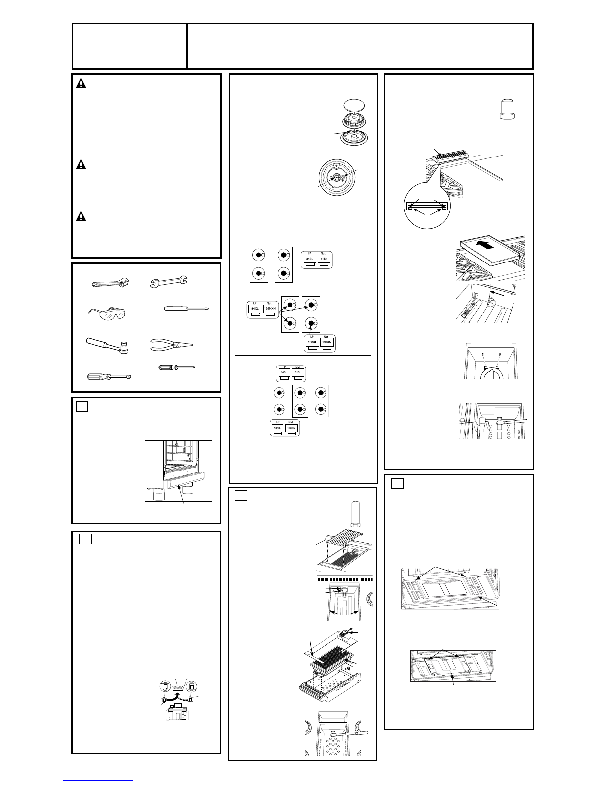
1
ORIFICE HOLDER
The range orifice holder is located behind the front
access panel at the bottom of the range. Remove
the door(s) (See instructions on Page 10) and the
screws on the top and
bottom of the front access
panel. Remove the front
access panel to access the
orifice holder.
Additional orifices may
be present. Use only the
orifices specified in the
instructions for your range
or rangetop.
2
CONVERT THE REGULATOR(S)
Disconnect all electrical power at the main circuit
breaker or fuse box.
A. Shut off the gas supply by closing the manual
shut-off valve on the unit or by the wall.
B. Move the range out in order to access the
rear of the unit.
C. Remove the range back to access the regulator(s)
-
(1) on 30” & 36” ranges and (2) on 48” ranges.
D. Convert the pressure regulator(s):
• Unscrew the cap with plunger.
• Place your thumb against flat side of the
plunger and press down to snap the plunger
out of the cap.
• Carefully look at the plunger to locate the NAT
or LP position.
• Turn the plunger over so that the desired gas
is showing
near the
bottom.
• Snap the
plunger back
into the cap.
• Screw the cap
back onto the
regulator.
E. Reverse these steps to reassemble the
pressure regulator.
DOWN
FOR OFF
NAT
LP
LP
NAT
LP
NAT
NAT
LP
Gasket
Cap
Plunger
LP Position
NAT.
Position
Pressure Regulator
3
CHANGE BURNER ORIFICES
INSTALLATION TIP: First remove
all orifices and then start
replacing them. This will help to
prevent the possibility that some
may not be replaced.
A. Remove the burner grates,
burner caps and burner heads.
B. Loosen the top burner orifices using
a 7 mm nut driver. Use small
pliers to carefully lift out the
orifices.
The main orifice is located
low in the center of the
burner, while the simmer
orifice is located higher beside the center of the
burner.
IMPORTANT: Find your model number below.
Read each orifice label to identify and install them
in the exact locations shown.
A. Return the unused orifices to the holder.
Reattach the holder and the instruction sheet
with screw in the original storage location.
B. Replace the burner heads, caps and top
grates
. On range models, replace rear vent trim.
Burner Cap
Burner
Head
Spark
Igniter
Burner Base
Main
Orifice
Simmer
Orifice
ZGP304 SIMMER ORIFICES
A 34SL or 51SN orifice will
be used on all burners.
ZGP364, ZGP366, ZGP484, ZGP486
SIMMER
ORIFICES
A 34SL or 51SN
orifice will be
used on all
burners.
Use 108XL or
190XN orifices for
all burners.
MAIN
ORIFICES
4 CHANGE GRILL ORIFICE (if present)
Locate the 1–1/2” long Grill orifice.
Select the proper orifice size for your gas and
burner from the conversion chart.
A. Remove the grill cover, grates
and grate frame. Lift the
radiant baffle straight up and
off.
B. Remove the 2 hex head
screws from the top of the
igniter.
• Remove one screw from
each side of the burner
surround.
• Lift out the surround.
C. Carefully push the igniter
aside and under the
burner. Do not pull or
pinch the wire.
Remove 4 burner
attachment screws,
2 at the front and
2 at the back. Slide
the burner assembly
toward the back and
out of the gas inlet.
D. Use a 1/2” deep well
socket to remove and
replace the orifice .
Reverse these steps to
re-assemble the grill. Be
sure to place the unused
orifice in the holder for
possible future use.
Remove
2 hex
head
screws
Surround
Screws
Burner
Surround
Igniter
Burner
Assembly
Front of Range
Capillary
Front of Range
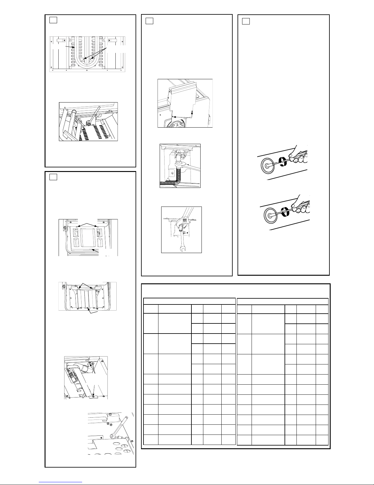
5
CHANGE GRIDDLE ORIFICE
(if present)
Locate the 3/4” long griddle orifice.
Select the proper orifice size for your gas
and burner from the conversion chart.
A. Lift off the griddle flue cover. Remove the 2
inside clamping screws.
B. Lift out the cast-
iron grease trough.
Slide the griddle
toward the rear
and out of the
hold-down tabs
along the bottom.
C. Carefully lift and
hold the griddle
while pulling
additional length
of the capillary
from the entry
hole. Stand the
griddle on end in the grease sump.
D. Remove the 2
hold-down screws
at the rear of the
burner.
Pull the burner
straight back
toward the rear
and out of the gas inlet.
E. Use a 1/2” deepwell
socket to remove
and replace the
orifice.
Reverse these steps
to reassemble the
griddle. Push excess
capillary back into the entry hole. Place the
unused orifice in the holder for possible
future use.
Griddle Flue Cover
Clamping Screws
Leveling Screws
NOTE: Remove
the 2 screws
positioned on
the inside only.
Do not remove
the outermost
screws—they
are for leveling.
Back of Range
6A
CHANGE MAIN BAKE BURNER
ORIFICE
Locate the 3/4” long bake burner orifice.
Select the proper orifice size for your gas and burner
from the conversion chart.
A. Remove the oven door and set aside in a
safe location.
B. Remove the 2 oven bottom hold-down
screws from the rear of the cover.
C. Slide the oven bottom forward and set
aside.
D. Remove the burner diffuser screw.
E. Lift the front of the burner diffuser up
slightly and slide it forward to disengage
the clips at the rear. Set the burner diffuser
aside.
Hold-Down Screws
Oven
Bottom
Diffuser screw
Clips
31-10766-1 11-10 GE
1
Front Access Cover
ZGP304 MAIN ORIFICES
A 84XL or 126HXN
orifice will be used
on these three
burners.
Use a 108XL or
190XN orifice
for the right
front burner.
Page 2
BURNER OUTPUT RATINGS: BTU/HR
7
CHANGE MAIN/COMPANION
BROIL BURNER ORIFICE
Locate the broil burner orifice.
Select the proper orifice size for your gas and
burner from the conversion chart.
The rear cover should still be removed from
converting the regulator(s). Refer to section 2 for details if it is not.
A. Remove the 2 broil duct cover retension
screw. Lift up and slide out to remove.
B. Loosen and remove the broil supply tube
nut from the broil orifice holder.
C.
Using an adjustable wrench and a 7/16” (11
mm) box end wrench to loosen and remove
and replace the broil orifice.
D. Reverse these steps to reassemble the
griddle.Push excess capillary back into the
entry hole.Place the unused orifice in the
holder for possible future use.
6A
CHANGE MAIN BAKE BURNER
ORIFICE (Cont.)
F. Remove the 2 burner retention screws.
G.
Lift the front of the burner up slightly and slide
forward setting aside (careful not to damage
the igniter.)
H. Use a 1/2” deepwell socket to remove and
replace the orifice.
I. Reverse these steps to reassemble the
griddle. Push excess capillary back into the
entry hole. Place the unused orifice in the
holder for possible future use.
Burner retention
screws
Burner
6B
CHANGE COMPANION BAKE
BURNER ORIFICE (if present)
Locate the 3/4” long bake burner orifice.
Select the proper orifice size for your gas and
burner from the conversion chart.
A. Remove the oven door and set aside in a
safe location.
B. Remove the 2 oven bottom hold-down
screws from the rear of the cover.
C. Slide the oven bottom forward and set
asside.
D. Remove the burner diffuser screw.
E. Lift the front of the burner diffuser up
slightly and slide it forward to disengage
the clips at the rear. Set the burner diffuser
aside.
F. Remove the 3 burner retension screws (1 in
front and 2 at the rear)
G. Lift the front of the burner up slightly and
slide leftward to remove.
H. Use a 1/2” deep-
well socket to
remove and replace the orifice.
I. Reverse these
steps to reassemble the
griddle.Push
excess capillary
back into the entry hole.Place the unused
orifice in the holder for possible future use.
Hold-Down
Screws
Oven
Bottom
Diffuser Screw
Clips
Burner
Retension
Screws
Remove
screws
8
ADJUST BURNER FLAMES
Normally, burners do not need further
adjustment. Make adjustments only when
necessary.
A. Turn on the gas. Plug in electrical cord.
B. Turn all burners on highest setting and
check the flames. They should be blue in
color. When using LP gas, the flames may
have some yellow tipping at the ends of the
flame. Foreign particles in the gas line may
cause an orange flame at first, but this will
soon disappear.
C. Turn the burner knob to “LO” while
observing the flame.
Adjust the setting of the upper row of flames
using the valve bypass screw as follows:
Adjustments must be made with two other
burners in operation on a medium setting.
This prevents the upper row of flames from
being set too low, resulting in the flame
being extinguished when other burners are
turned on.
D. To adjust the flame, remove the knobs. Insert
a small flat-blade screwdriver into the hole
in the center of the valve stem to engage
screw.
• If the flames are too small or flutter, turn the
screw counterclockwise.
• If the flames are too large, turn the screw
clockwise.
E. Make the adjustment by slowly turning the
screw until flame appearance is correct.
2
NG (Natural) Gas, 5” W.C.P.
MODEL BURNER
BTU
RATE
ORIFICE
SIZE
ID
ZGP48
ZGP36
ALL SURF. Main 16,800
0.075”
(1.90mm)
190XN
BURNERS Simmer 1,200
0.002”
(0.51mm)
51SL
ZGP304
RF BURNER
Main 16,800
0.075”
(1.90mm)
190XN
Simmer 1,200
0.002”
(0.51mm)
51SN
ZGP304
RR, LR, LF
Main
Simmer
8,800
0.050”
(1.26mm)
126HXN
1,200
0.002”
(0.51mm)
51SN
ALL GRILL 15,000
0.0689”
(1.75mm)
0.069
ALL GRIDDLE 18,000
0.076”
(1.93mm)
0.076
ZGP48/
ZGP36
BAKE MAIN 24,500
0.0886”
(2.25mm)
0.089
ZGP30 BAKE MAIN 23,500
0.0866”
(2.20mm)
0.087
ZGP48 BAKE COMPANION 10,500
0.0531”
(1.35mm)
0.053
ALL BROIL MAIN 12,500
0.063”
(1.60mm)
160
ZGP48 BROIL COMPANION 9,000
0.052”
(1.32mm)
132
LP (Propane) Gas, 10” W.C.P.
MODEL BURNER
BTU
RATE
ORIFICE
SIZE
ID
ZGP48
ZGP36
ALL SURF. Main 13,800
0.043”
(1.08mm)
108XL
BURNERS Simmer 1,200
0.013”
(0.34mm)
34SL
ZGP304
RF BURNER
Main 13,800
0.043”
(1.08mm)
108XL
Simmer 1,200
0.013”
(0.34mm)
34SL
ZGP304
RR, LR, LF
Main
Simmer
7,900
0.033”
(0.84mm)
84XL
1,200
0.013”
(0.34mm)
34SL
ALL GRILL 14,000
0.047”
(1.19mm)
0.047
ALL GRIDDLE 16,000
0.047”
(1.19mm)
0.047
ZGP48/
ZGP36
BAKE MAIN 23,000
0.055”
(1.397m)
0.055
ZGP30 BAKE MAIN 21,500
0.0531”
(1.35mm)
0.053
ZGP48 BAKE COMPANION 10,000
0.0374”
(0.95mm)
0.037
ALL BROIL MAIN 11,500
0.041”
(1.04mm)
104
ZGP48 BROIL COMPANION 9,000
0.0360”
(0.91mm)
91
Page 3

5
CHANGEZ L’ORIFICE DE LA
PLAQUE CHAUFFANTE (si installé)
Saisissez-vous de l’orifice de la plaque
chauffante de (19 mm) 3/4” longueur.
Sélectionnez le type de gaz.
LP
—
.047, NAT—.076
A.
Soulevez le couvercle d’aération de la plaque
chauffante. Retirez les 2 vis intérieures de fixation.
B.
Soulevez les
lèchefrites en fonte.
Faite glisser la
plaque chauffante
vers l’arrière et hors
des languettes de
maintien le long de
la partie inférieure.
C.
Soulevez
délicatement la
plaque chauffante
tout en la maintenant.
Tirez la longueur
excédentaire de tube
capillaire par le trou d’entrée. Posez la plaque
chauffante debout sur
la lèchefrite.
D. Retirez les 2 vis de
maintien à l’arrière
du brûleur.
Tirez le brûleur
directement vers
l’arrière et détachez-le de l’arrivée du gaz.
E. Utilisez une clé à
douille d’1/2 po pour
retirer et réinstaller
l’orifice.
Inversez la procédure
pour remonter la
plaque chauffante.
Repoussez la longueur excédentaire de tube
capillaire dans le trou d’entrée. Placez l’orifice
non utilisé sur le possible pour une possible
utilisation ultérieure.
Consignes
d’installation
Conversion du gaz naturel au propane
Conversion du propane au gaz naturel
AVERTISSEMENT : Cette
conversion doit être effectuée par un plombier ou
un fournisseur de gaz qualifié conformément aux
consignes du fabricant et aux réglementations et
aux normes en vigueur afin d’éviter toute blessure
ou dommage matériel. L’agence en charge de
l’installation assume la responsabilité de la
conversion.
AVERTISSEMENT : La table de
cuisson telle qu’elle est livrée depuis l’usine est
conçue pour être utilisée avec le gaz adéquat.
Si vous souhaitez l’utiliser avec un autre type de
gaz, vous devez d’abord remplacer les orifices et
convertir le régulateur de pression.
AVERTISSEMENT : Vous devez
procédez aux réglages suivants avant d’allumer le
brûleur afin d’éviter toute blessure grave. Assurezvous que le régulateur de pression ait été converti
comme indiqué lors de l’étape 2.
OUTILS DONT VOUS AUREZ BESOIN
POUR LA CONVERSION
Lunettes protectrices
Petit tournevis à tête plate
(pointe de 2 à 2,4 mm ou
3/32”, 60 mm de longueur)
Clé à molette
Tournevis à douille
7 mm et 1/4”
7/16” (11 mm)
Open End Wrench
Petites pinces
Clé à douille 1/2”
(12,7 mm)
Tournevis
cruciforme
1
SUPPORT D’ORIFICE
Le support d’orifice de la cuisinière est situé sur le
panneau d’accès frontal et au fond de la cuisinière.
Retirez les portes (voyez les instructions à la page
10) et les vis supérieures et inférieures du panneau
d’accès frontal. Retirez
le panneau frontal pour
accéder au support
d’orifice.
Des orifices additionnels
peuvent être présents.
Utilisez uniquement les
orifices mentionnés aux
instructions pour votre
cuisinière ou plaque de
cuisson.
2
CONVERTIR LE RÉGULATEUR
Débranchez l’électricité sur le disjoncteur
ou la boîte à fusible du circuit principal.
A. Coupez le gaz en fermant le robinet de
fermeture sur l’appareil ou le mur.
B. Déplacez la cuisinière de manière à pouvoir
accéder à l’arrière de l’appareil.
C.
Enlevez le panneau arrière pour pouvoir
accéder aux régulateurs - (1) sur les cuisinières
de 76 et 91 cm (30 et 36 po) et (2) cuisinières de
121 cm (48 po).
D.
Convertissez le régulateur de pression:
• Dévissez le bouchon avec la ventouse.
• Placez votre doigt contre la partie plate du piston
et appuyez pour sortir la ventouse du bouchon.
• Observez attentivement le piston pour repérer la
position NAT ou LP.
• Retournez le piston de sorte que le type de gaz
souhaité
apparaisse à
côté du bas.
• Replacez le
piston dans le
bouchon.
• Vissez le
bouchon sur le
régulateur.
E. Inversez ces étapes pour réassembler le
régulateur de pression.
DOWN
FOR OFF
NAT
LP
LP
NAT
LP
NAT
NAT
LP
Joint
Bouchon
Piston
Position LP
(propane)
Position NAT
(gaz naturel)
Régulateur de pression
3 CHANGEZ LES ORIFICES DU BRÛLEUR
CONSEIL D’INSTALLATION :
Commencez par retirer tous
Orifices, puis replacez-les. Vous
éviterez ainsi tout oubli.
A. Retirez les grilles du brûleur,
les chapeaux et les têtes.
B. Desserrez les orifices
du brûleur du haut à l’aide
d’un tournevis à douille 7 mm.
Utilisez de petites pinces
pour soulever les orifices
délicatement.
L’orifice principal est situé
assez bas au centre
du brûleur, tandis que
l’orifice de mijotage est placé plus haut dans le
centre du brûleur.
IMPORTANT : Veuillez trouver le numéro de
modèle ci-dessous. Lisez chacune des étiquettes
des orifices afin de les identifier et de les placer
dans les emplacements indiqués.
A.
Replacez les orifices non utilisés sur le support. Fixez
le support à nouveau et la fiche d’instruction avec la
vis dans le lieu de rangement d’origine.
B.
Replacez les têtes des brûleurs, les chapeaux
et les grilles supérieures. Sur les cuisinières, replacez
la plaque d’aération arrière.
Chapeau de brûleur
Tête de
brûleur
Allumeur
d’étincelles
Base du brûleur
Orifice
principal
Orifice de
mijotage
ORIFICES DE MIIJOTAGE ZGP304
Un orifice de type 34SL ou 51SN
sera utilisé sur tous les brûleurs.
ZGP364, ZGP366, ZGP484, ZGP486
ORIFICES DE
MIIJOTAGE
Un orifice de type
34SL ou 51SN sera
utilisé sur tous les
brûleurs.
Utilisez un orifice 108XL
ou 190XN pour le brûleur
situé devant à droite.
ORIFICES
PRINCIPAUX
4
CHANGEZ L
’ORIFICE DU
GRILL
(si installé)
Localisez l’orifice du grill d’une longueur
de 1–1/2” (4 cm).Sélectionnez le type
de gaz. LP
—
.047, NAT—.067
A. Retirez le couvercle du grill,
les grilles et le cadre. Enlevez
le déflecteur de rayonnement.
B. Retirez les 2 vis à tête
hexagonale du haut de
l’allumeur.
• Retirez 1 vis de
chagne côte du
dispositif de protection
du brûleur.
• Soulevez le dispositif
de protection.
C. Poussez avec
précaution sur
l’allumeur sur le côté et
sous le brûleur.
Ne tirez ou ne coincez
pas le câble.
Retirez les 4 vis de
fixation du brûleur, 2
à l’avant et 2 autres à
l’arrière. Faites glisser le
brûleur vers l’arrière et
à l’extérieur de l’arrivée
du gaz.
D. Utilisez une clé à
douille 1/2” pour retirer
et réinstaller l’orifice .
Inversez la procédure pour
remonter le grill. Assurezvous de placer l’orifice
non utilisé sur le support
pour pouvoir l’utiliser
ultérieurement.
Retirez
les deux
vis à tête
hexagonale
Vis du
dispositif de
protection
Boîtier du
brûleur
Allumeur
Brûleur
Partie avant de la cuisinière
Avant de la cuisinière
Couvercle d’aération de la plaque chauffante
Vis de maintien
Vis de mise de niveau
NOTE : Retirez
seulement les 2 vis de
fixation sur l’intérieur.
Ne retirez pas les vis les
plus à l’extérieur—elles
sont utilisées pour la
mise de niveau.
Arrière de la cuisinière
6A
REMPLACEMENT DU BRÛLEUR DE
CUISSON DU FOUR LATÉRAL (si présent)
Repérez l’orifice de 19 mm (3/4 po) de long du
brûleur de cuisson du four.
Choisissez la dimension d’orifice adéquate selon
votre type de gaz et de brûleur au diagramme de
conversion.
A. Retirez la porte du four et placez-la dans un
endroit sûr.
B. Retirez les deux fonds du four fixés à l’aide de vis
et situés à l’arrière du panneau.
C.
Glissez le fond du four vers l’avant puis déposez-le
tout près.
D.
Retirez les deux vis du diffuseur de brûleur.
E.
Soulevez légèrement la partie frontale du diffuseur du brûleur et glissez-le vers l’avant pour
déclencher les fixations arrière. Mettez le diffuseur de côté.
Hold-Down Screws
Oven
Bottom
Diffuser screw
Clips
31-10766-1 11-10 GE
1
Panneau d’accès frontal
Tube
capillaire
ORIFICES PRINCIPAUX ZGP304
Un orifice de
type 84XL ou
126HXN sera
utilisé sur ces
trois brûleurs.
Utilisez des
orifices 108XL ou
190XN sur tous
les brûleurs.
Page 4

PUISSANCES NOMINALES DE SORTIE DU BRÛLEUR : BTU/HR
7
REMPLACEMENT DE L’ORIFICE
DU BRÛLEUR DE CUISSON DU
FOUR LATÉRAL
Repérez l’orifice brûleur de cuisson du four.
Choisissez la dimension d’orifice adéquate
selon votre type de gaz et de brûleur au diagramme de conversion.
Le panneau arrière doit être retiré des régulateurs de conversion. Consultez l’article
2 pour obtenir tous les détails si celui-ci est
toujours en place.
A. Retirez les deux vis de retenue du cou-
vercle de conduit du gril
B. Retirez les deux vis de retenue du cou-
vercle de conduit du gril
C.
Utilisez une clé à ouverture variable et une
douille de 11 mm (7/16 po) pour dévisser,
retirer et replacer l’orifice du gril.
D. Inversez ces étapes pour rassembler la
plaque chauffante. Poussez l’excès du
tube capillaire dans l’orifice d’entrée.
Placez l’orifice inutilisé dans le support
pour une utilisation future..
6A
REMPLACEMENT DU BRÛLEUR DE
CUISSON DU FOUR LATÉRAL
(suite)
F.
Retirez les trois vis de retenue du brûleur (1 à
l’avant et deux à l’arrière).
G.
Soulevez légèrement la partie frontale du brûleur
et glissez-le vers la gauche pour le retirer.
H.
Utilisez une douille profonde de 12,7 mm (1/2
po) pour retirer et replacer l’orifice.
I.
Inversez ces étapes pour rassembler la plaque
chauffante. Poussez l’excès du tube capillaire
dans l’orifice d’entrée. Placez l’orifice inutilisé
dans le support pour une utilisation future.
Vis de retenue
du brûleur
Brûleur
6B
REMPLACEMENT DU BRÛLEUR DE
CUISSON DU FOUR LATÉRAL (si présent)
Repérez l’orifice de 19 mm (3/4 po) de long du
brûleur de cuisson du four.
Choisissez la dimension d’orifice adéquate selon
votre type de gaz et de brûleur au diagramme de
conversion.
.
A. Repérez l’orifice de 19 mm (3/4 po) de long
du brûleur de cuisson du four.
B.
Retirez la porte du four et placez-la dans un
endroit sûr.
C. Glissez le fond du four vers l’avant puis
déposez-le tout près..
D. Retirez les deux vis du diffuseur de brûleur.
E. Soulevez légèrement la partie frontale
du diffuseur du brûleur et glissez-le vers
l’avant pour déclencher les fixations arrière. Mettez le diffuseur de côté.
F. Retirez les trois vis de retenue du brûleur (1
à l’avant et deux à l’arrière).
G. Soulevez légèrement la partie frontale du
brûleur et glissez-le vers la gauche pour le
retirer.
H. Utilisez une
douille profonde
de 12,7 mm (1/2
po) pour retirer et
replacer l’orifice.
I.
Inversez ces
étapes pour rassembler la plaque
chauffante. Poussez l’excès du tube capillaire dans l’orifice
d’entrée. Placez l’orifice inutilisé dans le
support pour une utilisation future.
Vis serre-tôle
Fond du
four
Vis du diffuseur
Fixations
Vis de retenue
du brûleur
Retirez
les vis
8
AJUSTEZ LES FLAMMES DU
BRÛLEUR
Les brûleurs ne requièrent normalement aucun
ajustement. Ne procédez à des ajustements que
si cela s’avère nécessaire.
A. Allumez le gaz. Branchez le cordon
d’alimentation.
B. Allumez les brûleurs au maximum et vérifiez
les flammes. Elles devraient être bleues. Si
vous utilisez du propane, la pointe de flammes
devrait être jaune. La présence d’objets
étrangers dans le tuyau d’alimentation en
gaz devraient donner une couleur orange à
la flamme au début. L’orange disparaît par la
suite.
C. Tournez le bouton du brûleur sur “LO” (feu
doux) tout en observant la flamme.
Ajustez le réglage de la première rangée de
flammes avec la vis de dérivation de vanne de
la manière suivante :
Vous pouvez procédez à des ajustements sur
deux autres brûleurs en marche sur un réglage
moyen. La rangée supérieure des flammes est
ainsi réglée sur un niveau qui n’est pas trop
faible, ce qui pourrait provoquer l’extinction de la
flamme lorsque d’autres brûleurs sont allumés.
D. Pour ajuster la flamme, retirez les boutons.
Introduisez un tournevis à tête plate dans le
trou au centre du piston de la vanne pour
engager la vis.
• Si les flammes sont trop petites ou vacillent,
tournez la vis dans le sens inverse des aiguilles
d’une montre.
• Si les flammes sont trop grandes, tournez la vis
dans le sens des aiguilles d’une montre.
E. Procédez à l’ajustement en tournant
doucement la vis jusqu’à ce que l’aspect de la
flamme soit le bon.
2
Gaz naturel, avec P.C. de 12,7 cm (5 po)
MODÈLE
BRÛLEUR
PUIS-
SANCE
BTU
DIMENSION
ORIFICE
ID
ZGP48
ZGP36
BRÛLEURS Princ.
16,800
0,075”
(1,90mm)
190XN
TOUTES SURFACES
Mijoter
1,200
0.002”
(0,51mm)
51SL
ZGP304
BRÛLEUR AD
Princ.
16,800
0.075”
(1,90mm)
190XN
Mijoter
1,200
0.002”
(0,51mm)
51SN
ZGP304
AD, GD, AG
Princ.
Mijoter
8,800
0.050”
(1.,26mm)
126HXN
1,200
0.002”
(0,51mm)
51SN
ALL FOUR
15,000
0.0689”
(1,75mm)
0.069
ALL TABLE DE CUISSON
18,000
0.076”
(1,93mm)
0.076
ZGP48/
ZGP36
CUISSON - PRINCIPAL
24,500
0.0886”
(2,25mm)
0.089
ZGP30
CUISSON - PRINCIPAL
23,500
0.0866”
(2,20mm)
0.087
ZGP48
CUISSON - POUR LATÉRAL
10,500
0.0531”
(1,35mm)
0.053
ALL GRIL PRINCIPAL
12,500
0,063”
(1.60mm)
160
ZGP48
GRIL - FOUR LATÉRAL
9,000
0,052”
(1.32mm)
132
Gaz propane, avec P.C. de 25,5 cm (10 po)
MODÈLE
BRÛLEUR
PUIS-
SANCE
BTU
DIMENSION
ORIFICE
ID
ZGP48
ZGP36
BRÛLEURS Princ.
13,800
0.043”
(1,08mm)
108XL
TOUTES SURFACES
Mijoter
1,200
0.013”
(0,34mm)
34SL
ZGP304
BRÛLEUR AD
Princ.
13,800
0.043”
(1,08mm)
108XL
Mijoter
1,200
0.013”
(0,34mm)
34SL
ZGP304
AD, GD, AG
Princ.
Mijoter
7,900
0.033”
(0,84mm)
84XL
1,200
0.013”
(0,34mm)
34SL
ALL FOUR
14,000
0.047”
(1,19mm)
0.047
ALL TABLE DE CUISSON
16,000
0.047”
(1,19mm)
0.047
ZGP48/
ZGP36
CUISSON - PRINCIPAL
23,000
0.0551”
(1,397mm)
0.055
ZGP30
CUISSON - PRINCIPAL
21,500
0.0531”
(1,35mm)
0.053
ZGP48
CUISSON - POUR LATÉRAL
10,000
0.0374”
(0,95mm)
0.037
ALL GRIL PRINCIPAL
11,500
0.041”
(1,04mm)
104
ZGP48
GRIL - FOUR LATÉRAL
9,000
0.0360”
(0,91mm)
91
Page 5

5
CAMBIE EL ORIFICIO DE LA
PLANCHA
(si corresponde)
Ubique el orificio de la plancha de 3/4”
de longitud. Seleccione el tipo de gas.
LP—.047, NAT—.076
A. Levante la tapa de ventilación de
la plancha. Retire los 2 tornillos interiores de
apriete.
B. Retire la canaleta
para grasa de
hierro fundido.
Deslice la plancha
hacia atrás y fuera
de las lengüetas
de sujeción a lo
largo de la parte
inferior.
C. Con cuidado
levante y sostenga
la plancha mientras
agrega longitud
desde el capilar al orificio de entrada.
Sostenga la plancha en el extremo del cárter
para grasa.
D. Retire los 2 tornillos
de sujeción en la
parte trasera del
quemador.
Quite el quemador
empujando hacia
atrás y afuera de la entrada de gas.
E. Use la llave de cubo
larga de 1/2” para
retirar y reemplazar
el orificio.
Realice los pasos
hacia atrás para
volver a ensamblar
la plancha. Vuelva a colocar el capilar
excesivo nuevamente en el orificio de
entrada. Coloque el orificio no utilizado en el
soporte para posibles usos futuros.
Instrucciones
de instalación
Conversión de gas natural a gas LP
Conversión de gas LP a gas natural
ADVERTENCIA: Esta conversión
debe efectuarla un instalador calificado o un
proveedor de gas de acuerdo con las instrucciones
del fabricante y con todos los códigos y
requerimientos de la autoridad competente.
No seguir estas instrucciones puede provocar
lesiones graves o daños a la propiedad. La agencia
calificada a cargo de este trabajo asume la
responsabilidad de la conversión.
ADVERTENCIA: La estufa, como
se envía de fábrica, se encuentra configurada
para funcionar con una clase de gas determinada.
Si desea utilizar su estufa con otro gas, primero
deben reemplazar los orificios y convertir el
regulador de presión.
ADVERTENCIA: Los siguientes
ajustes deben realizarse antes de encender el
quemador. No hacerlo puede provocar una lesión
grave. Asegúrese de que el regulador de presión se
haya convertido como se describe en el Paso 2.
HERRAMIENTAS NECESARIAS PARA
LA CONVERSIÓN
1
SOPORTE DE ORIFICIOS
El retenedor del orificio de la estufa se encuentra
detrás del panel de acceso frontal en la base de la
estufa. Retire la(s) puerta(s) (Consulte las instrucciones
en la página 10) y los tornillos
en la parte superior e inferior
del panel de acceso frontal.
Retire el panel de acceso
frontal para lograr acceso al
retenedor del orificio.
Podría haber orificios
adicionales presentes.
Use únicamente los
orificios especificados en
las instrucciones para su
estufa u hornilla.
2
CONVIERTA EL REGULADOR
Desconecte el suministro de energía desde
el interruptor de circuitos o la caja de
fusibles.
A. Corte el suministro de gas cerrando la válvula
de apagado manual de la unidad o de la pared.
B. Mueva la estufa para lograr acceso a la parte
posterior de la unidad.
C. Retire la parte posterior de la estufa para
lograr acceso al regulador(es) - (1) en estufas
de 30” y 36” y (2) en estufas de 48”.
.
D.
Convierta el regulador de presión:
• Desenrosque la tapa del émbolo.
• Coloque el pulgar contra el lado plano del
émbolo y presione hacia abajo para remover el
émbolo de la tapa.
•
Mire bien el émbolo para ubicar la posición NAT o LP.
• Dé vuelta el émbolo para que el gas deseado se
vea cerca de la
parte inferior.
•
Vuelva a colocar
el émbolo en la
tapa.
• Enrosque la
tapa dentro del
regulador.
E. Reverse estos
pasos para volver a armar el regulador de
presión.
DOWN
FOR OFF
NAT
LP
LP
NAT
LP
NAT
NAT
LP
Junta
Tapa
Émbolo
Posición LP
Posición NAT.
Regulador de presión
3
CAMBIE LOS ORIFICIOS DE LOS
QUEMADORES
CONSEJO DE INSTALACIÓN:
Primero quite todos los orificios
y luego comience a colocarlos
de nuevo. Esto lo ayudará a
evitar la posibilidad de que
algunos no vuelvan a colocarse.
A. Quite las rejillas de los
quemadores, las tapas de los
quemadores y cabezales de
los quemadores.
B. Afloje los orificios del
quemador superior utilizando
una llave de tuercas de 7 mm.
Utilice alicates pequeños para
quitar los orificios con mucho
cuidado.
El orificio principal se encuentra en la parte inferior del
centro del quemador, mientras que el orificio de fuego
lento se encuentra más arriba al lado del centro del
quemador.
IMPORTANTE: Busque el número de modelo a
continuación. Lea cada etiqueta de los orificios para
identificarlos e instalarlos en las ubicaciones precisas
que se muestran.
A. Coloque los orificios sin usar de vuelta en el
soporte. Vuelva a instalar el soporte y la hoja
de instrucciones con el tornillo en la ubicación
de almacenamiento original.
B. Reemplace los cabezales, las tapas y las
rejillas superiores. En los modelos de cocina,
reemplace el reborde de ventilación trasero.
Tapa del quemador
Cabezal del
quemador
Encendedor
por chispa
Base del
quemador
Orificio
principal
Orificio
de fuego
lento
ZGP304 ORIFICIOS DE FUEGO LENTO
Un orificio 34SL o 51SN se utiliza
en todos los quemadores..
ZGP364, ZGP366, ZGP484, ZGP486
ORIFICIOS
DE FUEGO
LENTO
Un orificio 34SL
o 51SN se utiliza
en todos los
quemadores.
Utilice orificios 108XL
o 190XN en todos los
quemadores.
ORIFICIOS
PRINCIPALES
4
CAMBIE EL ORIFICIO DE LA
PARRILLA
(si corresponde)
Ubique el orificio de parrilla de 1–1/2” de
longitud. Seleccione el tipo de gas. LP—.047,
NAT
—
.067
A. Quite la tapa de la parrilla, las
rejillas y el armazón de la rejilla.
Levante el deflector radiante
hacia arriba y afuera.
B. Quite los 2 tornillos de cabeza
hexagonal de la parte superior
del encendedor.
• Saque un tornillo de
cada lado del marco
del quemador.
• Levante el marco.
C. Cuidadosamente,
empuje el encendedor
hacia un costado
debajo del quemador.
No hale del cable ni lo
pellizque.
Saque 4 tornillos de
sujeción del quemador,
2 en el frente y 2 en la
parte trasera. Deslice
la ensambladura del
quemador hacia atrás
y fuera de la entrada de
gas.
D. Utilice una llave
de cubo larga de
1/2” para sacar y
reemplazar el orificio. Invierta
estos pasos para volver a
montar la parrilla.
Asegúrese de colocar el
orificio sin usar en el soporte
para posibles usos futuros.
Quite los
2 tormillos
de cabeza
hexagonal
Tornillos del
marco
Marco del
quemador
Encendedor
Ensambladura
del quemador
Frente de la cocina
Frente de la cocina
Tapa de ventilación de la plancha
Tornillos de
apriete
Tornillos de
nivelación
NOTA: Retire
los 2 tornillos
posicionados sólo en
la parte interior. No
retire los tornillos más
alejados—cumplen la
función de nivelar.
Trasera de la cocina
6A
CAMBIE EL ORIFICIO DEL
QUEMADOR DE HORNEAR PRINCIPAL
Localice el orificio del quemador de hornear
de ¾” de largo.
Seleccione el tamaño de orificio correcto para su gas
y quemador en la tabla de conversión.
A.
Retire la puerta del horno y coloque a un
lado en un lugar seguro.
B.
Retire los dos tornillos de sostienen la base
del horno de la parte trasera de la cubierta.
C.
Glissez le fond du four vers l’avant puis déposez-le
tout près.
D.
Retirez les deux vis du diffuseur de brûleur.
E. Levante el frente del difusor del quemador
ligeramente y deslice hacia adelante para
liberar los ganchos en la parte posterior.
Coloque el difusor del quemador a un lado.
Tornillos retenedores
Base del
horno
31-10766-1 11-10 GE
1
Cubierta de acceso frontal
Tornillo del difusor
Ganchos
Capilar
Gafas de seguridad
Destornillador plano
pequeño (2 a 2.4 mm o
3/32” de tamaño de punta,
60 mm de largo)
Llave Crescent
Llave de tuercas
de 7 mm y 1/4”
Alicates
pequeños
Llave de cubo larga de 1/2”
Destornillador
de estrella
Tirón con final
abierto de 11mm
y 7/16”
ORIFICES PRINCIPAUX ZGP304
Un orifice de type
84XL ou 126HXN
sera utilisé sur ces
trois brûleurs.
Utilisez des
orifices 108XL ou
190XN sur tous
les brûleurs.
Page 6

CALIFICACIONES DE SALIDA DEL QUEMADOR: BTU/HR
7
CAMBIE EL ORIFICIO DEL
QUEMADOR ASADOR
PRINCIPAL/ACOMPAÑANTE
Localice el orificio del quemador asador.
Seleccione el tamaño correcto de orificio para
su gas y quemador en la tabla de conversión.
La cubierta posterior deberá continuar retirada de la conversión del regulador(es). Consulte
la sección 2 para los detalles si no es así.
A. Retire los dos tornillos de retención de la
cubierta del ducto del asador. Levante y
deslice para quitar.
B. Afloje y retire la tuerca del tubo de sumi-
nistro del asador que se encuentra en el
retenedor del orificio del asador.
C.
Use una llave ajustable y una llave estriada
de 7/16” (11 mm) para aflojar, quitar y reemplazar el orificio del asador.
D. Inversez ces étapes pour rassembler la
plaque chauffante. Poussez l’excès du
tube capillaire dans l’orifice d’entrée.
Placez l’orifice inutilisé dans le support
pour une utilisation future..
6A
CAMBIE EL ORIFICIO DEL
QUEMADOR DE HORNEAR
PRINCIPAL
(cont.)
F. Retire los dos tornillos de retención del
quemador.
G.
Levante el frente del quemador ligeramente y
deslice hacia adelante para ponerlo a un lado
(con cuidado de no dañar la ignición).
H. Use una llave de copa de 1/2” para retirar
y reemplazar el orificio.
I. Reverse estos pasos para re-ensamblar la
plancha. Empuje la capilaridad excesiva
de nuevo en el orificio de entrada. Coloque
el orificio no utilizado en el retenedor para
posible uso futuro.
Tornillos de
retención del
quemador
Quemador
6B
CAMBIE EL ORIFICIO DEL
QUEMADOR DE HORNEAR
ACOMPAÑANTE
(sI LO HAy)
Localice el orificio quemador de hornear de ¾”
de largo.
Seleccione el tamaño correcto de orificio para su
gas y quemador en la tabla de conversión.
A. Repérez l’orifice de 19 mm (3/4 po) de long
du brûleur de cuisson du four.
B.
Retirez la porte du four et placez-la dans un
endroit sûr.
C. Deslice la base del horno hacia el frente y
coloque a un lado.
D. Retire el tornillo del difusor del quemador.
E. Levante el frente del difusor del difusor del que-
mador ligeramente y deslice hacia adelante
para liberar los ganchos en la parte posterior.
Coloque el difusor del quemador a un lado.
F. Retire los tres tornillos de retención del
quemador (1 al frente y 2 atrás).
G. Levante el frente del quemador ligera-
mente y deslice hacia adelante para quitar.
H. Use una llave
de copa de 1/2”
para retirar y
reemplazar el
orificio.
I.
Reverse estos pasos para re-ensamblar la plancha.
Empuje la capilaridad excesiva de nuevo en el orificio de
entrada. Coloque el orificio no utilizado en el
retenedor para posible uso futuro.
Tornillos retenedores
Fond du
four
Tornillo del difusor
Ganchos
Tornillos de retención
del quemador
Retirez
les vis
8
AJUSTE LAS LLAMAS DEL
QUEMADOR
Normalmente, los quemadores no necesitan
nuevos ajustes. Realice los ajustes sólo cuando
sea necesario.
A. Encienda el gas. Enchufe el cable eléctrico.
B. Encienda todos los quemadores en la
configuración más alta y controle las
llamas. Tienen que ser de color azul.
Cuando utilice gas LP, las llamas pueden
tener puntas amarillas. Partículas extrañas
en la línea de gas pueden provocar una
llama anaranjada al comienzo, pero esto
desaparecerá rápidamente.
C. Gire la perilla del quemador de la estufa a
“LO” (bajo) mientras observa la llama.
Ajuste la configuración de la hilera
superior de las llamas utilizando el tornillo
de derivación de válvula de la siguiente
manera:
Los ajustes deben efectuarse con otros
dos quemadores que funcionen en una
configuración media. Este procedimiento
evita que la hilera superior de las llamas sea
demasiado baja, lo que provoca que la llama
se apague cuando los otros quemadores se
encienden.
D. Para ajustar la llama, quite las perillas.
Introduzca un destornillador pequeño
de lados planos a través del orificio en
el centro del vástago de la válvula para
enganchar el tornillo.
• Si las llamas son demasiado pequeñas o se
agitan, gire el tornillo en sentido contrario a
las agujas del reloj.
• Si las llamas son demasiado grandes, gire
el tornillo en sentido de las agujas del reloj.
E. Realice el ajuste girando el tornillo
lentamente hasta que la apariencia de la
llama sea la correcta.
2
Gas NG (Natural), 5” W.C.P.
MODELO
QUEMADOR
CALIFI-
CACIÓN
BTU
TAMAÑO
ORIFICIO
ID
ZGP48
ZGP36
Principal
QUEMADORES TODA
16,800
0.075”
(1.90mm)
190XN
SUPERFICIE
Fuego lento
1,200
0.002”
(0.51mm)
51SL
ZGP304
Principal
QUEMADOR RF
16,800
0.075”
(1.90mm)
190XN
Fuego lento
1,200
0.002”
(0.51mm)
51SN
ZGP304
Principal
RR, LR, LF
Fuego lento
8,800
0.050”
(1.26mm)
126HXN
1,200
0.002”
(0.51mm)
51SN
Todos PARILLA
15,000
0.0689”
(1.75mm)
0.069
Todos PLANCHA
18,000
0.076”
(1.93mm)
0.076
ZGP48/
ZGP36
HORNEAR PRINCIPAL
24,500
0.0886”
(2.25mm)
0.089
ZGP30
HORNEAR PRINCIPAL
23,500
0.0866”
(2.20mm)
0.087
ZGP48
HORNEAR
ACOMPAÑANTE
10,500
0.0531”
(1.35mm)
0.053
Todos ASAR PRINCIPAL
12,500
0.063”
(1.60mm)
160
ZGP48
ASAR ACOMPAÑANTE
9,000
0.052”
(1.32mm)
132
LP (Propane) Gas, 10” W.C.P.
MODELO
QUEMADOR
CALIFI-
CACIÓN
BTU
TAMAÑO
ORIFICIO
ID
ZGP48
ZGP36
Principal
QUEMADORES TODA
13,800
0.043”
(1.08mm)
108XL
SUPERFICIE
Fuego lento
1,200
0.013”
(0.34mm)
34SL
ZGP304
Principal
QUEMADOR RF
13,800
0.043”
(1.08mm)
108XL
Fuego lento
1,200
0.013”
(0.34mm)
34SL
ZGP304
Principal
RR, LR, LF
Fuego lento
7,900
0.033”
(0.84mm)
84XL
1,200
0.013”
(0.34mm)
34SL
ALL
PARILLA
14,000
0.047”
(1.19mm)
0.047
ALL
PLANCHA
16,000
0.047”
(1.19mm)
0.047
ZGP48/
ZGP36
HORNEAR PRINCIPAL
23,000
0.055”
(1.397mm)
0.055
ZGP30
HORNEAR PRINCIPAL
21,500
0.0531”
(1.35mm)
0.053
ZGP48
HORNEAR
ACOMPAÑANTE
10,000
0.0374”
(0.95mm)
0.037
ALL
ASAR PRINCIPAL
11,500
0.041”
(1.04mm)
104
ZGP48
ASAR ACOMPAÑANTE
9,000
0.0360”
(0.91mm)
91
 Loading...