

Page 1
Installation
Instructions
If you have questions, ca!180&GE-CARESorvisit ourwebsite at:w.monogram.com
Free-Standing Side-by-Side
Stainless Steel Refrigerator
ZFSB25DSS
ZFSB26DSS
Monogram:
Page 2
Safety Information
BEFORE YOU BEGIN
Read these instructions completely and carefully.
•IMPORTANT- S ,,etheseinstructions
fin" local inspector's use.
•IMPORTANT- Obse,,'e ,llg,,,'e,'ning
codes and ordinances.
• Note to Installer - Be sure to leave these
instructions with the Consumer.
• Note to Consumer - Kee I) these instructions with
w)ur Owner's Manual for fllture refl_rence.
WARNING:
This appliance must be properly grotmded. See
"(;rotmding the Refrigerator," page 4.
AVERTISSEMENT :
(Yet appareil doit &tre correctement mis _'_la terre.
Consulter <_MiNe _'lla terre du r0frig0rateur >, .pa_e_ 4.
If you received a damaged refri,*erator you should
immediately contact your dealer or builder.
Skill Level - Installation of this refl'igerator requires
basic mechanical, carl)entry and plmnbing skills. Proper
installation is the responsibility of the installer. Product
tailm'e due to improper installation is not covered
under the GE Appliance Warranty: See the Owner's
Manual tin" warranty information.
CAUTION:
Due to the weight and size of this refrigerator, and to
reduce the risk of personal injm'y or damage to the
product - T_O PEOPI,E ARE REQUIRED FOR
PROPER INSTAI,IATION.
PRUDENCE:
_ cause du poids et de la taille de ce r_frig&'atem" et
pore" r&luire le risque de blessm'e et de dommages,
li, ECUT DEUX PERSONNES POUP, EMRE
I,'INSTAI,IATION CORRECTEMENT.
WARNING:
• Use this appliance only fin" its intended pro'pose.
• hmnediately repair or replace electric service cords
that become fra)'ed or damaged.
• UnI)lug the reli'igerator before cleaning or making
repairs.
• Repairs should be made by a qualified service
technician.
AVERTISSEMENT :
• ll ne taut utiliser cet appareil que pore" l'utilisation
aI)I)ropri_e.
• R_parer ou remplacer imm(_diatement tout cordon
_lectrique efliloch_ ou endommag_.
• I1 taut d_brancher le r_frig_rateur avant le
nettoyage ou toute intervention.
• I,es r(_parations doivent &tre taites par tm
technicien qualifi_.
CONTENTS
Plamting Information
Product Dimensions and Clearances .............................. 3
The h_stallation Space ...................................................... 3
Installation Instructions
Tools, Hardware, Materials .............................................. 4
Grom_ding the Refrigerator . ........................................... 4
Step 1, Move Refl'igerator Indoors .................................. 5
Step 2, Install X_ater I,ine ................................................. 6
For Monogrmn local service in your area, call
1.800.444.1845.
For Monogrmn service in Canada, call
1.888.880.3030
For Monogram Parts mad Accessories, call
1.800.626.2002.
www. monogram.com
Step 2A, RO Water i,ine ................................................... 7
Step 3, Connect Water Supply ......................................... 7
Step 4, Connect Power. .................................................... 7
Step 5, Move Refrigerator Into Position ......................... 7
Step 6, i,evel Refl'igerator ................................................ 8
Step 7, i,evel Dom_ ........................................................... 8
Step 8, Start Icemaker. ..................................................... 9
Step 9, Temperature Controls ......................................... 9
Step 10, Install Toekick .................................................... 9
2
Page 3
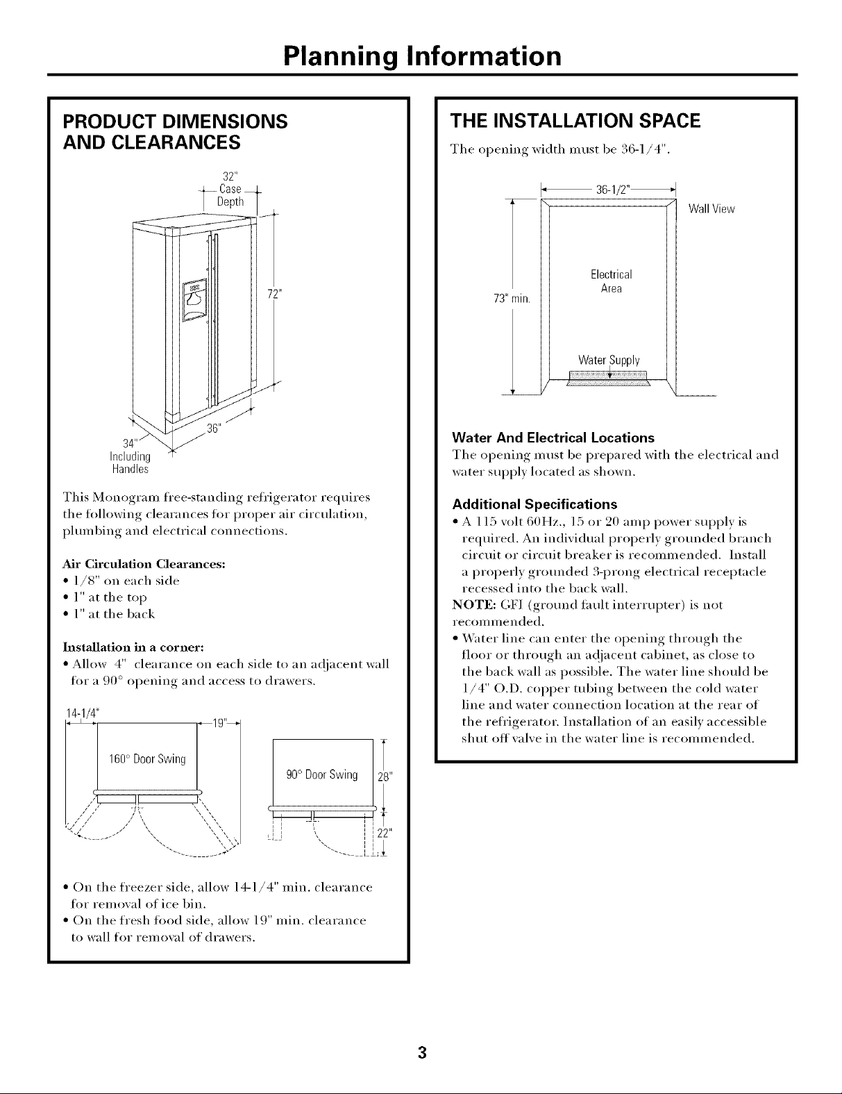
Planning Information
PRODUCT DIMENSIONS
AND CLEARANCES
32"
36 _'
34""
Including
Handles
This Monogran_ free-standing refrigerator requires
the fl)llowing clearances for i)roper air circulation
I_lmnbing, and electrical connections.
Air Circulation Clearm_ces:
• 1/8" on each side
• l" at the top
• 1" at the back
Installation in a corner:
• Allow 4" clearance on each side to an a(!iacent wall
for a . I ,90 ° o _ening and access to drawers.
14-1/4"
THE INSTALLATION SPACE
The opening width must be . o-//_ .
36-1/2"_
WallView
Electrical
73"rain.
Water And Electrical Locations
The opening must be prepared with the electrical and
water suppl)located as shown.
Additional Specifications
• A 115 volt 60Hz., 15 or 20 amp power supply is
required. An individual properly grotmded branch
circuit or circtfit breaker is recommended. Install
a properly grotmded 3-prong electrical receptacle
recessed into the back wall.
NOTE: OF] (grotmd thult interrupter) is not
recomi_lended.
• _,V_ter line can enter the opening through the
floor or through an a(!jacent cabinet, as close to
the back wall as possible. The water line should be
1/4" O.D. copper tubing between the cold water
line and water connection location at the rear of
the refl'igerator. ]nstallation of an easily accessible
shut offwdve in the water line is recommended.
Area
• _ 160° Door Swing _19"_
!! .r,,,
)
90° Door Swing
!! J!.
"-.. ........ X'-
• On the freezer side, allow 14-1/4" rain. clearance
fl)r removal of ice bin.
• On the fresh food side, allow 19" rain. clearance
to wall for rein owd of drawers.
. i
"--- [
3
Page 4
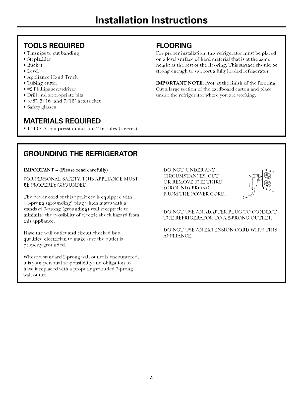
Installation Instructions
TOOLS REQUIRED
• Tinsnips to cut banding
• Stepladder
• Bucket
• I,evel
• Appliance Hand Truck
• Tubing cutter
• #9 Phillips screwdriver
• Drill and al)l)ropriate bits
• 3/8", 5/16" and 7/16" hex socket
• Safety glasses
MATERIALS REQUIRED
• 1/4 O.D. compression nut and 2 terrules (sleeves)
GROUNDING THE REFRIGERATOR
IMPORTANT - (Please read carefully)
FOR PERSONAl, SAFETY, THIS APPIJANCE MUST
BE PROPERI,Y GROUNDED.
The power cord of this appliance is equipped with
a 3-prong (grotmding) plug which mates with a
standard 3-prong (grounding) wall receptacle to
minimize the possibility of electric shock hazard from
this appliance.
Have the wall outlet and circuit checked by a
qualified electrician to make sure the outlet is
properly grotmded.
FLOORING
For proper installation, this refrigerator must be placed
on a level surfl_ce of hard material that is at the same
height as the rest of the flooring. This surface should be
strong enough to support a flflly loaded refl'igerator.
IMPORTANT NOTE: Protect the finish of the flooring.
Cut a large section of the cardboard carton and place
trader the refl'igerator where you are working.
DO NOT, UNDER ANY
CIR(XJMSTANCES, CUT
OR REMOVE THE THIRD
(GROUND) PRONG
FROM THE POWER CORD.
DO NOT USE AN ADAPTER PI,UG TO CONNECT
THE REFRIGERATOR TO A 2-PRONG OUTI,ET.
DO NOT USE AN EXTENSION CORD WITH THIS
APPI,IANCE.
Where a standard 2-prong wall outlet is encountered,
it is yore" personal responsibility and obligation to
have it replaced with a properly grotmded 3-prong
wall outlet.
4
Page 5

Installation Instructions
[STEP 1 ]MOVE REFRIGERATOR
INDOORS
IMPORTANT:
the installation location require a 36" rain. oi)ening., If
the opening is less than 36", the top cap and doors must
be i'ei//o_ ed.
NOTE: Skip this step if door remoxal is not required.
See instHlctions on next page, "To Mo_e The
Refrigerator Indoors."
NOTE: To prevent damage, leave inside
packaging, door spacer and outside
protective wrap in place until the refit is
moved to the installation location.
REMOVE THE DOORS
The top cap must be removed to access hinges. It is best
to I'eIl/OVe one door at a time.
A. Remove 2 screws and springs on top of the
refrigerator; one on each side. Push the top cap
forward and litt up fl'om the rear.
B. Remove 2 screws holding the top filler strip, lilt off.
C. Open both doors. Renlove the 2 toekick screws and
pull fi)rward to I'elllOVe.
D. Disconnect the water line coupler by pushing against
the collar on the leti side. Disconnect wire harness.
E. Remove 2 screws holding top hinge to the case.
Careflfll> lilt off door.
Follow the same procedure to remove the fresh food
door.
A
Wire Harness Water Line Coupler
/
5
Page 6

Installation Instructions
[STEP 1] (continued)
To move the refrigerator indoors:
• Place a piece of the carton or soft cloth against the
side panel of the refl'igerator to pad and protect the
stainless steel finish.
• Place the refl'igerator on the handtruck with a side
against the truck mtiy.
• Move the refrigerator indoors.
lSTEP2] INSTALL WATER LINE
• A cold water supply is required fl)r automatic
icemaker operation. The water pressure must be
between 40 and 120 p.s.i.
• Route ]/4" OD COl)per tubing between house cold
water line and the water connection location.
• Measure the distance fl'om the water wflve on the
back of the refl'igerator to the water supply line.
Add 8 flint length to allow the refl'igerator to be
moved away fl'om the wall atier installation. Bend
the tubing into 3 coils of about 10".
REINSTALL DOORS
Refer to the illustration on page 5.
• Carefully, route the water line tubing and electrical
through the fl'eezer side bottom hinge. I.ower the
door onto bottom hinge.
• Sec/IYe top hinge.
• Insert the tubing all the way into the couple_:
• Reconnect the wiring harness.
• Replace top filler strip.
• Replace top cap with original screws and springs.
HINT: Use tape or Perma Gum to prevent the spring
fl'om sliding off the screw.
Folh)w the sanle procedure to reinstall the fl'esh tood door
CompressionNut
Saddle Type
Shuto_.ve
Packing_
Outlet Valve
NOTE: The only GE approved plastic tubing is
supplied in GE SmartCmmect'" Refrigerator Tubing
kits. Do not use any other plastic water supply line
because the line is under pressure at all times. Certain
types of plastic will crack or rupture with age and
cause water damage to your home.
GE Smart(:onnec( _Refrigerator Tubing Kits are
awdlable in the fi)llowing lengths:
2' (.6 m) - _\_X08X10002
6' (1.8 m) - WX08X10006
15' (4.6 m) - WX08X10015
25' (7.6 m) - WX08X10025
Shut off the main water supply,
Turn on the nearest taucet long enough to clear the
line of water.
• Install a shut-off valve between the icelnaker water
valve and cold water pipe in a basement or cabinet.
The shut-off valve should be located where it will be
easily accessible.
NOTE: It is best to install the wflve into a vertical water
pipe. If wm install the wflve into a horizontal water
pipe, make the connection at the top or side, to avoid
drawing off anv sediment from the water pipe.
(Sleeve)
• Drill a 1/4" hole in the water pipe.
• Fasten the shut-offvalve to the pipe with pipe clamp.
• Tighten the clamp screws tmtil the sealing washer
begins to swell. Do not over tighten.
• Place a compression nut and terlule (sleeve) onto the
end of the tubing and connect it to the shut-off wflve.
Make sure the tubing is fitly inserted into the wflve
and ferrule is tightened.
• Turn on the main water supply and flush debris. Run
about a quart of water through the tubing into a
bucket. Shut off water supply at the shut-off wflve.
NOTE: Saddle type shut-off \:fives are included in many
water supply kits. Before i)urchasing, make sure a saddle
type wflve complies with your local i)lmnbing codes.
NOTE: Commonwealth of Massachusetts Plmnbing
Codes 248CMR shall be adhered to. Saddle wflves are
illegal and use is not permitted in Massachusetts.
Consult with wmr licensed i)lmnber.
6
Page 7

Installation Instructions
IStep2AI
WATER LINE
INSTALLATION WITH
A REVERSE OSMOSIS
SYSTEM
Skip this step when not using RO System
IMPORTANT:
When connecting to a (;E reverse osmosis water system
to your refi'igeratm; the GE RVKit must be used. For
other reverse osmosis water systems, tollow the
IIl_l n tl[;I ct tl I'e I"S recoil/ill enda tions.
If the water supply to the refrigerator is fl'om a Reverse
Osmosis Water System, use the retiigerator's filter
bypass i)lug. Using the refrigerator's water filtration
cartridge with the RO filter can result in hollow ice
cubes and slower water flow ti'om the water dispenser.
/
Turnleft to remove
Turn right to install bypassplug
]STEP 3 ]CONNECT WATER SUPPLY
Check to be sure that retrigerator power cord is not
plugged into the wall outlet.
1/4"Tubing
1/4"
CompressionNut
(sleeve)
Refrigerator
If you are using copper tubing:
• Place compression nut and ti_rmle (sleeve) onto
the end of the tubing coming from the house
water supply.
• Insert the end of the COl)per tubing into the
refrigerator connection at the back of the
refrigerator, as tar as possible. Hold the tubing
in place and tighten the fitting.
If you are using GE SmartConnect'" tubing:
• Insert the molded end of the tubing into the
refrigerator connection, at the back of the
refrigerator, and tighten the compression nut
tmtil it is hand tight.
• Then tighten one additional turn with a wrench.
Overtightening may cause leaks.
• Fasten the tubing into the clamp provided to hold
it in position. You may need to pry open the clamp.
• Ttu'n on the water at the shut-off wdve to check
tot leaks.
SmartConnectTM Tubing
]STEP 4 ]CONNECT POWER
• Connect refl'igerator power cord plug to a properly
gr(mnded receptacle.
• Check to make sure power to refrigerator is on by
opening reti'igerator door to see if interior lights
aI'e on.
[STEP 5] MOVE REFRIGERATOR
INTO POSITION
• Remove outside protectixe wrapping.
• Moxe the refrigerator into final installation position.
• Remoxe door spacer and all inside l)a('kaging, , .
Page 8

Installation Instructions
[STEP 6] LEVEL THE REFRIGERATOR
The refi'igerator can be leveled by a_!iusting the rollers
located near the 1)otmm hinges.
_ Raise
Rollers
Rollers have three purposes:
• The rollers a(!just so that the door closes easily
when opened about halfway. (Raise the fl'ont about
5/8" [l 6 ram] fl'om the floor.)
• Rollers a(!just so allow the refrigerator to be firmly
positioned on the floor and to prevent rocking
when the doors are opened and closed.
• The rollers allow you to move the refl'igerator fl'om
the wall for cleaning.
[STEP 7] LEVEL THE DOORS
If the doot_ are not evenly aligned at the top, the
refl'igerator door C}lilbe a(!justed.
• Use a 7/16" hex socket or wrench to [ili'n the door
a(!justing screw. Turn the screw to the right to raise
the (loot; tm'n leit to lower the door.
Align at Top
To Adjust the Rollers:
Roller Adjusting Screw
• Use a 3/8" hex socket or wrench to turn the
a_!justment screws. Turn the screws clockwise to
raise the refl'igerator, turn counterclockwise to
lower it.
NOTE: A nylon plug is imbedded in the threads of
the pin. The plug is designed to prevent the pin ti'om
turning. A wrench nlust be used to turn the pin.
• Tm'n the wrench one or two times. Open and close
the refl'igerator door to check alignment with the
freezer door at the top. A(!i ust again if necessary.
8
Page 9

Installation Instructions
[STEP 8] START ICEMAKER
• Flip the switch to l (ON) position. The icemaker
will not begin to operate until it reaches its
operating temperature of 15°F (-9°C)or below.
It will then begin operation automaticallv. It will
take 2-3 days to fill the ice bin.
• Be sure nothing interteres with the sweep of the
fl_eler arm. Do not place objects in the path of the
feeler arm.
• Discard the first flfll bucket of ice cubes.
• To turn the icemaker off, set the switch to O (OFF).
ISTEP91TEMPERATURE
CONTROLS
• The temperature controls are preset at 37 ° fi)r the
refl'igerator and 0°F for the freezer.
• Allow 24 hours to stabilize befln'e making
a_!justments.
ISTEP101INSTALL TOEKICK
• Press toekick into position and reinstall one screw
on each side.
ToekickScrew
IMPORTANT: The xented toekick must remain
unobstH/cted fin" proper air circulation.
9
Page 10

Notes
10
Page 11

Notes
11
Page 12

NOTE:While performing installations described in this book,
safety glasses or goggles should be worn.
For Mo_w_r_mz °°Io_d wn&:_, i_t your _m'a, call
1.800. 444. l ,_,'45.
NOTE: t roducl impvovemem is a continuing endeaxor
at G,en,::ral Ek_tric. Ther< fore, materials, appearanc_
_/ll(] s[)ecif]calions are sul._ject to ch_lllg(_ wilhot/I ll()titTe.
Pub.No.49-60160-4 ]
Dwg.No.197D4577PO01
10-04JR
Printedinthe UnitedStates
1
Monogram:
GEConsumer & Industrial
LouisvilJe, KY40225
@2004GE Company
 Loading...