

Page 1
GE Monogram ®
Installation
Instructions
36" Digital
Radiant Cooktop
Model
ZEU3G5ABG
ZE U3GWMRABG
Page 2
Before you begin--Read these instructions completely and carefully.
IMPORTANT: Save these instructions for local inspector's use.
IMPORTANT: OBSERVE ALL GOVERNING CODES AND ORDINANCES.
NOTE TO INSTALLER: Be sure to leave these instructions with the
Consu lneI'.
NOTE TO CONSUMER: Keep these instructions with your Use and Care
Book for future reference.
I_ This appliance must he properly grounded. See "Electrical Supply", page 4. I
If you have questions concerning the
installation of this product, call the GE
Answer Center :'_Consumer Information
Service at 800.626.2000, 24 hours a day,
7 days a week.
If you received a damaged cooktop, you
should contact your dealer.
CAUTION:
• This cooktop should be installed by a
qualified installer or service technician.
• Do not store items of interest to
children in cabinets above the
cooktop. They could be seriously
burned climbing on the cooktop to
reach them.
• Never use your cooktop for warming or
heating the room. Prolonged use of the
cooktop without adequate ventilation
can be hazardous.
• The cooktop should be easy to reach
and lighted by natural light during the
day.
Proper installation is the responsibility of the
installer. Product failure due to imf)roper
installation is not covered under the GE
Appliance Warranty. See the Use & Care
Guide for warranty information.
For Monogram local service in your area,
1-800-444-1845.
For Monogram Service in Canada
1-888-880-3030.
For Monogram Parts and Accessories, call
1-800-626-2002.
• Always disconnect the electrical service to
the unit before repairing or servicing the
cooktop. Disconnect the fuse or circuit
breaker. Failure to do so could result in a
dangerous or fatal shock. Know where your
main disconnect switch is located.
Check local building codes for the proper
method of cooktop installation. Local codes
vary. Installation, electrical connections and
grounding nmst comply with applicable
codes. In the absence of local codes, the
cooktop should be installed in accordance
with National Electrical Code ANSI/NFPA
70-1990.
Contents Design Information
Models Available ................................................................................................................................. 3
Dimensions and Clearances .............................................................................................................. 3
Advance Planning .............................................................................................................................. 3
Installation Preparation
Tools & Materials Required ............................................................................................................... 4
Electrical Location ............................................................................................................................. 4
Base Cabinet Heat Clearances .......................................................................................................... 4
Step 1: Cut the Opening .................................................................................................................... 5
Installation
Step 2: Install Cooktop ...................................................................................................................... 6
Step 3: Install Hold-down Brackets ................................................................................................... 6
Step 4: Connect Electrical ................................................................................................................. 7
Page 3
Design Information
Digital Radiant Cooktop
Models
Available
Dimensions
& Clearances
ZEU365ABG
DigitalRadiant Cooktop
ZEU3611VMRABG
DigitalRadiantCooktop with
warming burner
2" Min.
RightorLeft
SideWall
36"
/1 ....... #
34 3/8"
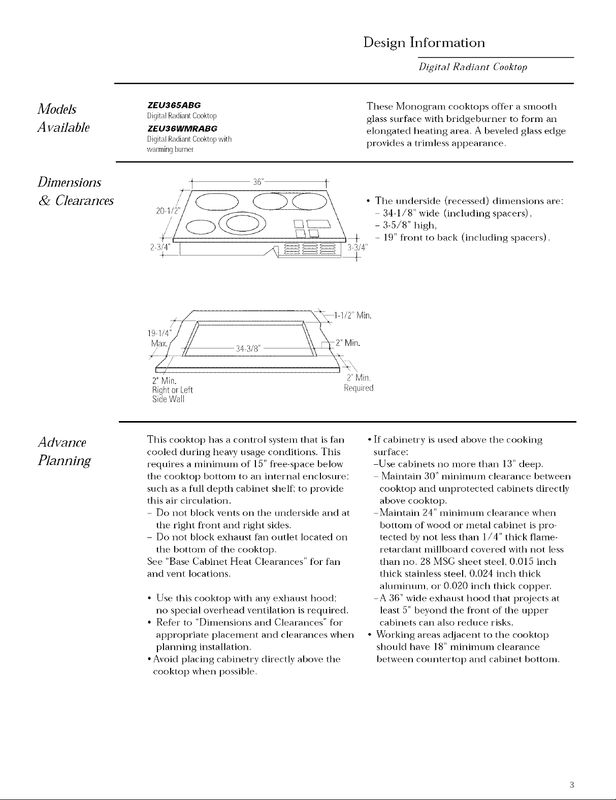
These Monogram cooktops offer a smooth
glass surface with bridgeburner to form an
elongated heating area. A beveled glass edge
provides a trimless appearance.
• The underside (recessed) dimensions are:
34-1/8" wide (including spacers),
- 3-5/8" high,
- 19" fi'ont to back (including spacers).
i 33/4"
2" Min,
Required
Advance
Planning
This cooktop has a control system that is fan
cooled during heavy usage conditions. This
requires a minimum of 15" fl'ee-space below
the cooktop bottom to an internal enclosure;
such as a full depth cabinet shelf; to provide
this air circulation.
- Do not block vents on the underside and at
the right fl'ont and right sides.
Do not block exhaust fan outlet located on
the bottom of the cooktop.
See "Base Cabinet Heat Clearances" for fan
and vent locations.
• Use this cooktop with any exhaust hood;
no special overhead ventilation is required.
• Refer to "Dimensions and Clearances" for
appropriate placement and clearances when
planning installation.
• Avoid placing cabinetry directly above the
cooktop when possible.
• If cabinetry is used above the cooking
surface:
Use cabinets no more than 13" deep.
Maintain 30" minimum clearance between
cooktop and unprotected cabinets directly
above cooktop.
-Maintain 24" minimum clearance when
bottom of wood or metal cabinet is pro-
tected by not less than 1/4" thick flame-
retardant millboard covered with not less
than no. 28 MSG sheet steel, 0.015 inch
thick stainless steel, 0.024 inch thick
aluminum, or 0.020 inch thick copper.
-A 36" wide exhaust hood that projects at
least 5" beyond the front of the upper
cabinets can also reduce risks.
• Working areas adjacent to the cooktop
should have 18" minimtHn clearance
between countertop and cabinet bottom.
Page 4

Installation Preparation
Di81tal Radiant Cooktop
Tools &
Materials
Required
Electrical
Location
• Drill and appropriate bits
• Electricor handdrill
• Pencil
• Ruler
• Carpenterssquare
• Handor saber saw
Warning, for
Personal Safety:
Remove house
fuse or open
circuit breaker
before beginning installa-
tion
• Flat-bladescrewdriver
• Wire strippers
• 120/240 volt or 120/208 voltjunction box
• Electrical cable, 3-conductoror 4conductorwire, as required
by local codes
Note: Donotuseanextension
cordwith this appliance
Do not use an extension
cord or adapter plug with
this appliance. Follow
National electrical codes
or prevailing local codes
and ordinances.
This cooktop operates on 240 or 208 volts,
60 Hz, power supply and requires an indi-
vidual, properly-grounded branch circuit,
protected by 40 amp fuse or circuit breaker.
Install the junction box within reach of the
power cable:
On the rear wall of the cabinet opening.
- At least 16" below the countertop.
16" Min
i
i
i
i
Junction Box
Location
• Connect house wiring to junction box in
accordance with local codes.
• Power is located on the bottom at the
center rear.
Warning: The improt)er connec-
tion of the equipment-grounding
conductor can result in a risk of
electric shock. Check with a
qualified electrician or service
representative if you are in doubt whether
the appliance is properly grounded.
b
Base
Cabinet
Heat
Clearances
IMPORTANT:
Control Housing Air Flow Provision
The control system is fan cooled during usage.
Installation into a cabinet must not block the
cooling air flow. Review illustrations carefully
before cutting the countertop to insure that
adequate space for the cooktop and clearances
for air space is available.
• Standoffs are positioned along the sides of
the cooktop. These standoffs provide a 1/4"
air gap between the countertop/cabinet and
the cooktop chassis.
DO NOT ATTEMPT TO REMOVE THE
STANDOFFS.
Outlet
Air intake
• Maintain 15"rain. clearance below cooktop
bottom to any horizontal surface such as a
full depth cabinet shelf.
Air intake
Page 5

SteI1
lq/2" Min,
Caution: Wall coverings,
countertopsandcabinetsshould
withstand200':Theat generated
bythe cooktop,
Installation Preparation
Di81tal Radiant Cooktop
18"Min.
i
I
Exhaust
Hood
2"Min
:43/8" Max. RightorLeft
/
\
\
\ 2" Min.
*A 30inches minimum clearance betweenthe top of the cookingsurface and the bottom of
an unprotected wood or metal cabinetor A 24 inchesminimum when bottom of wood or
metal cabinet is protected by not lessthan 1/4 inchthick fiame-retardant millboard covered
with not less than no,28 MSG sheet steel, 0,015 inch thick stainless steel, 0.024 inch thick
aluminum, or 0,020 inch thick copper,
SideWall
We recommend that this cooktop be installed
in 42" or larger base cabinets. If the cooktop is
installed into a 36" cabinet base, modifications
may be required. A 36" cabinet base must
allow for installation of hold-down clips and
air gaps at the sides. The side walls may need
to be cut away to provide this space.
• Countertop cutout for this cooktop must be:
34-3/8" wide.
- 19-1/4" deep.
• Allow clearances:
- 1-1/2" rain. between rear of cutout and
rear backsplash or wall.
2" nan. from cutout to fl'ont edge of
countertop.
- 2" nan. fl'om cutout to left and right side
adjacent walls.
• Install the junction box within reach of the
power cable, at least 16" below the
countertop.
• This cooktop is designed to hang fl'om the
countertop fl'om its fl'ont, back and side
flanges.
• Use a level to insure that countertop is level
and flat. If the countertop bows more than
1/16", additional cooktop support will be
required.
• For additional cooktop support, add braces
to the inside of the opening whenever
possible. Braces can be added along the rear
and on the sides of the opening. Be sure
that bracing does not block air flow to vents.
• This cooktop requires an additional 15" fl'ee
space below the cooktop bottom to full-
depth horizontal shelves for unrestricted air
flow to the control housing.
lllote: Somecountertopsmadefromsolidsurfacematerials,suchas
Corian_mayrequirespecialcutoutpreparation(suchasradius
corners).Alwaysconsultthecountertopmanufacturerforspecific
instructions,
Measure carefully using a carpenter's square
before cutting the countertop.
• Draw a centerline and measure 17-3/16" to
each side. Make sure sides of the opening
are parallel.
• Cut along the lines to complete the entire
cutout. Check again to be sure surface is
flat. Install supports if necessary.
Page 6

Install
Reflective
TapeWithin
1/2" of
Cutout
Installation
Digital Radiant Cooktop
Cooktop
Install
Hold-down
Brackets
TapeTopand _ .......ji
VerticalSides
• Smooth rough edges of tile cutout. Install
reflective tape (supplied) to the opening,
along the inside and 3/8" to 1/2" of the
opening edge.
ThumbScrew
Gasket
FromEdge
• Foam gasket (supplied) is on tile underside
of the cooktop flange all the way around,
approximately 1/8" fl'om cooktop flange
edge.
• Lower the cooktop into the countertop
opening.
• Make sure the cooktop is evenly seated and
supported.
Countertop_J_-
Standoff
CooktopBottom
I
Countertop
lnstall
aWood
BlockFor
Fragile
Countertop
Materials
• 2 hold-down clips and screws are supplied.
Use both clips to secure the cooktop to the
countertop.
• Thread screw into clip as shown.
• Insert clip into the upper or lower slot in
the cooktop side, depending upon
countertop thickness.
Secure clips on left and right sides or
fl'ont and back sides.
Hand tighten screws against countertop.
Over tightening may cause stress
and could cause the glass top to break.
If countertop material is fragile, use a wood
block between countertop and screw.
Page 7

Installation
Digital RacHant Cooktop
Connect
Electrical
,I CaaductarBranchCircut
Branch Circuit Cooktop
+120VAC Red (_j__ Red
Black Black
Bareor
GND
Verify that power is turned off at the source
Green Green
Neutral --
(White or Gray)
Not Used
Connect cooktop flexible power cable to
junction box:
• Use a proper-sized flexible conduit
connector, securely attached.
• Do not shorten power cable; it should
hang in a natural loop when installed.
When connecting to a 4-conductor branch
circuit:
• Connect red lead to branch circuit
red lead.
• Connect cooktop black lead to branch
circuit black lead.
• Connect cooktop ground conductor
(green) to branch circuit ground
conductor (bare or green).
3 Carductor BranchCircuil
BranchCircnit
+12or AC Red
White or
Neutral Bray
-120VAC
Black Black
Cooktop
Red
Green
When connecting to a 3-conductor branch
circuit:
• Connect cooktop red lead to branch circuit
red lead.
• Connect cooktop black lead to branch
circuit black lead.
• Connect cooktop bare copper or green
conductor to branch circuit ground lead
(white or gray).
If house wiring is not 2-wire with a
ground wire, a ground must be
provided by the installer.
When house wiring is aluminum,
be sure to use U.L. approved
anti-oxidant comt)ound and ahHninum-to-
copper connectors.
Page 8

Monogram '
General Electric OJmpany
Louisdlle, KY 40225
NOTE: While performinginstalhtions described inthB book,
satetyglassesor gogglesshouldbe worn
To obt+tin specific infofmation concemh+g aoy
JYlunogram product o1"service, call GE Ansi_er ('enter _
consumer h_fofnmtion service at 800.GgG.2000 ally
time, clqy o1"night.
For Molwgram local service in yoln" area, call
1 800 444 1845.
NO'TE: Product in_provement is a contintUng endeavor at General
Electric¸ ] hereR)re, materials, appearance and specifications are
sttl:_iecl to change withou_ notice¸
PId_ No 49 89/}0
Dwg No 164D3333P134
c: 1998 GE Appliances
(ND 963) 7/98
A 974 0218 000
 Loading...