

Page 1
Built-In Wall Oven
27" (68.6 cm) models
JKS10, JKP30, JKP35, JKP55, JKP70, JKP75,
PK916, PK956, ZEK938, ZEK958
Ilnstallat!on
nstruct=ons
If you have questions, call 1.800.GE.CARES or visit our website at:
ge.com
30" (76.2 cm) models
JTP30, JTP35, JTP55, JTP70, JTP75, PT916,
PT920, PT956, PT960, ZET938, ZET958
Before You Begin
Read these instructions carefully and completely.
• IMPORTANT-save these
instructions for local inspector's use.
• IMPORTANT-observe all
governing codes and ordinances.
• Note to Installer--Be sure to leave these
instructions with the consumer.
• Note to Consumer--Keep these
instructions for future reference.
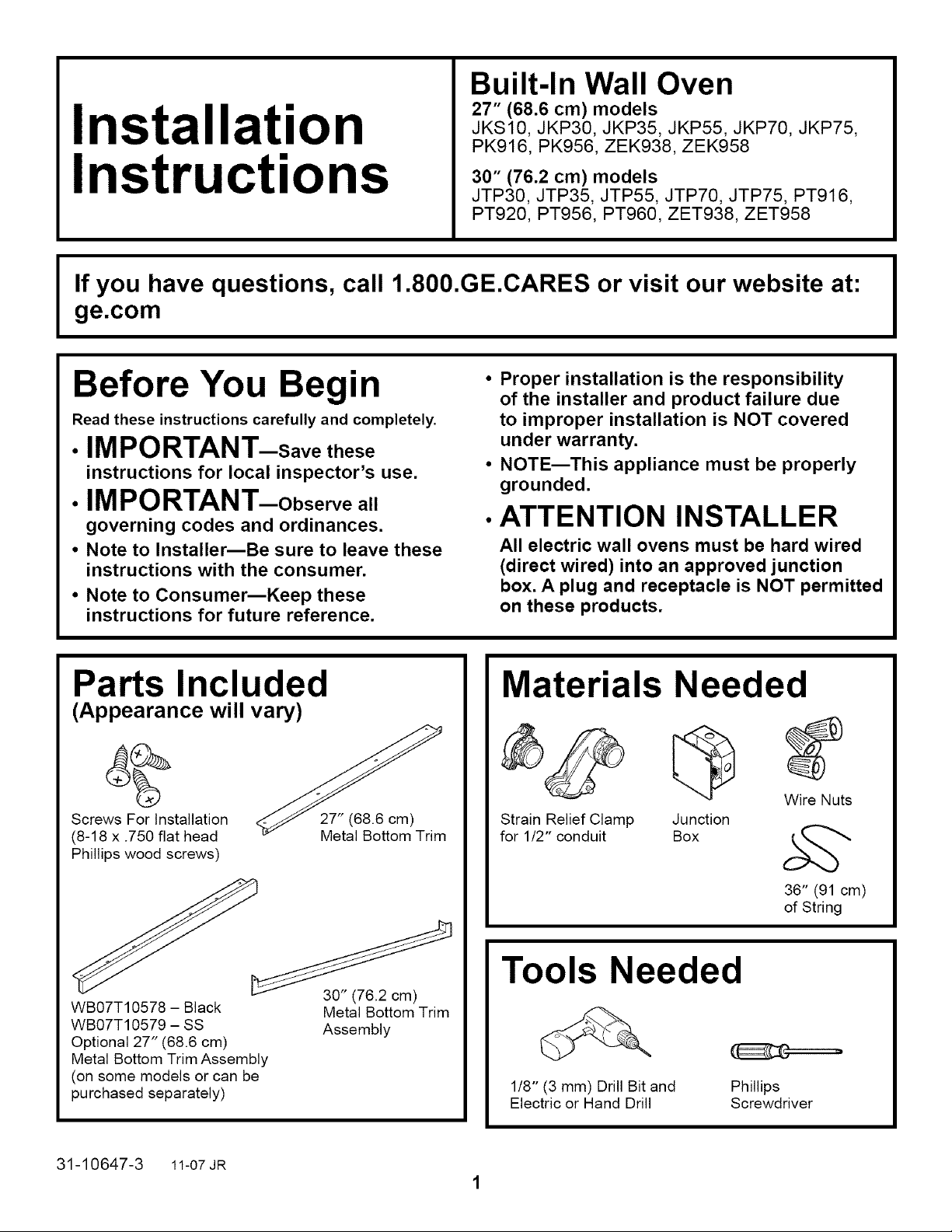
Parts Included
(Appearance will vary)
Screws For Installation
(8-18 x .750 flat head
Phillips wood screws)
27" (68.6 cm)
Metal Bottom Trim
• Proper installation is the responsibility
of the installer and product failure due
to improper installation is NOT covered
under warranty.
• NOTE--This appliance must be properly
grounded.
•ATTENTION INSTALLER
All electric wall ovens must be hard wired
(direct wired) into an approved junction
box. A plug and receptacle is NOT permitted
on these products.
Materials Needed
Wire Nuts
Strain Relief Clamp Junction
for 1/2" conduit Box
WB07T10578 - Black
WB07T10579 - SS
Optional 27" (68.6 cm)
Metal Bottom Trim Assembly
(on some models or can be
purchased separately)
31-10647-3 11-07JR
30" (76.2 cm)
Metal Bottom Trim
Assembly
Tools Needed
1/8" (3 mm) Drill Bit and
Electric or Hand Drill
36" (91 cm)
of String
Phillips
Screwdriver
Page 2
Installation instructions
PORTANT SAFETY I ST CTIONS
For Your Safety
• Be sure your oven is installed properly by
a qualified installer or service technician.
• Be sure the oven is securely installed in a
cabinet that is firmly attached to the house
structure. Weight on the oven door could
cause the oven to tip and result in injury.
Never allow anyone to climb, sit, stand or
hang on the oven door.
• Make sure the cabinets and wall
coverings around the oven can withstand
the temperatures (up to 200°F [93.3°C])
generated by the oven.
WARNING: The electrical
power to the oven supply line
must be shut off while line
connections are being made. Failure
to do so could result in serious injury
or death.
lectrical
Requirements
This appliance must be supplied with the proper
voltage and frequency, and connected to an
individual, properly grounded branch circuit,
protected by a circuit breaker or fuse. See the
rating plate located on the oven frame to determine
the rating of the product. Use the chart below to
determine the minimum recommended dedicated
circuit protection.
Recommended
KW Rating KW Rating Circuit Size
240V 208V (Dedicated)
<4.8 KW <4.1 KW 20Amp
4.9 KW-7.2 KW 4.3 KW-6.2 KW 30 Amp
7.3 KW-9.6 KW 6.3 KW-8.3 KW 40 Amp
9.7 KW-12.0 KW 8.4 KW-10.4 KW 50 Amp
lectrical
Requirements cont.
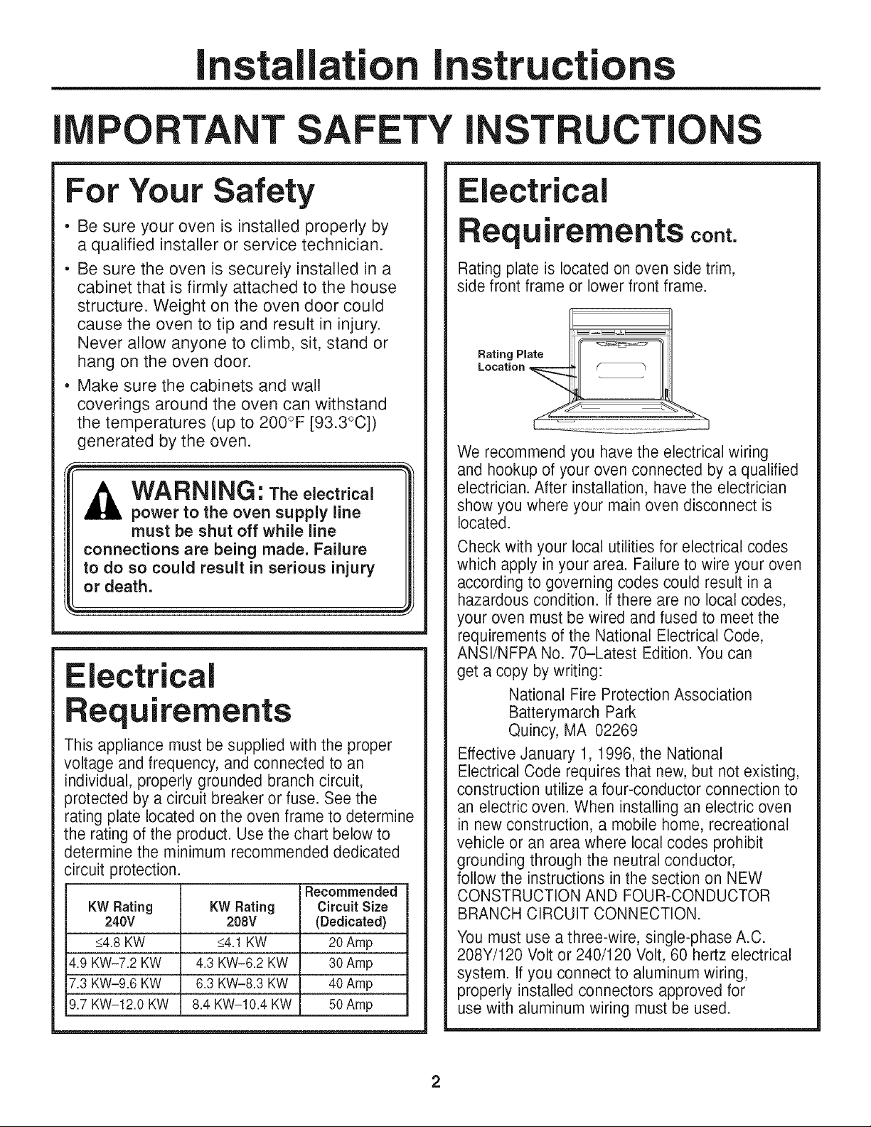
Rating plate is located on oven side trim,
side front frame or lower front frame.
Rating Plate
Location
We recommend you have the electrical wiring
and hookup of your oven connected by a qualified
electrician. After installation, have the electrician
show you where your main oven disconnect is
located.
Check with your local utilities for electrical codes
which apply in your area. Failure to wire your oven
according to governing codes could result in a
hazardous condition. If there are no local codes,
your oven must be wired and fused to meet the
requirements of the National Electrical Code,
ANSI/NFPA No. 70-Latest Edition. You can
get a copy by writing:
National Fire Protection Association
Batterymarch Park
Quincy, MA 02269
Effective January 1, 1996, the National
Electrical Code requires that new, but not existing,
construction utilize a four-conductor connection to
an electric oven. When installing an electric oven
in new construction, a mobile home, recreational
vehicle or an area where local codes prohibit
grounding through the neutral conductor,
follow the instructions in the section on NEW
CONSTRUCTION AND FOUR-CONDUCTOR
BRANCH CIRCUIT CONNECTION.
You must use a three-wire, single-phase A.C.
208Y/120 Volt or 240/120 Volt, 60 hertz electrical
system. If you connect to aluminum wiring,
properly installed connectors approved for
use with aluminum wiring must be used.
2
Page 3
Insta ion instructions
Pre-lnstallation
ALL INSTALLATION INFORMATION
ON THE FOLLOWING PAGES IS TO
BF USED FOR SINGLE AND DOUBLE
OVEN INSTALLATION!
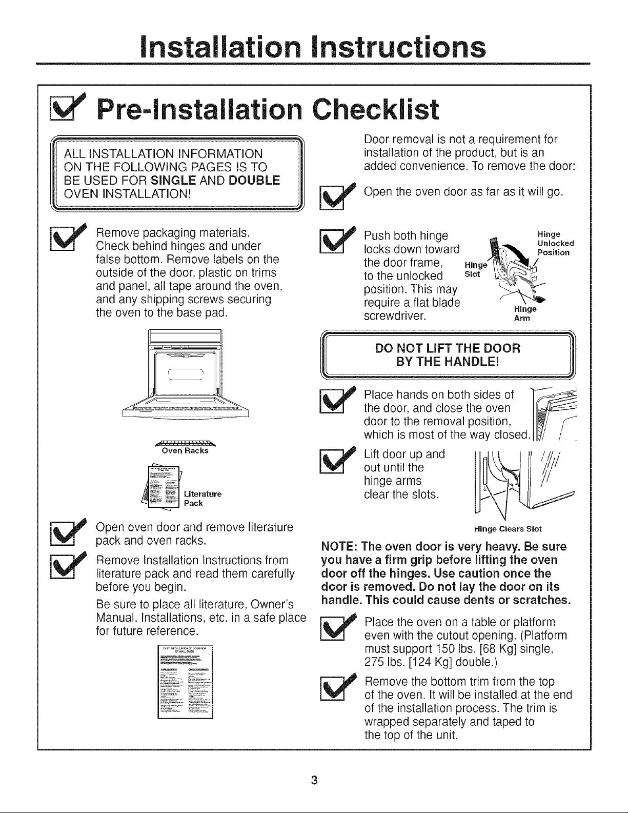
Remove packaging materials.
Check behind hinges and under
false bottom. Remove labels on the
outside of the door, plastic on trims
and panel, all tape around the oven,
and any shipping screws securing
the oven to the base pad.
__ =
Oven Racks
_ iterature
Pack
Chec ist
Door removal is not a requirement for
installation of the product, but is an
added convenience. To remove the door:
[_ Open the oven door as far as it will go.
Push both hinge Hinge
locks down toward ,_I_:'_L Position
the door frame, Hinge"I_
to the unlocked s_ot_.d
position. This may
require a flat blade
screwdriver. Arm
[_ DO NOT LIFT THE DOOR
[_ Place hands on both sides of "_
[_ ift door up and
the door, and close the oven 11_
door to the removal position, t_/
which is most of the way closed, t_'/
out until the
hinge arms
clear the slots.
_ :,,_ Unlocked
Hinge
Open oven door and remove literature
pack and oven racks.
Remove Installation Instructions from
literature pack and read them carefully
before you begin.
Be sure to place all literature, Owner's
Manual, Installations, etc. in a safe place
for future reference.
Hinge Clears Slot
NOTE: The oven door is very heavy. Be sure
you have a firm grip before lifting the oven
door off the hinges, Use caution once the
door is removed. Do not lay the door on its
handle. This could cause dents or scratches.
Place the oven on a table or platform
even with the cutout opening. (Platform
must support 150 Ibs. [68 Kg] single,
275 Ibs. [124 Kg] double.)
Remove the bottom trim from the top
of the oven. It will be installed at the end
of the installation process. The trim is
wrapped separately and taped to
the top of the unit.
3
Page 4
Installation instructions
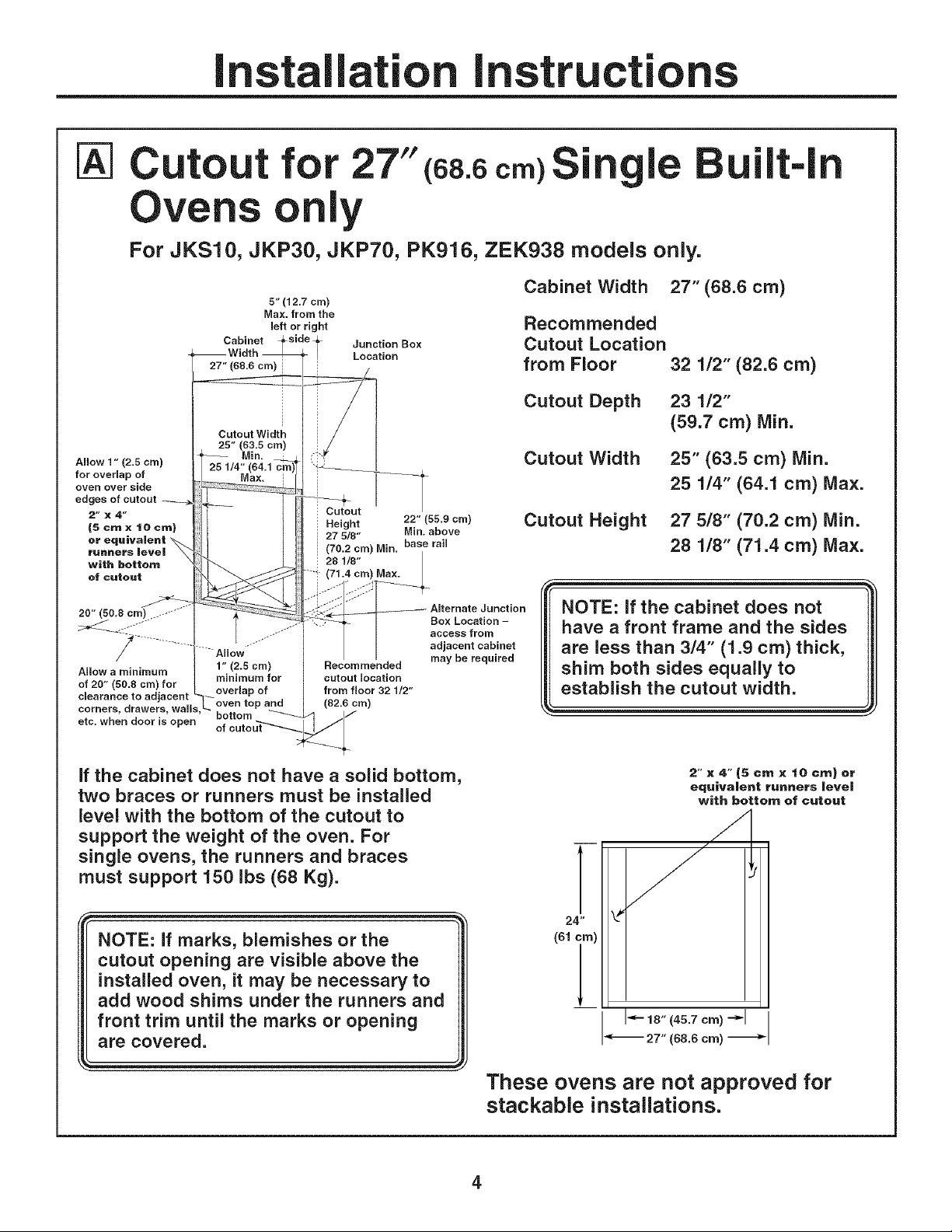
Cutout for 27" (68.6c )Single
Ovens on y
For JKS10, JKP30, JKP70, PK916, ZEK938 models only.
Max. from the
Cabinet_ _sk !_ Junction Box
27" (68.6 cm) i
Cutout Width /_
25" (63.5 cm)
Allow 1" (2.8 era)
for overlap of
oven over side
edges of cutout
2" x 4"
(Scmx tOcm)
0¥
runners level
with bottom
of cutout
20" (50.8 era)
Allow a minimum
ciearance°f20" (50.8teCta),41 _for overlap of
corners, drawers, wails, bottom
etc. when door is open of cutout'_"'_--_
a_jacen, oven top and
Min. j ,,: ,,
25 114" (64.1 "!-'
Max.
" Allow"
1" (2.5 cm)
minimum for
5" (12.7 cm)
left or right
I
/ Location
Cutout
Height 22" (55.9 cm)
27 5/8" Min. above
(70.2 cm) Min. base rail
28 118" I
access from
Box Location -
adjacent cabinet
Recommended may be required
cutout location
from Roor 32 1/2"
(82.6 cm)
uilt-ln
Cabinet Width
Recommended
Cutout Location
from Floor
Cutout Depth
Cutout Width
Cutout Height
NOTE: if the cabinet does not
have a front frame and the sides
are less than 3/4" (1.9 cm) thick,
shim both sides equally to
establish the cutout width.
27" (68.8 cm)
32 1/2" (82.6 cm)
23 1/2"
(59.7 cm) Min.
25" (63.5 cm) Min.
25 1/4" (64.1 cm) Max.
27 5/8" (70.2 cm) Min.
28 1/8" (71.4 cm) Max.
If the cabinet does not have a solid bottom,
two braces or runners must be installed
level with the bottom of the cutout to
support the weight of the oven. For
single ovens, the runners and braces
must support 150 Ibs (68 Kg).
NOTE: If marks, blemishes or the
cutout opening are visible above the
installed oven, it may be necessary to
add wood shims under the runners and
front trim until the marks or opening
are covered,
2" x 4" (5 cmx tO cm) or
equivalent runners love|
with bottom of cutout
T
24"
(61cm)
1
I-'_- 18" (45.7 cm) "-_1
"_ 27" (68,6 cm) "_
These ovens are not approved for
stackable installations.
4
Page 5
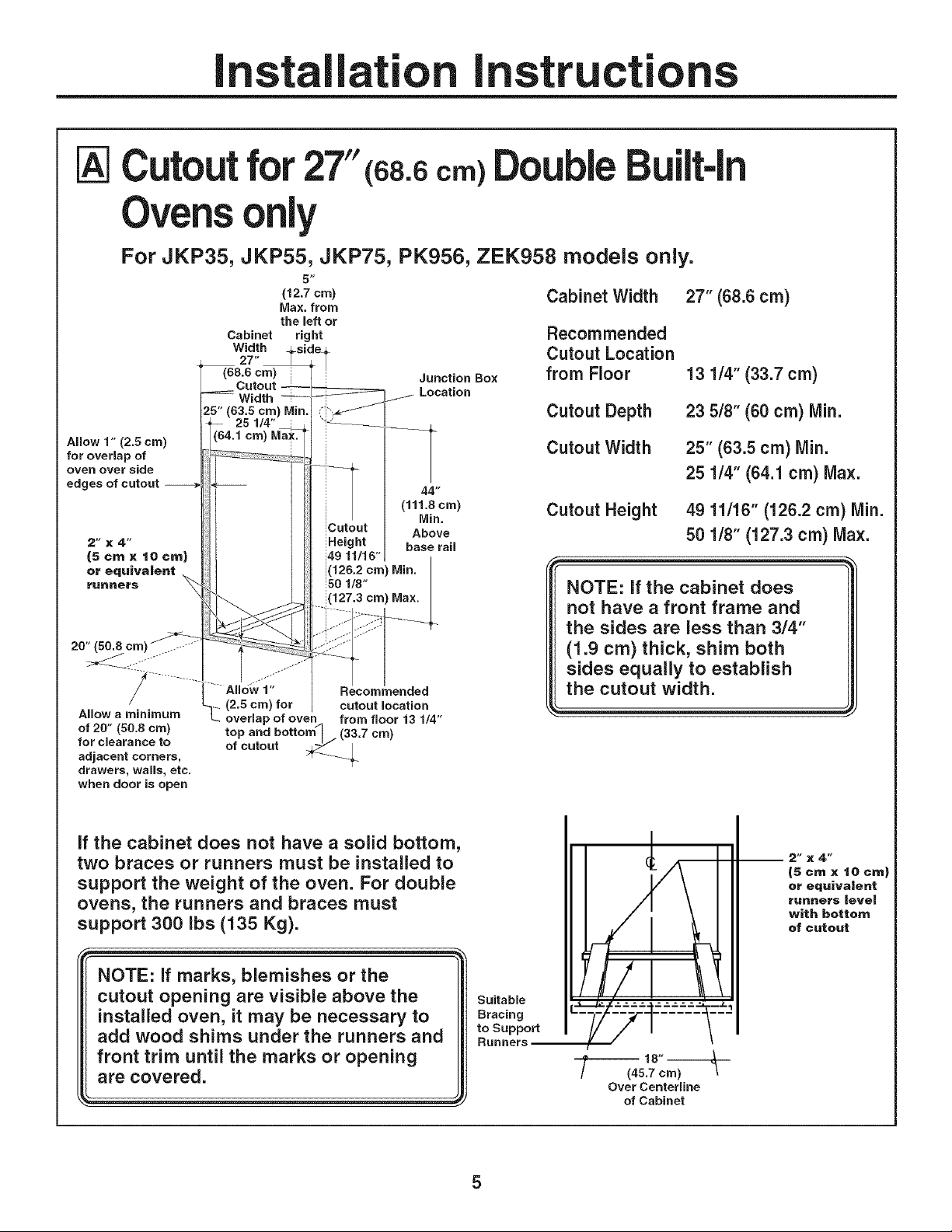
Cutoutfor 27"(68.6
Ovensonly
For JKP35, JKP55, JKP75, PK956, ZEK958 models only.
Allow 1" (2.5 cm)
for overlap of
oven over side
edges of cutout
20" (50.8
--_ j°s-
Allow a minimum
of 20" (50.8 cm)
for clearance to
adjacent corners,
drawers, walls, etc.
when door is open
Installation instructions
5"
(12.7 cm)
Max. from
the left or
Cabinet right
(68.6 cm) _
Cutout
5" (63.5 cm) Min.
25 1/4" i
i Junction Box
__ Location
(s4.1cm)M_,
icut°ut Above
iHeight base rail
i49 11116"
i(126.2 cm) IVlin.
150118"
i(127.3 cm) Max.
.... Ailo_vI"
(2,5 cm) for
overlap of oven from floor 13 114"
top and bottom_ (33.7 cm)
of cutout
Recommended
cutout location
(111.8 cm)
Min.
Cabinet Width
27" (68.6 cm)
Recommended
Cutout Location
from Floor
Cutout Depth
Cutout Width
13 1/4" (33.7 cm)
23 5/8" (60 cm) Min.
25" (63.5 cm) Min.
25 114" (64.1 cm) Max.
Cutout Height
49 11116" (126.2 cm) Min.
50 1/8" (127.3 cm) Max.
NOTE: If the cabinet does
not have a front frame and
the sides are less than 314"
(1.9 cm) thick, shim both
sides equally to establish
the cutout width.
if the cabinet does not have a solid bottom,
two braces or runners must be installed to
support the weight of the oven. For double
ovens, the runners and braces must
support 300 Ibs (135 Kg).
NOTE: If marks, blemishes or the
cutout opening are visible above the
installed oven, it may be necessary to
add wood shims under the runners and
front trim until the marks or opening
are covered.
-- 2" x 4"
(ScmxtOcm)
or equiva|ent
ruuners level
with bottom
of cutout
Suitable
Bracing
to Support
Runners
Over Centerline
of Cabinet
5
Page 6
Installation instructions
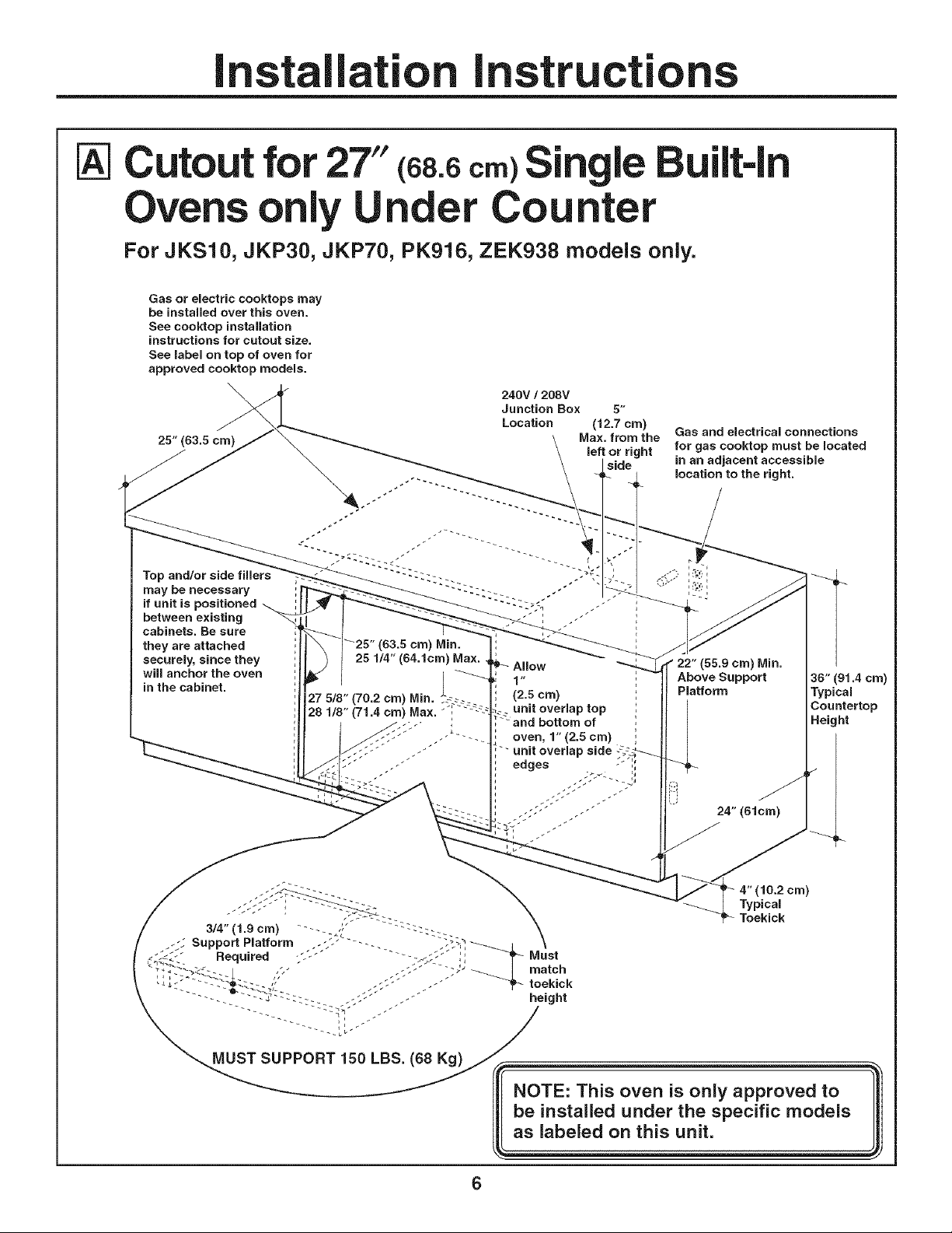
Cutout for 27" (68.6c_)Single Built-in
Ovens only Under Counter
For JKS10, JKP30, JKPT0, PK916, ZEK938 models only.
Gas or electric cooktops may
be installed over this oven.
See cooktop installation
instructions for cutout size.
See label on top of oven for
approved cooktop models.
\
25" (63.5 cm)
240V / 208V
Junction Box 5"
Location (12.7 cm)
Max. from the
left or right
side
Gas and electrical connections
for gas cooktop must be located
in an adjacent accessible
location to the right.
Top and/or side fillers
may be necessary
if unit is positioned
between existing
cabinets. Be sure
they are attached
securely, since they
will anchor the oven
in the cabinet.
_25" (63.5 cm) Min.
25 1/4" (64.1cm) Max.
27 5/8" (70.2 cm) Min.
28 1/8" (71.4 cm) Max.
_J J
Allow
I"
(2.5 cm)
unit overlap top _,
bottom of
oven, 1" (2.5 cm)
unit overlap side
edges
22" (55.9 cm) Min.
Above Support
Platform
4"(10.2 cm)
Typical
Toekick
36" (91.4 cm)
Typical
Countertop
Height
MUST SUPPORT 150 LBS. (68 Kg)
be installed under the specific models I_t
i NOTE: This oven is only approved to I_t
JJJ
6
Page 7
Cabinetry
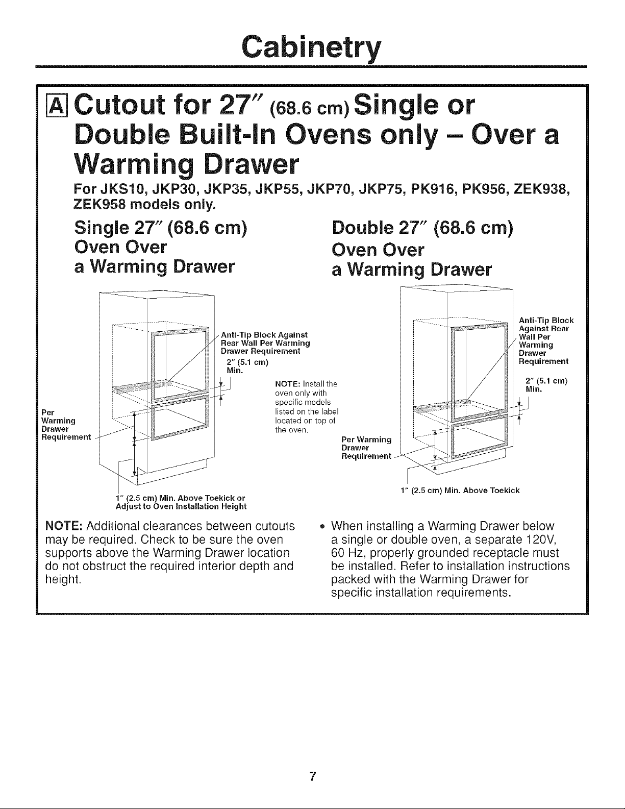
for 27" (68.6c_)Single or
uilt-ln Ovens only- Over a
Drawer
For JKS10, JKP30, JKP35, JKP55, JKPT0, JKP75, PK916, PK956, ZEK938,
ZEK958 models only.
Single 27" (68.6 cm)
Oven Over
a Warming Drawer
Anti-Tip Block Against
Rear Wall Per Warming
Drawer Requirement
2" (5.1 cm)
Min.
Per
Warming
Drawer
Requirement J
1" (2.5 cm) Min. Above Toekick or
Adjust to Oven Installation Height
NOTE: Additional clearances between cutouts
may be required. Check to be sure the oven
supports above the Warming Drawer location
do not obstruct the required interior depth and
height.
NOTE: Install the
oven only with
specific models
listed on the label
located on top of
the oven.
Double 27" (68.6 cm)
Oven Over
a Warming Drawer
Anti-Tip Block
Against Rear
• Wall Per
Warming
Drawer
Requirement
2" (5.1 era)
Min,
Per Warming
Drawer
Req=
1" (2.5 cm) Min. Above Toekick
When installing a Warming Drawer below
a single or double oven, a separate 120V,
60 Hz, properly grounded receptacle must
be installed. Refer to installation instructions
packed with the Warming Drawer for
specific installation requirements.
7
Page 8
Cabinetry
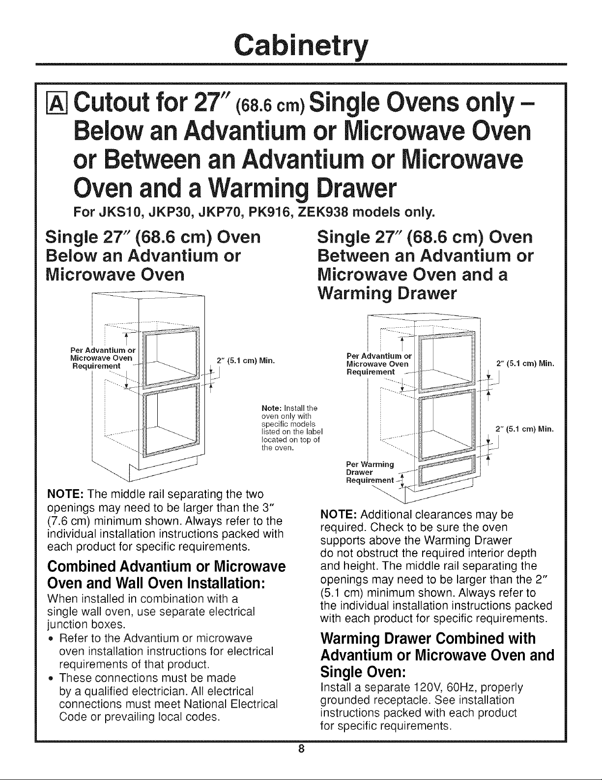
Cutoutfor 27"(68.6o_)SingleOvensonly-
BelowanAdvantiumor ;rowave Oven
or BetweenanAdvantiumor crowave
OvenandaWarmingDrawer
For JKS10, JKP30, JKP70, PK91& ZEK938 models only.
Single 27" (68.6 cm) Oven
Below an Advantium or
Microwave Oven
Per Advantium or
Microwave Oven
Requirement
NOTE: The middle rail separating the two
openings may need to be larger than the 3"
(7.6 cm) minimum shown. Always refer to the
individual installation instructions packed with
each product for specific requirements.
Combined Advantium or Microwave
Oven and Wall Oven Installation:
When installed in combination with a
single wall oven, use separate electrical
junction boxes.
Refer to the Advantium or microwave
oven installation instructions for electrical
requirements of that product.
These connections must be made
by a qualified electrician. All electrical
connections must meet National Electrical
Code or prevailing local codes.
2" (5.1 cm) Min.
Note: Install the
oven only with
specific models
listed on the label
located on top of
the oven.
Single 27" (68.6 cm) Oven
Between an Advantium or
Microwave Oven and a
Warming Drawer
Per Advautium or
Microwave Oven
Requirement
Per Warming
Drawer
Req
NOTE: Additional clearances may be
required. Check to be sure the oven
supports above the Warming Drawer
do not obstruct the required interior depth
and height. The middle rail separating the
openings may need to be larger than the 2"
(5.1 cm) minimum shown. Always refer to
the individual installation instructions packed
with each product for specific requirements.
WarmingDrawerCombinedwith
Advantiumor MicrowaveOvenand
SingleOven:
Install a separate 120V, 60Hz, properly
grounded receptacle. See installation
instructions packed with each product
for specific requirements.
2" (5.1 cm) Min.
2" (5.1 cm) Min.
8
Page 9
Installation instructions
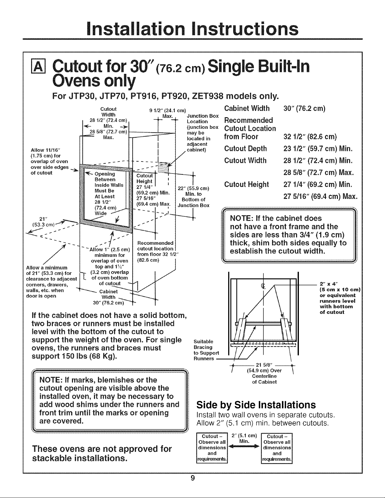
Cutoutfor 30"(76.2c )Sing Built-in
Ovensonly
For JTP30, JTP70, PT916, PT920, ZET938 models only.
Allow 11/16"
(1.75 cm) for
overlap of oven
over side edges
of cutout
21 "
(53.3 cm)I'Y_'_ -
Allow a minimum
of 21" (53.3 cm) for
clearance to adjacent
corners, drawers,
walls, etc. when
door is open
Cutout
Width
28 1/2" (72.4 cm)
5/8"(72.7ore)
Max.
Opening
Between
inside Walls
Must Be
At Least
28 1/2"
(72.4 cm)
Wide
_AIl_w 1" (2.5 cm)
minimum for
overlap of oven
top and 1V4"
(3.2 cm) overlap
of oven bottom
of cutout
_--_ Cabinet
Width
30" (76,2 cm)
9 1/2" (24.1 cm)
I adjacent
I / cabinet)
(69.2 cm) Min,
27 5/16"
(69.4 cm) Ma
Recommended
cutout location
from floor 32 1/2"
(82,6 cm)
if the cabinet does not have a solid bottom,
two braces or runners must be installed
level with the bottom of the cutout to
support the weight of the oven. For single
ovens, the runners and braces must
support 150 Ibs (68 Kg).
NOTE: if marks, blemishes or the
cutout opening are visible above the
installed oven, it may be necessary to
add wood shims under the runners and
front trim until the marks or opening
are covered,
Junction Box
Location
(junction box
may be
located in
---t
22" (55.9 cm)
Min. to
Bottom of
Junction Box
---4
Suitable
Bracing
to Support
Runners --
Side by Side Installations
Install two wall ovens in separate cutouts.
Allow 2" (5.1 cm) min. between cutouts.
Cabinet Width
30" (76.2 cm)
Recommended
Cutout Location
from Floor
Cutout Depth
Cutout Width
32 1/2" (82.6 cm)
23 1/2" (59.7 cm) Min.
28 1/2" (72.4 cm) Min.
28 518" (72.7 cm) Max.
Cutout Height
27 1/4" (69.2 cm) Min.
27 5/16" (69.4 cm) Max.
Ill not have a front frame and the
t_1sides are less than 314" (1.9 cm)
-- 2"x4"
(5 cm x 10 cm
or equivalent
runners level
with bottom
of cutout
-_(s4 21s/8-
.9cm)over \
Centerline
of Cabinet
These ovens are not approved for
stackable installations.
Cutout- i 2"(5.1 cm)
Observe all Min.
dimensions I_ll'='=='==='='=i_
and I
requirements.J
9
Cutout -
Observe all
dimensions
and
requirements.
Page 10
Installation instructions
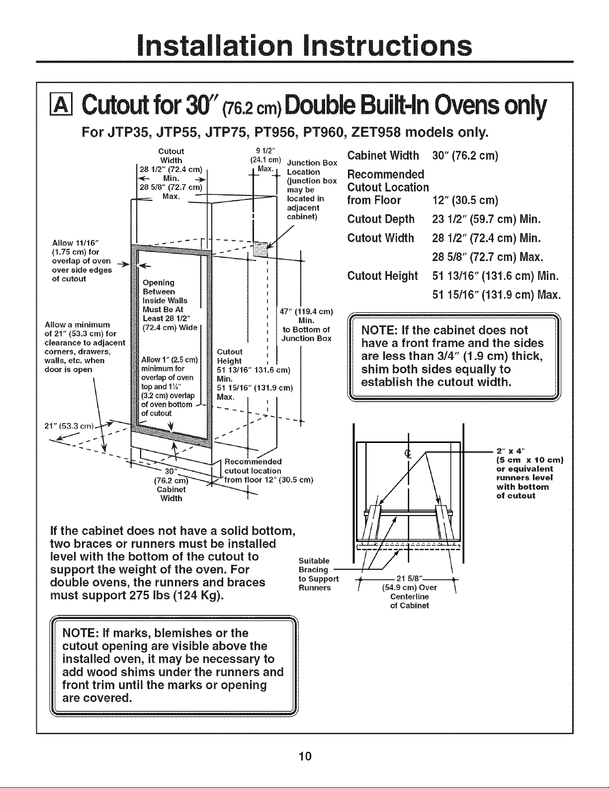
Cutoutfor30"(76.2cm)
For JTP35, JTP55, JTP75, PT956, PT960, ZET958 models only.
Allow 11116"
(1.75 cm) for
overlap of oven .__
over side edges
of cutout
Allow a minimum
of 21" (53.3 cm) for
clearance to adjacent
corners_ d rawers_
walls, etc. when
door is open
\
21" (53.3 cm)_
Cutout
Width
28 1/2" (72.4 cm)
Min. -,_
28 5/8" (72.7 cm)
Max.
Between I
Inside Walls I
Must Be At
Least 28 1/2"
(72.4 cm) Wide
AHow 1" (2.5 cm)
minimum for
overlap of oven
top and 11/4"
(3 2 cm) over ap Max
of oven bottom - I
_t Location
Cutout
Height
51 13/16" 131.6 cm)
Min.
51 15/16" (131.9 cm)
9 1/2"
(24.1 cm) Junction Box
n cabinet)
ofcutout " F- _-I
(junction box
may be
located in
adjacent
/"
47" (119.4 cm)
Min.
to Bottom of
Junction Box
Ovensonly
Cabinet Width
Recommended
Cutout Location
from Floor
Cutout Depth
Cutout Width
Cutout Height
NOTE: If the cabinet does not
have a front frame and the sides
are less than 314" (1.9 cm) thick,
shim both sides equally to
establish the cutout width.
30" (76.2 cm)
12" (30.5 cm)
23 1/2" (59.7 cm) Min.
28 1/2" (72.4 cm) Min.
28 5/8" (72.7 cm) Max.
51 13/16" (131.6 cm) Min.
51 15116" (131.9 cm) Max.
--_ 30_ I cutout location
(76.2 cm)"_;,_from f!oor 12" (30.5 cm)
Cabinet _'_..L,_.
Width I
/1 Recommended
if the cabinet does not have a solid bottom,
two braces or runners must be installed
level with the bottom of the cutout to
support the weight of the oven. For
double ovens, the runners and braces
must support 275 Ibs (124 Kg).
NOTE: If marks, blemishes or the
cutout opening are visible above the
installed oven, it may be necessary to
add wood shims under the runners and
front trim until the marks or opening
are covered,
Suitable
Bracing --
to Support
Runners
-- 2"x4"
(Scm xtOcrn)
or equiva|eut
runners |eve|
with bottom
of cutout
10
Page 11
Installation instructions
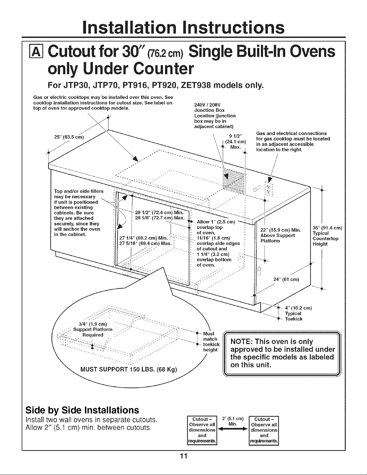
Cutoutfor 30"(76.2 Single lit-in
only Under Coun :r
For JTP30, JTPT0, PT916, PT920, ZET938 models only.
Gas or electric cooktops may be installed over this oven. See
cooktop installation instructions for cutout size. See label on
top of oven for approved cooktop models.
\
25" (63.5 cm)
Top and/or side fillers
may be necessary
if unit is positioned
between existing
cabinets. Be sure
they are attached
securely, since they
will anchor the oven
in the cabinet.
- 28 1/2" (72.4 cm) Min.
28 5/8" (72.7 cm) Max.
240V / 208V
Junction Box
Location (junction
box may be in
adjacent cabinet)
9 1/2"
(24.1 cm)
overlap top
Of oven_
-. 11/16" (1.8 cm)
_,"- overlap side edges
of cutout and
-- 1 114" (3.2 cm)
overlap bottom
Of oven,
(2.5 cm)
Ovens
Gas and electrical connections
for gas cooktop must be located
in an adjacent accessible
location to the right.
22" (55.9 cm) Min.
Above Support
Platform
36" (91.4 cm)
Typical
Countertop
Height
Side by Side Installations
Install two wall ovens in separate cutouts.
Allow 2" (5.1 cm) min. between cutouts.
NOTE: This oven is only
approved to be installed under
the specific models as labeled
on this unit.
Cutout - ] 2" (5.1 cm)
Observe all| Min.
dimensions_-,ql,,,,===,,,===,=,lm_"
and |
requirements.J
Observe all
dimensions
requirements.
Cutout -
and
24" (61 cm)
4" (10.2 cm)
Typical
Toekick
11
Page 12
Cabinetry
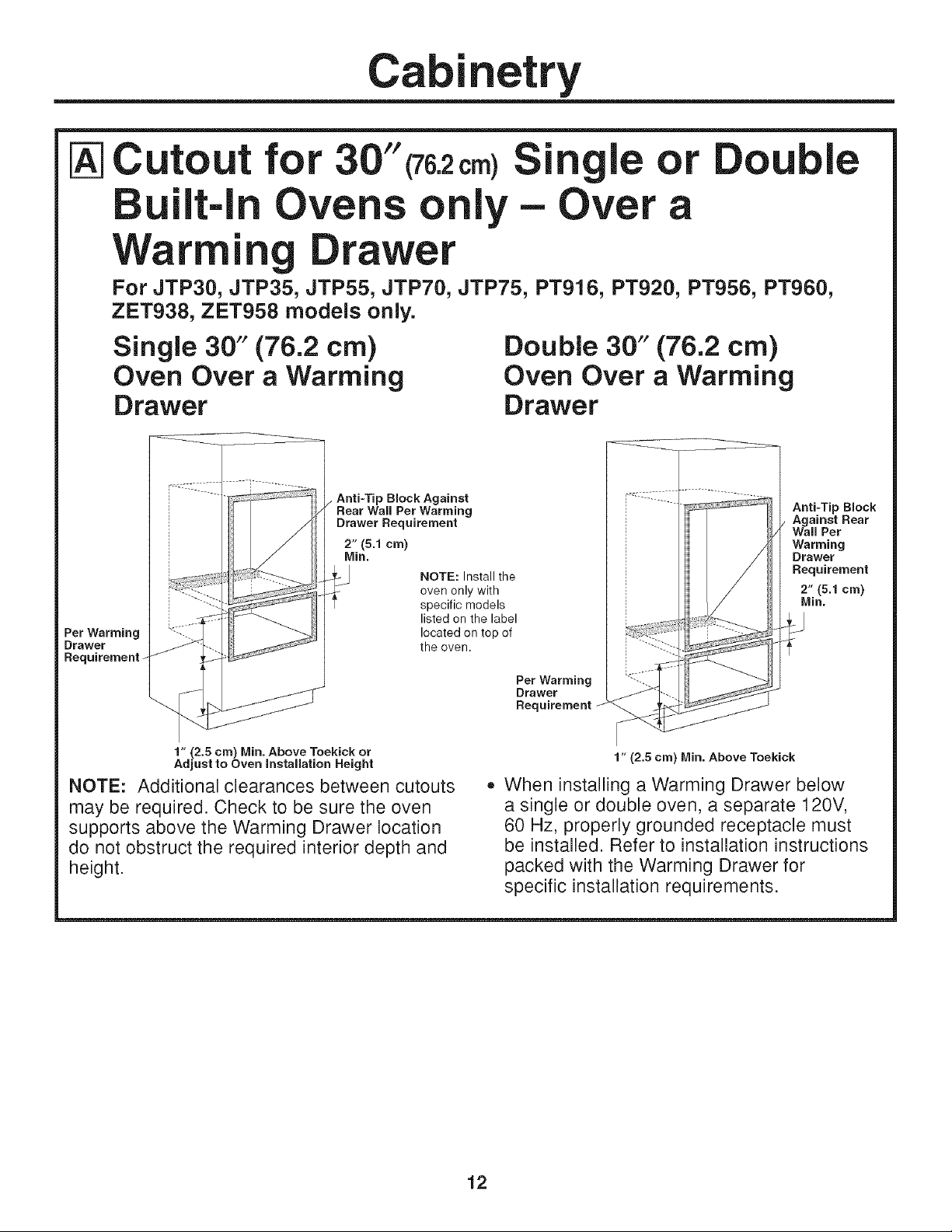
Cutout for 30"(76.2c_)Single or
For JTP30, JTP35, JTP55, JTP70, JTP75, PT916, PT920, PT956, PT960,
ZET938, ZET958 models only.
Single 30" (76.2 cm)
Oven Over a Warming
Drawer
Per Warming
Drawer
Requirement
L_i-in Ovens only- Over a
_rrning Drawer
Double 30" (76.2 cm)
Oven Over a Warming
Drawer
Rear Wall Per Warming
Drawer Requirement
Block Against
2" (5J cm)
IVlin.
NOTE: Install the
oven only with
specific models
listed on the label
located on top of
the oven.
Per Warming
Drawer
Requirement
Double
Anti-Tip Block
Against Rear
Wall Per
Warming
Drawer
Requirement
2" (5.1 cm)
IVlin.
1" (2.5 cm) Min. Above Toekick or
Adjust to Oven Installation Height
NOTE: Additional clearances between cutouts
may be required. Check to be sure the oven
supports above the Warming Drawer location
do not obstruct the required interior depth and
height.
1" (2.5 cm) Min. Above Toekick
When installing a Warming Drawer below
a single or double oven, a separate 120V,
60 Hz, properly grounded receptacle must
be installed. Refer to installation instructions
packed with the Warming Drawer for
specific installation requirements.
12
Page 13

Cabinetry
Cutoutfor 30"<76.2o_)SingleOvensonly-
BelowanAdvantiumor _-rowaveOven
or BetweenanAdvantiumor crowave
OvenandaWarmingDrawer
For JTP30, JTP70, PT916, PT920, ZET938 models only.
Single 30" (76.2 cm) Oven
Below an Advantium or
Microwave Oven
__" (5.1 cm) Min,
Note: Install the
oven only with
specific models
listed on the label
located on top of
the oven.
NOTE: The middle rail separating the two
openings may need to be larger than the 2"
(5.1 cm) m=nimum shown. Always refer to the
individual installation instructions packed with
each product for specific requirements.
Combined Advantium or Microwave
Oven and Wall Oven Installation:
When installed in combination with a
single wall oven, use separate electrical
junction boxes.
• Refer to the Advantium or microwave
oven installation instructions for electrical
requirements of that product.
These connections must be made
by a qualified electrician. All electrical
connections must meet National Electrical
Code or prevailing local codes.
Single 30" (76.2 cm) Oven
Between an Advantium or
Microwave Oven and a
Warming Drawer
Per Advantium
Microwave Oven
Requirement
Per Warming
Drawer
Req
NOTE: Additional clearances may be
required. Check to be sure the oven
supports above the Warming Drawer
do not obstruct the required interior depth
and height. The middle rail separating the
openings may need to be larger than the
2" (5.1 cm) minimum shown. Always refer to
the individual installation instructions packed
with each product for specific requirements.
WarmingDrawerCombinedwith
Advantiumor MicrowaveOvenand
SingleOven:
Install a separate 120V, 60Hz, properly
grounded receptacle, See installation
instructions packed with each product
for specific requirements,
2" (5.1 cm) Min.
2" (5.1 cm) Min.
13
Page 14

Installation instructions
Electrical Connections
ATTENTION iNSTALLER
All electric wall ovens must be hard wired
(direct wired) into an approved junction
box. A plug and receptacle is NOT permitted
on these products.
DO NOT shorten the flexible conduit.
The conduit strain relief clamp must be
securely attached to the junction box
and the flexible conduit must be securely
attached to the clamp. If the flexible
conduit will not fit within the clamp, do not
install the oven until a clamp of the proper
size is obtained.
NOTE TO ELECTRiCiAN: The 3 power
leads supplied with this appliance are
UL recognized for connection to heavier
gauge household wiring. The insulation
of these 3 leads is rated at temperatures
much higher than the temperature rating
of household wiring. The current carrying
capacity of the conductor is governed
by the wire gauge and the temperature
rating of the insulation around the wire.
Turn off the circuit breaker or remove
fuses to the oven branch circuit.
With the oven supported on a table or
platform in front of the cabinet opening,
connect the flexible conduit to the
electrical junction box as shown below.
Position the conduit in such a manner
that it will lie on top of the oven in
a natural loop when the oven is
installed. You will need to purchase
an appropriate strain relief clamp to
complete the connection of the conduit
to the junction box.
Junction Box
Location
Conduit II
WARNING: Improper
connection of aluminum house
wiring to copper leads can
result in an electrical hazard or fire.
Use only connectors designed for
joining copper to aluminum and follow
the manufacturer's recommended
procedure closely.
14
Place oven on a
support to assist i
connecting conduit
Strain Relief Clamp
(not included)
must be used at
Junction Box
Page 15

Installation instructions
New Construction and
Four=Conductor Branch
Circuit Connection
• When installing in new construction, or
• When installing in a mobile home, or
• When installing in a recreational vehicle, or
• When local codes do not permit grounding
through neutral:
a. Cut the neutral (white) lead from the crimp.
Re-strip the neutral (white) lead to expose
the proper length of conductor.
b. Attach the appliance grounding lead (green
or bare copper) in accordance with local
codes. If the residence grounding conductor
is aluminum, see WARNING on page 14.
c. Connect the oven neutral (white) lead to
the branch circuit neutral (white or gray)
in accordance with local codes, using a
wire nut.
Three=Conductor Branch
Circuit Connection
When connecting to a three-conductor branch
circuit, if local codes permit:
a. Connect the bare oven ground conductor
with the crimped neutral (white) lead to
the branch circuit neutral (white or gray
in color), using a wire nut.
[__ound and
\..j__ Jo.o.:, ooBox
boConnect the oven red lead to the branch
circuit red lead in accordance with local
codes, using a wire nut.
c. Connect the oven black lead to the branch
circuit black lead in accordance with local
codes, using a wire nut. If the residence
red, black or white leads are aluminum
conductors, see WARNING on page 14.
d. Install Junction Box Cover.
d. Connect the oven red lead to the branch
circuit red lead and the oven black lead to
the branch circuit black lead in accordance
with local codes, using wire nuts. If the
residence red, black or white leads are
aluminum conductors, see WARNING
on page 14.
e. Install Junction Box Cover.
15
Page 16

Installation instructions
Securing the Oven
m
In
e Openin
Sliding the Oven into the
Opening
a. Loop (do not tie) a 36" (91 cm) string
around the conduit before the oven is slid
into place. This will keep the conduit from
falling behind the oven.
Pull out on
string loop
while pushing
the oven into
the cabinet
b. Lift oven into cabinet cutout using the oven
opening as a grip. Carefully push against
oven front frame. Do not push against
outside edges.
Drilling the Pilot Holes and
Mounting the Oven
NOTE: Before drilling the pilot holes,
make sure the oven is pushed as far
back into the opening as it will go
and centered.
a. Drill through the mounting holes (top and
bottom) of the side trim, for the #8 screws
provided.
Mounting
Hole
Locations
(Hole
may vary)
The screws must
be a minimum of
1/4" (6 mm) from
the front of the
cutout.
c. As you slide the oven back, pull the string
so that the conduit will lie on top of the
oven in a natural loop.
d. When you are sure the conduit is out of the
way, slide the oven 3/4 way back into the
opening. Remove the string by pulling on
one end of the loop.
_k WARNING: Mounting
falling out of the cabinet causing
serious injury.
screws must be used. Failure to
do so could result in the oven
b. Secure the oven to cabinet with screws
provided.
NOTE: If the cabinet is particle board, you
must use #8 x 3/4" particle board screws.
These may be purchased at any hardware
store.
16
Page 17

Installation instructions
Preparing for the Bottom
Trim Installation
a. With oven installed, take the bottom trim
and center it on the bottom front edge of
the cabinet opening.
b. Using the trim
as a template,
mark the center
of each slot
(two total) where
the mounting holes
will be drilled.
c. Remove the trim.
d. Drill pilot holes into
the center of each
template mark.
For 27" (68.6 cm)
models with Lower
Trim in Position
Mark (2)
Hole Locations
here
* Remove models with
Lower Trim Lower Trim in
Before Position, Mark
Pre-drilling (2) Mounting
Mounting Hole Locations
Holes here
:or 30" (76.2 cm)
[_ Installing the Metal
Bottom Trim
a= Place the bottom metal trim centered over
the pre-drilled mounting holes. Tape the
edges of the trim down to maintain the
alignment.
b. Using two trim screws provided, secure
the bottom trim to the bottom edge of the
cabinet.
Trim Screw Locations for /Trim
27"(68._cm)modelswith _.._ 1'
Trim -..__
IMPORTANT: if this unit is ever
removed from the cabinet or the oven
is ever pulled out for service, the trim
must be removed first or damage to
the trim will occur.
._ , Side
Trim Screw Locations for
30" (76.2 cm) models with
Lower Trim
17
Page 18

Installation instructions
Replacing the Oven Door
NOTE: The oven door is heavy. You
may need help lifting the door high
enough to slide it into the hinge slots.
Do not lift the door by the handle.
Lift the oven door by
placing one hand on
each side. The door is
heavy, so you may need
help. Do not lift the door
by the handle.
F_ With the door at the same angle as
the removal position, which is most of
the way closed, seat the notch of the
hinge arm into the bottom edge of the
hinge slot. The notch of the hinge arm
must be fully seated into the bottom
of the slot.
Hinge Arm
Bottom Edge
of Slot
[=_ Open the oven door as far as it
[=_ Push the hinge locks up against the
[=_ Close the oven door.
will open.
front frame of the oven cavity, to the
locked position,
Hinge in
Locked Position
Notch of Hinge
Securely Fitted
into
Hinge Slot
Hinge Notch
18
Page 19

Installation instructions
Pre-Test C ec
Remove all protective film, if present,
and any stickers.
Check to be sure that all wiring is
secure and not pinched or in contact
with moving parts.
ist
Operation Checklist
Remove all items from the inside
of the oven.
Check that conduit is securely
connected to the junction box.
Turn on the power to the oven. (Refer
to your Owner's Manual.) Verify that
the bake and broil units, and all
cooking functions operate properly.
Check that the circuit breaker is not
tripped nor the house fuse blown.
Check that the bottom trim is installed
properly (see page 17).
Check to be sure the mounting screws
are installed and flush with the side trim
(see page 16).
NOTE TO ELECTRICIAN: The power
leads supplied with this appliance
are UL recognized for connections
to larger gauge household wiring.
The insulation of these leads is
rated at temperatures much higher
than the temperature rating of
household wiring. The current
carrying capacity of a conductor
is governed by the wire gauge and
also the temperature rating of the
insulation around the wire.
NOTE: ALUMINUM WIRING
See your Owner's Manual for
troubleshooting list.
19
WARNING: IMPROPER
A.
CONNECTION OF ALUMINUM
HOUSE WIRING TO THE COPPER
LEADS CAN RESULT IN AN
ELECTRICAL HAZARD OR FIRE.
B,
Splice copper wires to aluminum
wiring using special connectors
designed and UL approved for
joining copper to aluminum,
and follow the manufacturer's
recommended connector
procedure closely.
NOTE: Wire used, location and
enclosure of splices, etc., must
conform to good wiring practice
and local codes.
Page 20

Notes
20
Page 21

Horno de pared empotrado
Instrucciones
de instalacibn
I &Preguntas? Visite nuestro sitio en la Web: ge.com I
Modelos de 27" (68,6 cm)
JKS10, JKP30, JKP35, JKP55, JKP70, JKP75,
PK916, PK956, ZEK938, ZEK958
Modelos de 30" (76,2 cm)
JTP30, JTP35, JTP55, JTP70, JTP75, PT916,
PT920, PT956, PT960, ZET938, ZET958
Antes de empezar
Lea estas instrucciones cuidadosa y completamente.
• IMPORTANTE-Guarde estas
instrucciones y tengalas disponibles
para el inspector local.
• IMPORTANTE-observe todos
los c6digos y ordenanzas vigentes.
• Nota al instaladormCerci6rese de dejar
estas instrucciones con el propietario.
• Nota al consumidormGuarde estas
instrucciones para usarlas como
referencia en el futuro.
Partes incluidas
(l'apariencia puede variar)
• La instalacion apropiada es responsabilidad
del instalador y la falla del producto por una
instalacion incorrecta NO esta cubierta por
la garantia.
• NOTA--Este aparato debe estar conectado
a tierra adecuadamente.
•iATENCION AL
INSTALADORI
Todos los hornos electronicos de pared
deben ser cableados directamente en una
caja de conexion aprobada. Un "enchufe-
receptaculo" NO E8 permitido en estos
productos.
Materiales necesarios
4__ @ TLet__aSpar a
Tornillos para
instalaciSn (tornillos
para madera tipo
Phillips de cabeza
plana 8-18 x .750)
WBO7T10579 - SS
Montaje de moldura de rondo
metalica opcional de 27" (68,6 cm)
(en algunos modelos o pueden
adquirirse por separado)
31-10647-3 11-07JR
Moldura de fondo
metalica de 27"
(68,6 cm)
Montaje de moldura de
fondo metalica de 30"
(76,2 cm)
alambres
Abrazadera de alivio Caja de
de presion para conexion (_-'_
conducto de 1/2"
Cord6n de 36" (91 cm)
Herramientas
necesarios
Una broca de 1/8" (3 mm) para
taladro electrico o manual
Destornillador
de estrella
Page 22

Instrucciones de instalacibn
INSTRUCCIONES DE SEGURIDAD
IMPORTANTES
Para su seguridad
* Cerciorese de que su horno sea instalado
adecuadamente por un instalador calificado
o por un tecnico de servicio.
o Cerci6rese de que su homo este firmemente
instalado en un gabinete que este firmemente
adherido a la estructura de la casa. El peso
sobre la puerta del horno podria causar que el
horno se voltee resultando en lesiones. Nunca
permita que nadie se suba, se siente, se pare
o se cuelgue de la puerta del horno.
° Cerciorese de que los gabinetes y los
revestimientos de la pared alrededor del horno
puedan soportar las temperaturas (hasta 200°F
[93,3°C]) generadas por el horno.
ADVERTENCIA:
La energia el_ctrica hacia la linea
de suministro del horno debe ser
desconectada mientras se hacen las
conexiones. No hacer esto podria
resultar en lesiones graves e incluso
provocar la muerte.
Requisitos el ctricos
Este aparato debe abastecerse con la frecuencia
y el voltaje adecuados, y conectarse a un circuito
electrico individual con conexi6n a tierra con protecci6n
de un fusible o interruptor autom_.tico. Consulte la placa
de potencia ubicada en el marco del homo para
determinar la potencia del producto. Utilice el cuadro
a continuaci6n para determinar la protecci6n minima
recomendada para el circuito electrico especializado.
Recomendable
Potencia KW Potencia KW Tamafiodel circuito
240V 208V (Especializado)
<4,8 KW <4,1 KW 20 Amp
4,9 KW-7,2 KW 4,3 KW-6,2 KW 30 Amp
7,3 KW-9,6 KW 6,3 KW-8,3 KW 40 Amp
9,7 KW-12,0 KW 8,4 KW-10,4 KW 50Amp
Requisitos el ctricos
cont.
La placa de potencia se encuentra en la moldura lateral
del homo, el marco lateral frontal del homo o el marco
frontal inferior del homo.
Ubicaci6n
de la placa
de potencia
! ................... I
Recomendamos que el cableado y la conexi6n electrica
de su homo los realice un electricista calificado.
Despues de la instalaci6n, pida al electricista que le
muestre la ubicacion del interruptor principal del homo.
Consulte con su compafiia de servicios local
para obtener los c6digos electricos que sean aplicables
en su Area. No hacer el cableado de su homo de
manera apropiada, respetando los c6digos vigentes,
podria resultar en condiciones peligrosas. Si no existen
c6digos locales, su aparato debe usar un cableado y
fusibles que cumplan con los requisitos,,del C6digo
Electrico Nacional, ANSl/NFPA No. 70-Ultima edici6n.
Usted puede obtener una copia de este c6digo
escribiendo a:
National Fire Protection Association
Batterymarch Park
Quincy, MA 02269
A partir del lro. de enero de 1996, el C6digo
Electrico Nacional requiere que todas las
construcciones nuevas, pero no existentes, usen
una conexi6n de 4 conductores hacia cualquier horno
electrico. Cuando instale un homo electrico en una
construcci6n nueva, casa m6vil, vehiculo de recreaci6n
o un Area donde los c6digos locales prohiban
la conexi6n a tierra a traves del conductor neutro, siga
las instrucciones en la Secci6n CONSTRUCCIONES
NUEVAS Y CONEXlONES DE CIRCUlTOS RAMALES
DE 4 CONDUCTORES.
Usted debe usar un sistema electrico de tres alambres,
monof_.sico, A.C. 208Y/120 voltios o 240/120 voltios,
60 Hertz. Si hace una conexi6n a alambres de aluminio,
debe usar conectores adecuadamente instalados que
esten aprobados para ser utilizados con cableados
de aluminio.
-- =
Page 23

Instrucciones de instalacibn
p Lista de control antes de la instalacibn
No es necesario retirar la puerta para la
iTODA LA INFORMACION PARA LA
INSTALACION EN LAS PAGINAS
SIGUIENTES ES PARA SER USADA EN
LA INSTALACION DE HORNOS DE UNA
O DOS UNIDADES!
Retire los rnateriales de ernbalaje. Revise
detr_.s de las bisagras y debajo del fondo
falso. Retire las etiquetas de la puerta, el
pl_.stico de las rnolduras y panel, todas las
cintas alrededor del homo, y todos de los
tornillos de envio que asegure el homo a
la alrnohadilla de la base.
-<_
instalaci6n del producto, pero hacerlo facilita
la instalaci6n. Para retirar la puerta:
Abra la puerta del horno hasta el m_.ximo.
Ernpuje los topes de
las bisagras hacia
/_ Posici6n
abierta de
la bisagra
abajo, hacia el
marco de la puerta
hasta la posici6n
abierta. Esto podria
requerir el uso de un
Brazo de
la bisagra
destornillador piano.
iNO LEVANTE LA PUERTA POR
LA EMPUNADURA!
L -- _-J
Parrillas del
homo
_ Paquete de
instrucciones
Abra la puerta del horno y extraiga el paquete
de instrucciones y las parrillas del homo.
Extraiga las instrucciones de instalaci6n del
paquete y lealas cuidadosarnente antes de
ernpezar la instalaci6n.
Cerci6rese de guardar bien todas las
instrucciones, Manual del propietario,
Instalaci6n, etc. para referencia en el futuro.
?
Coloque las rnanos en arnbos
lados de la puerta, cierre la
puerta del homo hasta la
posici6n de rernoci6n, que
est,. cerrado la mayor parte
del tiernpo.
Levante la puerta
y hale hacia fuera
hasta que los brazos
de la bisagra salgan
de la ranuras.
Bisagra sale
de la ranura
NOTA: La puerta del horno es muy pesada.
Asegurese de tenerla bien agarrada antes de
levantarla de las bisagras. Tenga cuidado una vez
que retire la puerta. No acueste la puerta sobre la
empu_adura; esto podria causar marcas y rayas.
[_ oloque el horno sobre la mesa o plataforrna
al nivel de la abertura del corte. (La plataforrna
debe soportar 150 libras [68 Kg] para hornos
de una unidad y 275 libras [124 Kg] para
hornos de dos unidades.)
Extraiga la moldura de fondo de la parte
superior del horno. La misma ser_. instalada
al final de la instalaci6n. La rnoldura de fondo
est,. envuelta por separado y pegada a la
parte superior de la unidad.
Page 24

Instrucciones de instalacibn
l-A-]Corte para los hornos de una
unidad de 27"(68,6 cm)solamente
Para los modelos JKS10, JKP30, JKP70, PK916, ZEK938 solamente.
5" (12,7 cm)
M_x. espacio para
el lado izquierdo Ancho del
oderecho gabinete 27" (68,6 cm)
Ancho del_ ¢ Ubicaci6n de la
gabinete _ _ caja de conexion
27" (68,6 cm) i
Ancho
del corte
25" (63,5 cm) Min.
Permita 1" (2,5 cm)
de sobrepaso
del horno
sobre los bordes
laterales del
2" x 4"
(5 cm x 10 cm
o correderas
equivalentes
niveleada con
el rondo del corte
20" (50,8 cm) ......
Permita un minimo
de 20" (50,8 cm) de
espacio para las
esquinas, cajones,
paredes, etc.,
adyacentes cuando
la puerta est_ abierta
/
25 1/4" (64,1 cm)
Permita _n
minimo de
1" (2,5 cm) para
el sobrepaso
Ldel horno por
encima y debajo
del corte
"i_'
! 22" (55,9 cm)
Min. Sobre
el riel de
iAItura la base
idel corte I
i27 5/8" (70,2 cm) Min. Altura
__n alternaiiiiii!i_i!iii}(!!_l! '4 cm)M_x.
"_ I Ubicacion de la caja -
Ubicaci6n Puede requerirse
recomendada el acceso desde
para el corte el gabinete adyacente
desde el
piso 32 1/2"
(82,6 cm)
Si el gabinete no tiene un fondo sblido,
entonces se deben instalar dos abrazaderas o
correderas nivelada con el fondo del corte para
sostener el peso del horno. Para hornos de una
unidad las correderas o abrazaderas deben
soportar 150 libras (68 Kg).
Ubicacion
recomendada
para el corte
desde el piso
Profundidad
del corte
Ancho del corte
de corte
NOTA: Si el gabinete no tiene
un marco frontal y los lados
son menores de 3/4" (1,9 cm)
en grosor, coloque ambos
lados en linea para establecer
el ancho del corte.
32 1/2" (82,6 cm)
23 1/2" (59,7 cm) Min.
25" (63,5 cm) Min.
25 1/4" (64,1 cm) Mbx.
27 5/8" (70,2 cm) Min.
28 1/8" (71,4 cm) Mbx.
2" x 4" (5 cm x 10 cm) o
correderas equivalentes
niveleada con el fondo
del corte
1
NOTA: Si las marcas, imperfecciones o
la abertura del corte son visibles por
encima del horno instalado, quiz_s sea
necesario agregar relleno debajo de las
correderas y moldura delantera hasta
que se cubran.
24" (61 cm)
!
I_- 18" (45,7 cm)
•_ 27" (68,6 cm)
Estos hornos no estzin aprobados
para las instalaciones apilables.
Page 25

Instrucciones de instalacibn
I-A-1Cortepara los hornos de dos
unidades de 27"(68,6 cm) solamente
Para los modelos JKP35, JKP55, JKP75, PK956, ZEK958 solamente.
5" (12,7 cm)
Permita 1" (2,5 cm)
para sobrepaso del
horno sobre los
bordes laterales --
del corte
2" x 4"
(5 cm x t0 cm)
o correderas
equivalentes
M&x. espacio para
el lado izquierdo
o derecho
Ancho del _
_ gabinete _ J
27" (68,6 cm). J.
i--_Lr
t Anchodel I -i-._ _/-
I corte 25" '_,i'_
25 1/4" (64,1 cm) M_x.
Ubicaci6n
de la caja recomendada
de conexi6n para el corte
44" (111,8 cm) Min.
sobre el riel de Ancho del corte
la base
Ancho del
gabinete
Ubicaci6n
desde el piso
Profundidad
del corte
Altura de corte
27" (68,6 cm)
13 114"(33,7 cm)
23 518" (60 cm) Min.
25" (63,5 cm) Min.
25 1/4" (64,1 cm) Max.
49 11/16" (126,2 cm) Min.
50 1/8" (127,3 cm) Max.
20" (50,8
Permita un minimo
de 20" (50,8 cm) de
espacio para las
esquinas, cajones,
paredes, etc.,
adyacentes cuando
la puerta estd abierta
j_oJ-
ooooi -'I
Permita un minimo Ubicaci6n
de 1" (2,5 cm) para recomendada para
. el sobrepaso el corte desde el
del homo por encima piso 13 1/4" (33,7 cm)
y debajo del corte /
Si el gabinete no tiene un fondo sblido,
entonces se deben instalar dos abrazaderas o
correderas nivelada con el fondo del corte para
sostener el peso del horno. Para hornos de dos
unidades, las correderas y abrazaderas deben
soportar 300 libras (135 Kg).
NOTA: Si las marcas, imperfecciones o
la abertura del corte son visibles por
encima del horno instalado, quiz_s sea
necesario agregar relleno debajo de las
correderas y moldura delantera hasta
que se cubran.
Abrazaderas
de soporte
adecuadas
para las
correderas --
NOTA: Si el gabinete no tiene
un marco frontal y los lados
son menores de 3/4" (1,9 cm)
en grosor, coloque ambos
lados en Iinea para establecer
el ancho del corte.
2" x 4" (5 cm
x 10 cm) o
correderas
equivalentes
niveleada
con el fondo
del corte
Linea de centro
sobre gabinetes
Page 26

Instrucciones de instalacibn
Corte para los hornos de una
unidad-debajo de la superficie del
gabinete de 27"(68,6cm)solamente
Para los modelos JKS10, JKP30, JKP70, PK916, ZEK938 solamente.
Las estufas el_ctricas o de gas se
pueden instalar sobre este horno.
Consulte las instrucciones de la estufa
para el tamaho del corte. Consulte la
etiqueta encima del horno para los
modelos de estufas aprobados.
25" (63,5 cm)
Material de relleno
para la parte superior
y/o lados
necesario si la unidad
esta ubicada entre
gabinetes existentes.
AsegQrese de
que este pegado
firmemente ya que
este anclara el homo
en el gabinete.
25" (63,5 cm) Min.
25 1/4" (64,1 cm) Mbx.
1.
27 5/8" (70,2 cm) Min.
28 118" (71,4 cm) M_x. :
s
Ubicaci6n de la
caja de conexi6n
240V / 208V
Permita 1" (2,5 cm)
para sobrepaso del
horno por encima del
horno et debajo del
i
horno et 1" (2,5 cm)
para sobrepaso del
horno en los bordes
laterals
5" (12,7 cm)
M_x. espacio Las conexiones de gas y
para el lado el_ctricas para una estufa a
izquierdo o gas deben estar ubicadas en
derecho un lugar adyacente de f_cil
_- acceso en el lado derecho.
22" (55,9 cm) Min.
Por encima de la
plataforma de
soporte
24" (61 cm)
36" (91,4 cm)
Altura tipica del
gabinete
Debe equiparar
la altura del
z6calo
4" (10,2 cm)
Zocalo tipico
Page 27

Gabinetes
Disyuntor para 27"(68,6 cm) solamente
para hornos individuales o dobles
empotrados- Sobre una gaveta de
calentamiento
Para los modelos JKS10, JKP30, JKP35, JKP55, JKP70, JKP75, PK916,
PK956, ZEK938, ZEK958 solamente.
Horno individual de 27"
(68,6 cm) sobre una
gaveta de calentamiento
Bloque
estable contra
la pared trasera
para la gaveta de
calentamiento
requisitos
2" (5,1 cm)
Min,
Para la
gaveta de
calentamiento
requisitos
1" (2,5 cm) Min. Por encima del
z6calo o ajustar a la altura de la
instalaci6n del horno
NOTA: Puede necesitarse una separacion
adicional entre los disyuntores. Verifique para
asegurarse de que los apoyos del horno por
encima de la ubicacion de la gaveta de
calentamiento no dificulten la profundidad
y altura interior requerida.
Horno doble de 27"
(68,6 cm) sobre una
gaveta de calentamiento
NOTA: Instale el
horno solo con los
modelos especificos
enumerados en la
etiqueta que se ubica
en la parte superior
del homo.
Para la
gaveta de
calentamiento
requisitos
Para la instalacion de una gaveta de
calentamiento por debajo de un horno
individual o doble, debe instalarse un
receptaculo con conexion a tierra, separado
de 120V, 60Hz. Consulte las instrucciones
para la instalacion remitidas con la gaveta
de calentamiento para obtener los requisitos
especificos de instalacion.
Bloque
estable
contra
la pared
trasera para
la gaveta de
ealentamiento
requisitos
2" (5,1 cm)
Min.
1" (2,5 cm) Min. Por encima del z6calo
Page 28

Gabinetes
I_1Disyuntorpara27"(68,6cm)Solamente parahornos
individuales- DebajodeunAdvantiumodeun
hornodemicroondasoEntreunhornoAdvantiumo
unhornodemicroondasyGavetadecalentamiento
Para los modelos JKS10, JKP30, JKP70, PK916, ZEK938 solamente.
Hornoindividualde27"(68,6cm)
debajodeunhornoAdvantiumo
unhornodemicroondas
Por Advantium o horno
de microondas requisitos
NOTA:Elcarril del medioque separalas dos aberturas
puedennecesitarser ma.sgrandeque el de3" (7,6cm)
deminimoque se muestra.Siempreconsulte
las instruccionespara la instalacionque se remiten
concadaproductoparaobtenerlosrequisitosespecificos.
Instalacionparaelhornocombinado
Advantiumohornodemicroondasy
depared:
Paralainstalacionen combinacionconunhomo
individualde pared,utiliceuna cajadeconexiones
electricasseparada.
• Consultelasinstruccionesde instalaciondel homo
Advantiumo delhomo de microondaspara obtener
los requisitosde eseproducto.
• Un electricistaautorizadodeberealizarestas
conexiones.Todaslasconexioneselectricasdebe
cumplircon las normasdel CodigoElectricoNacional
o los codigoslocalesvigentes.
2" (5,1 cm) Min.
Nota: Instale el
horno solo con los
modelos especificos
enumerados en la
etiqueta que se
ubica en la parte
superior del homo.
Hornoindividualde27"(68,6cm)
EntreunhornoAdvantiumo
unhornodemicroondasy
unagavetadecalentamiento
Por Advantium o horno
de microondas requisitos
Por gaveta
calentamiento
requisitos
NOTA:Puede necesitarseuna separacionadicional
entre los disyuntores.Verifiquepara asegurarsede que
losapoyosdel homo porencima dela ubicacionde
la gavetadecalentamientono dificultenla profundidad
y alturainteriorrequerida.El carrildel medioquesepara
lasdosaberturaspueden necesitarser ma.sgrandeque
el de2" (5,1 cm) deminimoque se muestra.Siempre
consultelasinstruccionesparala instalacionque se
remitencon cada productoparaobtener los requisitos
especificos.
Gavetadecalentamientocombinada
conAdvantiumo hornodemicroondas
yhornoindividual:
Instaleun recepta.culoseparadode 120V,60Hz,
adecuadamentecon conexi6na tierra. Consulte
lasinstruccionesdeinstalacionremitidasconcada
productoparaobtener los requisitosespecificos.
2" (5,1 cm) Min.
2" (5,1 cm) Min.
Page 29

Instrucciones de instalacibn
Corte para los hornos de una unidad
de 30"(76,2 cm) solamente
Para los modelos JTP30, JTP70, PT916,
Ancho 9 1/2" de la caja
del corte (24,1 cm) de conexi6n gabinete
28 1/2" Mbx_ (la caja
(72,4 cm) Min. -_ de conexi6n Ubicaci6n
28 518" _ / puede estar recomendada
(72,7 cm) -- . ubicada en para el corte
"=== M_x. -- _ un gabinete
I adyacente) desdeel piso
Ubicacion Ancho del
I / Profundidad
Permita 11/16"
(1,75 cm) para
sobrepaso del "_
horno sobre los
bordes laterales
del corte
Permita un minimo del horno por
de 21" (53,3 cm) de encima y 1W"
espacio para las (3,2 cm) por
esquinas, cajones, debajo del corte
paredes, etc.,
adyacentes cuando Ancho del
la puerta est_ abierta gabinete
entre los I
paredes I
interiores I
debeestar I
(72,4 cm)
de ancho
Permita un mlnlmo
de 1" (2,5 cm) para
el sobrepaso
30" (76,2 cm)
del corte i 22" (55,9 cm)
27 1/4" _, la parte
(69,2 cm) Min. inferior
27 5/16" de la caja
(69,4 cm) Mbx. de conexion
Ubicaci6n (1,9cm) en grosor,coloque ambos lados
recomendada para
el corte desde el en linea para establecer el ancho del corte.
Si el gabinete no tiene un fondo sblido,
entonces se deben instalar dos abrazaderas
o correderas nivelada con el fondo del corte Abrazaderas
para sostener el peso del horno. Para hornos de soporte
de una unidad, las correderas o abrazaderas para las
deben soportar 150 libras (68 Kg). correderas--
NOTA: Si las marcas, imperfecciones o
la abertura del corte son visibles por
encima del horno instalado, quiz_s sea
necesario agregar relleno debajo de las
correderas y moldura delantera hasta
que se cubran.
Estos hornos no estzin aprobados
para las instalaciones apilables.
--__+
Min. hasta
"- I'_ --NOTA:Si el gabinete no tiene un marco
I frontal y los lados son menoresde3/4"
i
adecuadas
Instalaciones de lado a lado
Instale dos hornos en disyuntores separados.
Deje 2" (5,1 cm) min. entre disyuntores.
Disyuntor- I 2"(5,1cm)
Observe I _ Min.
todas las I
dimensiones
y requisitos.
PT920, ZET938 solamente.
30" (76,2 cm)
32 112"(82,6 cm)
del corte
Ancho del corte
Altura de corte
_-_54,9 21516"
centro sobre
gabinetes
23 112" (59,7 cm) Min.
28 112"(72,4 cm) Min.
28 518"(72,7 cm) Max.
27 1/4" (69,2 cm) Min.
27 5/16" (69,4 cm) Max.
cm) Linea de \
Disyuntor -
Observe
todas las
dimensiones
y requisitos.
-- 2" x 4"
(5 cm x 10
Cm) O
correderas
equivalentes
niveleada
con el
fondo
del corte
Page 30

Instrucciones de instalacibn
Corte para los hornos de dos
unidades de 30"(76,2 cm)solamente
Para los modelos JTP35, JTP55, JTP75, PT956, PT960, ZET958 solamente.
Ancho
del corte
28 1/2"
(72,4 cm) Min.
_r- 28 5/8"
(72,7 cm) M&x.
Permita 11/16"
(1,75 cm) para
sobrepaso del
horno sobre los
bordes laterales
del corte
Permita un minimo
de 21" (53,3 cm)
de espacio para
las esquinas,
cajones, paredes,
etc., adyacentes
cuando la puerta
est_ abierta
entre los [
paredes I
interieres [
debe e.star [
(72,4 cm)
de ancho
Permita un
minimo de 1"
(2,5 cm) para
el sobrepaso (131,9 cm_ M&x I
de horno por " " "
encima y 11/4" i
(3,2cm)por I : I
debajo _j [ ' I
21" )_- _
(53,3 cm
Si el gabinete no tiene un fondo sblido,
entonces se deben instalar dos abrazaderas
o correderas nivelada con el fondo del corte
para sostener el peso del horno. Para hornos
de dos unidades, las correderas y abrazaderas
deben soportar 275 libras (124 Kg).
del corte ...... L i I
A_cho del_'_ I para el corte desde
_ga_l;ine_e' _1 piso 12" (30,5 cm)
30" (76,2 cm)
9 112" (24,1 cm) Ubicaci6n
M&x.
I
F adyacente)
I
I
I
I
I
I
I
47" (119,4 cm)
Altura
del corte
51 13/16"
(131,6 cm) Min,
51 15/16"
/ I Ubicacion recomendada
Min. hasta
la parte
inferior de
la caja de
conexi6n
de la caja
de conexion
(la caja
de conexion
puede estar
ubicada en
un gabinete
Ancho del
gabinete
30" (76,2 cm)
Ubicaci6n
recomendada
para el corte
desde el piso
12" (30,5 cm)
Profundidad
del corte
Ancho del corte
23 112"(59,7 cm) Min.
28 112"(72,4 cm) Min.
28 518"(72,7 cm) Max,
Altura de corte
51 13/16" (131,6 cm) Min.
51 15/16" (131,9 cm) Max.
NOTA: Si el gabinete no tiene un marco
frontal y los lados son menores de 314"
(1,9 cm) en grosor, coloque ambos lados
en linea para establecer el ancho del corte.
-- 2" x 4"
(5 cm x 10
cnl) O
correderas
equivalentes
niveleada
con el
fondo
del corte
Abrazaderas
de soporte
adecuadas
para las
correderas --
21 5/8"-----_
(54,9 cm) Linea de \
centro sobre
gabinetes
NOTA: Si las marcas, imperfecciones o
la abertura del corte son visibles por
encima del horno instalado, quiz_s sea
necesario agregar relleno debajo de las
correderas y moldura delantera hasta
que se cubran.
10
Page 31

Instrucciones de instalacibn
Corte para los hornos de una
unidad -debajo de la superficie del
gabinete de 30"(76,2 cm)solamente
Para los modelos JTP30, JTP70, PT916, PT920, ZET938 solamente.
Las estufas el_ctricas o de gas se pueden instalar sobre este
horno. Consulte las instrucciones de la estufa para el tamaho del
corte. Consulte la etiqueta encima del horno para los modelos de
estufas aprobados.
Ubicaci6n de la caja
de conexi6n 240V /
208V (la caja
de conexi6n puede
estar ubicada en un
gabinete adyacente)
9 1/2"
(24,1 cm)
M_x.
Las conexiones de gas y el_ctricas
para una estufa a gas de deben estar
ubicadas en un lugar adyacente de
f&cil acceso en el lado derecho.
Material de relleno
para la parte superior
y/o lados podria ser
est_ ubicada entre
gabinetes existentes.
Asegurese de
que estd pegado
firmemente ya que
este anclar_ el horno
en el gabinete.
- 28 112" (72,4 cm) Min
28 518" (72,7 cm) M_x..
27 114" (69,2 cm) Min.
27 5116" (69,4 cm) M_x. :::L_.
Permita 1" (2,5 cm)
para el sobrepaso
del horno por
encima, 11/16"
:: (1,6 cm) para el
sobrepaso de los
bordes laterales
del corte y 1 1/4"
(3,2 cm) para
el sobrepaso
del horno debajo
22" (55,9 cm) Min.
Por encima de
la plataforma
de soporte
(10,2 cm)
Z6calo tipico
36" (91,4 cm)
Altura tipica del
gabinete
NOTA: Este horno estb
aprobado solo para
instalarse bajo los modelos
especificos indicados en
esta unidad.
Instalaciones de lado a lado
Instale dos hornos en disyuntores separados. Deje 2" (5,1 cm) min.
entre disyuntores.
11
Disyuntor - 2"(5,1cm)
Observe I - Min.
todas las
dimensiones
y requisitos.
Disyuntor -
Observe
todas las
dimensiones
y requisitos.
Page 32

Gabinetes
Disyuntor para 30"(76,2 cm)solamente
para hornos individuales o dobles
empotrados- Sobre una gaveta de
calentamiento
Para los modelos JTP30, JTP35, JTP55, JTP70, JTP75, PT916, PT920,
PT956, PT960, ZET938, ZET958 solamente.
Horno individual de 30"
(76,2 cm) sobre una
gaveta de calentamiento
Bloque estable
contra la pared
trasera para la gaveta
de calentamiento
requisitos
2" (5,1 cm)
Min.
Para la
gaveta de
calentamiento
requisitos
1" (2,5 cm) Min. Por encima del
z6calo o ajustar a la altura de la
instalaci6n del horno
NOTA: Puede necesitarse una separacion
adicional entre los disyuntores. Verifique para
asegurarse de que los apoyos del horno por
encima de la ubicacion de la gaveta de
calentamiento no dificulten la profundidad
y altura interior requerida.
Horno doble de 30"
(76,2 cm) sobre una
gaveta de calentamiento
NOTA: Instale el
horno solo con los
modelos especificos
enumerados en la
etiqueta que se ubica
en la parte superior
del homo.
Para la
gaveta de
calentamiento
requisitos
Para la instalacion de una gaveta de
calentamiento por debajo de un horno
individual o doble, debe instalarse un
receptaculo con conexion a tierra, separado
de 120V, 60Hz. Consulte las instrucciones
para la instalacion remitidas con la gaveta
de calentamiento para obtener los requisitos
especificos de instalacion.
Bloque estable
contra la pared
trasera para
la gaveta de
calentamiento
requisitos
2" (5,1 cm)
Min.
1" (2,5 cm) Min. Por encima del z6calo
12
Page 33

Gabinetes
Disyuntorpara30"(76,2cm)Solamente parahornos
individuales- DebajodeunAdvantiumodeun
hornodemicroondasoEntreunhornoAdvantiumo
unhornodemicroondasyGavetadecalentamiento
Para los modelos JTP30, JTP70, PT916, PT920, ZET938 solamente.
Hornoindividualde30"(76,2cm)
debajodeunhornoAdvantiumo
unhornodemicroondas
Por Advantium o horno
de microondas requisitos
2" (5,1 cm) Min. microondas requisi
Nota: Instale el i I
horno solo con los I II
modelos especificos I IL_
L_.:_:_---.... etlqueta qua se ....... II
NOTA:Elcarril del medioque separalas dos aberturas
puedennecesitarser ma.sgrandeque el de 2" (5,1cm)
deminimoque se muestra.Siempreconsulte
las instruccionespara la instalacionque se remiten
concadaproductoparaobtenerlosrequisitosespecificos.
Instalacionparael hornocombinado
Advantiumo hornode microondasy
depared:
Paralainstalacionen combinacionconunhomo
individualde pared,utiliceuna cajadeconexiones
electricasseparada.
• Consultelasinstruccionesde instalaciondel homo
Advantiumo delhomo de microondaspara obtener
los requisitosde eseproducto.
• Un electricistaautorizadodeberealizarestas
conexiones.Todaslasconexioneselectricasdebe
cumplircon las normasdel CodigoElectricoNacional
o los codigoslocalesvigentes.
enumerados en la I ,_....... 111
ubica en la parte
superior del homo,
Hornoindividualde30"(76,2cm)
EntreunhornoAdvantiumo
unhornodemicroondasy
unagavetadecalentamiento
Por Advantium
2" (5,1 cm) Min.
2" (5,1 cm) Min.
Por gay
calentamiento _1_ J
requisitos
NOTA:Puede necesitarseuna separacionadicional
entre los disyuntores.Verifiquepara asegurarsede que
losapoyosdel homo porencima dela ubicacionde
la gavetadecalentamientono dificultenla profundidad
y alturainteriorrequerida.El carrildel medioquesepara
lasdosaberturaspueden necesitarser ma.sgrandeque
el de2" (5,1 cm) deminimoque se muestra.Siempre
consultelasinstruccionesparala instalacionque
se remitenconcada productoparaobtener
losrequisitosespecificos.
Gavetadecalentamientocombinada
conAdvantiumo hornodemicroondas
yhornoindividual:
Instaleun recepta.culoseparadode 120V,60Hz,
adecuadamentecon conexiona tierra. Consulte
lasinstruccionesdeinstalacionremitidasconcada
productoparaobtener los requisitosespecificos.
13
Page 34

Instrucciones de instalacibn
IBIConexiones el ctricas
ATENCION AL
INSTALADOR:
Todos los hornos electricos de pared deben
ser cableados directamente en una caja
de conexibn. Una "enchufe-recept_iculo"
NO ES permitido en estos productos.
NO acorte el conducto flexible. La
abrazadera para controlar la presibn debe
estar firmemente adherida a la caja de
conexion y el conductor flexible debe estar
firmemente adherido a la abrazadera. Si el
conducto flexible no se ajusta al interior
de la abrazadera, no instale el horno hasta
que obtenga el tamafio apropiado.
NOTA AL ELECTRICISTA: Los 3 alambres
electricos proporcionados con este aparato
son reconocidos por la UL para conexiones
a cableado residencial de mayor calibre.
El aislante de estos 3 alambres supera las
especificaciones de temperatura indicadas
para cableado residencial. La capacidad
actual de conduccion del cable depende
del calibre del cableado y de la
clasificacibn de la temperatura del
aislamiento alrededor del alambre.
Desconecte el interruptor del circuito
o retire los fusibles que alimentan el
circuito ramal del horno.
Con el horno enfrente de la abertura del
gabinete, sobre una mesa o plataforma
conecte el conducto flexible a la caja
de conexi6n como se muestra en la
figura. Coloque el conducto de manera
que quede apoyado sobre la parte
superior del horno en forma de bucle
natural cuando se instale el homo.
Usted necesitara comprar una
abrazadera liberadora de presi6n para
completar la conexi6n del conducto
hacia la caja de conexi6n.
Ubicacibn de la
caja de conexi6n
conexi6n a
Conducto
__tierra
res de
ADVERTENCIA:
Una conexion inapropiada del
cableado de aluminio residencial
con cobre, podria resultar en un
peligro electrico o hasta en incendio.
Use solamente conectores disefiados
para unir cobre con aluminio y siga las
recomendaciones del fabricante con
mucho cuidado.
14
Coloque el horno en
el soporte para ayudar
en la conexion del
conductor -_
Abrazadera liberadora
de presi6n (no incluida)
debe usarse en la caja
de conexion
Page 35

Instrucciones de instalacibn
[B3-] Conexibn para nueva
construccibn y de circuito
ramal de cuatro conductores
• Cuando se instale en una construccion nueva, o
• Cuando se instale en una casa movil, o
• AI instalar en un vehiculo de recreacion, o
• Cuando los codigos locales no permitan hacer
conexion a tierra a traves de un cable neutro:
a. Corte la punta del alambre neutro (blanco)
del empalme. Pele la punta del alambre neutro
(blanco) hasta exponer la extension apropiado
del conductor.
Alambres de
.conexion a tierra
caja
b. Conecte el alambre de conexon a tierra (verde
o cobre descubierto) de acuerdo a los codigos
locales. Si el conductor de conexion a tierra
de la residencia es de aluminio, consulte
la ADVERTENCIA en la pagina 14.
i--- -i
Cuando conecte un circuito ramal de
3 conductores, si los codigos locales Io
permiten:
a. Conecte el alambre descubierto del horno
b=
C=
de tres conductores
con el alambre neutro (blanco) del circuito
ramal (blanco o gris), usando una tuerca
para alambres.
Alambres de
conexion a tierra
y neutro
-- Cubierta de la caja
de conexi6n
Conecte el alambre rojo del horno al
alambre rojo del circuito ramal, usando
una tuerca para alambres.
Conecte el alambre negro del horno
al alambre negro del circuito ramal de
acuerdo a los codigos locales, usando
una tuerca para alambre. Si los alambres
rojos, negros o blancos de la residencia
son conductores de aluminio, consulte
la ADVERTENCIA en la pagina 14.
Conexibn de circuito ramal
c. Conecte el alambre neutro del horno (blanco) al
circuito ramal neutro (blanco o gris) de acuerdo
con los codigos locales, usando una tuerca para
alambres.
d. Conecte el alambre rojo del horno al alambre
rojo del circuito y el alambre negro del horno al
alambre negro del circuito de acuerdo con los
codigos locales, usando las tuercas para
alambres. Si los alambres rojos, negros o
blancos de la residencia son conductores de
aluminio, consulte la ADVERTENCIA en la
pagina 14.
e. Instale la cubierta de la caja de conexion.
d. Instale la cubierta de la caja de conexi6n.
15
Page 36

Instrucciones de instalacibn
Posicibn firme del horno en la abertura
Cbmo deslizar el horno en
'---' el interior de la abertura
a. Coloque (sin atar) una cuerda de 36"
(91 cm) alrededor del conductor antes de
deslizar el horno en su lugar. Esto evitara
que el conducto se caiga detras del horno.
Tire hacia afuera
por el lazo de la
cuerda mientras
empuja el horno
hacia el interior
del gabinete
b. Levante el horno hacia el interior del corte
en el gabinete usando la abertura del
horno para agarrarlo. Empuje contra el
marco frontal del horno cuidadosamente.
No empuje contra los bordes externos.
Cbmo taladrar los orificios
'--' piloto y montar el horno
NOTA: Antes de perforar los orificios
piloto, cercibrese de que el horno se
empujo hasta el fondo y de que est_
centrado.
i J
a,
Perfore a traves de los orificios de montaje
(arriba y abajo) de la moldura lateral, para
los tornillos #8 que se proporcionan.
llJJ
Ubicacion de
los orificios
de montaje
(Las
ubicaciones
pueden variar)
Los tornillos deben
estar a un minimo
de 1/4" (6 mm) del
frente del corte.
c. A medida que el horno se desliza hacia
atras, tire de la cuerda para que el
conducto quede encima del horno
de forma natural.
d. Cuando este seguro de que el conducto
esta. fuera del camino, deslice el horno
3/4 del trayecto hacia atra.s y hacia el
interior de la abertura. Retire la cuerda
halando de un extremo.
__ ADVERTENCIA:
resultar en que el horno se caiga del
gabinete, causando lesiones serias.
b. Ajuste bien el horno al gabinete con los
tornillos que se proporcionan.
NOTA" Si el gabinete es en tabla aglomerada
debe usar tornillos #8 x 3/4". Los puede
adquirir en cualquier ferreteria.
16
Se deben usar tornillos de
montaje. No hacerlo podrfa
Page 37

Instrucciones de instalacibn
Preparacion para la instalacion
de la moldura de fondo
a. Con el horno instalado, tome la moldura de
fondo y centrela en el borde frontal del fondo
de la abertura del gabinete.
b. Usando la moldura Paramodelosde27"
como una plantilla,
marque el centro de
cada ranura (dos
en total) donde los
orificios de montaje
seran taladrados.
c. Retire la moldura.
d. Taladre los orificios * Retire la 30" (76,2 cm) con
piloto en el centro moldura moldurainferior
de cada marca antes de
indicada con _o, orifieios de los orifieios
la plantilla, de montaje de moetaje
(68,6 cm) con
moldura inferior en
posicion, marque
(2) ubicaciones
de los orificios
de montaje
aqui
Para modelos de
inferior ee posicion,
pretaladrar (2) ubicaciones
marque
aqui
I_] Cbmo instalar la moldura
de fondo metalica
a.
Coloque la moldura de fondo centrada sobre
los orificios pre-taladrados. Adhiera los bordes
de la moldura en la parte inferior con una cinta
adhesiva para mantener la alineacion.
b°
Usando los dos tornillos de la moldura
proporcionados, asegure la moldura de fondo
al borde del fondo del gabinete.
Ubicaciones de los __S_ll lie,
tornillos de moldura _-_llllHIll'
para modelos de _llllHIIJ J Moldura
27" (68,6 cm) con _ "_,,_'_ IIHIItS lateral
moldura inferior _J I'l;
o, ura._
Ubicaciones de los
tornillos de moldura
para modelos de
30" (76,2 cm) con
moldura inferior
IMPORTANTE: Si alguna vez esta unidad
se retira del gabinete o para reparacion,
primero se debe retirar la moldura o de Io
contraio se podria dahar.
17
Page 38

Instrucciones de instalacibn
151Cbmoinstalar la puerta del horno
NOTA: La puerta del horno es pesada.
Quiz_s necesite ayuda para levantar y
deslizar la puerta hacia abajo sobre
las bisagras. No levante la puerta por
la empu_adura.
Levante la puerta del
horno colocando una
mano en cada lado.
La puerta es pesada y
quizas necesite ayuda.
No levante la puerta
por la empufiadura.
Con la puerta en el mismo angulo que
la posicion para remocion, que esta
cerrado la mayor parte del tiempo,
coloque la muesca del brazo de la
bisagra en el interior del borde inferior
de la ranura de la bisagra. La muesca
del brazo de la bisagra debe apoyarse
completamente al fondo de la ranura.
Brazo de
la bisagra
Borde inferior
de la ranura
_'-_ Abra la puerta del horno hasta el
_] Empuje los topes de las bisagras contra
maximo.
el marco frontal de la cavidad del horno,
hasta alcanzar la posici6n de cierre.
Bisagra en la
posicion de cierre
Muesca de la
bisagra ajustada
firmemente en el
fondo de la ranura
de la bisagra
_-] Cierre la puerta del horno.
Muesca de
la bisagra
18
Page 39

Instrucciones de instalacibn
Lista de control antes de la prueba
[_ etire cualquier cinta de proteccion y
[_ Revise para asegurarse de que todos [_
etiqueta que todavia este presente.
los alambres esten bien conectados y
no aplastados o en contacto con partes
moviles.
Lista de control para la operacibn
Retire cualquier articulo del interior
del homo.
Cerciorese de que el conducto esta
conectado firmemente a la caja de
conexion electrica.
Conecte la energia hacia el horno.
(Consulte su Manual del propietario.)
Verifique que las unidades de horneado y
asado, y todas las funciones de coccion
operan correctamente.
Inspeccione la moldura de fondo para
cerciorarse de que esta instalada
apropiadamente (ver pagina 17).
Inspeccione para cerciorarse de que los
tornillos de montura estan instalados y
apretados hasta quedar al mismo nivel
de la moldura lateral (ver pagina 16).
NOTA AL ELECTRICISTA: Los alambres
electricos proporcionados con este
aparato son reconocidos por la UL para
conexiones cableado residencial de
mayor calibre. El aislante de estos
alambres supera las especificaciones
indicadas para cableado residencial.
La capacidad actual de conduccibn del
cable depende de la clasificacibn de la
temperatura del aislamiento alrededor
del alambre.
NOTA: CABLEADO DE ALUMINIO
Cerciorese de que el interruptor de
circuito no se haya disparado o de que los
fusibles de la casa no esten quemados.
Consulte el manual del propietario para
una lista de problemas eventuales.
A. ADVERTENCIA:
UNA CONEXION INAPROPIADA
DEL CABLEADO DEL ALUMINIO
RESIDENCIAL CON EL COBRE,
PODR|A RESULTAR EN PROBLEMAS
SERIOS O EN INCENDIO.
B= Conecte los alambres de cobre a
los alambres de aluminio usando
conectores especiales disefiados
y aprobados por UL para unir cobre
y aluminio y siga cuidadosamente
el procedimiento para hacer las
conexiones recomendadas por
el fabricante.
NOTA: El alambrado que se use,
la ubicacion y el tipo de conexion,
etc., deben cumplir con las buenas
pr_icticas de alambrado y los
codigos locales.
19
Page 40

Notas
20
 Loading...