

GE ZET1038BF3BB, ZET1038BF4BB, ZET1038BF5BB, ZET1038PF5SS, ZET1038SF2SS Installation Guide
...Page 1
Installation
Instructions
If you have questions, ca!!800-GEiCARESor visit ourwebsiteat: w.monogram.com
30"Convection
Built-In Ovens
Models:
ZET1038
ZET1058
Monogram:
Page 2
Installation Instructions
BEFORE YOU BEGIN
Read these instructions completely
and carefully.
IMPORTANT- Save these instructions
for local inspector's use.
CAUTION:
Due to the weight and size of these
wall ovens and to reduce the risk of personal injury
or damage to the product, TWO PEOPLE ARE
REQUIRED FOR PROPER INSTALLATION.
IMPORTANT- Observe all governing
codes and ordinances.
Note to Installer - Be sure to leave these
instructions with the Consumer.
Note to Consumer - Keep these instructions for
future reference.
Skill Level -Installation of these wall ovens
requires basic mechanical and electrical skills.
Completion "13me - 1to 3 hours,
• Proper installation is the responsibility of the installer.
Product failure due to improper installation is not
covered under the Warranty.
If you received a damaged oven, you should
immediately contact your dealer or builder.
For Monogram local service in your area,
1.800.444.1845.
For Monogram service in Canada,
1.888.880.3030.
For Monogram Parts and Accessories, call
1.800.626.2002.
WARNING
This appliance must be properly
grounded.
AVERTISSEMENT
Cet appareil doit _tre correctement
mis _ la terre.
PRUDENCE
_, cause du poids et des dimensions de ces
fours muraux et pour r_duire les risques de blessures
etde dommages du produit, L'INSTALLATION D01T
ETREFAITEPAR DEUX PERSONNES.
ATTENTION INSTALLER
All electric wall ovens must be hard wired (direct
wired) into an approved junction box. A plug and
receptacle is NOT permitted on these products.
FOR YOUR SAFETY
• The oven must be installed by a qualified installer or
service technician.
• Be sure the oven is securely installed in a cabinet
that is firmly attached to the house structure. Weight
on the oven door could cause the oven to tip and
result in injury. Never allow anyone to climb, sit,
stand or hang on the oven door.
• Make sure the cabinets and wall coverings around
the oven can withstand the temperatures (up to
200°F) generated by the oven.
WARNING
The electrical power supply line to the
oven must be shut off while line connections are
being made. Failure to do so could result in serious
injury or death.
AVERTISSEMENT
Le circuit d'alimentation _lectrique du four doit _tre
hors tension pendant le branchement. II faut suivre
cette directive pour _viter des blessures graves ou
la mort.
2
Page 3
Installation Instructions
CONTENTS
Product Information
Product Dimensions ..........................................................3
Advance Planning ............................................................ 3
Cabinetry
Framed Cabinet, Single Oven ..........................................4
Framed Cabinet, Double Oven ........................................4
Installation Below aCountertop .................................... 4
Installation Over Warming Drawer ................................5
Frameless Cabinets ...........................................................5
Installation Below Advantium .........................................6
Installation Between Advantium
and a Warming Drawer ....................................................6
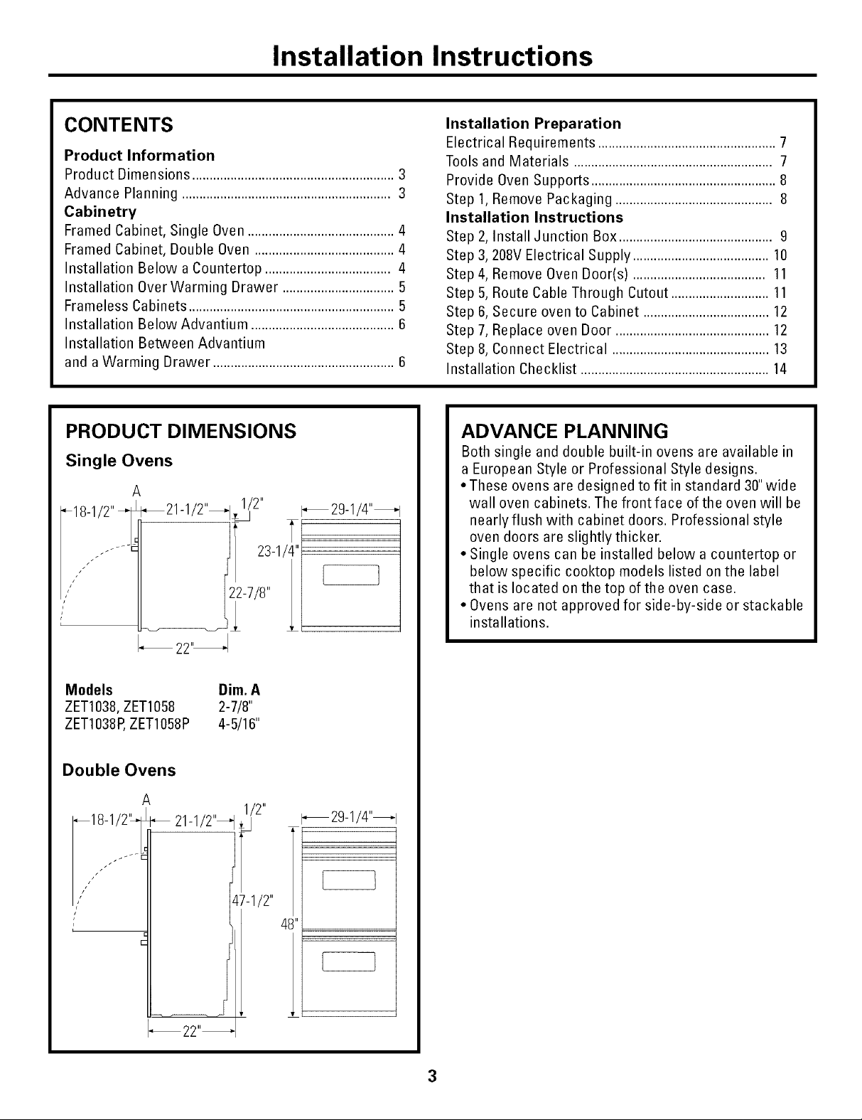
PRODUCT DIMENSIONS
Single Ovens
_29-1/4"_
L_ 21-1/2"_,_/2''
18-1/2"
i
Installation Preparation
Electrical Requirements ...................................................7
Tools and Materials .........................................................7
Provide Oven Supports .....................................................8
Step 1,Remove Packaging ............................................. 8
Installation Instructions
Step 2, Install Junction Box ............................................ 9
Step 3, 208V Electrical Supply ....................................... 10
Step 4, Remove Oven Door(s) ...................................... 11
Step 5, Route Cable Through Cutout ............................ 11
Step 6, Secure oven to Cabinet ....................................12
Step 7, Replace oven Door ............................................12
Step 8, Connect Electrical .............................................13
Installation Checklist ......................................................14
ADVANCE PLANNING
Both single and double built-in ovens are available in
a European Style or Professional Style designs.
• These ovens are designed to fit in standard 30"wide
wall oven cabinets. The front face of the oven will be
nearly flush with cabinet doors. Professional style
oven doors are slightly thicker.
• Single ovens can be installed below a countertop or
below specific cooktop models listed on the label
that is located on the top of the oven case.
• Ovens are not approved for side-by-side or stackable
installations.
Models Dim. A
ZET1038,ZET1058 2-7/8"
ZET1038P,ZET1058P 4-5/16"
Double Ovens
A
_18-1/2" _t_ 21-1/2''4
/
_22"_
_29-1/4"_
4_
3
Page 4
Cabinetry
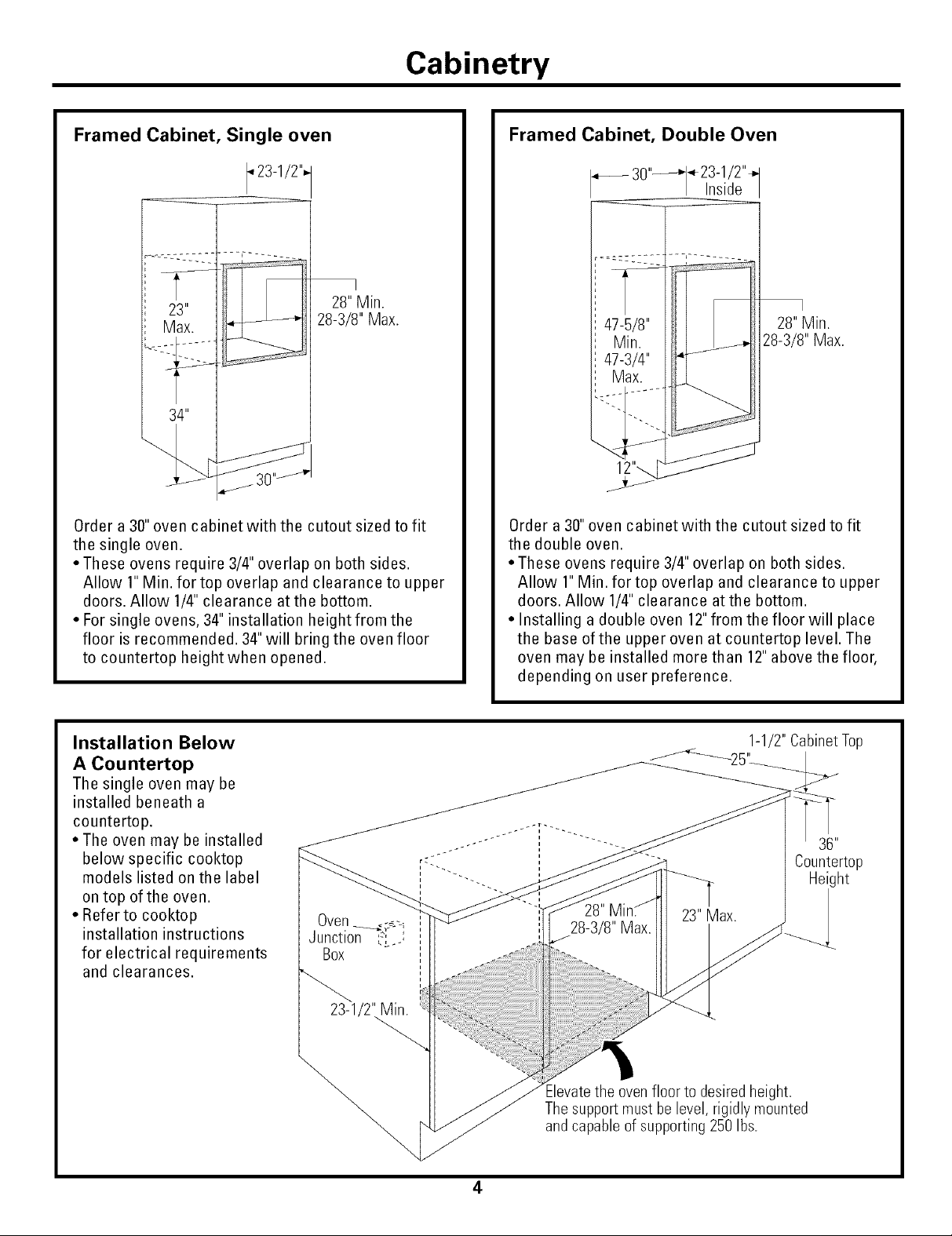
Framed Cabinet, Single oven
I23-1/2",
I
28" Min.
28-3/8" Max.
30
Order a 30" oven cabinet with the cutout sized to fit
the single oven.
• These ovens require 3/4" overlap on both sides.
Allow 1" Min. for top overlap and clearance to upper
doors. Allow 1/4" clearance atthe bottom.
• For single ovens, 34" installation height from the
floor is recommended. 34" will bring the oven floor
to countertop heightwhen opened.
Framed Cabinet, Double Oven
___ 30"_23-1/2"_
ns de
I
28"Min.
28-3/8"Max.
Order a 30" oven cabinet with the cutout sized to fit
the double oven.
• These ovens require 3/4" overlap on both sides.
Allow 1" Min. for top overlap and clearance to upper
doors. Allow 1/4" clearance atthe bottom.
• Installing a double oven 12"from the floor will place
the base of the upper oven at countertop level. The
oven may be installed more than 12" above the floor,
depending on user preference.
Installation Below
A Countertop
The single oven may be
installed beneath a
countertop,
• The oven may be installed
below specific cooktop
models listed on the label
on top of the oven.
• Refer to cooktop
installation instructions
for electrical requirements
and clearances,
1-1/2" Cabinet Top
38"
Countertop
Height
23-1/2' Min.
Elevatethe oven floor to desiredheight.
Thesupportmust be level, rigidly mounted
and capable of supporting 250 Ibs.
4
Page 5
Cabinetry
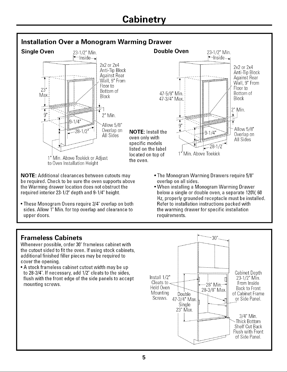
Installation Over a Monogram Warming Drawer
Single Oven
2x2or 2x4
Anti-Tip Block
Against Rear
,Wall, 9" From
Floorto
Bottom of
Block
_AIIow 5/8"
Overlap on
All Sides
1" Min. AboveToekickor Adjust
to OvenInstallation Height
NOTE: Additional clearances between cutouts may
be required. Check to be sure the oven supports above
the Warming drawer location does not obstruct the
required interior 23-1/2" depth and 9-1/4" height.
• These Monogram Ovens require 3/4" overlap on both
sides. Allow 1" Min. for top overlap and clearance to
upper doors.
NOTE: Install the
oven only with
specific models
listed on the label
located on top of
the oven.
Double Oven
,,
23-1/2" Min.
2x2 or 2x4
Anti-Tip Block
Against Rear
Wall, 9" From
Floorto
Bottom of
Block
5/8"
L,,,,, All Sides
AboveToekick
• The Monogram Warming Drawers require 5/8"
overlap on all sides.
• When installing a Monogram Warming Drawer
below a single or double oven, a separate 120V,60
Hz, properly grounded receptacle must be installed.
Refer to installation instructions packed with
the warming drawer for specific installation
requirements.
Overlapon
Frameless Cabinets
Whenever possible, order 30" frameless cabinet with
the cutout sided to fit the oven. If using stock cabinets,
additional finished filler pieces may be required to
cover the opening.
• A stock frameless cabinet cutout width may be up
to 28-3/4". If necessary, add 1/2" cleats to the sides,
flush with the front edge of the side panels to accept
mounting screws.
Install 1/2"
Cleatsto
Hold
Mounting
5
Screws.
Double
47-3/4" Max
Single
23" Max.
Cabinet Depth
23-1/2" Min.
FromInside
Backto Front
of Cabinet Frame
or Side Panel.
3/4" Min.
_Thick Bottom
Shelf Cut Back
Flushwith Front
of Side Panel.
Page 6

Cabinetry
Installation Below a
Monogram Advantium Oven
23-1/2" Min.
_-Inside_.
2" Min.
Installation Between a
Monogram Advantium Oven and
a Warming Drawer
Note: Install the
oven only with
specific models
listed on the label
located on top of
the oven.
45-1/4"
NOTE: The middle rail separating the two openings
may need to be larger than the 2" minimum shown.
Always refer to the individual installation instructions
packed with each product for specific requirements.
Combined Advantium and Wall Oven
Installation:
When installed in combination with a Monogram single
wall oven, use separate electrical junction boxes,
OR,
Install a single junction box connected to 50 amp supply
circuit or properly rated supply circuit.
• Refer to the Advantium oven installation instructions
for electrical requirements of that product.
• These connections must be made by a qualified
electrician. All electrical connections must meet
National Electrical code or prevailing local codes.
Warming Drawer Combined with Advantium
and Single Oven:
Install a separate 120V,60Hz, properly grounded
receptacle. See installation Instructions packed with
the Warming Drawer.
NOTE: Additional clearances may be required.
Check to be sure the oven supports above the
Warming Drawer does not obstruct the required
interior 23-1/2" depth and 9-1/4" height. The middle rail
separating the openings may need to be larger than
the 2" minimum shown. Always refer to the individual
installation instructions packed with each product for
specific requirements.
6
Page 7

Installation Preparation
ELECTRICAL REQUIREMENTS
These Monogram built-in ovens require a separate
properly ground ed 3-wire 120/208 or 120/240 volt,
60 Hz power supply, protected by a time delay fuse or
circuit breaker.
• Double ovens are rated at 6.5 KW at 240 volt and
6.5 KW at 208 volt.
• Single ovens are rated at 3.3 KW at 240volt and
2.8 KW at 208 volt.
• Ovens are supplied with a flexible power cable
which must be attached to a junction box. The cable
length is 53"for both single and double convection
ovens.
• DO NOT use an extension cord with these
appliances.
• DO NOT shorten the flexible power cable.
We recommend thatthe electrical wiring and hookup
of your oven be performed by a qualified electrician.
After installation, have the electrician show you
where your main oven disconnect is located.
Check with local utilities for electrical codes which
apply in your area. Failure to wire the oven according
to governing codes could result in a hazardous
condition. If there are no local codes, the oven must
be wired and fused in accordance with Nation
Electrical Code, ANSl/NFPA No. 70-latest edition.
You can get a copy by writing:
National Fire Protection Association
Batterymarch Park
Quincy MA 02269
TOOLS AND MATERIALS
YOU WILL NEED
• 2 X 4 Lumber for runners or 3/4" thick shelving
• Saw
•Level
• Phillips screwdriver, wood screws and adhesive
or other hardware for installing runners or shelf to
support the oven.
*Wire cutters and wire stripper
• Junction box
• Electrical cable - 3-conductor or 4-concuctor wire,
as required by local codes.
• UL listed conduit connector
The National Electrical Code requires that new,
but not existing construction utilize a four-conductor
connection to an electric oven. When installing an
electric oven in new construction, a mobile home,
recreational vehicle or an area where local codes
prohibit grounding through the neutral conductor,
follow instructions in the section on NEW
CONSTRUCTION AND FOUR-CONDUCTOR
BRANCH CIRCUIT CONNECTION.
Page 8

Installation Preparation
PROVIDE OVEN SUPPORTS
Ovens may be supported by either a solid bottom or
by 2x 4 runners.
• The support must be level and rigidly mounted,
flush with the bottom edge of the cutout.
_/_ 2"x 4" or
Equivalent Runners
/x \\ ;
F \ :
24"
i
_25_
30"
• Interior nter or
3/4 Mm. Cabinet Cabinet )
Sheeting (Plywood _-Width_l _ n_nm_, /
orWafer Board __
Sourcedon Site) _Jf
h<-- _'-_-._ Heigh.t ,
,, _,,_ II _ as Hequlreu
3/4 Sheetin_g _.__"_ _
(PlywoodorWafer _ -_
BoardSourced
on Site)
1
1
1
1
1
1
1
1
i
Levelwith Bottom
Edgeof Cutout and Flush
with Cabinet Front
ISTEP 1] REMOVE PACKAGING
• Remove the carton, plastic coverings and styrofoam
side/corner posts.
• To prevent damage to the floor, do not remove the
styrofoam base until the oven is ready to be installed.
• Remove oven contents, shelves and packaging.
• Be sure to remove protective tape from the door
latch pin.
l/l
RemoveTape
FromLatch Pin
If a solid bottom is used:
• Cut two pieces of 3/4" thick sheeting to fit inside
cabinet depth and available inside cabinet height.
If there is no interference below the cutout, such as
drawer runners, the sheeting can rest on the floor.
Secure the sheeting strips or pieces to the cabinet
walls with screws. Lay 2 x 4 or solid bottom on top
of the sheeting and drive screws through the top
and into the sheeting.
• The entire weight of the oven is supported by
2x4 runners or solid floor and must be capable of
supporting 350 Ibs. For double ovens and 250 Ibs.
For single ovens.
8
Page 9

Installation Preparation
WARNING
ELECTRICAL SHOCK HAZARD
• The electrical power to the oven
branch circuit must be shut-off
while line connections are being
made.
• Use copper wiring only.
• Electrical ground is required on this appliance. The
free end of the green wire (the ground wire) must be
connected to a suitable ground. This wire must
remain grounded to the oven.
ADVERTISSEMENT
RISQUE DE CHOC I_LECTRIQUE
• Le circuit d'alimentation du four
doit _tre hors tension pendant le
branchement.
• Utiliser uniquement des fils en
cuivre.
• Cet appareil doit _tre mis _ la terre. L'extr_mit_ du
fil vert (le fil de mise _ la terre) doit _tre branch_e
une terre appropri_e. Ce fil doit rester branch_
au four.
• If a cold water pipe is interrupted by plastic,
non-metallic gaskets, union connections or other
insulating materials, DO NOT use for grounding.
• DO NOT ground to a gas pipe.
• DO NOT have a fuse in the NEUTRAL or GROUNDING
circuit. A fuse in the NEUTRAL or GROUNDING circuit
could result in an electrical shock.
• Check with a qualified electrician if you are in doubt
as to whether the appliance is properly grounded.
Failure to follow these instructions could result in
serious injury or death.
• NE PAS utiliser pour la mise _ laterre un tuyau d'eau
froide interrompu par du plastique, des joints ou des
raccords non-m_talliques, ou autre materiel isolant.
• NE PAS mettre _ la terre sur un tuyau de gaz.
• NE PAS utiliser de fusible sur le circuit de NEUTRE
ou de MISE _,LA TERRE.Unfusible dans le circuit
de NEUTREou de MISE _,LATERRE peut causer
un choc _lectrique.
• En cas de doute, faire v_rifier la mise _ la terre de
I'appareil par un _lectricien qualifi&
II faut suivre ces instructions pour _viter des blessures
graves ou la mort.
[STEP 21 INSTALL JUNCTION BOX
The conduit is located in the center at the top rear of
the oven.
• Locate and install the junction box within reach of
the power cable.
• Install the junction box in an adjacent left or right
cabinet, below the cutout floor, or in the top cabinet
above the cutout.
9
Page 10

Installation Instructions
[STEP 31 208V ELECTRICAL SUPPLY
WARNING
These ovens are pre-wired for connection to 240 volt,
60 HZ, supply. If connecting to a 208volt supply,
modifications must be made.
AVERTISSEMENT
Oes fours sont c_bl_s pour branchement sur
une alimentation en 240 V, 60 Hz. II faut faire des
modifications en cas de branchement sur une
alimentation en 208 V.
SKIP THIS STEP IF YOU ARE CONNECTING
TO 240 VOLT POWER SUPPLY.
If connecting to a 208 volt, 60 HZ supply, a jumper
must be used across two terminals.
• For double ovens, there are two jumpers, one for the
upper oven, one for the lower oven.
• For single ovens there is one jumper.
To connectto 208V circuit:
• Remove the access panel(s) located on the back of
the ovens.
• Loosen the first and second screws in the terminal
block as shown.
FOR LOWER OVEN ON DOUBLE OVENS
o
LoosenScrewsf
o
• Loosen the first and second screws in the terminal
block as shown.
• Remove the jumper and place between the first and
second screws, tighten the screws to hold the
jumper.
• Replace the access panel(s).
Jumper
Jumper Tighten Screws
• Remove the jumper and place between the first and
second screws, tighten the screws to hold the jumper.
10
Page 11

Installation Instructions
ISTEP41REMOVE OVEN DOOR(S)
• Open the door fully.
• Pull the hinge latches up and hook them onto the
hinge hooks on both sides,
Hinge Latch
in the Hooked
Position for
Removal
• Close the door about halfway, orto a 45° opening.
Pull the door straight off and away from the oven,
ISTEP 51 ROUTE CABLE THROUGH
CUTOUT
CAUTION
Oven(s) are very heavy. 2 people are required to lift
oven(s) into the opening, Ovens have side handles,
Grasp side handle with one hand and put other hand
into the oven opening, Carefully, lift the oven to the
cabinet opening,
PRUDENCE
Le four est Iourd, II faut deux personnes pour soulever
et mettre le four dans I'ouverture, Le four est _quip_
de poign_es lat_rales, Prendre la poign_e lat_rale
d'une main et mettre I'autre main dans I'ouverture du
four. Soulever le four avec precaution et le mettre
dans I'ouverture de I'armoire de cuisine,
RemovalPosition
• Laythe oven door on packaging to prevent
scratching.
Upper
HingeArm
Hinge Arm
CAUTION
Do not lift the oven or oven door with handle.
PRUDENCE
Ne pas lever le four ou la porte du four par la poign_e,
/rofoam
Shipping Base
With oven in front of cabinet opening:
• Insert power cable into cabinet opening.
• Lift the oven into the opening while continuing to feed
the cable in the direction of the installed junction box.
Be sure the cable does not get pinched between the
back of the oven and cabinet wall,
11
Page 12

Installation Instructions
ISTEP61SECURE OVEN TO
CABINET
• Slide oven into cabinet opening.
• Drill 3/32" pilot holes through the oven front frame
and into the cabinet frame.
QQ QQQ
/ \
• Secure oven to cabinet with screws provided. Single
ovens use 2 screws, one on each side. Double ovens
use 4screws, 2on each side.
WARNING
Securely fasten oven to cabinet using the screws
provided. Failure to do so could cause the oven to
move ortip during use and result in personal injury.
[STEP 7] REPLACE OVEN DOOR
• Grasp door firmly on both sides.
• Insert and seatthe upper and lower hinge arms into
the oven slots.
• Align the groove on the lower hinge arm with the
bottom of the oven slot.
Slot
HingeLatch--
Un-Hookedafter
Replacement
• Open the door fully and push hinge latches down,
as illustrated, on both sides to release the lower
hinge arm.
• Close the door and open slowly to be sure it moves
smoothly.
AVERTISSEMENT
Monter fermement le four sur I'armoire de
cuisine avec les vis fournies. Si le four n'est pas
mont_ fermement, il peut se d@lacer ou basculer
pendant I'usage et causer des blessures.
12
Page 13

Installation Instructions
ISTEP81CONNECT ELECTRICAL
WARNING
ELECTRICAL SHOCK HAZARD
• Electrical ground is required on
this appliance.
• DO NOT connect to the
electrical supply until appliance
is permanently grounded.
• Disconnect power to the junction box before
making the electrical connection,
• This appliance must be connected to a grounded,
metallic, permanent wiring system or a grounding
connector should be connected to the grounding
terminal or wire lead on the appliance.
Failure to do so could result in fire, personal injury or
electrical shock,
3-Conductor Branch Circuit
Branch Circuit Oven
Red Red
120VAC (_
AVERTISSEMENT
RISQUE DE CHOC
I_LECTRIQUE
• Cet appareil dolt _tre mis _ la terre.
• NE PAS brancher
I'alimentation _lectrique si
I'appareil n'est pas mis _ la
terre de fa£on permanente.
• D_brancher I'alimentation au boftier de
raccordement avant de faire le branchement
_lectrique.
• Cet appareil dolt _tre branch_ sur un circuit
permanent m_tallique _ la terre ou un connecteur
de mise _la terre dolt _tre branch_ _ la borne de
mise _ la terre ou un fil de I'appareil.
II faut suivre ces instructions pour @iter des
incendies, des blessures graves ou la mort.
4-Conductor Branch Circuit
Branch Circuit Oven
Red Red
120VAC {[}{]}
White or
Neutral Gray CO Green
I White
120VAC Black _ Black
When connecting to a 3-conductor branch
circuit:
• Connect oven red lead to branch circuit red lead.
• Connect oven black lead to branch circuit black
lead.
• Connect oven bare copper conductor and white lead
to branch circuit neutral lead (white or gray),
120VAC
GND (_
Neutral Gray
When connecting to a 4-conductor branch
circuit:
• Connect oven red lead to branch circuit red lead.
• Connect oven black lead to branch circuit black lead,
• Break connection between oven white lead and oven
bare copper conductor.
• Connect oven white lead to branch circuit neutral
lead (white or gray).
• Connect oven bare copper conductor to branch
circuit ground lead (green or bare copper).
NOTE: Use copper wire only.
Black Black
Bareor
Green Green
White or
White
13
Page 14

Installation Instructions
INSTALLATION CHECKLIST
1.Turn all knobs to OFFor Normal.
2.Turn on power atthe circuit breaker.
3. Set the clock for current time of day. Refer to the
Owner's Manual for instructions.
4. Check oven door for full opening and closing,
Oven lights should be on when the door is opened
and off when the door is closed.
14
Page 15

Notes
15
Page 16

IPub.No.49-80295]
01-05JR
PrintedinItaly
NOTE:While performing installations described in this book,
safety glasses or goggles should beworn.
l_or ,\lo_tog'ram 1o(<11s_'n,_ce _n 3ore an, a, (:<111
1.800.444. 1641.
NOTE: Product improvcmcm is a c(mtinuing ( n(Icavor
al General Electric. Therefore, materials, appearmace
and Sl)((ifi(ations are sll|)je(I t() (ilang( _,_+illlollt noli(e.
Monogram;
GEConsumer & Industrial
Louisville, KY40225
©2005 GE Company
 Loading...