

Page 1
Installation
30” (76.2 cm) Built-In
Wall Oven
Instructions
If you have questions, call 1.800.GE.CARES or visit our website at:
ge.com
ZET1, ZET2
Before You Begin
Read these instructions carefully and completely.
• IMPORTANT—Save these
instructions for local inspector’s use.
• IMPORTANT—Observe all
governing codes and ordinances.
• Note to Installer—Be sure to leave these
instructions with the consumer.
• Note to Consumer—Keep these
instructions for future reference.
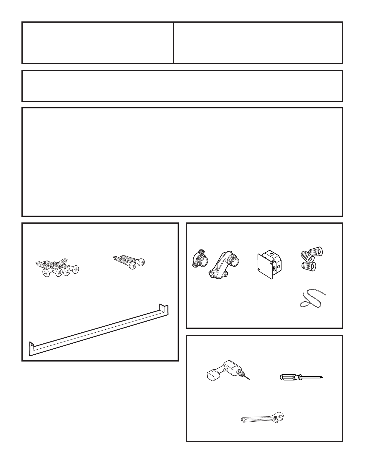
Parts Included
(Appearance may vary.)
5/8” Wood
3/4” Wood
Screws
(8-18 x .750 flat-head
Phillips wood screws)
(8A8 x .625 truss-head
Phillips wood screws)
Screws
• Proper installation is the responsibility
of the installer and product failure due
to improper installation is NOT covered
under warranty.
• NOTE—This appliance must be properly
grounded.
• ATTENTION INSTALLER
All electric wall ovens must be hard wired
(direct wired) into an approved junction
box. A plug and receptacle is NOT permitted
on these products.
Materials Needed
Wire Nuts
Strain Relief Clamp
for 1/2” conduit
Junction
Box
31-10649-2 07-07 JR
Metal Bottom
Trim Assembly
Tools Needed
1/8” Drill Bit and
Electric or Hand Drill
Adjustable Wrench
1
36” (91 cm)
of String
Phillips
Screwdriver
Page 2
Installation Instructions
IMPORTANT SAFETY INSTRUCTIONS
For Your Safety
• Be sure your oven is installed properly by
a qualified installer or service technician.
• Make sure the cabinets and wall coverings
around the oven can withstand the
temperatures (up to 200°F [93.3°C])
generated by the oven.
• Be sure the oven is securely installed in a
cabinet that is firmly attached to the house
structure. Weight on the oven door could
cause the oven to tip and result in injury.
Never allow anyone to climb, sit, stand or
hang on the oven door.
WARNING:
power to the oven supply line
must be shut off while line
connections are being made. Failure
to do so could result in serious injury
or death.
The electrical
Electrical
Electrical
Requirements (cont.)
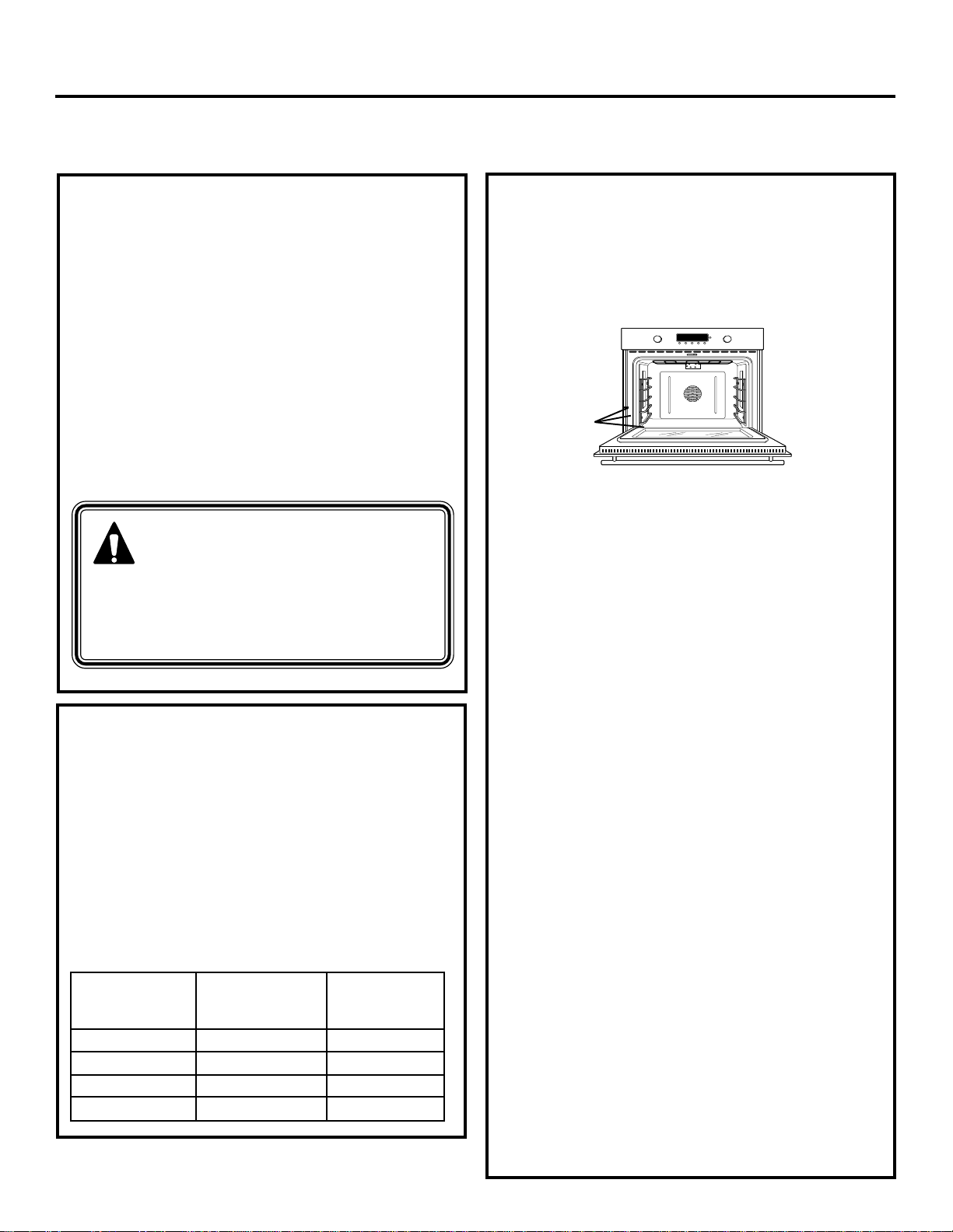
Rating plate is located on the oven side trim,
side front frame or lower front frame.
Rating Plate
Location
We recommend you have the electrical
wiring and hookup of your oven connected by a
qualified electrician. After installation, have the
electrician show you where your main oven
disconnect is located.
Check with your local utilities for electrical
codes which apply in your area. Failure to wire
your oven according to governing codes could
result in a hazardous condition. If there are no
local codes, your oven must be wired and fused
to meet the requirements of the National
Electrical Code, ANSI/NFPA No. 70–Latest
Edition. You can get a copy by writing:
Requirements
This appliance must be supplied with the
proper voltage and frequency and connected
to an individual, properly grounded branch
circuit, protected by a circuit breaker or fuse.
See the rating plate located on the oven frame
to determine the rating of the product. Use
the chart below to determine the minimum
recommended dedicated circuit protection.
Recommended
KW Rating KW Rating Circuit Size
240V 208V (Dedicated)
≤4.8 KW ≤4.1 KW 20 Amp
4.9 KW–7.2 KW 4.3 KW–6.2 KW 30 Amp
7.3 KW–9.6 KW 6.3 KW–8.3 KW 40 Amp
9.7 KW–12.0 KW 8.4 KW–10.4 KW 50 Amp
National Fire Protection Association
Batterymarch Park
Quincy, MA 02269
Effective January 1, 1996, the National
Electrical Code requires that new, but not
existing, construction utilize a four-conductor
connection to an electric oven. When installing
an electric oven in new construction, a mobile
home, recreational vehicle or an area where
local codes prohibit grounding through the
neutral conductor, follow the instructions in
the section on NEW CONSTRUCTION AND
FOUR-CONDUCTOR BRANCH CIRCUIT
CONNECTION.
You must use a three-wire, single-phase A.C.
208Y/120 Volt or 240/120 Volt, 60 hertz
electrical system. If you connect to aluminum
wiring, properly installed connectors approved
for use with aluminum wiring must be used.
2
Page 3
Installation Instructions
Pre-Installation Checklist
ALL INSTALLATION INFORMATION
ON THE FOLLOWING PAGES IS TO
BE USED FOR SINGLE AND DOUBLE
OVEN INSTALLATION!
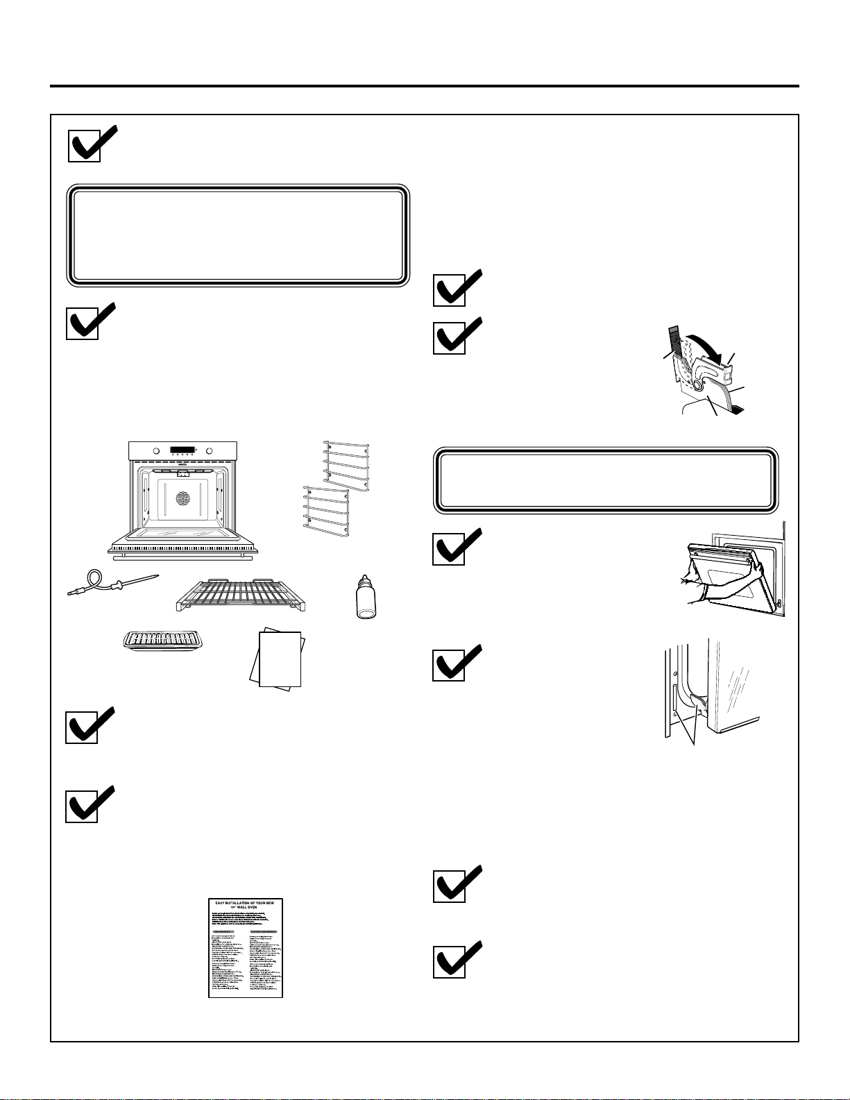
Remove packaging materials.
Check behind hinges and under
false bottom. Remove labels on the
outside of the door, plastic on trims
and panel, all tape around the oven,
and any shipping screws securing
the oven to the base pad.
Rack Supports
with Hex Nuts
Temperature
Probe
Broiler Pan
and Grid
Oven Racks
OWNER- Keep these instructions
OWNER- Keep these instructions
OWNER- Keep these instructions
for future reference.
for future reference.
for future reference.
Note- This appliance must be
Note- This appliance must be
Note- This appliance must be
Note- This appliance must be
properly grounded (if applicable).
properly grounded (if applicable).
properly grounded (if applicable).
properly grounded (if applicable).
Before you begin-Read these
Before you begin-Read these
Before you begin-Read these
Before you begin-Read these
instructions completely and
instructions completely and
instructions completely and
instructions completely and
carefully.
carefully.
carefully.
carefully.
IMPORTANT- Save these
IMPORTANT- Save these
IMPORTANT- Save these
IMPORTANT- Save these
instructions for local inspector’s use.
instructions for local inspector’s use.
instructions for local inspector’s use.
instructions for local inspector’s use.
IMPORTANT- OBSERVE ALL
IMPORTANT- OBSERVE ALL
IMPORTANT- OBSERVE ALL
IMPORTANT- OBSERVE ALL
GOVERNING CODES AND ORDIANCES.
GOVERNING CODES AND ORDIANCES.
GOVERNING CODES AND ORDIANCES.
GOVERNING CODES AND ORDIANCES.
Note to Installer- Be sure to leave
Note to Installer- Be sure to leave
Note to Installer- Be sure to leave
Note to Installer- Be sure to leave
these instructions with the consumer.
these instructions with the consumer.
these instructions with the consumer.
these instructions with the consumer.
OWNER- Keep these instructions
OWNER- Keep these instructions
OWNER- Keep these instructions
OWNER- Keep these instructions
for future reference.
for future reference.
for future reference.
for future reference.
Note- This appliance must be
Note- This appliance must be
Note- This appliance must be
Note- This appliance must be
properly grounded (if applicable).
properly grounded (if applicable).
properly grounded (if applicable).
properly grounded (if applicable).
EASY INSTALLATION OF YOUR NEW
EASY INSTALLATION OF YOUR NEW
Before you begin-Read these instructions completely and carefully.
Before you begin-Read these instructions completely and carefully.
Before you begin-Read these instructions completely and carefully.
Before you begin-Read these instructions completely and carefully.
Before you begin-Read these instructions completely and carefully.
Before you begin-Read these instructions completely and carefully.
Before you begin-Read these instructions completely and carefully.
Before you begin-Read these instructions completely and carefully.
Before you begin-Read these instructions completely and carefully.
Before you begin-Read these instructions completely and carefully.
Before you begin-Read these instructions completely and carefully.
Before you begin-Read these instructions completely and carefully.
IMPORTANT- Save these instructions for local inspector’s use.
IMPORTANT- Save these instructions for local inspector’s use.
IMPORTANT- Save these instructions for local inspector’s use.
IMPORTANT- Save these instructions for local inspector’s use.
IMPORTANT- Save these instructions for local inspector’s use.
IMPORTANT- Save these instructions for local inspector’s use.
IMPORTANT- Save these instructions for local inspector’s use.
IMPORTANT- Save these instructions for local inspector’s use.
IMPORTANT- Save these instructions for local inspector’s use.
IMPORTANT- Save these instructions for local inspector’s use.
IMPORTANT- Save these instructions for local inspector’s use.
IMPORTANT- Save these instructions for local inspector’s use.
30" WALL OVEN
IMPORTANT- OBSERVE ALL GOVERNING CODES AND ORDIANCES.
IMPORTANT- OBSERVE ALL GOVERNING CODES AND ORDIANCES.
IMPORTANT- OBSERVE ALL GOVERNING CODES AND ORDIANCES.
IMPORTANT- OBSERVE ALL GOVERNING CODES AND ORDIANCES.
IMPORTANT- OBSERVE ALL GOVERNING CODES AND ORDIANCES.
IMPORTANT- OBSERVE ALL GOVERNING CODES AND ORDIANCES.
IMPORTANT- OBSERVE ALL GOVERNING CODES AND ORDIANCES.
IMPORTANT- OBSERVE ALL GOVERNING CODES AND ORDIANCES.
IMPORTANT- OBSERVE ALL GOVERNING CODES AND ORDIANCES.
IMPORTANT- OBSERVE ALL GOVERNING CODES AND ORDIANCES.
IMPORTANT- OBSERVE ALL GOVERNING CODES AND ORDIANCES.
IMPORTANT- OBSERVE ALL GOVERNING CODES AND ORDIANCES.
Note to Installer- Be sure to leave these instructions with the consumer.
Note to Installer- Be sure to leave these instructions with the consumer.
Note to Installer- Be sure to leave these instructions with the consumer.
Note to Installer- Be sure to leave these instructions with the consumer.
Note to Installer- Be sure to leave these instructions with the consumer.
Note to Installer- Be sure to leave these instructions with the consumer.
Note to Installer- Be sure to leave these instructions with the consumer.
Note to Installer- Be sure to leave these instructions with the consumer.
Note to Installer- Be sure to leave these instructions with the consumer.
Note to Installer- Be sure to leave these instructions with the consumer.
Note to Installer- Be sure to leave these instructions with the consumer.
Note to Installer- Be sure to leave these instructions with the consumer.
OWNER- Keep these instructions for future reference.
OWNER- Keep these instructions for future reference.
OWNER- Keep these instructions for future reference.
OWNER- Keep these instructions for future reference.
OWNER- Keep these instructions for future reference.
OWNER- Keep these instructions for future reference.
OWNER- Keep these instructions for future reference.
OWNER- Keep these instructions for future reference.
OWNER- Keep these instructions for future reference.
OWNER- Keep these instructions for future reference.
OWNER- Keep these instructions for future reference.
OWNER- Keep these instructions for future reference.
Before you begin-Read these instructions completely and carefully.
Before you begin-Read these instructions completely and carefully.
Before you begin-Read these instructions completely and carefully.
Before you begin-Read these instructions completely and carefully.
Before you begin-Read these instructions completely and carefully.
Before you begin-Read these instructions completely and carefully.
Before you begin-Read these instructions completely and carefully.
Before you begin-Read these instructions completely and carefully.
Before you begin-Read these instructions completely and carefully.
Before you begin-Read these instructions completely and carefully.
Before you begin-Read these instructions completely and carefully.
Before you begin-Read these instructions completely and carefully.
Note- This appliance must be properly grounded (if applicable).
Note- This appliance must be properly grounded (if applicable).
Note- This appliance must be properly grounded (if applicable).
Note- This appliance must be properly grounded (if applicable).
Note- This appliance must be properly grounded (if applicable).
Note- This appliance must be properly grounded (if applicable).
Note- This appliance must be properly grounded (if applicable).
Note- This appliance must be properly grounded (if applicable).
Note- This appliance must be properly grounded (if applicable).
Note- This appliance must be properly grounded (if applicable).
Note- This appliance must be properly grounded (if applicable).
Note- This appliance must be properly grounded (if applicable).
IMPORTANT- Save these instructions for local inspector’s use.
IMPORTANT- Save these instructions for local inspector’s use.
IMPORTANT- Save these instructions for local inspector’s use.
IMPORTANT- Save these instructions for local inspector’s use.
IMPORTANT- Save these instructions for local inspector’s use.
IMPORTANT- Save these instructions for local inspector’s use.
IMPORTANT- Save these instructions for local inspector’s use.
IMPORTANT- Save these instructions for local inspector’s use.
IMPORTANT- Save these instructions for local inspector’s use.
IMPORTANT- Save these instructions for local inspector’s use.
IMPORTANT- Save these instructions for local inspector’s use.
IMPORTANT- Save these instructions for local inspector’s use.
IMPORTANT- OBSERVE ALL GOVERNING CODES AND ORDIANCES.
IMPORTANT- OBSERVE ALL GOVERNING CODES AND ORDIANCES.
IMPORTANT- OBSERVE ALL GOVERNING CODES AND ORDIANCES.
IMPORTANT- OBSERVE ALL GOVERNING CODES AND ORDIANCES.
IMPORTANT- OBSERVE ALL GOVERNING CODES AND ORDIANCES.
IMPORTANT- OBSERVE ALL GOVERNING CODES AND ORDIANCES.
IMPORTANT- OBSERVE ALL GOVERNING CODES AND ORDIANCES.
IMPORTANT- OBSERVE ALL GOVERNING CODES AND ORDIANCES.
IMPORTANT- OBSERVE ALL GOVERNING CODES AND ORDIANCES.
IMPORTANT- OBSERVE ALL GOVERNING CODES AND ORDIANCES.
IMPORTANT- OBSERVE ALL GOVERNING CODES AND ORDIANCES.
IMPORTANT- OBSERVE ALL GOVERNING CODES AND ORDIANCES.
Note to Installer- Be sure to leave these instructions with the consumer.
Note to Installer- Be sure to leave these instructions with the consumer.
Note to Installer- Be sure to leave these instructions with the consumer.
Note to Installer- Be sure to leave these instructions with the consumer.
Note to Installer- Be sure to leave these instructions with the consumer.
Note to Installer- Be sure to leave these instructions with the consumer.
Note to Installer- Be sure to leave these instructions with the consumer.
Note to Installer- Be sure to leave these instructions with the consumer.
Note to Installer- Be sure to leave these instructions with the consumer.
Note to Installer- Be sure to leave these instructions with the consumer.
Note to Installer- Be sure to leave these instructions with the consumer.
Note to Installer- Be sure to leave these instructions with the consumer.
OWNER- Keep these instructions for future reference.
OWNER- Keep these instructions for future reference.
OWNER- Keep these instructions for future reference.
OWNER- Keep these instructions for future reference.
OWNER- Keep these instructions for future reference.
OWNER- Keep these instructions for future reference.
OWNER- Keep these instructions for future reference.
OWNER- Keep these instructions for future reference.
OWNER- Keep these instructions for future reference.
OWNER- Keep these instructions for future reference.
OWNER- Keep these instructions for future reference.
OWNER- Keep these instructions for future reference.
FOR YOUR SAFETY
FOR YOUR SAFETY
FOR YOUR SAFETY
FOR YOUR SAFETY
Note- This appliance must be properly grounded (if applicable).
Note- This appliance must be properly grounded (if applicable).
Note- This appliance must be properly grounded (if applicable).
Note- This appliance must be properly grounded (if applicable).
Note- This appliance must be properly grounded (if applicable).
Note- This appliance must be properly grounded (if applicable).
Note- This appliance must be properly grounded (if applicable).
Note- This appliance must be properly grounded (if applicable).
Note- This appliance must be properly grounded (if applicable).
Note- This appliance must be properly grounded (if applicable).
Note- This appliance must be properly grounded (if applicable).
Note- This appliance must be properly grounded (if applicable).
Before you begin-Read these
Before you begin-Read these
Before you begin-Read these
Before you begin-Read these
instructions completely and
instructions completely and
instructions completely and
instructions completely and
carefully.
carefully.
carefully.
carefully.
FOR YOUR SAFETY
FOR YOUR SAFETY
FOR YOUR SAFETY
FOR YOUR SAFETY
IMPORTANT- Save these
IMPORTANT- Save these
IMPORTANT- Save these
IMPORTANT- Save these
instructions for local inspector’s use.
instructions for local inspector’s use.
instructions for local inspector’s use.
instructions for local inspector’s use.
Before you begin-Read these
Before you begin-Read these
Before you begin-Read these
Before you begin-Read these
IMPORTANT- OBSERVE ALL
IMPORTANT- OBSERVE ALL
IMPORTANT- OBSERVE ALL
IMPORTANT- OBSERVE ALL
instructions completely and
instructions completely and
instructions completely and
instructions completely and
GOVERNING CODES AND ORDIANCES.
GOVERNING CODES AND ORDIANCES.
GOVERNING CODES AND ORDIANCES.
GOVERNING CODES AND ORDIANCES.
carefully.
carefully.
carefully.
carefully.
Note to Installer- Be sure to leave
Note to Installer- Be sure to leave
Note to Installer- Be sure to leave
Note to Installer- Be sure to leave
IMPORTANT- Save these
IMPORTANT- Save these
IMPORTANT- Save these
IMPORTANT- Save these
these instructions with the consumer.
these instructions with the consumer.
these instructions with the consumer.
these instructions with the consumer.
instructions for local inspector’s use.
instructions for local inspector’s use.
instructions for local inspector’s use.
instructions for local inspector’s use.
OWNER- Keep these instructions
IMPORTANT- OBSERVE ALL
IMPORTANT- OBSERVE ALL
IMPORTANT- OBSERVE ALL
IMPORTANT- OBSERVE ALL
for future reference.
GOVERNING CODES AND ORDIANCES.
GOVERNING CODES AND ORDIANCES.
GOVERNING CODES AND ORDIANCES.
GOVERNING CODES AND ORDIANCES.
Note to Installer- Be sure to leave
Note to Installer- Be sure to leave
Note to Installer- Be sure to leave
Note to Installer- Be sure to leave
these instructions with the consumer.
these instructions with the consumer.
these instructions with the consumer.
these instructions with the consumer.
OWNER- Keep these instructions
OWNER- Keep these instructions
OWNER- Keep these instructions
OWNER- Keep these instructions
for future reference.
for future reference.
for future reference.
for future reference.
Note- This appliance must be
Note- This appliance must be
Note- This appliance must be
Note- This appliance must be
properly grounded (if applicable).
properly grounded (if applicable).
properly grounded (if applicable).
properly grounded (if applicable).
Before you begin-Read these
Before you begin-Read these
Before you begin-Read these
Before you begin-Read these
instructions completely and
instructions completely and
instructions completely and
instructions completely and
carefully.
carefully.
carefully.
carefully.
IMPORTANT- Save these
IMPORTANT- Save these
IMPORTANT- Save these
IMPORTANT- Save these
instructions for local inspector’s use.
instructions for local inspector’s use.
instructions for local inspector’s use.
instructions for local inspector’s use.
IMPORTANT- OBSERVE ALL
IMPORTANT- OBSERVE ALL
IMPORTANT- OBSERVE ALL
IMPORTANT- OBSERVE ALL
IMPORTANT- OBSERVE ALL
IMPORTANT- OBSERVE ALL
IMPORTANT- OBSERVE ALL
GOVERNING CODES AND ORDIANCES.
GOVERNING CODES AND ORDIANCES.
GOVERNING CODES AND ORDIANCES.
GOVERNING CODES AND ORDIANCES.
GOVERNING CODES AND ORDIANCES.
GOVERNING CODES AND ORDIANCES.
GOVERNING CODES AND ORDIANCES.
Note to Installer- Be sure to leave
Note to Installer- Be sure to leave
Note to Installer- Be sure to leave
Note to Installer- Be sure to leave
Note to Installer- Be sure to leave
Note to Installer- Be sure to leave
Note to Installer- Be sure to leave
Note to Installer- Be sure to leave
these instructions with the consumer.
these instructions with the consumer.
these instructions with the consumer.
these instructions with the consumer.
these instructions with the consumer.
these instructions with the consumer.
these instructions with the consumer.
these instructions with the consumer.
OWNER- Keep these instructions
OWNER- Keep these instructions
OWNER- Keep these instructions
OWNER- Keep these instructions
OWNER- Keep these instructions
OWNER- Keep these instructions
OWNER- Keep these instructions
OWNER- Keep these instructions
for future reference.
for future reference.
for future reference.
for future reference.
for future reference.
for future reference.
for future reference.
for future reference.
Note- This appliance must be
Note- This appliance must be
Note- This appliance must be
Note- This appliance must be
Note- This appliance must be
Note- This appliance must be
Note- This appliance must be
Note- This appliance must be
properly grounded (if applicable).
properly grounded (if applicable).
properly grounded (if applicable).
properly grounded (if applicable).
properly grounded (if applicable).
properly grounded (if applicable).
properly grounded (if applicable).
properly grounded (if applicable).
30" WALL OVEN
Before you begin-Read these
Before you begin-Read these
Before you begin-Read these
Before you begin-Read these
instructions completely and
instructions completely and
instructions completely and
instructions completely and
carefully.
carefully.
carefully.
carefully.
IMPORTANT- Save these
IMPORTANT- Save these
IMPORTANT- Save these
IMPORTANT- Save these
instructions for local inspector’s use.
instructions for local inspector’s use.
instructions for local inspector’s use.
instructions for local inspector’s use.
IMPORTANT- OBSERVE ALL
IMPORTANT- OBSERVE ALL
IMPORTANT- OBSERVE ALL
IMPORTANT- OBSERVE ALL
GOVERNING CODES AND ORDIANCES.
GOVERNING CODES AND ORDIANCES.
GOVERNING CODES AND ORDIANCES.
GOVERNING CODES AND ORDIANCES.
Note to Installer- Be sure to leave
Note to Installer- Be sure to leave
Note to Installer- Be sure to leave
Note to Installer- Be sure to leave
these instructions with the consumer.
these instructions with the consumer.
these instructions with the consumer.
these instructions with the consumer.
OWNER- Keep these instructions
OWNER- Keep these instructions
OWNER- Keep these instructions
OWNER- Keep these instructions
for future reference.
for future reference.
for future reference.
for future reference.
Note- This appliance must be
Note- This appliance must be
Note- This appliance must be
Note- This appliance must be
properly grounded (if applicable).
properly grounded (if applicable).
properly grounded (if applicable).
properly grounded (if applicable).
Before you begin-Read these
Before you begin-Read these
Before you begin-Read these
Before you begin-Read these
instructions completely and
instructions completely and
instructions completely and
instructions completely and
carefully.
carefully.
carefully.
carefully.
IMPORTANT- Save these
IMPORTANT- Save these
IMPORTANT- Save these
IMPORTANT- Save these
instructions for local inspector’s use.
instructions for local inspector’s use.
instructions for local inspector’s use.
instructions for local inspector’s use.
IMPORTANT- OBSERVE ALL
GOVERNING CODES AND ORDIANCES.
ELECTRICAL REQUIREMENTS
ELECTRICAL REQUIREMENTS
ELECTRICAL REQUIREMENTS
ELECTRICAL REQUIREMENTS
ELECTRICAL REQUIREMENTS
ELECTRICAL REQUIREMENTS
ELECTRICAL REQUIREMENTS
ELECTRICAL REQUIREMENTS
Before you begin-Read these
Before you begin-Read these
Before you begin-Read these
Before you begin-Read these
instructions completely and
instructions completely and
instructions completely and
instructions completely and
carefully.
carefully.
carefully.
carefully.
IMPORTANT- Save these
IMPORTANT- Save these
IMPORTANT- Save these
IMPORTANT- Save these
instructions for local inspector’s use.
instructions for local inspector’s use.
instructions for local inspector’s use.
instructions for local inspector’s use.
IMPORTANT- OBSERVE ALL
IMPORTANT- OBSERVE ALL
IMPORTANT- OBSERVE ALL
IMPORTANT- OBSERVE ALL
GOVERNING CODES AND ORDIANCES.
GOVERNING CODES AND ORDIANCES.
GOVERNING CODES AND ORDIANCES.
GOVERNING CODES AND ORDIANCES.
Note to Installer- Be sure to leave
Note to Installer- Be sure to leave
Note to Installer- Be sure to leave
Note to Installer- Be sure to leave
these instructions with the consumer.
these instructions with the consumer.
these instructions with the consumer.
these instructions with the consumer.
OWNER- Keep these instructions
OWNER- Keep these instructions
OWNER- Keep these instructions
OWNER- Keep these instructions
for future reference.
for future reference.
for future reference.
for future reference.
Note- This appliance must be
Note- This appliance must be
Note- This appliance must be
Note- This appliance must be
properly grounded (if applicable).
properly grounded (if applicable).
properly grounded (if applicable).
properly grounded (if applicable).
Before you begin-Read these
Before you begin-Read these
Before you begin-Read these
Before you begin-Read these
instructions completely and
instructions completely and
instructions completely and
instructions completely and
carefully.
carefully.
carefully.
carefully.
IMPORTANT- Save these
IMPORTANT- Save these
IMPORTANT- Save these
IMPORTANT- Save these
instructions for local inspector’s use.
instructions for local inspector’s use.
instructions for local inspector’s use.
instructions for local inspector’s use.
IMPORTANT- OBSERVE ALL
IMPORTANT- OBSERVE ALL
IMPORTANT- OBSERVE ALL
IMPORTANT- OBSERVE ALL
GOVERNING CODES AND ORDIANCES.
GOVERNING CODES AND ORDIANCES.
GOVERNING CODES AND ORDIANCES.
GOVERNING CODES AND ORDIANCES.
Note to Installer- Be sure to leave
Note to Installer- Be sure to leave
Note to Installer- Be sure to leave
Note to Installer- Be sure to leave
these instructions with the consumer.
these instructions with the consumer.
these instructions with the consumer.
these instructions with the consumer.
OWNER- Keep these instructions
OWNER- Keep these instructions
OWNER- Keep these instructions
OWNER- Keep these instructions
for future reference.
for future reference.
for future reference.
for future reference.
Note- This appliance must be
Note- This appliance must be
Note- This appliance must be
Note- This appliance must be
properly grounded (if applicable).
properly grounded (if applicable).
properly grounded (if applicable).
properly grounded (if applicable).
Graphite
Lubricant
Literature
Pack
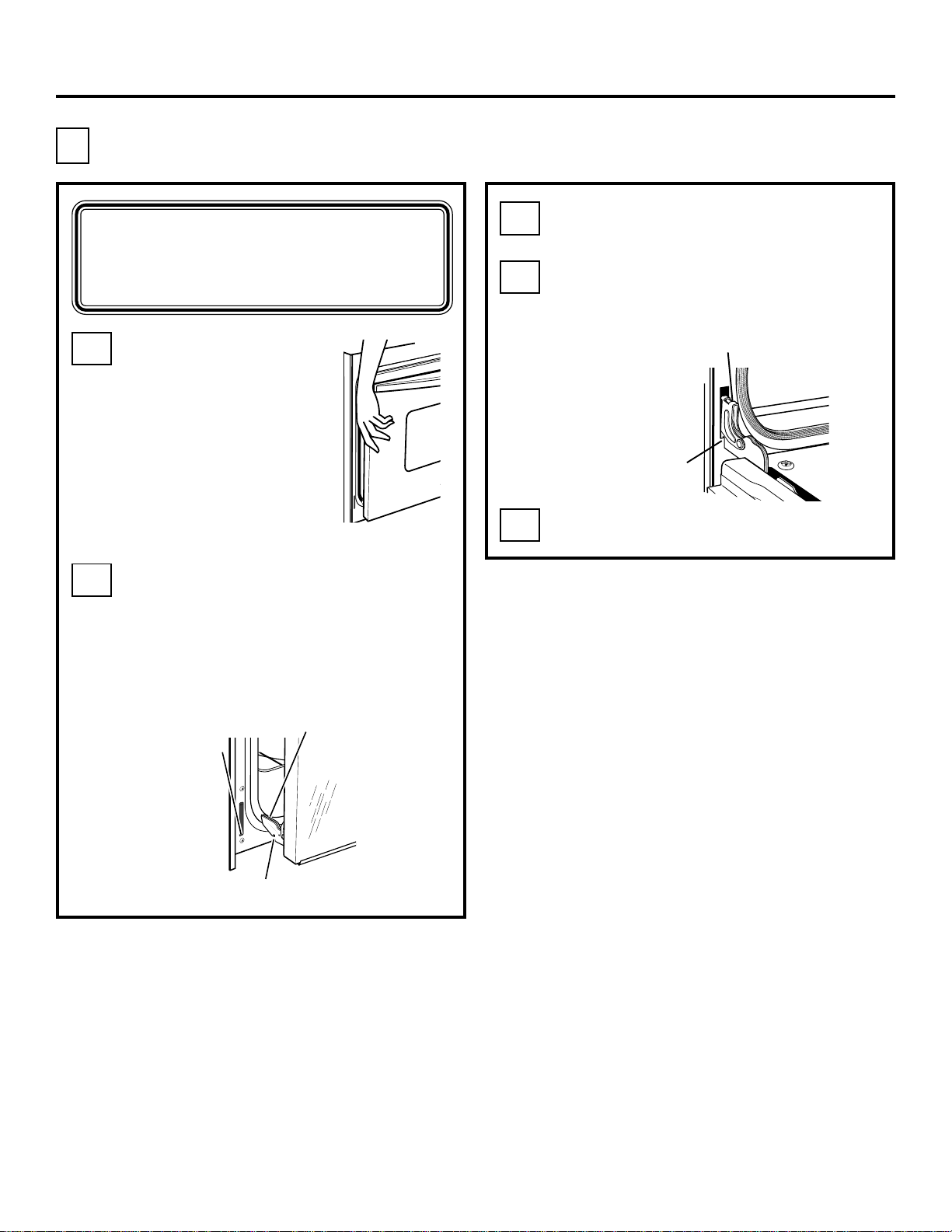
To Remove the Door (if necessary)
Door removal is not a requirement for
installation of the product, but is an
added convenience. To remove the door:
Open the oven door as far as it will go.
Hinge
Hinge
Hinge
Arm
Arm
Hinge
Unlocked
Unlocked
Position
Position
Push both hinge
locks down toward
the door frame,
to the unlocked
Hinge
Hinge
Slot
Slot
position. This may
require a flat-blade
screwdriver.
DO NOT LIFT THE DOOR
BY THE HANDLE!
Place hands on both sides
of the door, and close the
oven door to the removal
position, which is most of
the way closed.
Lift door up and out
until the hinge arms
clear the slots.
Removal Position
Open oven door and remove
literature pack, broiler pan and grid,
oven racks, rack supports and a bag
with 9 hex nuts.
Read Installation Instructions carefully
before you begin.
Be sure to place all literature, Owner’s
Manual, Installations, etc., in a safe
place for future reference.
Hinge Clears Slot
NOTE: The oven door is very heavy. Be sure
you have a firm grip before lifting the oven
door off the hinges. Use caution once the
door is removed. Do not lay the door on its
handle. This could cause dents or scratches.
Place the oven on a table or platform
even with the cutout opening. (Platform
must support 175 lbs. [79 kg] single,
350 lbs. [159 kg] double.)
Remove the bottom trim from the top
of the oven. It will be installed at the
end of the installation process. The
trim is wrapped separately and taped
to the top of the unit.
3
Page 4
Installation Instructions
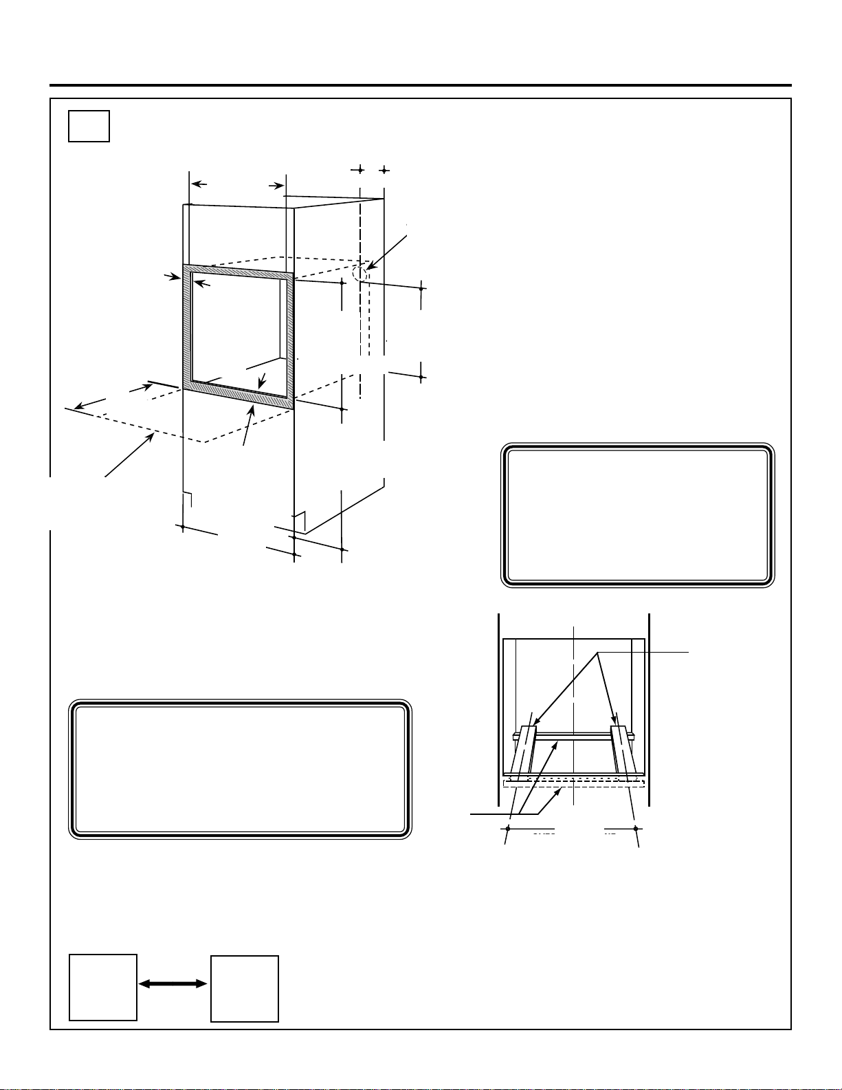
A1
ALLOW 11/16" FOR
OVERLAP OF THE
OVEN OVER SIDE
EDGES OF CUTOUT
ALLOW A MINIMUM
Allow a minimum
OF 21" FOR CLEARANCE
of 21” (53.3 cm) for
TO ADJACENT CORNERS,
clearance to adjacent
DRAWERS, WALLS ETC.
WHEN THE DOOR IS OPENED.
corners, drawers,
walls, etc. when
door is open
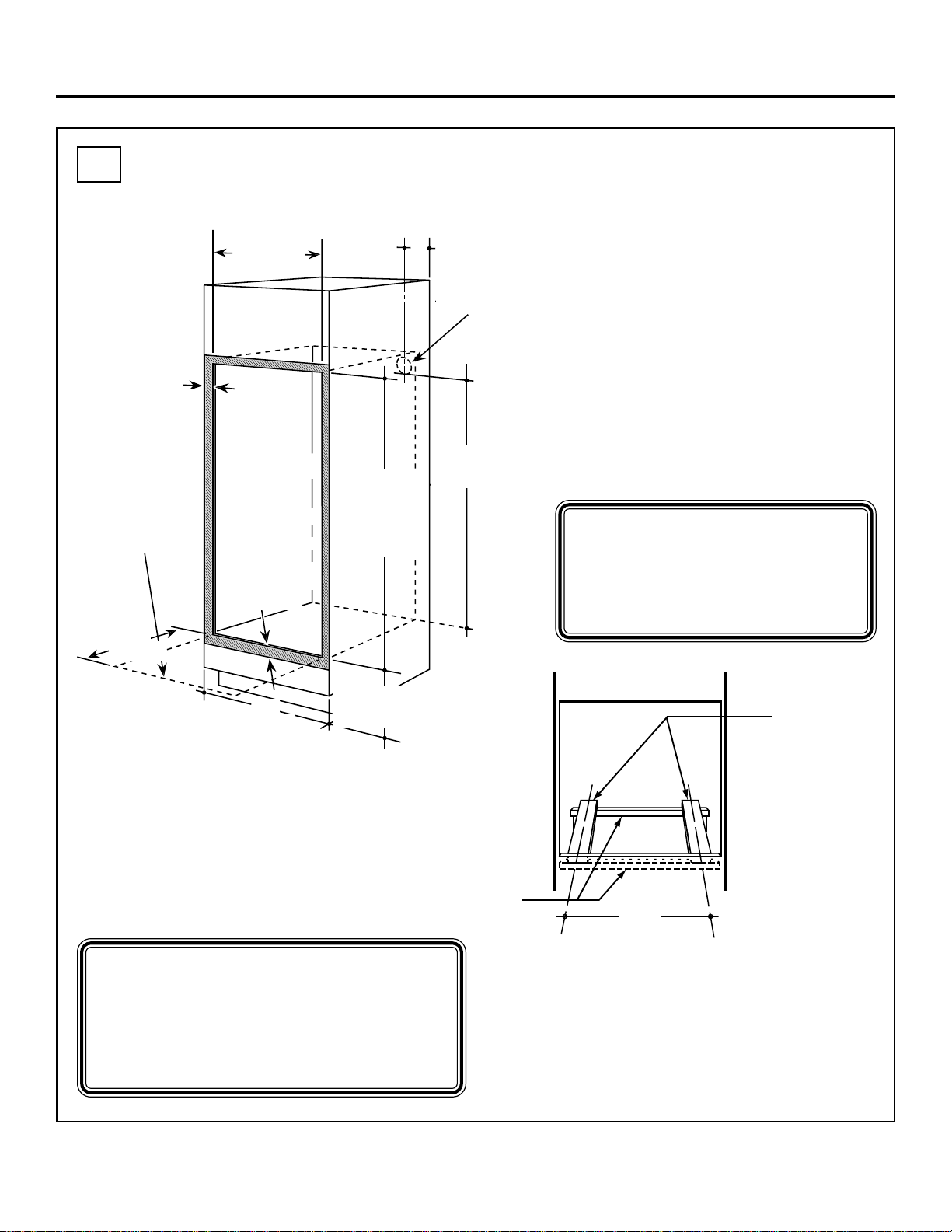
Cutout for Single Built-In Oven
Allow 11/16”
(1.75 cm) for
overlap of oven
over side edges
of cutout
21”
21"
(53.3 cm)
Cutout Width
CUTOUT
28 1/2” Min.
WIDTH
28 1/2" MIN.
28 5/8” Max.
28 5/8" MAX.
(72.4 to 72.7 cm)
Opening
Between
THE OPENING
Inside Walls
BETWEEN INSIDE
Must Be
WALLS MUST
At Least
BE AT LEAST
28 1/2"WIDE
28 1/2”
(72.4 cm)
Wide
Allow 1” (2.5 cm)
ALLOW 1" FOR
OVERLAP
minimum for
ON OVEN TOP
overlap of oven
AND BOTTOM
top and 11⁄
OF CUTOUT
(3.2 cm) overlap
of oven bottom
of cutout
CABINET
WIDTH
Cabinet
Width
30” (76.2 cm)
30"
”
4
7 3/4”
5"
(19.7 cm)
Max.
Cutout
CUTOUT
Height
HEIGHT
27 1/4” Min.
27 1/4" MIN.
27 5/16" MAX.
27 5/16” Max.
(69.2 to 69.4 cm)
RECOMMENDED
CUTOUT
Recommended
LOCATION
cutout location from
32 1/2"
floor 32 1/2” (82.6 cm)
FROM THE
FLOOR
22” (55.9 cm) Min.
BOTTOM OF
JUNCTION BOX
Junction Box
Location
(junction box
may be
located in
JUNCTION BOX
adjacent
LOCATION
cabinet)
22" TO
to Bottom of
Junction Box
Cabinet Width 30” (76.2 cm)
Recommended
Cutout Location
from Floor 32 1/2” (82.6 cm)
Cutout Depth 23 1/2” (59.7 cm) Min.
Cutout Width 28 1/2” (72.4 cm) Min.
28 5/8” (72.7 cm) Max.
Cutout Height 27 1/4” (69.2 cm) Min.
27 5/16” (69.4 cm) Max.
NOTE: If the cabinet does
not have a front frame and
the sides are less than 3/4”
(1.9 cm) thick, shim both
sides equally to establish
the cutout width.
If the cabinet does not have a solid bottom,
two braces or runners must be installed
level with the bottom of the cutout to
support the weight of the oven. For single
ovens, the runners and braces must
support 200 lbs. (90 kg).
NOTE: If marks, blemishes or the
cutout opening are visible above the
installed oven, it may be necessary to
add wood shims under the runners and
front trim until the marks or opening
are covered.
Side by Side Installations
Install two wall ovens in separate cutouts.
Allow 2″ (5.1 cm) min. between cutouts.
Cutout –
Observe all
dimensions
and
requirements.
2″ (5.1 cm)
Min.
Cutout –
Observe all
dimensions
and
requirements.
Install a
2" x 4" or
EQUIVALENT
solid bottom
RUNNERS
or 2” x 4”
(5 cm x 10 cm)
or equivalent
runners level
with bottom
of cutout
Suitable
Bracing
to Support
Runners
C
L
21 5/8"
21 5/8”
OVER CENTERLINE
(54.9 cm)
OF CABINET
Over Centerline
of Cabinet
The solid bottom or runners must be level
with the bottom of the cutout, or the bottom
trim may not install correctly and then
interfere with the door opening.
This oven is not approved for
stackable installation.
4
Page 5
Installation Instructions
A2
Allow a minimum
ALLOW A MINIMUM OF 21"
of 21” (53.3 cm) for
FOR CLEARANCE TO
clearance to adjacent
ADJACENT CORNERS,
corners, drawers,
DRAWERS, WALLS ETC.
walls, etc. when
WHEN THE DOOR
door is open
Cutout for Double Built-In Oven
ALLOW 11/16"
FOR OVERLAP
Allow 11/16”
OF THE OVEN
OVER SIDE EDGES
(1.8 cm) for
OF CUTOUT
overlap of oven
over side edges
of cutout
IS OPENED.
21”
21"
(53.3 cm)
Cutout
Width
28 1/2”
CUTOUT
(72.4 cm) Min.
WIDTH
28 1/2" MIN.
28 5/8”
28 5/8" MAX.
(72.7 cm) Max.
Opening
Between
Inside Walls
Must Be
At Least
THE OPENING
BETWEEN INSIDE
28 1/2”
WALLS MUST
(72.4 cm)
BE AT LEAST
Wide
28 1/2"WIDE
Allow 1” (2.5 cm)
minimum for
overlap of oven
ALLOW 1" FOR
top and 11⁄
OVERLAP
(3.2 cm) overlap
ON OVEN TOP
of oven bottom
AND BOTTOM
of cutout
OF CUTOUT
”
4
7 3/4”
(19.7 cm)
Max.
Cutout
Height
51 13/16”
CUTOUT
(131.6 cm) Min.
HEIGHT
51 15/16”
51 13/16" MIN.
(131.8 cm) Max.
51 15/16" MAX.
5"
Junction Box
JUNCTION BOX
Location
LOCATION
47” (119.4 cm) Min.
47" TO
to Bottom of
BOTTOM OF
JUNCTION BOX
Junction Box
Cabinet Width 30” (76.2 cm)
Recommended
Cutout
Location
from Floor 12” (30.5 cm)
Cutout Depth 23 1/2” (59.7 cm) Min.
Cutout Width 28 1/2” (72.4 cm) Min.
28 5/8” (72.7 cm) Max.
Cutout Height 51 13/16” (131.6 cm) Min.
51 15/16” (131.8 cm) Max.
NOTE: If the cabinet does
not have a front frame and the
sides are less than 3/4” (1.9 cm)
thick, shim both sides equally
to establish the cutout width.
Recommended cutout
RECOMMENDED
30”
30"
(76.2 cm)
CABINET
Cabinet
WIDTH
Width
CUTOUT LOCATION
location from floor
12" FROM THE FLOOR
12” (30.5 cm)
If the cabinet does not have a solid bottom,
two braces or runners must be installed
level with the bottom of the cutout to
support the weight of the oven. For double
ovens, the runners and braces must
support 375 lbs. (169 kg).
NOTE: If marks, blemishes or the
cutout opening are visible above the
installed oven, it may be necessary to
add wood shims under the runners and
front trim until the marks or opening
are covered.
Install a
2" x 4" or
EQUIVALENT
solid bottom
RUNNERS
or 2” x 4”
(5 cm x 10 cm)
or equivalent
runners level
with bottom
of cutout
Suitable
Bracing
to Support
UITABLE
Runners
RACING
O SUPPORT
UNNERS
C
L
21 5/8”
21 5/8"
OVER CENTERLINE
(54.9 cm)
OF CABINET
Over Centerline
of Cabinet
The solid bottom or runners must be level
with the bottom of the cutout, or the bottom
trim may not install correctly and then
interfere with the door opening.
5
Page 6
Installation Instructions
A3
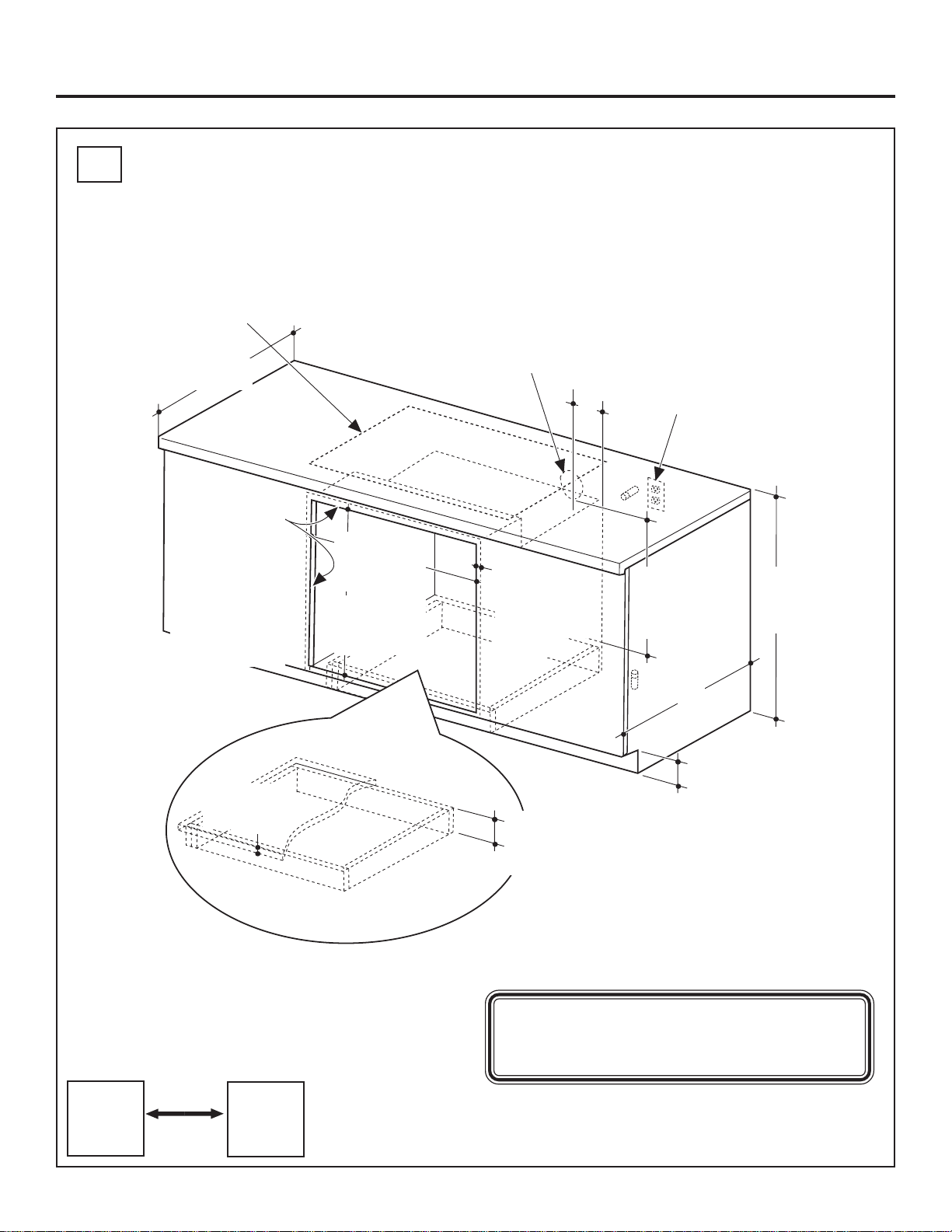
Cutout for Single Built-In Oven Under Counter
Gas or electric cooktops may
be installed over this oven.
See cooktop installation
instructions for cutout size.
See label on top of oven for
approved cooktop models.
25”
(63.5 cm)
Top and/or side fillers
may be necessary
if unit is positioned
between existing
cabinets. Be sure
they are attached
securely, since they
will anchor the oven
in the cabinet.
28 1/2”
(72.4 cm) Min.
28 5/8”
(72.6 cm) Max.
27 1/4”
(69.2 cm) Min.
27 5/16”
(69.4 cm) Max.
240V / 208V
Junction Box
Location (junction
box may be in
adjacent cabinet)
Allow 1” (2.5 cm)
overlap top of
oven and
11/16” (1.8 cm)
overlap side
edges of
cutout
7 3/4”
(19.7 cm)
Max.
Gas and electrical connections for
30” (76.2 cm) gas cooktop must be
located in an adjacent accessible
location to the right. For 36” (91.4 cm)
gas cooktop, the connections may be
made to the left.
22” (55.9 cm)
Min. Above
Support
Platform
36” (91.4 cm)
Typical
Countertop
Height
3/4” (1.9 cm)
Support Platform
Required
MUST SUPPORT 200 LBS.
(90 KG)
Side by Side Installations
Install two wall ovens in separate cutouts.
Allow 2″ (5.1 cm) min. between cutouts.
Cutout –
Observe all
dimensions
and
requirements.
2″ (5.1 cm)
Min.
Cutout –
Observe all
dimensions
and
requirements.
24”
(61 cm)
4” (10.2 cm)
Typical
Toekick
Must
match
toekick
height
NOTE: This oven is only approved to be
installed under the specific models as
labeled on this unit.
6
Page 7
Cabinetry
A4
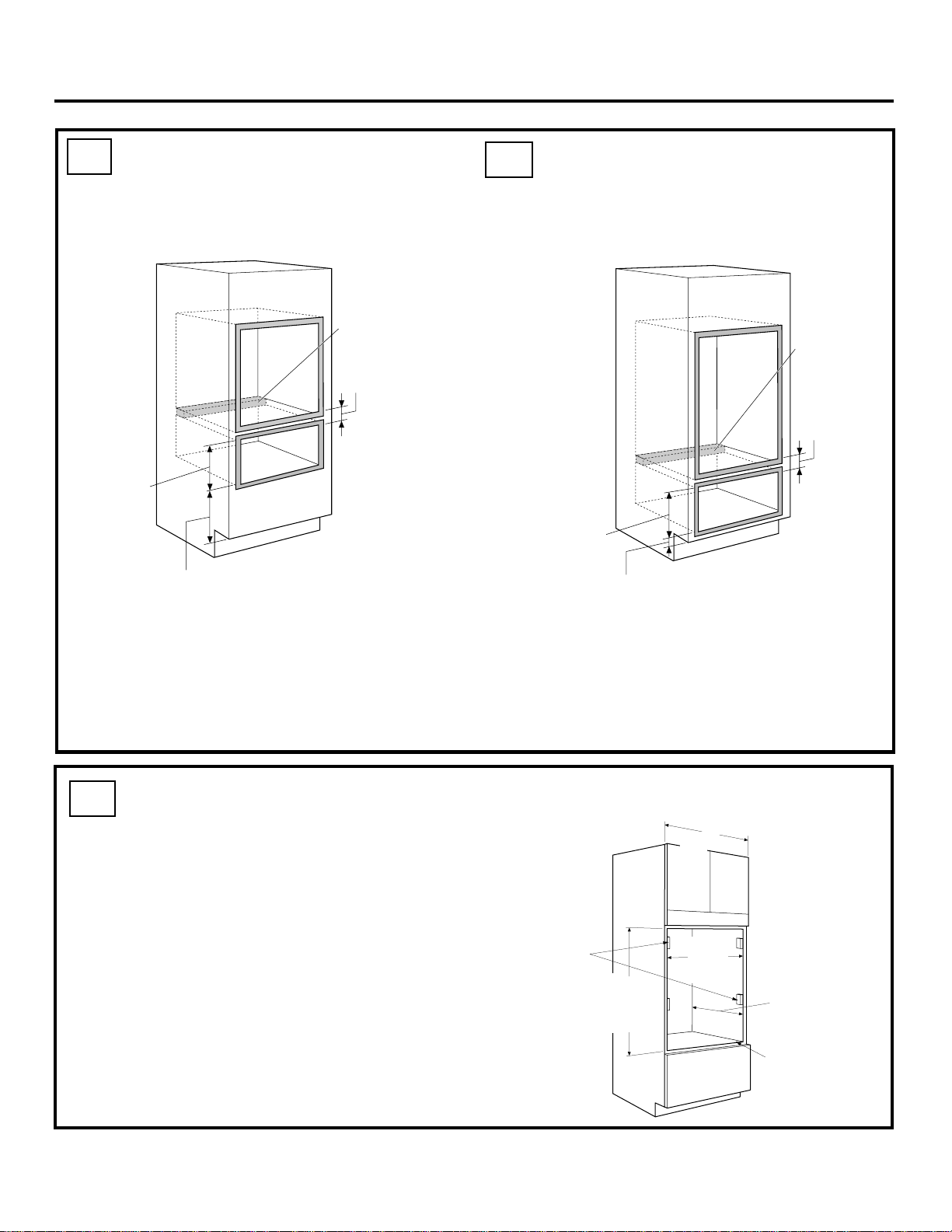
Single Oven Cutout for Installation Over a Monogram Warming Drawer
Anti-Tip Block Against
Rear Wall Per Warming
Drawer Requirement
2” (5.1 cm) Min.
Per Warming
Drawer
Requirement
1” (2.5 cm) Min. Above Toekick or
Adjust to Oven Installation Height
NOTE: Additional clearances between cutouts
may be required. Check to be sure the oven
supports above the Warming Drawer location
do not obstruct the required interior depth and
height.
NOTE: Install the
oven only with
specific models
listed on the label
located on top of
the oven.
A5
Double Oven Cutout for Installation Over a Monogram Warming Drawer
Anti-Tip Block
Against Rear
Wall Per
Warming
Drawer
Requirement
Per Warming
Drawer
Requirement
1” (2.5 cm) Min. Above Toekick
• When installing a Monogram Warming
Drawer below a single or double oven, a
separate 120V, 60 Hz, properly grounded
receptacle must be installed. Refer to
installation instructions packed with the
Warming Drawer for specific installation
requirements.
2” (5.1 cm)
Min.
A6
Cutout for Frameless Cabinets
Frameless Cabinets
Whenever possible, order 30” (76.2 cm)
frameless cabinet with the cutout sided to fit
the oven. If using stock cabinets, additional
finished filler pieces may be required to
cover the opening.
• A stock frameless cabinet cutout width
may be up to 28 3/4” (73 cm). If necessary,
add 1/2” (1.3 cm) cleats to the sides, flush
with the front edge of the side panels to
accept mounting screws.
30”
(76.2 cm)
Install 1/2”
(1.3 cm)
Cleats to
Hold Oven
Mounting
Screws
Double
51 15/16” (131.8 cm)
Single
27 5/16” (69.2 cm)
28 1/2” (72.4 cm)
Min.
28 5/8” (72.7 cm)
Max.
Cabinet Depth
23 1/2” (59.7 cm)
Min. From Inside
Back to Front of
Cabinet Frame
or Side Panel
3/4” (1.9 cm) Min.
Thick Bottom Shelf
Cut Back Flush
with Front of
Side Panel
7
Page 8
Cabinetry
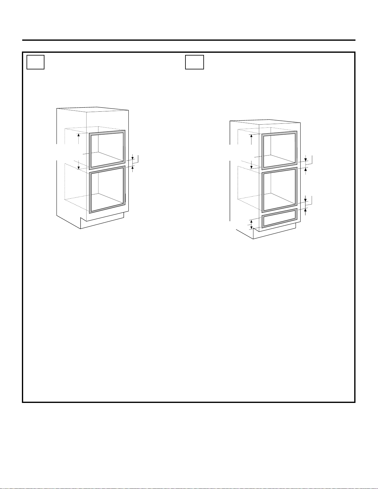
A7
Single Oven Cutout for Installation Below a Monogram Advantium or Microwave Oven
Per Advantium or
Microwave Oven
Requirement
NOTE: The middle rail separating the two
openings may need to be larger than the 2”
(5.1 cm) minimum shown. Always refer to the
individual installation instructions packed with
each product for specific requirements.
Combined Advantium or
Microwave Oven and W all Oven
Installation:
When installed in combination with a
Monogram single wall oven, use separate
electrical junction boxes.
• Refer to the Advantium or microwave
oven installation instructions for electrical
requirements of that product.
• These connections must be made
by a qualified electrician. All electrical
connections must meet National Electrical
Code or prevailing local codes.
2” (5.1 cm) Min.
Note: Install the
oven only with
specific models
listed on the label
located on top of
the oven.
A8
Single Oven Cutout for Installation Between a Monogram Advantium or Microwave Oven and a Monogram Warming Drawer
Per Advantium or
Microwave Oven
Requirement
Per Warming Drawer
Requirement
NOTE: Additional clearances may be
required. Check to be sure the oven
supports above the Warming Drawer
do not obstruct the required interior depth
and height. The middle rail separating the
openings may need to be larger than the
2” (5.1 cm) minimum shown. Always refer to
the individual installation instructions packed
with each product for specific requirements.
Warming Drawer Combined
with Advantium or Microwave
Oven and Single Oven:
Install a separate 120V, 60Hz, properly
grounded receptacle. See installation
instructions packed with each product
for specific requirements.
2” (5.1 cm) Min.
2” (5.1 cm) Min.
8
Page 9
Installation Instructions
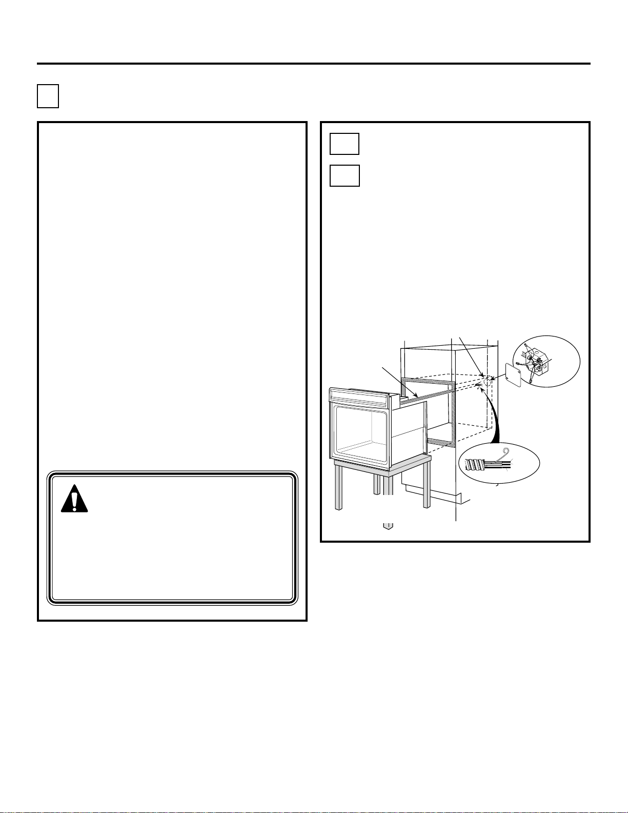
B
Electrical Connections
ATTENTION INSTALLER
All electric wall ovens must be hard wired
(direct wired) into an approved junction
box. A plug and receptacle is NOT permitted
on these products.
DO NOT shorten the flexible conduit.
The conduit strain relief clamp must be
securely attached to the junction box
and the flexible conduit must be securely
attached to the clamp. If the flexible
conduit will not fit within the clamp, do not
install the oven until a clamp of the proper
size is obtained.
NOTE TO ELECTRICIAN: The 3 power
leads supplied with this appliance are
UL recognized for connection to heavier
gauge household wiring. The insulation
of these 3 leads is rated at temperatures
much higher than the temperature rating
of household wiring. The current carrying
capacity of the conductor is governed
by the wire gauge and the temperature
rating of the insulation around the wire.
B1
B2
Turn off the circuit breaker or remove
fuses to the oven branch circuit.
With the oven supported on a table
or platform in front of the cabinet
opening, connect the flexible conduit
to the electrical junction box as shown
below. Position the conduit in such a
manner that it will lie on top of the
oven in a natural loop when the oven
is installed. You will need to purchase
an appropriate strain relief clamp to
complete the connection of the conduit
to the junction box.
Junction Box
Location
Conduit
BARE
GROUND
RED
WHITE
BLACK
GROUND
WIRE
WARNING: Improper
connection of aluminum house
wiring to copper leads can
result in an electrical hazard or fire.
Use only connectors designed for
joining copper to aluminum and follow
the manufacturer’s recommended
procedure closely.
Place oven on a
support to assist in
connecting conduit
Strain Relief Clamp
(not included)
must be used at
Junction Box
9
Page 10
Installation Instructions
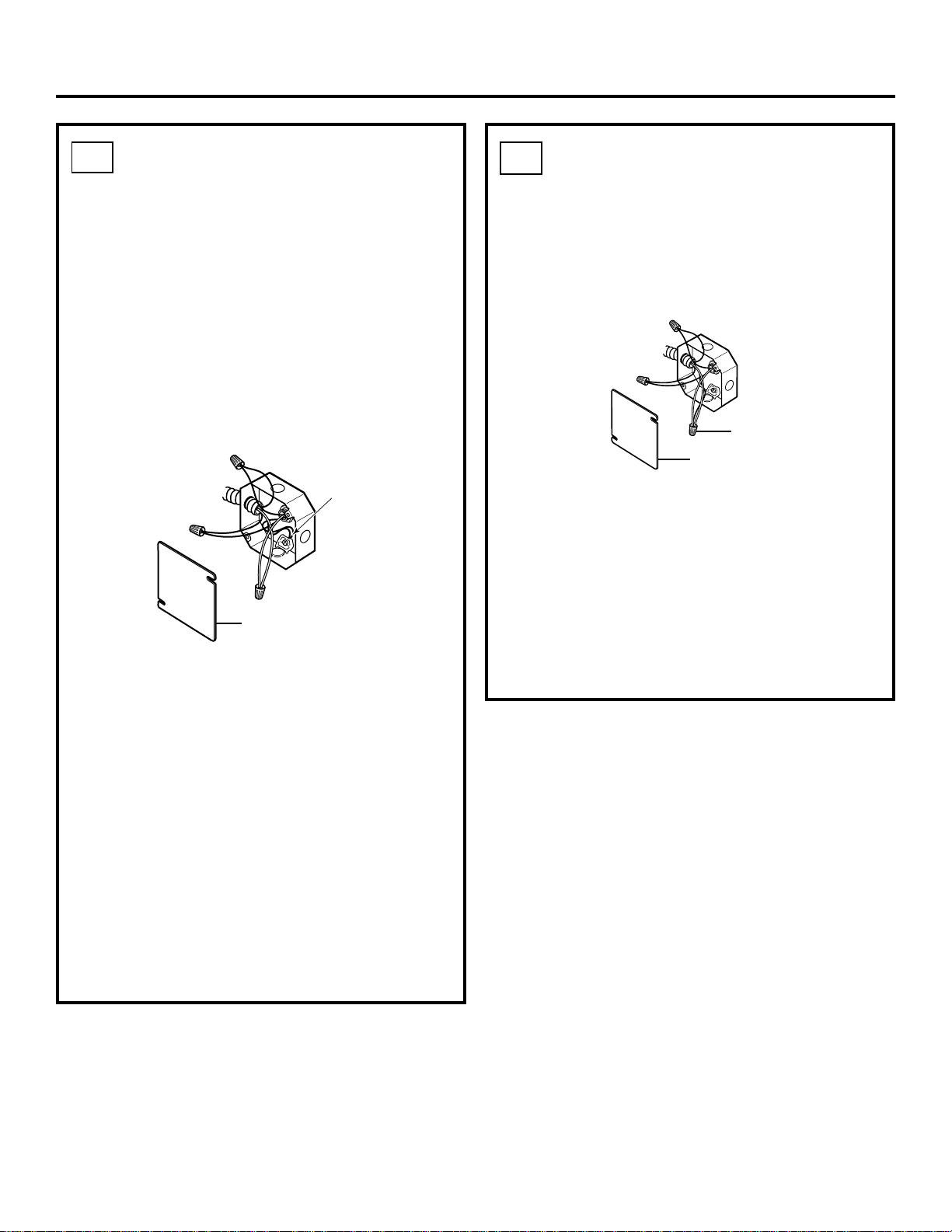
B3
New Construction and
Four-Conductor Branch
Circuit Connection
• When installing in new construction, or
• When installing in a mobile home, or
• When installing in a recreational vehicle, or
• When local codes do not permit grounding through
neutral:
a. Cut the neutral (white) lead from the crimp.
Re-strip the neutral (white) lead to expose the
proper length of conductor.
Ground
Wire
Junction Box
Cover
B4
Three-Conductor Branch
Circuit Connection
When connecting to a three-conductor branch circuit,
if local codes permit:
a. Connect the bare oven ground conductor with the
crimped neutral (white) lead to the branch circuit
neutral (white or gray in color), using a wire nut.
Ground and
Neutral Wires
Junction Box
Cover
b. Connect the oven red lead to the branch circuit
red lead in accordance with local codes, using a
wire nut.
c. Connect the oven black lead to the branch circuit
black lead in accordance with local codes, using a
wire nut. If the residence red, black or white leads
are aluminum conductors, see WARNING on
page 9.
b. Attach the appliance grounding lead (green or
bare copper) in accordance with local codes. If the
residence grounding conductor is aluminum, see
WARNING on page 9.
c. Connect the oven neutral (white) lead to
the branch circuit neutral (white or gray) in
accordance with local codes, using a wire nut.
d. Connect the oven red lead to the branch circuit
red lead and the oven black lead to the branch
circuit black lead in accordance with local codes,
using wire nuts. If the residence red, black or
white leads are aluminum conductors, see
WARNING on page 9.
e. Install Junction Box Cover.
d. Install Junction Box Cover.
10
Page 11
Installation Instructions
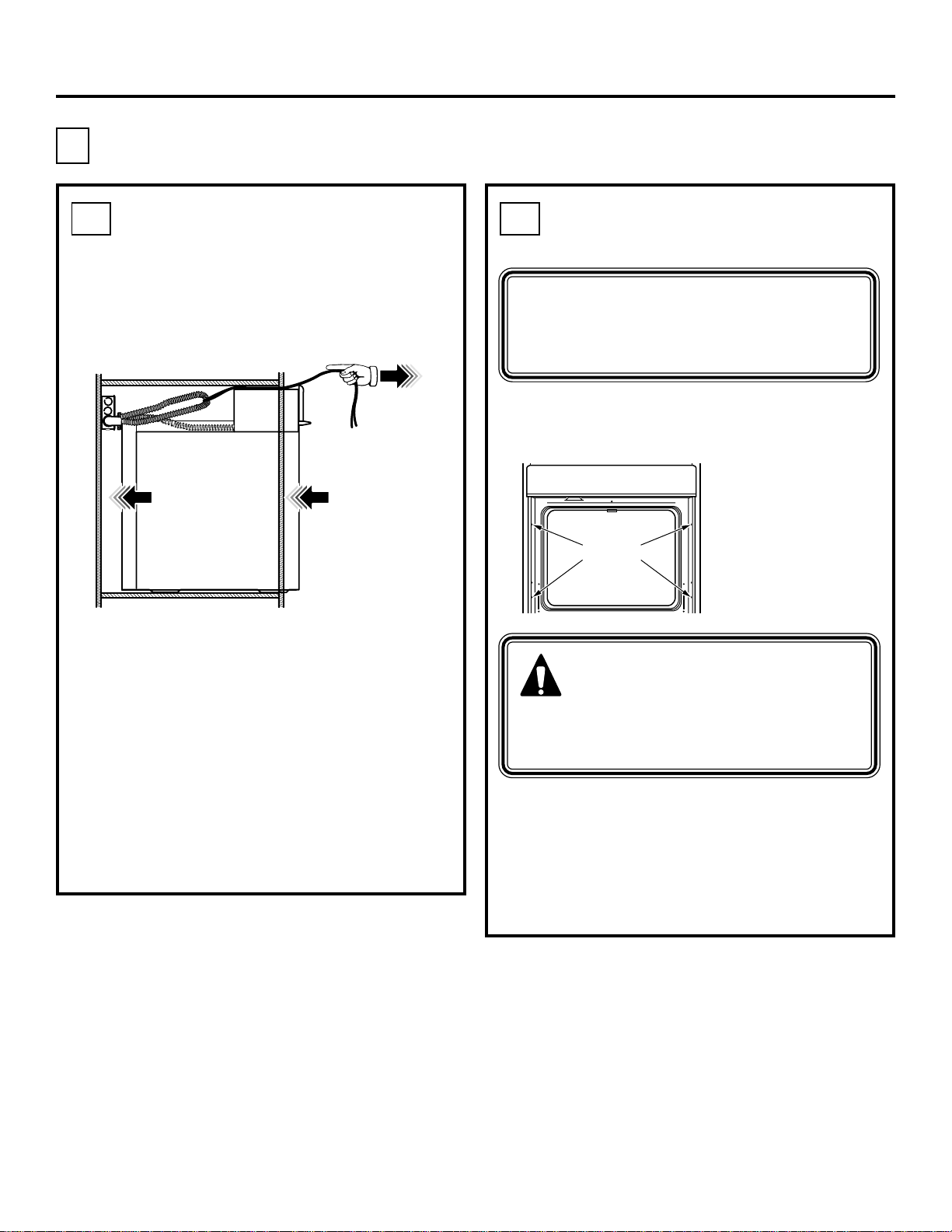
C
Securing the Oven in the Opening
C1 C2
Sliding the Oven Into
the Opening
a. Loop (do not tie) a 36” (91 cm) string
around the conduit before the oven is slid
into place. This will keep the conduit from
falling behind the oven.
a. Drill through the mounting holes (top and
Pull out on
string loop
while pushing
the oven into
the cabinet
b. Lift oven into cabinet cutout using the oven
opening as a grip. Carefully push against
oven front frame. Do not push against
outside edges.
c. As you slide the oven back, pull the string
so that the conduit will lie on top of the
oven in a natural loop.
d. When you are sure the conduit is out of the
way, slide the oven 3/4 way back into the
opening. Remove the string by pulling on
one end of the loop.
b. Secure the oven to cabinet with screws
NOTE: If the cabinet is particle board, you
must use #8 x 3/4” (1.9 cm) particle board
screws. These may be purchased at any
hardware store.
Drilling the Pilot Holes
and Mounting the Oven
NOTE: Before drilling the pilot holes,
make sure the oven is pushed as far
back into the opening as it will go
and centered.
bottom) of the side trim, for the #8 screws
provided.
Mounting
Hole
Locations
(Hole
Locations
may vary)
WARNING:
screws must be used. Failure to
do so could result in the oven
falling out of the cabinet causing
serious injury.
provided.
The screws must
be a minimum of
1/4” (0.64 cm)
from the front
of the cutout.
Mounting
11
Page 12
Installation Instructions
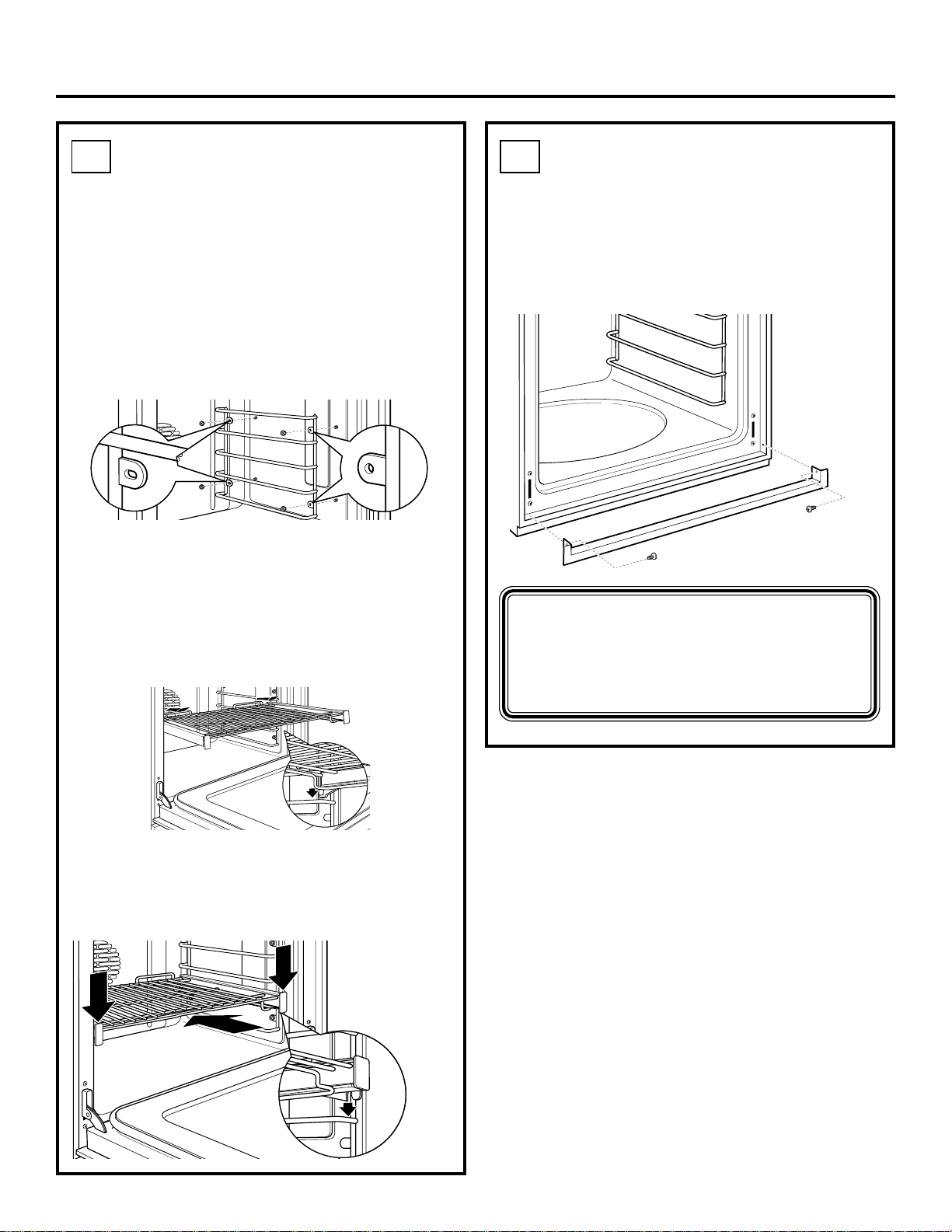
C3
Installing the Oven
Rack Supports and
Oven Racks
Oven Rack Supports
Place the rack support with the slotted
holes over the rear bolts and the round holes
over the front bolts. Using an adjustable
wrench, lightly secure with four nuts but
do not overtighten or the enamel could be
chipped. Repeat for the second rack support.
Slotted
holes over
rear bolts
Oven Racks
a. Place the rear rack locks over and onto
the rack supports (five rack positions are
available, including the top position).
Round
holes over
front bolts
C4
Installing the Metal
Bottom Trim
a. Place the bottom trim between the side
trim and against the bottom of the cutout.
b. Using two trim screws provided, secure the
bottom trim through the holes in the trim.
IMPORTANT: If this unit is ever
removed from the cabinet or the oven
is ever pulled out for service, the trim
must be removed first or damage to
the trim will occur.
b. Slide the rack all the way in until the rear
rack locks are secure on the rear rack
supports, and press the front rack locks
onto the front rack supports.
Slide the rack
all the way in
and push
down to lock
the front rack
locks onto the
front rack
supports
12
Page 13
Installation Instructions
D
Replacing the Oven Door
NOTE:
may need help lifting the door high
enough to slide it into the hinge slots.
Do not lift the door by the handle.
D1
The oven door is heavy. You
Lift the oven door by
placing one hand on
each side. The door is
heavy, so you may need
help. Do not lift the door
by the handle.
D3
D4
D5
Open the oven door as far as it
will open.
Push the hinge locks up against the
front frame of the oven cavity, to the
locked position.
Hinge in
Locked Position
Notch of Hinge
Securely Fitted
into Bottom of
Hinge Slot
Close the oven door.
With the door at the same angle as
D2
the removal position, which is most of
the way closed, seat the notch of the
hinge arm into the bottom edge of the
hinge slot. The notch of the hinge arm
must be fully seated into the
bottom of the slot.
Hinge Arm
Bottom Edge
of Slot
Hinge Notch
13
Page 14
Installation Instructions
Pre-Test Checklist
Remove all protective film, if present, and
any stickers.
Check to be sure that all wiring is secure
and not pinched or in contact with moving
parts.
NOTE TO ELECTRICIAN: You must
unplug the green wire (near where the
long flexible conduit exits the unit)
when conducting high-potential testing.
Please replug prior to operation.
Operation Checklist
Remove all items from the inside
of the oven.
Check that conduit is securely connected
to the junction box.
Turn on the power to the oven. (Refer to
your Owner’s Manual.) Verify that the bake
and broil units, and all cooking functions
operate properly.
Check that the circuit breaker is not tripped
nor the house fuse blown.
Check that the bottom trim is installed
properly (see page 12).
Check to be sure the mounting screws are
installed and flush with the side trim (see
page 11).
NOTE TO ELECTRICIAN: The power
leads supplied with this appliance are
UL recognized for connections to larger
gauge household wiring. The insulation
of these leads is rated at temperatures
much higher than the temperature
rating of household wiring. The current
carrying capacity of a conductor
is governed by the wire gauge and also
the temperature rating of the insulation
around the wire.
NOTE: ALUMINUM WIRING
See your Owner’s Manual for
troubleshooting list.
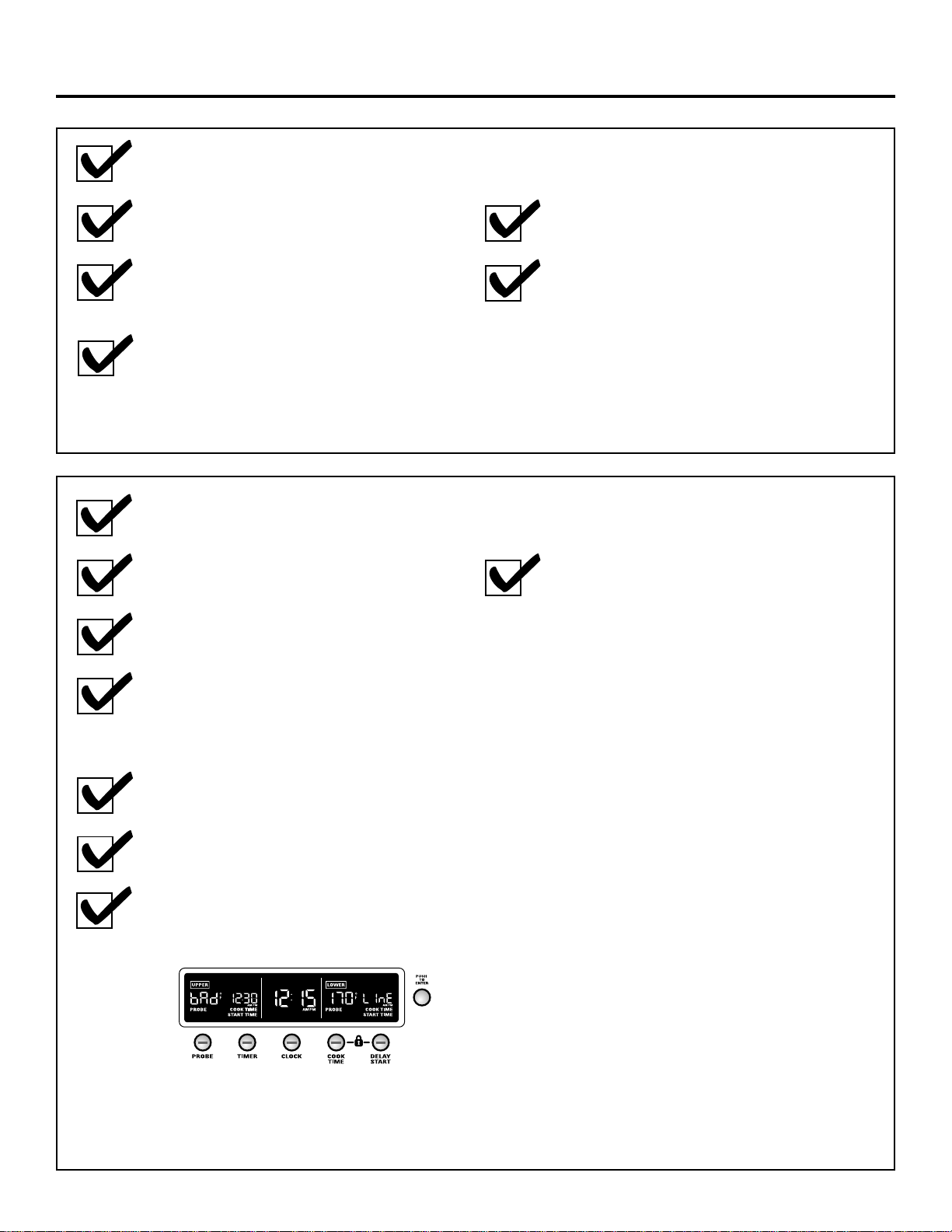
If "bAd" "LInE" appears in the display
when the power is turned on, the house
wiring connections are incorrect.
A. WARNING: IMPROPER
CONNECTION OF ALUMINUM
HOUSE WIRING TO THE COPPER
LEADS CAN RESULT IN AN
ELECTRICAL HAZARD OR FIRE.
B. Splice copper wires to aluminum
wiring using special connectors
designed and UL approved for
joining copper to aluminum,
and follow the manufacturer’s
recommended connector procedure
closely.
NOTE: Wire used, location and
enclosure of splices, etc., must
conform to good wiring practice and
local codes.
14
Page 15

Directives
Four mural encastré
modèles de 30 po (76,2 cm)
d’installation
ZET1, ZET2
Si vous avez des questions, composez le 1.800.561.3344 ou visitez
notre site web à : www.electromenagersge.ca
Avant de commencer
Lisez complètement et attentivement les directives
suivantes.
• IMPORTANT—Conservez ces
directives pour votre inspecteur local.
• IMPORTANT—Respectez tous
les codes et les décrets en vigueur.
• Note à l’intention de l’installateur—
Assurez-vous de laisser ces directives
chez le consommateur.
• Note au consommateur—Conservez ces
directives pour consultation ultérieure.
• II est de la responsabilité de l’installateur
de procéder à une installation appropriée.
Un dysfonctionnement du produit qui
résulterait d’une installation incorrecte
ne serait PAS couvert par la garantie.
• NOTE—Cet appareil doit être mis à la terre
adéquatement.
• AVIS IMPORTANT À
L’INSTALLATEUR :
Tous les fours muraux encastrés doivent
être raccordés (raccordement direct) dans
un boîtier de jonction homologué. Une fiche
et une prise de courant ne sont PAS
autorisées pour brancher ces produits.
Pièces incluses
(L’aspect des pièces peut varier.)
Vis à bois de 5/8 po
Vis à bois
de 3/4 po (Vis à
bois à tête plate
Phillips 8-18 x .750)
(Vis à bois à tête
bombée Phillips
8A8 x .625)
Assemblage de
garniture inférieure
métallique
Matériel requis
Bague anti-traction
pour conduit de
1/2 po
Boîte de
jonction
Outils requis
Perceuse électrique
ou manuelle et mèche
de 3 mm (1/8 po)
Tournevis à pointe
cruciforme
Serre-fils
Ficelle de
91 cm (36 po)
31-10649-2 07-07 JR
Clef réglable
15
Page 16

Directives d’installation
CONSIGNES DE SÉCURITÉ IMPORTANTES
Pour votre sécurité
• Assurez-vous que votre four est bien monté
par un installateur qualifié ou un technicien
de service.
• Assurez-vous que les armoires de cuisine
et les revêtements de mur autour du four peuvent
supporter la température (pouvant atteindre 93 °C
[200 °F] produite par le four.
• Assurez-vous que votre four est monté en
toute sécurité dans une enceinte qui est bien
fixée à la structure de votre maison. Toute
pression appliquée sur la porte du four peut faire
tomber le four et occasionner des blessures. Ne
permettez à personne de grimper, de s’asseoir,
de se tenir sur la porte du four ou de s’y
suspendre.
AVERTISSEMENT :
Vous devez couper l’alimentation
électrique du four avant de le
brancher. Le défaut de se conformer
à cette procédure peut entraîner des
blessures sévères et même la mort.
Alimentation
Cet appareil doit être alimenté avec un courant
de tension et de fréquence appropriées et
connecté à un circuit individuel adéquatement
mis à la terre et protégé par un disjoncteur ou un
fusible. Veuillez consulter la plaque signalétique
située sur le cadre du four afin de déterminer la
puissance nominale du produit. Servez-vous du
tableau ci-dessous pour déterminer la protection
minimale recommandée du circuit dédié.
Alimentation (suite)
La plaque signalétique est située sur la garniture
latérale du four, sur le devant du cadre latéral ou sur
le devant du cadre inférieur.
Emplacement
de la plaque
signalétique
Nous vous recommandons de faire réaliser
le câblage électrique et le branchement de
votre four par un électricien qualifié. Après le
montage, demandez à l’électricien de vous montrer
l’emplacement de l’interrupteur d’isolement de
votre four .
Vérifiez, auprès de votre compagnie d’électricité,
le code de l’électricité régissant les installations
électriques dans votre région. Si vous ne branchez
pas votre four conformément au code en vigueur,
vous vous exposez à une situation dangereuse. En
l’absence d’un code de l’électricité local, votre four
doit être muni d’un branchement et de fusibles qui
répondent à la norme CAN/CSA C22.2 No. O-M91,
ou la dernière édition.
Vous devez utiliser un circuit électrique présentant
les caractéristiques suivantes : courant monophasé
(c.a.), trifilaire, 208Y/120 volts ou 240/120 volts,
60 hertz. Si vous vous branchez à du câblage en
aluminium, vous devez utiliser des connecteurs
correctement montés et approuvés pour ce type
de câblage.
Puissance Puissance Calibre
nominale en kW nominale recommandé pour
240V en kW 208 V le circuit (dédié)
≤ 4,8 kW ≤ 4,1 kW 20 ampères
4,9 kW à 7,2 kW 4,3 kW à 6,2 kW 30 ampères
7,3kW à 9,6kW 6,3kW à 8,3kW 40 ampères
9,7kW à 12,0kW 8,4kW à 10,4kW 50 ampères
16
Page 17

Directives d’installation
Hinge
Unlocked
Position
Hinge
Arm
Liste de vérification avant montage
TOUTES LES DIRECTIVES D’INSTALLATION
QUI SUIVENT SONT PRÉVUES POUR
L ’INSTALLATION DE FOURS ENCASTRÉS
SIMPLES OU DOUBLES!
Pour enlever la porte (si nécessaire)
II est possible d’enlever la porte du four pour
faciliter l’installation, bien que cela ne soit pas
obligatoire. Pour enlever la porte :
Ouvrez la porte jusqu’à son angle maximum.
Sonde
thermique
Enlevez tous les matériaux d’emballage.
Vérifiez derrière les charnières et sous
le faux fond. Enlevez les étiquettes sur la face
extérieure de la porte, la matière plastique sur
les garnitures et le panneau ainsi que le ruban
collé autour du four. Enlevez aussi les vis
d’expédition qui fixent le four sur sa base.
Supports de
grille avec écrous
hexagonaux
Grilles du four
Lèchefrite
et claie
EASY INSTALLATION OF YOUR NEW
IMPORTANT- Save these instructions for local inspector’s use.
IMPORTANT- Save these instructions for local inspector’s use.
IMPORTANT- Save these instructions for local inspector’s use.
IMPORTANT- Save these instructions for local inspector’s use.
IMPORTANT- Save these instructions for local inspector’s use.
IMPORTANT- Save these instructions for local inspector’s use.
IMPORTANT- Save these instructions for local inspector’s use.
IMPORTANT- Save these instructions for local inspector’s use.
IMPORTANT- Save these instructions for local inspector’s use.
IMPORTANT- Save these instructions for local inspector’s use.
IMPORTANT- Save these instructions for local inspector’s use.
IMPORTANT- OBSERVE ALL GOVERNING CODES AND ORDIANCES.
IMPORTANT- OBSERVE ALL GOVERNING CODES AND ORDIANCES.
IMPORTANT- OBSERVE ALL GOVERNING CODES AND ORDIANCES.
IMPORTANT- OBSERVE ALL GOVERNING CODES AND ORDIANCES.
IMPORTANT- OBSERVE ALL GOVERNING CODES AND ORDIANCES.
IMPORTANT- OBSERVE ALL GOVERNING CODES AND ORDIANCES.
IMPORTANT- OBSERVE ALL GOVERNING CODES AND ORDIANCES.
IMPORTANT- OBSERVE ALL GOVERNING CODES AND ORDIANCES.
IMPORTANT- OBSERVE ALL GOVERNING CODES AND ORDIANCES.
IMPORTANT- OBSERVE ALL GOVERNING CODES AND ORDIANCES.
IMPORTANT- OBSERVE ALL GOVERNING CODES AND ORDIANCES.
Note to Installer- Be sure to leave these instructions with the consumer.
Note to Installer- Be sure to leave these instructions with the consumer.
Note to Installer- Be sure to leave these instructions with the consumer.
Note to Installer- Be sure to leave these instructions with the consumer.
Note to Installer- Be sure to leave these instructions with the consumer.
Note to Installer- Be sure to leave these instructions with the consumer.
Note to Installer- Be sure to leave these instructions with the consumer.
Note to Installer- Be sure to leave these instructions with the consumer.
Note to Installer- Be sure to leave these instructions with the consumer.
Note to Installer- Be sure to leave these instructions with the consumer.
Note to Installer- Be sure to leave these instructions with the consumer.
Note to Installer- Be sure to leave these instructions with the consumer.
OWNER- Keep these instructions for future reference.
OWNER- Keep these instructions for future reference.
OWNER- Keep these instructions for future reference.
OWNER- Keep these instructions for future reference.
OWNER- Keep these instructions for future reference.
OWNER- Keep these instructions for future reference.
OWNER- Keep these instructions for future reference.
OWNER- Keep these instructions for future reference.
OWNER- Keep these instructions for future reference.
OWNER- Keep these instructions for future reference.
OWNER- Keep these instructions for future reference.
OWNER- Keep these instructions for future reference.
Before you begin-Read these instructions completely and carefully.
Before you begin-Read these instructions completely and carefully.
Before you begin-Read these instructions completely and carefully.
Before you begin-Read these instructions completely and carefully.
Before you begin-Read these instructions completely and carefully.
Before you begin-Read these instructions completely and carefully.
Before you begin-Read these instructions completely and carefully.
Before you begin-Read these instructions completely and carefully.
Before you begin-Read these instructions completely and carefully.
Before you begin-Read these instructions completely and carefully.
Before you begin-Read these instructions completely and carefully.
Before you begin-Read these instructions completely and carefully.
Note- This appliance must be properly grounded (if applicable).
Note- This appliance must be properly grounded (if applicable).
Note- This appliance must be properly grounded (if applicable).
Note- This appliance must be properly grounded (if applicable).
Note- This appliance must be properly grounded (if applicable).
Note- This appliance must be properly grounded (if applicable).
Note- This appliance must be properly grounded (if applicable).
Note- This appliance must be properly grounded (if applicable).
Note- This appliance must be properly grounded (if applicable).
Note- This appliance must be properly grounded (if applicable).
Note- This appliance must be properly grounded (if applicable).
Note- This appliance must be properly grounded (if applicable).
IMPORTANT- Save these instructions for local inspector’s use.
IMPORTANT- Save these instructions for local inspector’s use.
IMPORTANT- Save these instructions for local inspector’s use.
IMPORTANT- Save these instructions for local inspector’s use.
IMPORTANT- Save these instructions for local inspector’s use.
IMPORTANT- Save these instructions for local inspector’s use.
IMPORTANT- Save these instructions for local inspector’s use.
IMPORTANT- Save these instructions for local inspector’s use.
IMPORTANT- Save these instructions for local inspector’s use.
IMPORTANT- Save these instructions for local inspector’s use.
IMPORTANT- Save these instructions for local inspector’s use.
IMPORTANT- Save these instructions for local inspector’s use.
IMPORTANT- OBSERVE ALL GOVERNING CODES AND ORDIANCES.
IMPORTANT- OBSERVE ALL GOVERNING CODES AND ORDIANCES.
IMPORTANT- OBSERVE ALL GOVERNING CODES AND ORDIANCES.
IMPORTANT- OBSERVE ALL GOVERNING CODES AND ORDIANCES.
IMPORTANT- OBSERVE ALL GOVERNING CODES AND ORDIANCES.
IMPORTANT- OBSERVE ALL GOVERNING CODES AND ORDIANCES.
IMPORTANT- OBSERVE ALL GOVERNING CODES AND ORDIANCES.
IMPORTANT- OBSERVE ALL GOVERNING CODES AND ORDIANCES.
IMPORTANT- OBSERVE ALL GOVERNING CODES AND ORDIANCES.
IMPORTANT- OBSERVE ALL GOVERNING CODES AND ORDIANCES.
IMPORTANT- OBSERVE ALL GOVERNING CODES AND ORDIANCES.
IMPORTANT- OBSERVE ALL GOVERNING CODES AND ORDIANCES.
Note to Installer- Be sure to leave these instructions with the consumer.
Note to Installer- Be sure to leave these instructions with the consumer.
Note to Installer- Be sure to leave these instructions with the consumer.
Note to Installer- Be sure to leave these instructions with the consumer.
Note to Installer- Be sure to leave these instructions with the consumer.
Note to Installer- Be sure to leave these instructions with the consumer.
Note to Installer- Be sure to leave these instructions with the consumer.
Note to Installer- Be sure to leave these instructions with the consumer.
Note to Installer- Be sure to leave these instructions with the consumer.
Note to Installer- Be sure to leave these instructions with the consumer.
Note to Installer- Be sure to leave these instructions with the consumer.
Note to Installer- Be sure to leave these instructions with the consumer.
OWNER- Keep these instructions for future reference.
OWNER- Keep these instructions for future reference.
OWNER- Keep these instructions for future reference.
OWNER- Keep these instructions for future reference.
OWNER- Keep these instructions for future reference.
OWNER- Keep these instructions for future reference.
OWNER- Keep these instructions for future reference.
OWNER- Keep these instructions for future reference.
OWNER- Keep these instructions for future reference.
OWNER- Keep these instructions for future reference.
OWNER- Keep these instructions for future reference.
OWNER- Keep these instructions for future reference.
FOR YOUR SAFETY
FOR YOUR SAFETY
FOR YOUR SAFETY
FOR YOUR SAFETY
Note- This appliance must be properly grounded (if applicable).
Note- This appliance must be properly grounded (if applicable).
Note- This appliance must be properly grounded (if applicable).
Note- This appliance must be properly grounded (if applicable).
Note- This appliance must be properly grounded (if applicable).
Note- This appliance must be properly grounded (if applicable).
Note- This appliance must be properly grounded (if applicable).
Note- This appliance must be properly grounded (if applicable).
Note- This appliance must be properly grounded (if applicable).
Note- This appliance must be properly grounded (if applicable).
Note- This appliance must be properly grounded (if applicable).
Note- This appliance must be properly grounded (if applicable).
Before you begin-Read these
Before you begin-Read these
Before you begin-Read these
Before you begin-Read these
instructions completely and
instructions completely and
instructions completely and
instructions completely and
carefully.
carefully.
carefully.
carefully.
FOR YOUR SAFETY
FOR YOUR SAFETY
FOR YOUR SAFETY
FOR YOUR SAFETY
IMPORTANT- Save these
IMPORTANT- Save these
IMPORTANT- Save these
IMPORTANT- Save these
instructions for local inspector’s use.
instructions for local inspector’s use.
instructions for local inspector’s use.
instructions for local inspector’s use.
Before you begin-Read these
Before you begin-Read these
Before you begin-Read these
Before you begin-Read these
IMPORTANT- OBSERVE ALL
IMPORTANT- OBSERVE ALL
IMPORTANT- OBSERVE ALL
IMPORTANT- OBSERVE ALL
instructions completely and
instructions completely and
instructions completely and
instructions completely and
GOVERNING CODES AND ORDIANCES.
GOVERNING CODES AND ORDIANCES.
GOVERNING CODES AND ORDIANCES.
GOVERNING CODES AND ORDIANCES.
carefully.
carefully.
carefully.
carefully.
Note to Installer- Be sure to leave
Note to Installer- Be sure to leave
Note to Installer- Be sure to leave
Note to Installer- Be sure to leave
IMPORTANT- Save these
IMPORTANT- Save these
IMPORTANT- Save these
IMPORTANT- Save these
these instructions with the consumer.
these instructions with the consumer.
these instructions with the consumer.
these instructions with the consumer.
instructions for local inspector’s use.
instructions for local inspector’s use.
instructions for local inspector’s use.
instructions for local inspector’s use.
OWNER- Keep these instructions
OWNER- Keep these instructions
OWNER- Keep these instructions
OWNER- Keep these instructions
IMPORTANT- OBSERVE ALL
IMPORTANT- OBSERVE ALL
IMPORTANT- OBSERVE ALL
IMPORTANT- OBSERVE ALL
for future reference.
for future reference.
for future reference.
for future reference.
Note- This appliance must be
Note- This appliance must be
Note- This appliance must be
Note- This appliance must be
GOVERNING CODES AND ORDIANCES.
GOVERNING CODES AND ORDIANCES.
GOVERNING CODES AND ORDIANCES.
GOVERNING CODES AND ORDIANCES.
properly grounded (if applicable).
properly grounded (if applicable).
properly grounded (if applicable).
properly grounded (if applicable).
Note to Installer- Be sure to leave
Note to Installer- Be sure to leave
Note to Installer- Be sure to leave
Note to Installer- Be sure to leave
these instructions with the consumer.
these instructions with the consumer.
these instructions with the consumer.
these instructions with the consumer.
Before you begin-Read these
Before you begin-Read these
Before you begin-Read these
Before you begin-Read these
instructions completely and
instructions completely and
instructions completely and
instructions completely and
OWNER- Keep these instructions
OWNER- Keep these instructions
OWNER- Keep these instructions
OWNER- Keep these instructions
carefully.
carefully.
carefully.
carefully.
for future reference.
for future reference.
for future reference.
for future reference.
IMPORTANT- Save these
IMPORTANT- Save these
IMPORTANT- Save these
IMPORTANT- Save these
Note- This appliance must be
Note- This appliance must be
Note- This appliance must be
Note- This appliance must be
instructions for local inspector’s use.
instructions for local inspector’s use.
instructions for local inspector’s use.
instructions for local inspector’s use.
properly grounded (if applicable).
properly grounded (if applicable).
properly grounded (if applicable).
properly grounded (if applicable).
IMPORTANT- OBSERVE ALL
IMPORTANT- OBSERVE ALL
IMPORTANT- OBSERVE ALL
IMPORTANT- OBSERVE ALL
Before you begin-Read these
Before you begin-Read these
Before you begin-Read these
Before you begin-Read these
GOVERNING CODES AND ORDIANCES.
GOVERNING CODES AND ORDIANCES.
GOVERNING CODES AND ORDIANCES.
GOVERNING CODES AND ORDIANCES.
instructions completely and
instructions completely and
instructions completely and
instructions completely and
Note to Installer- Be sure to leave
Note to Installer- Be sure to leave
Note to Installer- Be sure to leave
Note to Installer- Be sure to leave
carefully.
carefully.
carefully.
carefully.
these instructions with the consumer.
these instructions with the consumer.
these instructions with the consumer.
these instructions with the consumer.
IMPORTANT- Save these
IMPORTANT- Save these
IMPORTANT- Save these
IMPORTANT- Save these
OWNER- Keep these instructions
OWNER- Keep these instructions
OWNER- Keep these instructions
OWNER- Keep these instructions
instructions for local inspector’s use.
instructions for local inspector’s use.
instructions for local inspector’s use.
instructions for local inspector’s use.
for future reference.
for future reference.
for future reference.
for future reference.
IMPORTANT- OBSERVE ALL
IMPORTANT- OBSERVE ALL
IMPORTANT- OBSERVE ALL
IMPORTANT- OBSERVE ALL
Note- This appliance must be
Note- This appliance must be
Note- This appliance must be
Note- This appliance must be
GOVERNING CODES AND ORDIANCES.
GOVERNING CODES AND ORDIANCES.
GOVERNING CODES AND ORDIANCES.
GOVERNING CODES AND ORDIANCES.
properly grounded (if applicable).
properly grounded (if applicable).
properly grounded (if applicable).
properly grounded (if applicable).
Note to Installer- Be sure to leave
Note to Installer- Be sure to leave
Note to Installer- Be sure to leave
Note to Installer- Be sure to leave
these instructions with the consumer.
these instructions with the consumer.
these instructions with the consumer.
these instructions with the consumer.
OWNER- Keep these instructions
OWNER- Keep these instructions
OWNER- Keep these instructions
OWNER- Keep these instructions
for future reference.
for future reference.
for future reference.
for future reference.
Note- This appliance must be
Note- This appliance must be
Note- This appliance must be
Note- This appliance must be
properly grounded (if applicable).
properly grounded (if applicable).
properly grounded (if applicable).
properly grounded (if applicable).
EASY INSTALLATION OF YOUR NEW
Before you begin-Read these instructions completely and carefully.
Before you begin-Read these instructions completely and carefully.
Before you begin-Read these instructions completely and carefully.
Before you begin-Read these instructions completely and carefully.
Before you begin-Read these instructions completely and carefully.
Before you begin-Read these instructions completely and carefully.
Before you begin-Read these instructions completely and carefully.
Before you begin-Read these instructions completely and carefully.
Before you begin-Read these instructions completely and carefully.
Before you begin-Read these instructions completely and carefully.
Before you begin-Read these instructions completely and carefully.
Before you begin-Read these instructions completely and carefully.
30" WALL OVEN
IMPORTANT- Save these instructions for local inspector’s use.
30" WALL OVEN
IMPORTANT- OBSERVE ALL GOVERNING CODES AND ORDIANCES.
ELECTRICAL REQUIREMENTS
ELECTRICAL REQUIREMENTS
ELECTRICAL REQUIREMENTS
ELECTRICAL REQUIREMENTS
ELECTRICAL REQUIREMENTS
ELECTRICAL REQUIREMENTS
ELECTRICAL REQUIREMENTS
ELECTRICAL REQUIREMENTS
Before you begin-Read these
Before you begin-Read these
Before you begin-Read these
Before you begin-Read these
Before you begin-Read these
Before you begin-Read these
Before you begin-Read these
Before you begin-Read these
instructions completely and
instructions completely and
instructions completely and
instructions completely and
instructions completely and
instructions completely and
instructions completely and
instructions completely and
carefully.
carefully.
carefully.
carefully.
carefully.
carefully.
carefully.
carefully.
IMPORTANT- Save these
IMPORTANT- Save these
IMPORTANT- Save these
IMPORTANT- Save these
IMPORTANT- Save these
IMPORTANT- Save these
IMPORTANT- Save these
IMPORTANT- Save these
instructions for local inspector’s use.
instructions for local inspector’s use.
instructions for local inspector’s use.
instructions for local inspector’s use.
instructions for local inspector’s use.
instructions for local inspector’s use.
instructions for local inspector’s use.
instructions for local inspector’s use.
IMPORTANT- OBSERVE ALL
IMPORTANT- OBSERVE ALL
IMPORTANT- OBSERVE ALL
IMPORTANT- OBSERVE ALL
IMPORTANT- OBSERVE ALL
IMPORTANT- OBSERVE ALL
IMPORTANT- OBSERVE ALL
IMPORTANT- OBSERVE ALL
GOVERNING CODES AND ORDIANCES.
GOVERNING CODES AND ORDIANCES.
GOVERNING CODES AND ORDIANCES.
GOVERNING CODES AND ORDIANCES.
GOVERNING CODES AND ORDIANCES.
GOVERNING CODES AND ORDIANCES.
GOVERNING CODES AND ORDIANCES.
GOVERNING CODES AND ORDIANCES.
Note to Installer- Be sure to leave
Note to Installer- Be sure to leave
Note to Installer- Be sure to leave
Note to Installer- Be sure to leave
Note to Installer- Be sure to leave
Note to Installer- Be sure to leave
Note to Installer- Be sure to leave
Note to Installer- Be sure to leave
these instructions with the consumer.
these instructions with the consumer.
these instructions with the consumer.
these instructions with the consumer.
these instructions with the consumer.
these instructions with the consumer.
these instructions with the consumer.
these instructions with the consumer.
OWNER- Keep these instructions
OWNER- Keep these instructions
OWNER- Keep these instructions
OWNER- Keep these instructions
OWNER- Keep these instructions
OWNER- Keep these instructions
OWNER- Keep these instructions
OWNER- Keep these instructions
for future reference.
for future reference.
for future reference.
for future reference.
for future reference.
for future reference.
for future reference.
for future reference.
Note- This appliance must be
Note- This appliance must be
Note- This appliance must be
Note- This appliance must be
Note- This appliance must be
Note- This appliance must be
Note- This appliance must be
Note- This appliance must be
properly grounded (if applicable).
properly grounded (if applicable).
properly grounded (if applicable).
properly grounded (if applicable).
properly grounded (if applicable).
properly grounded (if applicable).
properly grounded (if applicable).
properly grounded (if applicable).
Before you begin-Read these
Before you begin-Read these
Before you begin-Read these
Before you begin-Read these
Before you begin-Read these
Before you begin-Read these
Before you begin-Read these
Before you begin-Read these
instructions completely and
instructions completely and
instructions completely and
instructions completely and
instructions completely and
instructions completely and
instructions completely and
instructions completely and
carefully.
carefully.
carefully.
carefully.
carefully.
carefully.
carefully.
carefully.
IMPORTANT- Save these
IMPORTANT- Save these
IMPORTANT- Save these
IMPORTANT- Save these
IMPORTANT- Save these
IMPORTANT- Save these
IMPORTANT- Save these
IMPORTANT- Save these
instructions for local inspector’s use.
instructions for local inspector’s use.
instructions for local inspector’s use.
instructions for local inspector’s use.
instructions for local inspector’s use.
instructions for local inspector’s use.
instructions for local inspector’s use.
instructions for local inspector’s use.
IMPORTANT- OBSERVE ALL
IMPORTANT- OBSERVE ALL
IMPORTANT- OBSERVE ALL
IMPORTANT- OBSERVE ALL
IMPORTANT- OBSERVE ALL
IMPORTANT- OBSERVE ALL
IMPORTANT- OBSERVE ALL
IMPORTANT- OBSERVE ALL
GOVERNING CODES AND ORDIANCES.
GOVERNING CODES AND ORDIANCES.
GOVERNING CODES AND ORDIANCES.
GOVERNING CODES AND ORDIANCES.
GOVERNING CODES AND ORDIANCES.
GOVERNING CODES AND ORDIANCES.
GOVERNING CODES AND ORDIANCES.
GOVERNING CODES AND ORDIANCES.
Note to Installer- Be sure to leave
Note to Installer- Be sure to leave
Note to Installer- Be sure to leave
Note to Installer- Be sure to leave
Note to Installer- Be sure to leave
Note to Installer- Be sure to leave
Note to Installer- Be sure to leave
Note to Installer- Be sure to leave
these instructions with the consumer.
these instructions with the consumer.
these instructions with the consumer.
these instructions with the consumer.
these instructions with the consumer.
these instructions with the consumer.
these instructions with the consumer.
these instructions with the consumer.
OWNER- Keep these instructions
OWNER- Keep these instructions
OWNER- Keep these instructions
OWNER- Keep these instructions
OWNER- Keep these instructions
OWNER- Keep these instructions
OWNER- Keep these instructions
OWNER- Keep these instructions
for future reference.
for future reference.
for future reference.
for future reference.
for future reference.
for future reference.
for future reference.
for future reference.
Note- This appliance must be
Note- This appliance must be
Note- This appliance must be
Note- This appliance must be
Note- This appliance must be
Note- This appliance must be
Note- This appliance must be
Note- This appliance must be
properly grounded (if applicable).
properly grounded (if applicable).
properly grounded (if applicable).
properly grounded (if applicable).
properly grounded (if applicable).
properly grounded (if applicable).
properly grounded (if applicable).
properly grounded (if applicable).
Lubrifiant
graphité
Pochette à
documentation
Ouvrez la porte du four et enlevez la
documentation, la lèchefrite et la claie,
les grilles, les supports de grille et le sac
contenant les neufécrous hexagonaux.
Lisez les directives d’installation attentivement
avant de commencer.
Assurez-vous de ranger la documentation
NOTE : La porte du four est très lourde. Assurezvous de bien la tenir avant de la soulever pour la
séparer des charnières. Soyez vigilant une fois la
porte enlevée. Ne laissez jamais la porte reposer sur
sa poignée. Cela pourrait la rayer ou la bosseler.
dans un endroit sûr pour consultation
ultérieure.
Amenez les deux
charnières en position de
déverrouillage en les
abaissant vers le
châssis de la porte.
Fente
de la
charnière
Charnière en
position de
déverrouillage
S’il le faut, utilisez
un tournevis à lame plate.
Bras de la
charnière
NE SOULEVEZ PAS LA PORTE
PAR SA POIGNÉE!
Placez vos mains de
chaque côté de la porte
et refermez la porte du
four jusqu’à la position
d’enlèvement, qui correspond
à peu près à la position fermée.
Position
d’enlèvement
Soulevez la porte
en tirant vers
l’extérieur jusqu’à
ce que les bras
des charnières
sortent des fentes.
Charnière sortie
de la fente
Placez le four sur une table ou une
plate-forme de niveau avec l’ouverture
qui a été pratiquée pour recevoir le four
(la plate-forme doit pouvoir supporter 79 kg
[175 livres] dans le cas d’un four simple, 159
kg [350 livres] dans le cas d’un four double).
Enlevez la garniture inférieure fixée
temporairement dans le haut du four.
Elle sera posée à la fin du montage.
La garniture est emballée séparément
et fixée dans le haut du four par du
ruban adhésif.
17
Page 18

Directives d’installation
C
L
SUITABLE
BRACING
TO SUPPORT
RUNNERS
2" x 4" or
EQUIVALENT
RUNNERS
21 5/8"
OVER CENTERLINE
OF CABINET
A1
ALLOW 11/16" FOR
OVERLAP OF THE
OVEN OVER SIDE
EDGES OF CUTOUT
ALLOW A MINIMUM
Prévoir un dégagement
OF 21" FOR CLEARANCE
d’au moins 53,3 cm
TO ADJACENT CORNERS,
(21 po) pour l’ouverture
DRAWERS, WALLS ETC.
de la porte par rapport
WHEN THE DOOR IS OPENED.
aux éléments adjacents
(coins, tiroirs, murs,
etc.)
Ouverture pour four encastré simple
Largeur de
l’ouverture
72,4 cm (28 1/2 po)
min.
CUTOUT
72,7 cm (28 5/8 po)
WIDTH
28 1/2" MIN.
max.
28 5/8" MAX.
Prévoir 1,75 cm
(11/16 po) pour le
chevauchement
du four par-dessus
les côtés de
l’ouverture
53,3 cm
21"
(21 po)
Prévoir une
ouverture
THE OPENING
d’au moins
BETWEEN INSIDE
72,4 cm
WALLS MUST
(28 1/2 po) de
BE AT LEAST
largeur entre
28 1/2"WIDE
les murs
intérieurs
Prévoir 2,5 cm (1 po)
ALLOW 1" FOR
au moins pour le
OVERLAP
ON OVEN TOP
chevauchement
AND BOTTOM
du four par-dessus
OF CUTOUT
le bord supérieure
et 3,2 cm (1
le bord inférieur
de l’ouverture
1
⁄4 po)
CABINET
Largeur de
WIDTH
30"
l’enceinte
76,2 cm (30 po)
Hauteur de
l’ouverture
CUTOUT
69,2 cm
HEIGHT
(27 1/4 po) min.
27 1/4" MIN.
69,4 cm
27 5/16" MAX.
(27 5/16 po) max.
RECOMMENDED
Distance recommandée
CUTOUT
entre l’ouverture et
LOCATION
le plancher 82,6 cm
32 1/2"
(32 1/2 po)
FROM THE
FLOOR
Si l’enceinte n’est pas munie d’un fond solide,
deux entretoises ou rails doivent être posés au
niveau du bord inférieur de l’ouverture pour
soutenir le poids du four. Ces entretoises ou
rails doivent supporter 90 kg (200 livres) dans
le cas d’un four simple.
NOTE : Si la trace de l’ouverture, des
marques ou des imperfections sont
visibles au-dessus du four, il peut être
nécessaire d’ajouter des cales de bois
sous les rails et la garniture frontale
jusqu’à ce que les défauts soient cachés.
Installations côte à côte
Installez deux fours muraux dans des ouvertures
distinctes. Laissez un espace d’au moins 5,1 cm
(2 po) entre les ouvertures.
Ouverture –
Respectez
toutes les
dimensions et
les exigences.
Dist. min. :
5,1 cm (2 po)
Ouverture –
Respectez
toutes les
dimensions et
les exigences.
19,7 cm
(7 3/4 po)
max.
5"
Emplacement
de la boîte
de jonction
(la boîte de
jonction peut être
JUNCTION BOX
dans une armoire
LOCATION
adjacente)
Distance de
22" TO
55,9 cm (22 po)
BOTTOM OF
min. jusqu’au
JUNCTION BOX
bas de la boîte
de jonction
Entretoisement
adéquat afin
de supporter
les rails
Les entretoises ou rails doivent être de
niveau avec le bord inférieur de l’ouverture,
sinon la garniture inférieure pourrait être mal
installée et ainsi nuire à l’ouverture de la porte.
Ce four n’est pas approuvé pour
un montage dessous le comptoir
superposé.
Largeur de
76,2 cm (30 po)
l’enceinte
Distance
recommandée
entre l’ouverture
et le plancher
Profondeur de
82,6 cm (32 1/2 po)
59,7 cm (23 1/2 po) Min.
l’ouverture
Largeur de
l’ouverture
Hauteur de
l’ouverture
72,4 cm (28 1/2 po) Min.
72,7 cm (28 5/8 po) Max.
69,2 cm (27 1/4 po) Min.
69,4 cm (27 5/16 po) Max.
NOTE : Si l’enceinte n’est pas
dotée d’un panneau frontal et si
l’épaisseur des côtés fait moins
de 1,9 cm (3/4 po), placez des
cales d’égale épaisseur de
chaque côté pour déterminer
la largeur de l’ouverture.
Distance de
54,9 cm
(21 5/8 po)
centrée sur la ligne de
centre de l’enceinte
Installez les
entretoises
ou rails de
5 cm x 10 cm
(2 po x 4 po)
ou équivalents
au niveau du
bord inférieure
18
Page 19

Directives d’installation
C
L
UITABLE
RACING
O SUPPORT
UNNERS
2" x 4" or
EQUIVALENT
RUNNERS
21 5/8"
OVER CENTERLINE
OF CABINET
A2
Prévoir un dégagement
ALLOW A MINIMUM OF 21"
d’au moins 53,3 cm
FOR CLEARANCE TO
(21 po) pour l’ouverture
ADJACENT CORNERS,
de la porte par rapport
DRAWERS, WALLS ETC.
aux éléments adjacents
WHEN THE DOOR
(coins, tiroirs, murs, etc.)
Ouverture pour four encastré double
ALLOW 11/16"
FOR OVERLAP
Prévoir 1,8 cm
OF THE OVEN
(11/16 po) pour le
OVER SIDE EDGES
chevauchement
OF CUTOUT
du four par-dessus
les côtés de
l’ouverture
IS OPENED.
53,3 cm
21"
(21 po)
Largeur de l’ouverture
72,4 cm (28 1/2 po)
min.
CUTOUT
72,7 cm (28 5/8 po)
WIDTH
28 1/2" MIN.
max.
28 5/8" MAX.
Prévoir une
ouverture d’au
moins 72,4 cm
(28 1/2 po) de
largeur entre
THE OPENING
les murs
BETWEEN INSIDE
intérieurs
WALLS MUST
BE AT LEAST
Prévoir 2,5 cm
28 1/2"WIDE
(1 po) au moins
pour le
chevauchement
du four pardessus le bord
ALLOW 1" FOR
OVERLAP
supérieure et
3,2 cm (1
le bord inférieur
de l’ouverture
1
ON OVEN TOP
⁄4 po)
AND BOTTOM
OF CUTOUT
30"
Largeur de
l’enceinte
CABINET
76,2 cm
WIDTH
(30 po)
19,7 cm
(7 3/4 po) max.
5"
Emplacement
de la boîte
JUNCTION BOX
de jonction
LOCATION
Distance de
47" TO
119,4 cm (47 po)
BOTTOM OF
Hauteur de
l’ouverture
131,6 cm
CUTOUT
(51 13/16 po) min.
HEIGHT
131,8 cm
51 13/16" MIN.
(51 15/16 po) max.
51 15/16" MAX.
Distance recommandée
RECOMMENDED
CUTOUT LOCATION
entre l’ouverture et le plancher
12" FROM THE FLOOR
30,5 cm (12 po)
min. jusqu’au
JUNCTION BOX
bas de la boîte
de jonction
Largeur de 76,2 cm (30 po)
l’enceinte
Distance
recommandée
entre l’ouverture
et le plancher 30,5 cm (12 po)
Profondeur de 59,7 cm
l’ouverture (23 1/2 po) min.
Largeur de 72,4 cm.
l’ouverture (28 1/2 po) min.
72,7 cm
(28 5/8 po) max.
Hauteur de 131,6 cm
l’ouverture (51 13/16 po) min.
131,8 cm
(51 15/16 po) max.
NOTE : Si l’enceinte n’est pas
dotée d’un panneau frontal et si
l’épaisseur des côtés fait moins
de 1,9 cm (3/4 po), placez des cales
d’égale épaisseur de chaque côté
pour déterminer la largeur de
l’ouverture.
Si l’enceinte n’est pas munie d’un fond solide,
deux entretoises ou rails doivent être posés au
niveau du bord inférieur de l’ouverture pour
soutenir le poids du four. Ces entretoises ou
rails doivent supporter 169 kg (375 livres) dans
le cas d’un four double.
NOTE : Si la trace de l’ouverture, des
marques ou des imperfections sont
visibles au-dessus du four, il peut être
nécessaire d’ajouter des cales de bois
sous les rails et la garniture frontale
jusqu’à ce que les défauts soient cachés.
Installez les
entretoises
ou rails de
5 cm x 10 cm
(2 po x 4 po)
ou équivalents
au niveau du
bord inférieure
Entretoisement
adéquat afin
de supporter
les rails
Distance de
54,9 cm
(21 5/8 po)
centrée sur la ligne de
centre de l’enceinte
Les entretoises ou rails doivent être de
niveau avec le bord inférieur de l’ouverture,
sinon la garniture inférieure pourrait être mal
installée et ainsi nuire à l’ouverture de la porte.
19
Page 20

Directives d’installation
A3
Ouverture pour four encastré simple installé au dessous d’un comptoir
Une table de cuisson électrique ou au gaz
peut être installée au-dessus de ce four. Voir les
instructions d’installation de la table de cuisson
pour connaître la taille de l’ouverture. Voir
l’étiquette sur le dessus du four pour connaître
les modèles de table de cuisson approuvés.
63,5 cm
(25 po)
Des garnitures
supérieures et/ou
latérales peuvent
être nécessaires
si le four est installé
entre deux armoires
existantes. Assurezvous qu’elles soient
solidement fixées au
four, car elles vont
servir à fixer le four
à l’armoire.
72,4 cm
(28 1/2 po) min.
72,6 cm
(28 5/8 po) max.
69,2 cm
(27 1/4 po) min.
69,4 cm
(27 5/16 po) max.
240V / 208V
Emplacement de la boîte
de jonction (la boîte de
jonction peut être dans
une armoire adjacente)
Laissez un
chevauchement
de 2,5cm (1po)
au-dessus du
four et de 1,8cm
(11/16po) sur
les côtés de
l’ouverture
19,7 cm
(7 3/4 po)
Max.
Les connexions électriques et
au gaz pour la table de cuisson au gaz
76,2 cm (30 po) doivent être situées à
droite dans un endroit adjacent
accessible. Pour la table de cuisson au
gaz 91,4 cm (36 po), les connexions
peuvent être situées à gauche.
55,9 cm (22 po)
min. au-dessus
de la plateforme
de support
61 cm
(24 po)
91,4 cm (36 po)
Hauteur standard du
comptoir de cuisine
1,9 cm (3/4 po)
Plateforme de support
requise
DOIT POUVOIR SUPPORTER
90 KG (200 LB)
Installations côte à côte
Installez deux fours muraux dans des ouvertures
distinctes. Laissez un espace d’au moins 5,1 cm
(2 po) entre les ouvertures.
Ouverture –
Respectez
toutes les
dimensions et
les exigences.
Dist. min. :
5,1 cm (2 po)
Ouverture –
Respectez
toutes les
dimensions et
les exigences.
10,2 cm (4 po)
Hauteur standard
du coup-de-pied
La hauteur
doit correspondre à celle du
coup-de-pied
NOTE : Ce four est approuvé
uniquement pour une installation sous
les modèles particuliers mentionnés
sur l’étiquette apposée sur cet appareil.
20
Page 21

Armoires de cuisine
A4
Ouverture pour four encastré
simple pour une installation
au-dessus d’un tiroir chauffeplat Monogram
Module antibasculement
installé contre le mur
arrière spécifications pour
chaque tiroir chauffe-plat
Dégagement min. :
5,1cm (2po)
NOTE : Installez
le four uniquement
avec les modèles
Spécifications
pour chaque
tiroir chauffeplat
Dégagement min. de 2,5cm (1po) au-dessus du coup-de-pied
ou ajustez en fonction de la hauteur d’installation du four
NOTE : Il est possible qu’un dégagement
supplémentaire soit nécessaire entre les ouvertures.
Assurez-vous que les supports du four au-dessus de
l’emplacement du tiroir chauffe-plat ne réduisent pas
la profondeur et la hauteur intérieures requises pour
l’installation.
précisés sur
l’étiquette apposée
sur le dessus du four.
A5
Ouverture pour four encastré
double pour une installation
au-dessus d’un tiroir
chauffe-plat Monogram
Module
antibasculement
installé contre
le mur arrière
spécifications
pour chaque
tiroir chauffeplat
Dégagement
min.: 5,1cm
(2po)
Spécifications
pour chaque
tiroir chauffeplat
Dégagement min. de 2,5cm (1po)
au-dessus du coup-de-pied
• Prévoyez une prise électrique distincte de
120 V, 60 Hz, correctement mise à la terre, pour
l’installation d’un tiroir chauffe-plat Monogram sous
un four encastré simple ou double. Reportez-vous
aux directives d’installation emballées avec le tiroir
chauffe-plat pour les directives d’installation
spécifiques.
A6
Ouverture pour armoires sans cadre
Armoires de cuisine sans cadre
Lorsque c’est possible, commandez l’armoire
sans cadre de 76,2 cm (30 po) avec l’ouverture
coupée, prête à recevoir le four. Pour
l’installation dans des armoires de série, il est
possible que des pièces de bois de même fini
s’avèrent nécessaires pour sceller l’ouverture.
• La largeur d’une ouverture dans une armoire
de série sans cadre peut atteindre 73cm
(28 3/4 po). Au besoin, ajoutez des tasseaux
de 1,3 cm (1/2 po) sur les côtés, affleurant
le bord avant des panneaux latéraux, pour
y insérer les vis de fixation.
Installez des
tasseaux de
1,3cm (1/2po)
pour recevoir
les vis de
fixation du four
21
Four double 131,8 cm
(5115/16po)
Four simple 69,2cm
(275/16po)
76,2 cm
(30 po)
Largeur min.
de 72,4 cm
(28 1/2 po)
Max. de 72,7 cm
(285/8 po)
Profondeur min.
de l’armoire
de 59,7cm
(231/2po)
mesurée du
panneau arrière
interne à l’avant
du cadre de
l’armoire ou du
panneau latéral
Étagère inférieure
d’une épaisseur
min. de 1,9cm
(3/4po) affleurant
avec l’avant du
panneau latéral
Page 22

Armoires de cuisine
A7
Ouverture pour four
encastré simple pour
une installation sous
un four Monogram
Advantium ou un four
des micro-ondes
Spécifications pour four
Advantium ou four des
micro-ondes
Dég. min.:
5,1cm (2po)
A8
Ouverture pour un four
encastré simple installé
entre un four Monogram
Advantium ou un four
des micro-ondes et
un tiroir chauffe-plat
Monogram
Spécifications pour four
Advantium ou four des
micro-ondes
Remarque : Installez
le four uniquement avec
les modèles précisés sur
l’étiquette apposée sur
le dessus du four.
Dég. min.:
5,1cm (2po)
Dég. min.:
5,1cm (2po)
NOTE : Le rail qui séparera
les deux ouvertures pourrait exiger un
dégagement supérieur aux 5,1 cm (2 po)
minimum indiqués. Reportez-vous toujours
aux directives d’installation distinctes
emballées avec chaque produit pour
les spécifications particulières au produit.
Installation d’un four Advantium
ou d’un four des micro-ondes
et d’un four encastré :
Lors d’une installation du modèle Advantium
ou four des micro-ondes avec un four encastré
simple Monogram, utilisez des boîtes de
jonction distinctes.
• Reportez-vous aux directives d’installation
du four Advantium ou du four des microondes pour les spécifications particulières
à ce produit en matière d’alimentation.
• Ces connexions doivent être exécutées
par un électricien qualifié. Toutes les
connexions électriques doivent se conformer
au Code national de l’électricité ou au code
local en vigueur.
Spécifications pour
chaque tiroir chauffe-plat
NOTE : Il est possible qu’un dégagement
supplémentaire s’avère nécessaire. Assurezvous que les supports du four au-dessus
du tiroir chauffe-plat ne réduisent pas la
profondeur et la hauteur intérieures requises
pour l’installation. Le rail qui séparera les
ouvertures pourrait exiger un dégagement
supérieur aux 5,1cm (2po) minimum
indiqués. Reportez-vous toujours aux
directives d’installation distinctes emballées
avec chaque produit pour les spécifications
particulières au produit.
Tiroir chauffe-plat installé
avec un four Advantium
ou un four des micro-ondes
et un four encastré simple:
Installez une prise électrique distincte
de 120V, 60Hz, correctement mise
à la terre. Consultez les directives
d’installation emballées avec chaque
produit pour connaître les spécifications
particulières au produit.
22
Page 23

Directives d’installation
B
Raccordement électrique
AVIS IMPORTANT À
L’INSTALLATEUR :
Tous les fours muraux encastrés doivent
être raccordés (raccordement direct) dans
une boîte de jonction approuvée. Une fiche
et une prise de courant ne sont PAS
autorisées pour brancher ce produit.
NE PAS raccourcir le conduit flexible.
La bague anti-traction du conduit doit être
fixée fermement à le boîte de jonction et
le conduit flexible doit être fixé fermement
à la bague. Si le conduit flexible n’est pas
ajusté à la bague, procurez-vous une
bague dont la taille est appropriée avant
d’installer le four.
AVIS À L’ÉLECTRICIEN : Les 3 fils
électriques de sortie fournis avec cet
appareil sont approuvés par la CSA pour
un branchement à du câblage résidentiel
de calibre (Gauge) supérieur. Les
températures nominales de l’isolant de
ces 3 files sont beaucoup plus élevées que
celles du câblage résidentiel. La capacité
de transport du courant supportée par un
conducteur est déterminée par le calibre
du fil et la température nominale de
l’isolant autour du fil.
Mettez le disjoncteur hors circuit ou
B1
enlevez les fusibles du circuit terminal
du four.
Le four reposant sur une table ou une
B2
plate-forme en face de l’ouverture de
l’enceinte, connectez le conduit flexible
à la boîte de jonction, tel qu’illustré
ci-dessous. Placez le conduit de
manière à ce qu’il fasse une boucle
normale sur le dessus du four une fois
ce dernier installé. Vous devez vous
procurer une bague anti-traction
appropriée pour terminer la connexion
du conduit à la boîte de jonction.
Emplacement de la
boîte de jonction
Conduit
FIL DE
TERRE NU
Une bague anti-traction
Placez le four sur un
support pour faciliter
la connexion du conduit
(non incluse) doit être
utilisée à la boîte de
jonction
NOIR
ROUGE
BLANC
FIL DE
MISE À LA
TERRE
AVERTISSEMENT :
Le raccordement inadéquat d’un
câblage résidentiel en aluminium
à des fils de sortie en cuivre peut
entraîner un risque électrique ou
d’incendie. Utilisez uniquement des
connecteurs conçus pour raccorder
du cuivre à l’aluminium et respectez
minutieusement la procédure
recommandée par le fabricant.
23
Page 24

Directives d’installation
B3
Nouvelle construction
et connexion du
circuit de dérivation
à quatre conducteurs
• Lors d’une installation dans une nouvelle
construction ou
• Lors d’une installation dans une maison mobile
ou
• Lors d’une installation dans un véhicule récréatif
ou
• Lorsque les codes locaux en vigueur ne
permettent pas la mise à la terre par le
conducteur neutre:
a. Dégagez le fil neutre (blanc) du câble. Dénudez
à nouveau le fil neutre (blanc) pour exposer la
bonne longueur de conducteur.
Fil de
mise à
la terre
B4
Connexion à un circuit de
dérivation à troisconducteurs
Lors de la connexion à un circuit de dérivation
à troisconducteurs, si les codes locaux
le permettent:
a. Avec un capuchon de connexion, reliez
le conducteur dénudé du four, avec le fil neutre
(blanc) serti, au circuit de dérivation neutre
(de couleur blanche ou grise).
Fils de mise
à la terre et
neutre
Couvercle
de la boîte
de jonction
b. Avec un capuchon de connexion, reliez le fil
rouge du four avec le fil rouge du circuit de
dérivation conformément aux codes locaux.
c. Avec un capuchon de connexion, reliez
le fil noir du four avec le fil noir du circuit de
dérivation conformément aux codes locaux.
Si les fils rouge, noir ou blanc de l’habitation
sont des conducteurs en aluminium, consultez
l’AVERTISSEMENT en page9.
Couvercle de
la boîte de
jonction
b. Fixez le fil de mise à la terre de l’appareil (fil vert
ou en cuivre dénudé) conformément aux codes
locaux. Si le conducteur de mise à la terre de
l’habitation est en aluminium, consultez
l’AVERTISSEMENT en page9.
c. Avec un capuchon de connexion, reliez le fil
neutre (blanc) du four au circuit de dérivation
neutre (blanc ou gris) conformément aux codes
locaux.
d. Avec des capuchons de connexion, reliez
le fil rouge du four au fil rouge du circuit de
dérivation et le fil noir du four au fil noir du circuit
de dérivation conformément aux codes locaux.
Si les fils rouge, noir ou blanc de l’habitation
sont des conducteurs en aluminium, consultez
l’AVERTISSEMENT en page9.
e. Installez le couvercle de la boîte de jonction.
d. Installez le couvercle de la boîte de jonction.
24
Page 25

Directives d’installation
C
Fixation du four dans l’ouverture
C1 C2
Mise en place du four dans
l’ouverture
a. Faire passer (ne pas nouer) une ficelle de
91 cm (36 po) autour du conduit avant de
faire glisser le four en place. On évitera
ainsi de faire tomber le conduit en arrière
du four.
a.
Tirez sur la
ficelle tout
en poussant
le four dans
l’enceinte
b. Agrippez le four par l’intérieur de son orifice
pour le soulever fermement jusque dans
l’ouverture de l’enceinte. Poussez avec
précaution sur le devant du châssis du four.
Ne poussez pas sur les bords extérieurs.
c. Tout en faisant glisser le four vers l’arrière,
tirez sur la ficelle pour que le conduit fasse
une boucle normale sur le dessus du four.
d.
Une fois le conduit dégagé de l’arrière du
four, poussez ce dernier dans l’ouverture
aux trois-quarts de la distance. Tirez sur
une extrémité de la ficelle pour la récupérer.
b. Fixez le four à l’enceinte à l’aide des vis
Perçage des trous de
guidage et montage du four
NOTE : Avant de percer les trous de
guidage, assurez-vous de pousser le
four jusqu’à l’endroit où il doit aller
et de le centrer adéquatement.
Percez à travers les trous de montage
(haut et bas) de la garniture latérale, pour
recevoir les vis #8 fournies.
Emplacement
des trous de
montage
(L’emplacement
des trous peut
varier)
Les vis doivent
être à une distance
d’au moins 6 mm
(1/4 po) du devant
de l’ouverture.
AVERTISSEMENT :
Des vis de montage doivent
être utilisées. Le défaut de se
conformer à cette directive peut
occasionner la chute de four et, par
voie de conséquence, des blessures
sévères.
fournies.
NOTE : Si l’enceinte est en panneaux
de particules, vous devez utiliser des vis
#8 x 19 mm (3/4 po) conçues pour ce
matériau. On peut s’en procurer dans
n’importe quelle quincaillerie.
25
Page 26

Directives d’installation
C3
Installation des supports
de grille et des grilles
du four
Supports de grille du four
Insérez le support de grille avec les trous
ovalisés au-dessus des boulons arrière et
les trous ronds au-dessus des boulons avant.
Avec une clé ajustable, serrez légèrement
les quatreécrous sans toutefois trop serrer
pour éviter d’endommager l’émail du four.
Répétez ces étapes pour le deuxième
support de grille.
Trous ovalisés
au-dessus des
boulons arrière
Trous ronds
au-dessus des
boulons avant
C4
Installation de la
garniture inférieure
métallique
a. Placez la garniture inférieure entre la
garniture latérale et le fond de l’ouverture.
b. À l’aide des deux vis de garniture fournies,
fixez la garniture inférieure dans les trous
de la garniture.
Grilles du four
a. Insérez le mécanisme arrière de blocage
de la grille au-dessus et sur les supports
de grille (cinqpositions de grilles sont
offertes y compris la position supérieure).
b. Faites glisser la grille jusqu’à ce que le
mécanisme arrière de blocage de la grille
soit solidement fixé sur les supports arrière
de la grille puis enfoncez le mécanisme de
blocage avant de la grille sur les supports
avant de la grille.
Faites glisser la grille
à l’intérieur de l’enceinte
et enfoncez le mécanisme
de blocage avant en
position sur les supports
avant de la grille.
IMPORTANT : Veuillez d’abord
retirer la garniture pour éviter de
l’endommager dans l’éventualité d’un
retrait de l’appareil de l’armoire ou si
le four est retiré pour une réparation.
26
Page 27

Directives d’installation
D
Remise en place de la porte du four
Ouvrez la porte du four jusqu’à son
NOTE :
II se peut que vous ayez besoin d’aide
pour la soulever assez haut pour la
glisser dans ses charnières. Ne
soulevez pas la porte par la poignée.
D1
La porte du four est lourde.
Pour soulever la porte
du four, saisissez-la de
chaque côté. La porte est
lourde de sorte que vous
pourriez avoir besoin
d’aide. Ne soulevez pas
la porte par la poignée.
D3
angle maximum.
Placez les verrous de la charnière en
D4
position de verrouillage en poussant
vers le haut contre le panneau frontal
du four.
Encoche de la
charnière bien
insérée dans le
bas de la fente
Charnière en position
de verrouillage
En maintenant la porte à la position
D2
d’enlèvement, qui correspond à peu
près à la position fermée, placez
l’encoche du bras de charnière dans
le bord inférieur de la fente de la
charnière. L’encoche doit être bien
insérée dans le bas de la fente.
Bras de
charnière
Bord inférieur
de la fente
Encoche du bras
de charnière
Fermez la porte du four.
D5
27
Page 28

Directives d’installation
Liste de vérification avant l’essai
S’il y a lieu, enlevez la pellicule protectrice
et les étiquettes collées sur le four.
Vérifiez que tout le câblage est bien fixé et
qu’il n’est pas coincé ou en contact avec
des pièces en mouvement.
REMARQUE À L’INTENTION DE L’ÉLECTRICIEN :
Vous devez débrancher le fil vert (près de l’endroit
où le long conduit flexible sort de l’appareil) lors
d’essais sous tension élevée. Veuillez rebrancher
le fil avant de mettre le four en marche.
Vérifiez que la garniture inférieure est bien
montée (voir la page 12).
Vérifiez que les vis de montage sont bien
en place et ne dépassent pas la surface de
la garniture latérale (voir la page 11).
Liste de vérification pour l’essai
Enlevez tous les articles à l’intérieur
du four.
Vérifiez que le conduit est bien connecté à
la boîte de jonction.
Mettez le four en marche
(consultez votre Manuel d’utilisation).
Vérifiez que toutes les opérations de
cuisson fonctionnent adéquatement,
y compris les modes Cuisson (Bake)
et Gril (Broil).
Vérifiez que le disjoncteur n’est pas
déclenché ou le fusible de la maison grillé.
Consultez le guide de dépannage de
votre Manuel d’utilisation.
Si les mots « bAd » « LInE » apparaissent
à l’écran lors de la mise sous tension, les
connexions au câblage de la résidence
sont incorrectes.
NOTE À L’USAGE DE L’ÉLECTRICIEN :
Les fils électriques de sortie fournis avec
cet appareil sont approuvés CSA pour un
branchement à du câblage résidentiel
de calibre supérieur. Les températures
nominales de l’isolant de ces fils sont
beaucoup plus élevées que celles du
câblage résidentiel. La capacité de
transport du courant supportée par un
conducteur est déterminée par le calibre
du fil et la température nominale de
l’isolant autour du fil.
NOTE : CÂBLAGE D’ALUMINIUM
A. AVERTISSEMENT :
LE RACCORDEMENT INAPPROPRIÉ
D’UN CÂBLAGE RÉSIDENTIEL EN
ALUMINIUM À DES FILS DE SORTIE EN
CUIVRE PEUT ENTRAÎNER UN RISQUE
ÉLECTRIQUE OU D’INCENDIE.
B. Raccordez les fils de cuivre au câblage
d’aluminium à l’aide de connecteurs
spéciaux approuvés CSA, conçus pour
raccorder du cuivre à l’aluminium, et
suivez minutieusement la procédure
recommandée par le fabricant.
NOTE : Le fil utilisé, l’emplacement et
l’isolation des épissures, etc., doivent
se conformer aux règles de l’art et au
code de l’électricité en vigueur
localement.
28
Page 29

Instrucciones
Horno de pared empotrado
30” (76,2 cm)
de instalación ZET1, ZET2
¿Preguntas? Visite nuestro sitio en la Web: ge.com
•
Antes de empezar
Lea estas instrucciones cuidadosa y completamente.
• IMPORTANTE—Guarde estas
instrucciones y téngalas disponibles
para el inspector local.
La instalación apropiada es responsabilidad
del instalador y la falla del producto por una
instalación incorrecta NO está cubierta por
la garantía.
• NOTA—Este aparato debe estar conectado
a tierra adecuadamente.
•
IMPORTANTE—Observe todos
los códigos y ordenanzas vigentes.
• Nota al instalador—Cerciórese de dejar
estas instrucciones con el propietario.
• Nota al consumidor—Guarde estas
instrucciones para usarlas como
referencia en el futuro.
Partes incluidas
(la apariencia puede variar)
Tornillos para
Tornillos para
madera de
3/4” (tornillos
para madera
tipo Phillips de
cabeza plana
8-18 x .750)
madera de 5/8”
(Tornillo Phillips con
cabeza segmental para
madera 8A8 x 0.625)
• ¡ATENCIÓN AL
INSTALADOR!
Todos los hornos electrónicos de pared
deben ser cableados directamente en una
caja de conexión aprobada. Un “enchufereceptáculo” NO ES permitido en estos
productos.
Materiales necesarios
Tuercas para
Abrazadera de alivio
de presión para
conducto de 1/2”
Caja de
conexión
alambres
Cordón de
36” (91 cm)
31-10649-2 07-07 JR
Montaje de moldura
de fondo metálica
Herramientas
necesarios
Una broca de 1/8”
(3 mm) para taladro
eléctrico o manual
Llave ajustable
29
Destornillador
de estrella
Page 30

Instrucciones de instalación
INSTRUCCIONES DE SEGURIDAD IMPORTANTES
Para su seguridad
• Cerciórese de que su horno sea instalado
adecuadamente por un instalador calificado
o por un técnico de servicio.
• Cerciórese de que los gabinetes y los
revestimientos de la pared alrededor del horno
puedan soportar las temperaturas (hasta 200°F
[93,3°C]) generadas por el horno.
• Cerciórese de que su horno esté firmemente
instalado en un gabinete que esté firmemente
adherido a la estructura de la casa. El peso
sobre la puerta del horno podría causar que el
horno se voltee resultando en lesiones. Nunca
permita que nadie se suba, se siente, se pare
o se cuelgue de la puerta del horno.
ADVERTENCIA:
La energía eléctrica hacia la línea
de suministro del horno debe ser
desconectada mientras se hacen las
conexiones. No hacer esto podría
resultar en lesiones graves e incluso
provocar la muerte.
Requisitos eléctricos
Este aparato debe abastecerse con la frecuencia
y el voltaje adecuados, y conectarse a un circuito
eléctrico individual con conexión a tierra con protección
de un fusible o interruptor automático. Consulte la placa
de potencia ubicada en el marco del horno para
determinar la potencia del producto. Utilice el cuadro
a continuación para determinar la protección mínima
recomendada para el circuito eléctrico especializado.
Recomendable
Potencia KW Potencia KW Tamaño del circuito
240V 208V (Especializado)
≤4,8 KW ≤4,1 KW 20 Amp
4,9 KW–7,2 KW 4,3 KW–6,2 KW 30 Amp
7,3 KW–9,6 KW 6,3 KW–8,3 KW 40 Amp
9,7 KW–12,0 KW 8,4 KW–10,4 KW 50 Amp
Requisitos eléctricos
(cont.)
La placa de potencia se encuentra en la moldura lateral
del horno, el marco lateral frontal del horno o el marco
frontal inferior del horno.
Ubicación
de la placa
de potencia
Recomendamos que el cableado y la conexión eléctrica
de su horno los realice un electricista calificado.
Después de la instalación, pída al electricista que le
muestre la ubicacion del interruptor principal del horno.
Consulte con su compañía de servicios local
para obtener los códigos eléctricos que sean aplicables
en su área. No hacer el cableado de su horno de
manera apropiada, respetando los códigos vigentes,
podría resultar en condiciones peligrosas. Si no existen
códigos locales, su aparato debe usar un cableado y
fusibles que cumplan con los requisitos, del Código
Eléctrico Nacional, ANSI/NFPA No. 70–Última edición.
Usted puede obtener una copia de este código
escribiendo a:
National Fire Protection Association
Batterymarch Park
Quincy, MA 02269
A partir del 1ro. de enero de 1996, el Código
Eléctrico Nacional requiere que todas las
construcciones nuevas, pero no existentes, usen
una conexión de 4 conductores hacia cualquier horno
eléctrico. Cuando instale un horno eléctrico en una
construcción nueva, casa móvil, vehículo de recreación
o un área donde los códigos locales prohíban
la conexión a tierra a través del conductor neutro, siga
las instrucciones en la Sección CONSTRUCCIONES
NUEVAS Y CONEXIONES DE CIRCUITOS RAMALES
DE 4 CONDUCTORES.
Usted debe usar un sistema eléctrico de tres alambres,
monofásico, A.C. 208Y/120 voltios o 240/120 voltios,
60 Hertz. Si hace una conexión a alambres de aluminio,
debe usar conectores adecuadamente instalados que
estén aprobados para ser utilizados con cableados
de aluminio.
30
Page 31

Instrucciones de instalación
Lista de control antes de la instalación
¡TODA LA INFORMACIÓN PARA LA
INSTALACIÓN EN LAS PÁGINAS
SIGUIENTES ES PARA SER USADA EN
LA INSTALACIÓN DE HORNOS DE UNA
O DOS UNIDADES!
Retire los materiales de embalaje. Revise
detrás de las bisagras y debajo del fondo
falso. Retire las etiquetas de la puerta, el
plástico de las molduras y panel, todas las
cintas alrededor del horno, y todos de los
tornillos de envío que asegure el horno a
la almohadilla de la base.
Soportes de las parrillas
con tuercas hexagonales
Sonda de
temperatura
Placa de
horno y
rejilla para
Parrillas del horno
EASY INSTALLATION OF YOUR NEW
EASY INSTALLATION OF YOUR NEW
Before you begin-Read these instructions completely and carefully.
Before you begin-Read these instructions completely and carefully.
Before you begin-Read these instructions completely and carefully.
Before you begin-Read these instructions completely and carefully.
Before you begin-Read these instructions completely and carefully.
Before you begin-Read these instructions completely and carefully.
Before you begin-Read these instructions completely and carefully.
Before you begin-Read these instructions completely and carefully.
Before you begin-Read these instructions completely and carefully.
Before you begin-Read these instructions completely and carefully.
Before you begin-Read these instructions completely and carefully.
Before you begin-Read these instructions completely and carefully.
IMPORTANT- Save these instructions for local inspector’s use.
IMPORTANT- Save these instructions for local inspector’s use.
IMPORTANT- Save these instructions for local inspector’s use.
IMPORTANT- Save these instructions for local inspector’s use.
IMPORTANT- Save these instructions for local inspector’s use.
IMPORTANT- Save these instructions for local inspector’s use.
IMPORTANT- Save these instructions for local inspector’s use.
IMPORTANT- Save these instructions for local inspector’s use.
IMPORTANT- Save these instructions for local inspector’s use.
IMPORTANT- Save these instructions for local inspector’s use.
IMPORTANT- Save these instructions for local inspector’s use.
IMPORTANT- Save these instructions for local inspector’s use.
30" WALL OVEN
IMPORTANT- OBSERVE ALL GOVERNING CODES AND ORDIANCES.
IMPORTANT- OBSERVE ALL GOVERNING CODES AND ORDIANCES.
IMPORTANT- OBSERVE ALL GOVERNING CODES AND ORDIANCES.
IMPORTANT- OBSERVE ALL GOVERNING CODES AND ORDIANCES.
IMPORTANT- OBSERVE ALL GOVERNING CODES AND ORDIANCES.
IMPORTANT- OBSERVE ALL GOVERNING CODES AND ORDIANCES.
IMPORTANT- OBSERVE ALL GOVERNING CODES AND ORDIANCES.
IMPORTANT- OBSERVE ALL GOVERNING CODES AND ORDIANCES.
IMPORTANT- OBSERVE ALL GOVERNING CODES AND ORDIANCES.
IMPORTANT- OBSERVE ALL GOVERNING CODES AND ORDIANCES.
IMPORTANT- OBSERVE ALL GOVERNING CODES AND ORDIANCES.
IMPORTANT- OBSERVE ALL GOVERNING CODES AND ORDIANCES.
Note to Installer- Be sure to leave these instructions with the consumer.
Note to Installer- Be sure to leave these instructions with the consumer.
Note to Installer- Be sure to leave these instructions with the consumer.
Note to Installer- Be sure to leave these instructions with the consumer.
Note to Installer- Be sure to leave these instructions with the consumer.
Note to Installer- Be sure to leave these instructions with the consumer.
Note to Installer- Be sure to leave these instructions with the consumer.
Note to Installer- Be sure to leave these instructions with the consumer.
Note to Installer- Be sure to leave these instructions with the consumer.
Note to Installer- Be sure to leave these instructions with the consumer.
Note to Installer- Be sure to leave these instructions with the consumer.
Note to Installer- Be sure to leave these instructions with the consumer.
OWNER- Keep these instructions for future reference.
OWNER- Keep these instructions for future reference.
OWNER- Keep these instructions for future reference.
OWNER- Keep these instructions for future reference.
OWNER- Keep these instructions for future reference.
OWNER- Keep these instructions for future reference.
OWNER- Keep these instructions for future reference.
OWNER- Keep these instructions for future reference.
OWNER- Keep these instructions for future reference.
OWNER- Keep these instructions for future reference.
OWNER- Keep these instructions for future reference.
OWNER- Keep these instructions for future reference.
Before you begin-Read these instructions completely and carefully.
Before you begin-Read these instructions completely and carefully.
Before you begin-Read these instructions completely and carefully.
Before you begin-Read these instructions completely and carefully.
Before you begin-Read these instructions completely and carefully.
Before you begin-Read these instructions completely and carefully.
Before you begin-Read these instructions completely and carefully.
Before you begin-Read these instructions completely and carefully.
Before you begin-Read these instructions completely and carefully.
Before you begin-Read these instructions completely and carefully.
Before you begin-Read these instructions completely and carefully.
Before you begin-Read these instructions completely and carefully.
Note- This appliance must be properly grounded (if applicable).
Note- This appliance must be properly grounded (if applicable).
Note- This appliance must be properly grounded (if applicable).
Note- This appliance must be properly grounded (if applicable).
Note- This appliance must be properly grounded (if applicable).
Note- This appliance must be properly grounded (if applicable).
Note- This appliance must be properly grounded (if applicable).
Note- This appliance must be properly grounded (if applicable).
Note- This appliance must be properly grounded (if applicable).
Note- This appliance must be properly grounded (if applicable).
Note- This appliance must be properly grounded (if applicable).
Note- This appliance must be properly grounded (if applicable).
IMPORTANT- Save these instructions for local inspector’s use.
IMPORTANT- Save these instructions for local inspector’s use.
IMPORTANT- Save these instructions for local inspector’s use.
IMPORTANT- Save these instructions for local inspector’s use.
IMPORTANT- Save these instructions for local inspector’s use.
IMPORTANT- Save these instructions for local inspector’s use.
IMPORTANT- Save these instructions for local inspector’s use.
IMPORTANT- Save these instructions for local inspector’s use.
IMPORTANT- Save these instructions for local inspector’s use.
IMPORTANT- Save these instructions for local inspector’s use.
IMPORTANT- Save these instructions for local inspector’s use.
IMPORTANT- Save these instructions for local inspector’s use.
IMPORTANT- OBSERVE ALL GOVERNING CODES AND ORDIANCES.
IMPORTANT- OBSERVE ALL GOVERNING CODES AND ORDIANCES.
IMPORTANT- OBSERVE ALL GOVERNING CODES AND ORDIANCES.
IMPORTANT- OBSERVE ALL GOVERNING CODES AND ORDIANCES.
IMPORTANT- OBSERVE ALL GOVERNING CODES AND ORDIANCES.
IMPORTANT- OBSERVE ALL GOVERNING CODES AND ORDIANCES.
IMPORTANT- OBSERVE ALL GOVERNING CODES AND ORDIANCES.
IMPORTANT- OBSERVE ALL GOVERNING CODES AND ORDIANCES.
IMPORTANT- OBSERVE ALL GOVERNING CODES AND ORDIANCES.
IMPORTANT- OBSERVE ALL GOVERNING CODES AND ORDIANCES.
IMPORTANT- OBSERVE ALL GOVERNING CODES AND ORDIANCES.
IMPORTANT- OBSERVE ALL GOVERNING CODES AND ORDIANCES.
Note to Installer- Be sure to leave these instructions with the consumer.
Note to Installer- Be sure to leave these instructions with the consumer.
Note to Installer- Be sure to leave these instructions with the consumer.
Note to Installer- Be sure to leave these instructions with the consumer.
Note to Installer- Be sure to leave these instructions with the consumer.
Note to Installer- Be sure to leave these instructions with the consumer.
Note to Installer- Be sure to leave these instructions with the consumer.
Note to Installer- Be sure to leave these instructions with the consumer.
Note to Installer- Be sure to leave these instructions with the consumer.
Note to Installer- Be sure to leave these instructions with the consumer.
Note to Installer- Be sure to leave these instructions with the consumer.
Note to Installer- Be sure to leave these instructions with the consumer.
OWNER- Keep these instructions for future reference.
OWNER- Keep these instructions for future reference.
OWNER- Keep these instructions for future reference.
OWNER- Keep these instructions for future reference.
OWNER- Keep these instructions for future reference.
OWNER- Keep these instructions for future reference.
OWNER- Keep these instructions for future reference.
OWNER- Keep these instructions for future reference.
OWNER- Keep these instructions for future reference.
OWNER- Keep these instructions for future reference.
OWNER- Keep these instructions for future reference.
OWNER- Keep these instructions for future reference.
FOR YOUR SAFETY
FOR YOUR SAFETY
FOR YOUR SAFETY
FOR YOUR SAFETY
Note- This appliance must be properly grounded (if applicable).
Note- This appliance must be properly grounded (if applicable).
Note- This appliance must be properly grounded (if applicable).
Note- This appliance must be properly grounded (if applicable).
Note- This appliance must be properly grounded (if applicable).
Note- This appliance must be properly grounded (if applicable).
Note- This appliance must be properly grounded (if applicable).
Note- This appliance must be properly grounded (if applicable).
Note- This appliance must be properly grounded (if applicable).
Note- This appliance must be properly grounded (if applicable).
Note- This appliance must be properly grounded (if applicable).
Note- This appliance must be properly grounded (if applicable).
Before you begin-Read these
Before you begin-Read these
Before you begin-Read these
Before you begin-Read these
instructions completely and
instructions completely and
instructions completely and
instructions completely and
carefully.
carefully.
carefully.
carefully.
FOR YOUR SAFETY
FOR YOUR SAFETY
FOR YOUR SAFETY
FOR YOUR SAFETY
IMPORTANT- Save these
IMPORTANT- Save these
IMPORTANT- Save these
IMPORTANT- Save these
instructions for local inspector’s use.
instructions for local inspector’s use.
instructions for local inspector’s use.
instructions for local inspector’s use.
Before you begin-Read these
Before you begin-Read these
Before you begin-Read these
Before you begin-Read these
IMPORTANT- OBSERVE ALL
IMPORTANT- OBSERVE ALL
IMPORTANT- OBSERVE ALL
IMPORTANT- OBSERVE ALL
instructions completely and
instructions completely and
instructions completely and
instructions completely and
GOVERNING CODES AND ORDIANCES.
GOVERNING CODES AND ORDIANCES.
GOVERNING CODES AND ORDIANCES.
GOVERNING CODES AND ORDIANCES.
carefully.
carefully.
carefully.
carefully.
Note to Installer- Be sure to leave
Note to Installer- Be sure to leave
Note to Installer- Be sure to leave
Note to Installer- Be sure to leave
IMPORTANT- Save these
IMPORTANT- Save these
IMPORTANT- Save these
IMPORTANT- Save these
these instructions with the consumer.
these instructions with the consumer.
these instructions with the consumer.
these instructions with the consumer.
instructions for local inspector’s use.
instructions for local inspector’s use.
instructions for local inspector’s use.
instructions for local inspector’s use.
OWNER- Keep these instructions
OWNER- Keep these instructions
OWNER- Keep these instructions
OWNER- Keep these instructions
IMPORTANT- OBSERVE ALL
IMPORTANT- OBSERVE ALL
IMPORTANT- OBSERVE ALL
IMPORTANT- OBSERVE ALL
for future reference.
for future reference.
for future reference.
for future reference.
Note- This appliance must be
Note- This appliance must be
Note- This appliance must be
Note- This appliance must be
GOVERNING CODES AND ORDIANCES.
GOVERNING CODES AND ORDIANCES.
GOVERNING CODES AND ORDIANCES.
GOVERNING CODES AND ORDIANCES.
properly grounded (if applicable).
properly grounded (if applicable).
properly grounded (if applicable).
properly grounded (if applicable).
Note to Installer- Be sure to leave
Note to Installer- Be sure to leave
Note to Installer- Be sure to leave
Note to Installer- Be sure to leave
these instructions with the consumer.
these instructions with the consumer.
these instructions with the consumer.
these instructions with the consumer.
Before you begin-Read these
Before you begin-Read these
Before you begin-Read these
Before you begin-Read these
instructions completely and
instructions completely and
instructions completely and
instructions completely and
OWNER- Keep these instructions
OWNER- Keep these instructions
OWNER- Keep these instructions
OWNER- Keep these instructions
carefully.
carefully.
carefully.
carefully.
for future reference.
for future reference.
for future reference.
for future reference.
IMPORTANT- Save these
IMPORTANT- Save these
IMPORTANT- Save these
IMPORTANT- Save these
Note- This appliance must be
Note- This appliance must be
Note- This appliance must be
Note- This appliance must be
instructions for local inspector’s use.
instructions for local inspector’s use.
instructions for local inspector’s use.
instructions for local inspector’s use.
properly grounded (if applicable).
properly grounded (if applicable).
properly grounded (if applicable).
properly grounded (if applicable).
IMPORTANT- OBSERVE ALL
IMPORTANT- OBSERVE ALL
IMPORTANT- OBSERVE ALL
IMPORTANT- OBSERVE ALL
Before you begin-Read these
Before you begin-Read these
Before you begin-Read these
Before you begin-Read these
GOVERNING CODES AND ORDIANCES.
GOVERNING CODES AND ORDIANCES.
GOVERNING CODES AND ORDIANCES.
GOVERNING CODES AND ORDIANCES.
instructions completely and
instructions completely and
instructions completely and
instructions completely and
Note to Installer- Be sure to leave
Note to Installer- Be sure to leave
Note to Installer- Be sure to leave
Note to Installer- Be sure to leave
carefully.
carefully.
carefully.
carefully.
these instructions with the consumer.
these instructions with the consumer.
these instructions with the consumer.
these instructions with the consumer.
IMPORTANT- Save these
IMPORTANT- Save these
IMPORTANT- Save these
IMPORTANT- Save these
OWNER- Keep these instructions
OWNER- Keep these instructions
OWNER- Keep these instructions
OWNER- Keep these instructions
instructions for local inspector’s use.
instructions for local inspector’s use.
instructions for local inspector’s use.
instructions for local inspector’s use.
for future reference.
for future reference.
for future reference.
for future reference.
IMPORTANT- OBSERVE ALL
IMPORTANT- OBSERVE ALL
IMPORTANT- OBSERVE ALL
IMPORTANT- OBSERVE ALL
Note- This appliance must be
Note- This appliance must be
Note- This appliance must be
Note- This appliance must be
GOVERNING CODES AND ORDIANCES.
GOVERNING CODES AND ORDIANCES.
GOVERNING CODES AND ORDIANCES.
GOVERNING CODES AND ORDIANCES.
properly grounded (if applicable).
properly grounded (if applicable).
properly grounded (if applicable).
properly grounded (if applicable).
Note to Installer- Be sure to leave
Note to Installer- Be sure to leave
Note to Installer- Be sure to leave
Note to Installer- Be sure to leave
these instructions with the consumer.
these instructions with the consumer.
these instructions with the consumer.
these instructions with the consumer.
OWNER- Keep these instructions
OWNER- Keep these instructions
OWNER- Keep these instructions
OWNER- Keep these instructions
for future reference.
for future reference.
for future reference.
for future reference.
Note- This appliance must be
Note- This appliance must be
Note- This appliance must be
Note- This appliance must be
properly grounded (if applicable).
properly grounded (if applicable).
properly grounded (if applicable).
properly grounded (if applicable).
30" WALL OVEN
Note to Installer- Be sure to leave
Note to Installer- Be sure to leave
Note to Installer- Be sure to leave
Note to Installer- Be sure to leave
these instructions with the consumer.
these instructions with the consumer.
these instructions with the consumer.
these instructions with the consumer.
OWNER- Keep these instructions
OWNER- Keep these instructions
OWNER- Keep these instructions
OWNER- Keep these instructions
for future reference.
for future reference.
for future reference.
for future reference.
Note- This appliance must be
Note- This appliance must be
Note- This appliance must be
Note- This appliance must be
properly grounded (if applicable).
properly grounded (if applicable).
properly grounded (if applicable).
properly grounded (if applicable).
Before you begin-Read these
Before you begin-Read these
Before you begin-Read these
Before you begin-Read these
instructions completely and
instructions completely and
instructions completely and
instructions completely and
carefully.
carefully.
carefully.
carefully.
IMPORTANT- Save these
IMPORTANT- Save these
IMPORTANT- Save these
IMPORTANT- Save these
instructions for local inspector’s use.
instructions for local inspector’s use.
instructions for local inspector’s use.
instructions for local inspector’s use.
IMPORTANT- OBSERVE ALL
IMPORTANT- OBSERVE ALL
IMPORTANT- OBSERVE ALL
IMPORTANT- OBSERVE ALL
GOVERNING CODES AND ORDIANCES.
GOVERNING CODES AND ORDIANCES.
GOVERNING CODES AND ORDIANCES.
GOVERNING CODES AND ORDIANCES.
Note to Installer- Be sure to leave
Note to Installer- Be sure to leave
Note to Installer- Be sure to leave
Note to Installer- Be sure to leave
these instructions with the consumer.
these instructions with the consumer.
these instructions with the consumer.
these instructions with the consumer.
OWNER- Keep these instructions
OWNER- Keep these instructions
OWNER- Keep these instructions
OWNER- Keep these instructions
for future reference.
for future reference.
for future reference.
for future reference.
Note- This appliance must be
Note- This appliance must be
Note- This appliance must be
Note- This appliance must be
properly grounded (if applicable).
properly grounded (if applicable).
properly grounded (if applicable).
properly grounded (if applicable).
ELECTRICAL REQUIREMENTS
ELECTRICAL REQUIREMENTS
ELECTRICAL REQUIREMENTS
ELECTRICAL REQUIREMENTS
ELECTRICAL REQUIREMENTS
ELECTRICAL REQUIREMENTS
ELECTRICAL REQUIREMENTS
ELECTRICAL REQUIREMENTS
Before you begin-Read these
Before you begin-Read these
Before you begin-Read these
Before you begin-Read these
Before you begin-Read these
Before you begin-Read these
Before you begin-Read these
Before you begin-Read these
instructions completely and
instructions completely and
instructions completely and
instructions completely and
instructions completely and
instructions completely and
instructions completely and
instructions completely and
carefully.
carefully.
carefully.
carefully.
carefully.
carefully.
carefully.
carefully.
IMPORTANT- Save these
IMPORTANT- Save these
IMPORTANT- Save these
IMPORTANT- Save these
IMPORTANT- Save these
IMPORTANT- Save these
IMPORTANT- Save these
IMPORTANT- Save these
instructions for local inspector’s use.
instructions for local inspector’s use.
instructions for local inspector’s use.
instructions for local inspector’s use.
instructions for local inspector’s use.
instructions for local inspector’s use.
instructions for local inspector’s use.
instructions for local inspector’s use.
IMPORTANT- OBSERVE ALL
IMPORTANT- OBSERVE ALL
IMPORTANT- OBSERVE ALL
IMPORTANT- OBSERVE ALL
IMPORTANT- OBSERVE ALL
IMPORTANT- OBSERVE ALL
IMPORTANT- OBSERVE ALL
IMPORTANT- OBSERVE ALL
GOVERNING CODES AND ORDIANCES.
GOVERNING CODES AND ORDIANCES.
GOVERNING CODES AND ORDIANCES.
GOVERNING CODES AND ORDIANCES.
GOVERNING CODES AND ORDIANCES.
GOVERNING CODES AND ORDIANCES.
GOVERNING CODES AND ORDIANCES.
GOVERNING CODES AND ORDIANCES.
Note to Installer- Be sure to leave
Note to Installer- Be sure to leave
Note to Installer- Be sure to leave
Note to Installer- Be sure to leave
these instructions with the consumer.
these instructions with the consumer.
these instructions with the consumer.
these instructions with the consumer.
OWNER- Keep these instructions
OWNER- Keep these instructions
OWNER- Keep these instructions
OWNER- Keep these instructions
for future reference.
for future reference.
for future reference.
for future reference.
Note- This appliance must be
Note- This appliance must be
Note- This appliance must be
Note- This appliance must be
properly grounded (if applicable).
properly grounded (if applicable).
properly grounded (if applicable).
properly grounded (if applicable).
Before you begin-Read these
Before you begin-Read these
Before you begin-Read these
Before you begin-Read these
instructions completely and
instructions completely and
instructions completely and
instructions completely and
carefully.
carefully.
carefully.
carefully.
IMPORTANT- Save these
IMPORTANT- Save these
IMPORTANT- Save these
IMPORTANT- Save these
instructions for local inspector’s use.
instructions for local inspector’s use.
instructions for local inspector’s use.
instructions for local inspector’s use.
IMPORTANT- OBSERVE ALL
IMPORTANT- OBSERVE ALL
IMPORTANT- OBSERVE ALL
IMPORTANT- OBSERVE ALL
GOVERNING CODES AND ORDIANCES.
GOVERNING CODES AND ORDIANCES.
GOVERNING CODES AND ORDIANCES.
GOVERNING CODES AND ORDIANCES.
Note to Installer- Be sure to leave
Note to Installer- Be sure to leave
Note to Installer- Be sure to leave
Note to Installer- Be sure to leave
these instructions with the consumer.
these instructions with the consumer.
these instructions with the consumer.
these instructions with the consumer.
OWNER- Keep these instructions
OWNER- Keep these instructions
OWNER- Keep these instructions
OWNER- Keep these instructions
for future reference.
for future reference.
for future reference.
for future reference.
Note- This appliance must be
Note- This appliance must be
Note- This appliance must be
Note- This appliance must be
properly grounded (if applicable).
properly grounded (if applicable).
properly grounded (if applicable).
properly grounded (if applicable).
Lubricante
de grafito
Paquete de
instrucciones
parrilla
Abra la puerta del horno y retire el paquete
de material informativo, la placa de horno y
la rejilla para parrilla, las parrillas del horno,
los soportes de las parrillas y una bolsa con
9 tuercas hexagonales.
Extraiga las instrucciones de instalación del
paquete y léalas cuidadosamente antes de
empezar la instalación.
Cerciórese de guardar bien todas
las instrucciones, manual del propietario,
Instalación, etc. para referencia en el futuro.
Para retirar la puerta (si necesario)
No es necesario retirar la puerta para la
instalación del producto, pero hacerlo facilita
la instalación. Para retirar la puerta:
Abra la puerta del horno hasta el máximo.
Hinge
Empuje los topes de
las bisagras hacia
abajo, hacia el
marco de la puerta
hasta la posición
Hinge
Ranura
Slot
de la
bisagra
abierta. Esto podría
requerir el uso de un
destornillador plano.
¡NO LEVANTE LA PUERTA POR
LA EMPUÑADURA!
Coloque las manos en ambos
lados de la puerta, cierre la
puerta del horno hasta la
posición de remoción, que
está cerrado la mayor parte
del tiempo.
L
evante la puerta
Posición de remoción
y hale hacia fuera
hasta que los brazos
de la bisagra salgan
de la ranuras.
Bisagra sale
de la ranura
NOTA: La puerta del horno es muy pesada.
Asegúrese de tenerla bien agarrada antes de
levantarla de las bisagras. Tenga cuidado una vez
que retire la puerta. No acueste la puerta sobre la
empuñadura; esto podría causar marcas y rayas.
Coloque el horno sobre la mesa o plataforma
al nivel de la abertura del corte. (La plataforma
debe soportar 175 libras [79 Kg] para hornos
de una unidad y 350 libras [159 Kg] para
hornos de dos unidades.)
Extraiga la moldura de fondo de la parte
superior del horno. La misma será instalada
al final de la instalación. La moldura de fondo
está envuelta por separado y pegada a la
parte superior de la unidad.
Posición
abierta de la
Unlocked
bisagra
Position
Brazo de
Hinge
la bisagra
Arm
31
Page 32

Instrucciones de instalación
A1
Corte para los hornos de una unidad
ALLOW 11/16" FOR
OVERLAP OF THE
Permita 11/16”
OVEN OVER SIDE
(1,75 cm) para
EDGES OF CUTOUT
sobrepaso del
horno sobre los
bordes laterales
del corte
21”
21"
(53,3 cm)
ALLOW A MINIMUM
Permita un mínimo
OF 21" FOR CLEARANCE
de 21” (53,3 cm) de
TO ADJACENT CORNERS,
espacio para las
DRAWERS, WALLS ETC.
WHEN THE DOOR IS OPENED.
esquinas, cajones,
paredes, etc.,
adyacentes cuando
las puertas estén
abiertas
Ancho
CUTOUT
del corte
WIDTH
28 1/2" MIN.
28 1/2”
28 5/8" MAX.
(72,4 cm) Mín.
28 5/8”
(72,7 cm) Máx
Abertura
entre los
paredes
THE OPENING
BETWEEN INSIDE
interiores
WALLS MUST
debe estar
BE AT LEAST
un mínimo
28 1/2"WIDE
de 28 1/2”
(72,4 cm)
de ancho
Permita un mínimo
ALLOW 1" FOR
OVERLAP
de 1” (2,5 cm) para
ON OVEN TOP
el sobrepaso
AND BOTTOM
del horno por
OF CUTOUT
encima y 11⁄
(3,2 cm) por
debajo del corte
CABINET
Ancho del
gabinete
30” (76,2 cm)
WIDTH
30"
”
4
7 3/4”
(19,7 cm)
Máx.
5"
Altura
del corte
CUTOUT
27 1/4”
HEIGHT
27 1/4" MIN.
(69,2 cm) Mín.
27 5/16" MAX.
27 5/16”
(69,4 cm) Máx.
RECOMMENDED
Ubicación
CUTOUT
recomendada para
LOCATION
el corte desde el
32 1/2"
FROM THE
piso 32 1/2”
FLOOR
(82,6 cm)
Ubicación
de la caja
de conexión
(la caja
de conexión
JUNCTION BOX
puede estar
LOCATION
ubicada en un
gabinete
adyacente)
22” (55,9 cm) Mín.
22" TO
BOTTOM OF
hasta
JUNCTION BOX
la parte inferior
de la caja
de conexión
Ancho del
gabinete 30” (76,2 cm)
Ubicación
recomendada
para el corte
desde el piso 32 1/2” (82,6 cm)
Profundidad
del corte 23 1/2” (59,7 cm) Mín.
Ancho del corte 28 1/2” (72,4 cm) Mín.
28 5/8” (72,7 cm) Máx.
Altura del corte 27 1/4” (69,2 cm) Mín.
27 5/16” (69,2 cm) Máx.
NOTA: Si el gabinete no tiene un
marco frontal y los lados son
menores de 3/4” (1,9 cm) en grosor,
coloque ambos lados en línea para
establecer el ancho del corte.
Si el gabinete no tiene un fondo sólido, entonces
se deben instalar dos abrazaderas o correderas
nivelada con el fondo del corte para sostener el peso
del horno. Para hornos de una unidad las correderas
o abrazaderas deben soportar 200 libras (90 Kg).
NOTA: Si las marcas, imperfecciones
o la abertura del corte son visibles por encima
del horno instalado, quizás sea necesario
agregar relleno debajo de las correderas y
moldura delantera hasta que se cubran.
Abrazaderas
de soporte
adecuadas
para las
correderas
Instalaciones de lado a lado
Instale los hornos de dos paredes en disyuntores
separados. Deje 2″ (5,1 cm) mín. entre disyuntores.
Disyuntor –
Observe
todas las
dimensiones
y requisitos.
2″ (5,1 cm)
Mín.
Disyuntor –
Observe
todas las
dimensiones
y requisitos.
El fondo sólido o las correderas deben estar
nivelados con el fondo del corte; de lo contrario, el
borde del fondo no se podrá instalar correctamente
y podrá interferir en la apertura de la puerta.
Estos hornos no están aprobados
para las instalaciones apilables.
C
L
21 5/8"
21 5/8”
OVER CENTERLINE
(54,9 cm) Sobre la
OF CABINET
línea de centro de los
gabinetes
Instale un
2" x 4" or
EQUIVALENT
fondo sólido
RUNNERS
o 2” x 4”
(5 cm x 10 cm)
o correderas
equivalentes
niveleada
con el fondo
del corte
32
Page 33

Instrucciones de instalación
A2
Corte para los hornos de dos unidades
Permita 11/16”
(1,8 cm) para
sobrepaso del
ALLOW 11/16"
horno sobre los
FOR OVERLAP
bordes laterales
OF THE OVEN
del corte
OVER SIDE EDGES
OF CUTOUT
Permita un mínimo
de 21” (53,3 cm)
de espacio para
ALLOW A MINIMUM OF 21"
las esquinas,
FOR CLEARANCE TO
cajones, paredes,
ADJACENT CORNERS,
etc., adyacentes
DRAWERS, WALLS ETC.
cuando las puertas
WHEN THE DOOR
estén abiertas
IS OPENED.
Ancho
del corte
28 1/2”
CUTOUT
(72,4 cm) Mín.
WIDTH
28 5/8”
28 1/2" MIN.
28 5/8" MAX.
(72,7 cm) Máx.
Abertura
entre los
paredes
interiores
debe estar
un mínimo
de 28 1/2”
THE OPENING
(72,4 cm)
BETWEEN INSIDE
de ancho
WALLS MUST
BE AT LEAST
Permita un
28 1/2"WIDE
mínimo de 1”
(2,5 cm) para
el sobrepaso
del horno por
ALLOW 1" FOR
encima y 11⁄
OVERLAP
(3,2 cm) por
ON OVEN TOP
debajo
AND BOTTOM
del corte
OF CUTOUT
”
4
7 3/4”
(19,7 cm)
Máx.
Altura
del corte
51 13/16”
CUTOUT
(131,6 cm) Mín.
HEIGHT
51 15/16”
51 13/16" MIN.
(131,8 cm) Máx
51 15/16" MAX.
5"
Ubicación
de la caja
JUNCTION BOX
de conexión
LOCATION
47” (119,4 cm) Mín.
47" TO
BOTTOM OF
hasta la parte
JUNCTION BOX
inferior de la caja
de conexión
Ancho del
gabinete 30” (76,2 cm)
Ubicación
recomendada
para el corte
desde el piso 12” (30,5 cm)
Profundidad
del corte 23 1/2” (59,7 cm) Mín.
Ancho del 28 1/2” (72,4 cm) Mín.
corte 28 5/8” (72.7 cm) Máx.
Altura del 51 13/16” (131,6 cm) Mín.
corte 51 15/16” (131,8 cm) Máx.
NOTA: Si el gabinete no tiene un marco
frontal y los lados son menores de 3/4”
(1,9 cm) en grosor, coloque ambos
lados en línea para establecer el ancho
del corte.
21”
21"
(53,3 cm)
Ubicación recomendada
RECOMMENDED
CUTOUT LOCATION
30"
Ancho
del
CABINET
WIDTH
gabinete
30” (76,2 cm)
para el corte desde
12" FROM THE FLOOR
el piso 12” (30,5 cm)
Si el gabinete no tiene un fondo sólido, entonces
se deben instalar dos abrazaderas o correderas
nivelada con el fondo del corte para sostener
el peso del horno. Para hornos de dos unidades,
las correderas y abrazaderas deben soportar
UITABLE
O SUPPORT
375 libras (169 Kg).
NOTA: Si las marcas, imperfecciones o la
abertura del corte son visibles por encima del
horno instalado, quizás sea necesario agregar
relleno debajo de las correderas y moldura
delantera hasta que se cubran.
Instale un fondo
2" x 4" or
EQUIVALENT
sólido o 2” x 4”
RUNNERS
(5 cm x 10 cm)
o correderas
equivalentes
niveleada
con el fondo
del corte
Abrazaderas
de soporte
adecuadas
para las
RACING
correderas
UNNERS
C
L
21 5/8”
21 5/8"
OVER CENTERLINE
(54,9 cm) Sobre la
OF CABINET
línea de centro de
los gabinetes
El fondo sólido o las correderas deben estar
nivelados con el fondo del corte; de lo contrario, el
borde del fondo no se podrá instalar correctamente
y podrá interferir en la apertura de la puerta.
33
Page 34

Instrucciones de instalación
A3
Corte para los hornos de una unidad– debajo de la superficie del gabinete
Las estufas eléctricas o de gas
se pueden instalar sobre este
horno. Consulte las
instrucciones de la estufa para
el tamaño del corte. Consulte
la etiqueta encima del horno
para los modelos de estufas
aprobados.
25”
(63,5 cm)
Material de relleno
para la parte superior
y/o lados podría
ser necesario si la
unidad está ubicada
entre gabinetes
existentes. Asegúrese
de que esté pegado
firmemente ya que
éste anclará el horno
en el gabinete.
28 1/2”
(72,4 cm) Mín.
28 5/8”
(72,6 cm) Máx.
27 1/4”
(69,2 cm) Mín.
27 5/16”
(69,2 cm) Máx.
Ubicación de la caja
de conexión 240V /
208V (la caja
de conexión puede
estar ubicada en un
gabinete adyacente)
Deje que 1” (2,5 cm)
sobrepase la parte
superior del horno y
que 11/16” (1,8 cm)
sobrepasen los
bordes laterales
del corte
7 3/4”
(19,7 cm)
Máx.
Las conexiones de gas y eléctricas
para una estufa a gas de 30” (76,2 cm)
deben estar ubicadas en un lugar
adyacente de fácil acceso en el lado
derecho. Para una estufa a gas de 36”
(91,4 cm), las conexiones pueden estar
ubicadas en el lado izquierdo.
22” (55,9 cm) Mín.
Por encima de
plataforma de
soporte
36” (91,4 cm)
Altura típica
del gabinete
Plataforma de
3/4” (1,9 cm)
de soporte requerida
DEBE SOPORTAR
200 LIBRAS (90 Kg)
Instalaciones de lado a lado
Instale los hornos de dos paredes en disyuntores
separados. Deje 2″ (5,1 cm) mín. entre disyuntores.
Disyuntor –
Observe
todas las
dimensiones
y requisitos.
2″ (5,1 cm)
Mín.
Disyuntor –
Observe
todas las
dimensiones
y requisitos.
24”
(61 cm)
4” (10,2 cm)
Zócalo típico
Debe
equiparar
la altura
del zócalo
NOTA: Este horno está aprobado sólo
para instalarse bajo los modelos específicos
indicados en esta unidad.
34
Page 35

Gabinetes
A4
Corte para los hornos simples, para instalar sobre un cajón calentador Monogram
Bloque estable contra
la pared trasera para
la gaveta de
calentamiento
requisitos
2” (5,1 cm) Mín.
NOTA: Instale el
horno sólo con los
Para la
gaveta de
calentamiento
requisitos
1” (2,5 cm) Mín. Por encima del zócalo o
ajustar a la altura de la instalación del horno
NOTA: Puede necesitarse una separación adicional
entre los disyuntores. Verifique para asegurarse de que
los apoyos del horno por encima de la ubicación de la
gaveta de calentamiento no dificulten la profundidad
y altura interior requerida.
modelos específicos
enumerados en la
etiqueta que se ubica
en la parte superior
del horno.
A5
Corte para los hornos dobles, para instalar sobre un cajón calentador Monogram
Bloque
estable
contra
la pared
trasera para
la gaveta de
calentamiento
requisitos
2” (5,1 cm)
Mín.
Para la
gaveta de
calentamiento
requisitos
1” (2,5 cm) Mín. Por encima del zócalo
• Para la instalación de una gaveta de calentamiento
Monogram por debajo de un horno individual o doble,
debe instalarse un receptáculo con conexión a tierra,
separado de 120V, 60Hz. Consulte las instrucciones
para la instalación remitidas con la gaveta
de calentamiento para obtener los requisitos
específicos de instalación.
A6
Corte para gabinetes sin marco
Gabinetes sin marco
Siempre que sea posible, solicite un gabinete sin marco
de 30” (76,2 cm) con el corte del lado que corresponde
para que se adapte al horno. Si usa gabinetes
prefabricados, es posible que sea necesario usar material
de relleno para cubrir la abertura.
• Un corte de gabinete prefabricado sin marco puede
tener un ancho de hasta 28 3/4” (73 cm). Si fuera
necesario, agregue abrazaderas de 1/2” (1,3 cm)
a los lados, a ras con el borde frontal de los paneles
laterales para colocar tornillos de montaje.
35
Instale
abrazaderas
de 1/2” (1,3 cm)
para sostener
los tornillos
de montaje
del horno
Dobles
51 15/16” (131,8 cm)
Simples
27 5/16” (69,2 cm)
30”
(76,2 cm)
28 1/2” (72,4 cm)
Mín.
28 5/8” (72,7 cm)
Máx.
Profundidad
mín. del gabinete
23 1/2” (59,7 cm)
Desde la parte
interna posterior
hacia el frente
del marco del
gabinete o panel
lateral
Grueso del estante
inferior Mín. 3/4”
(1,9 cm) a ras con
el panel lateral
Page 36

Gabinetes
A7
Corte para los hornos simples, para instalar debajo de un horno Monogram Advantium o un horno de microondas
Por Advantium o horno
de microondas requisitos
2” (5,1 cm) Mín.
Nota: Instale el
horno sólo con los
modelos específicos
enumerados en la
etiqueta que se ubica
en la parte superior
del horno.
A8
Corte para los hornos simples, para instalar entre un horno Monogram Advantium o un horno de microondas y un cajón calentador Monogram
Por Advantium o horno de
microondas requisitos
2” (5,1 cm) Mín.
2” (5,1 cm) Mín.
NOTA: El carril del medio que separa las dos
aberturas pueden necesitar ser más grande que
el de 2″ (5,1 cm) de mínimo que se muestra.
Siempre consulte las instrucciones para la
instalación que se remiten con cada producto
para obtener los requisitos específicos.
Instalación para el horno
combinado Advantium o horno
de microondas y de pared:
Para la instalación en combinación con un horno
individual de pared Monogram, utilice una caja de
conexiones eléctricas separada.
• Consulte las instrucciones de instalación
del horno Advantium o del horno de microondas
para obtener los requisitos de ese producto.
• Un electricista autorizado debe realizar estas
conexiones. Todas las conexiones eléctricas
debe cumplir con las normas del Código
Eléctrico Nacional o los códigos locales
vigentes.
Por gaveta de
calentamiento requisitos
NOTA: Puede necesitarse una separación
adicional entre los disyuntores. Verifique para
asegurarse de que los apoyos del horno por
encima de la ubicación de la gaveta de
calentamiento no dificulten la profundidad y
altura interior requerida. El carril del medio que
separa las dos aberturas pueden necesitar ser
más grande que el de 2″ (5,1 cm) de mínimo
que se muestra. Siempre consulte las
instrucciones para la instalación que se remiten
con cada producto para obtener los requisitos
específicos.
Gaveta de calentamiento
combinada con Advantium
o horno de microondas
y horno individual:
Instale un receptáculo separado de 120V, 60Hz,
adecuadamente con conexión a tierra. Consulte
las instrucciones de instalación remitidas con
cada producto para obtener los requisitos
específicos.
36
Page 37

Instrucciones de instalación
B
Conexiones eléctricas
ATENCIÓN AL
INSTALADOR:
Todos los hornos eléctricos de pared deben
ser cableados directamente en una caja
de conexión. Una “enchufe-receptáculo”
NO ES permitido en estos productos.
NO acorte el conducto flexible. La
abrazadera para controlar la presión debe
estar firmemente adherida a la caja de
conexión y el conductor flexible debe estar
firmemente adherido a la abrazadera. Si el
conducto flexible no se ajusta al interior
de la abrazadera, no instale el horno hasta
que obtenga el tamaño apropiado.
NOTA AL ELECTRICISTA: Los 3 alambres
eléctricos proporcionados con este aparato
son reconocidos por la UL para conexiones
a cableado residencial de mayor calibre.
El aislante de estos 3 alambres supera las
especificaciones de temperatura indicadas
para cableado residencial. La capacidad
actual de conducción del cable depende
del calibre del cableado y de la
clasificación de la temperatura del
aislamiento alrededor del alambre.
Desconecte el interruptor del circuito
B1
o retire los fusibles que alimentan el
circuito ramal del horno.
Con el horno enfrente de la abertura del
B2
gabinete, sobre una mesa o plataforma,
conecte el conducto flexible a la caja
de conexión como se muestra en la
figura. Coloque el conducto de manera
que quede apoyado sobre la parte
superior del horno en forma de bucle
natural cuando se instale el horno.
Usted necesitará comprar una
abrazadera liberadora de presión para
completar la conexión del conducto
hacia la caja de conexión.
Ubicación de la
caja de conexión
Conducto
Conexión a tierra
descubierta
NEGRO
ROJO
BLANCO
Alambres de
conexión a
tierra
ADVERTENCIA:
Una conexión inapropiada del
cableado de aluminio residencial
con cobre, podría resultar en un
peligro eléctrico o hasta en incendio.
Use solamente conectores diseñados
para unir cobre con aluminio y siga las
recomendaciones del fabricante con
mucho cuidado.
37
Coloque el horno en
el soporte para ayudar
en la conexión del
conductor
Abrazadera liberadora
de presión (no incluida)
debe usarse en la caja
de conexión
Page 38

Instrucciones de instalación
B3
Conexión para nueva
construcción y de
circuito ramal de cuatro
conductores
• Cuando se instale en una construcción nueva, o
• Cuando se instale en una casa móvil, o
• Al instalar en un vehículo de recreacíon, o
• Cuando los códigos locales no permitan hacer
conexión a tierra a través de un cable neutro:
a. Corte la punta del alambre neutro (blanco)
del empalme. Pele la punta del alambre neutro
(blanco) hasta exponer la extensión apropiado
del conductor .
Alambres de
conexión a
tierra
Cubierta de la caja
de conexión
b. Conecte el alambre de conexón a tierra (verde
o cobre descubierto) de acuerdo a los códigos
locales. Si el conductor de conexión a tierra
de la residencia es de aluminio, consulte
la ADVERTENCIA en la página 9.
B4
Conexión de circuito
ramal de tres
conductores
Cuando conecte un circuito ramal de 3 conductores,
si los códigos locales lo permiten:
a. Conecte el alambre descubierto del horno con el
alambre neutro (blanco) del circuito ramal (blanco o
gris), usando una tuerca para alambres.
Alambres de conexión
a tierra y neutro
Cubierta de la caja
de conexión
b. Conecte el alambre rojo del horno al alambre rojo
del circuito ramal, usando una tuerca para alambres.
c. Conecte el alambre negro del horno al alambre
negro del circuito ramal de acuerdo a los códigos
locales, usando una tuerca para alambre. Si los
alambres rojos, negros o blancos de la residencia
son conductores de aluminio, consulte la
ADVERTENCIA en la página 9.
d. Instale la cubierta de la caja de conexión.
c. Conecte el alambre neutro del horno (blanco)
al circuito ramal neutro (blanco o gris) de acuerdo
con los códigos locales, usando una tuerca para
alambres.
d. Conecte el alambre rojo del horno al alambre rojo
del circuito y el alambre negro del horno al alambre
negro del circuito de acuerdo con los códigos
locales, usando las tuercas para alambres. Si los
alambres rojos, negros o blancos de la residencia
son conductores de aluminio, consulte la
ADVERTENCIA en la página 9.
e. Instale la cubierta de la caja de conexión.
38
Page 39

Instrucciones de instalación
C
Posición firme del horno en la abertura
C1 C2
Cómo deslizar el horno en
el interior de la abertura
a. Coloque (sin atar) una cuerda de 36”
(91 cm) alrededor del conductor antes de
deslizar el horno en su lugar. Esto evitará
que el conducto se caiga detrás del horno.
a. Perfore a través de los orificios de montaje
Tire hacia afuera
por el lazo de la
cuerda mientras
empuja el horno
hacia el interior
del gabinete
b. Levante el horno hacia el interior del corte
en el gabinete usando la abertura del
horno para agarrarlo. Empuje contra el
marco frontal del horno cuidadosamente.
No empuje contra los bordes externos.
c. A medida que el horno se desliza
hacia atrás, tire de la cuerda para que
el conducto quede encima del horno
de forma natural.
d.
Cuando esté seguro de que el conducto
está fuera del camino, deslice el horno
3/4 del trayecto hacia atrás y hacia el
interior de la abertura. Retire la cuerda
halando de un extremo.
b. Ajuste bien el horno al gabinete con los
NOTA: Si el gabinete es en tabla aglomerada,
debe usar tornillos #8 x 3/4” (1,9 cm).
Los puede adquirir en cualquier ferreteria.
Cómo taladrar los orificios
piloto y montar el horno
NOTA: Antes de perforar los orificios
piloto, cerciórese de que el horno se
empujó hasta el fondo y de que esté
centrado.
(arriba y abajo) de la moldura lateral, para
los tornillos #8 que se proporcionan.
Ubicación de
los orificios
de montaje
(Las
ubicaciones
de los orificios
pueden variar)
Los tornillos deben
estar a un mínimo
de 1/4” (6 mm) del
frente del corte.
ADVERTENCIA:
Se deben usar tornillos de
montaje. No hacerlo podría
resultar en que el horno se caiga del
gabinete, causando lesiones serias.
tornillos que se proporcionan.
39
Page 40

Instrucciones de instalación
C3
Instalación de los soportes
de las parrillas y de las
parrillas del horno
Soportes de las parrillas del horno
Coloque el soporte de la parrilla con los orificios
ranurados sobre los pernos posteriores y los orificios
redondos sobre los pernos frontales. Con una llave
ajustable, sujete suavemente con cuatro tuercas, sin
ajustar en exceso, ya que eso podría saltar el esmalte.
Repita el procedimiento para colocar el segundo
soporte de la parrilla.
Orificios ranurados
sobre pernos
posteriores
Parrillas de horno
a.
Coloque las trabas de la parrilla posterior
por encima y sobre los soportes de las parrillas
(la parrilla tiene cinco posiciones, incluida
la posición superior).
Orificios
redondos sobre
pernos frontales
C4
Instalación de la
moldura del fondo
de metal
a. Coloque la moldura del fondo entre la moldura
lateral y contra el fondo del corte.
b. Con los dos tornillos para moldura proporcionados,
sujete la moldura del fondo a través de los orificios
en la moldura.
IMPORTANTE: Si alguna vez esta unidad
se retira del gabinete o para reparación,
primero se debe retirar la moldura o de lo
contrario se podría dañar.
b.
Deslice la parrilla hasta el fondo hasta que
las trabas posteriores de la parrilla estén bien
enganchadas en los soportes posteriores de la
parrilla, y empuje las trabas frontales de la parrilla
contra los soportes frontales de la parrilla.
Deslice la
parrilla hasta el
fondo y empuje
para trabar las
trabas frontales
en los soportes
frontales de la
parrilla.
40
Page 41

Instrucciones de instalación
D
Cómo instalar la puerta del horno
Abra la puerta del horno hasta el
NOTA:
Quizás necesite ayuda para levantar y
deslizar la puerta hacia abajo sobre
las bisagras. No levante la puerta por
la empuñadura.
D1
La puerta del horno es pesada.
Levante la puerta del
horno colocando una
mano en cada lado.
La puerta es pesada y
quizás necesite ayuda.
No levante la puerta
por la empuñadura.
D3
máximo.
Empuje los topes de las bisagras contra
D4
el marco frontal de la cavidad del horno,
hasta alcanzar la posición de cierre.
Bisagra en la
posición de cierre
Muesca de la
bisagra ajustada
firmemente en el
fondo de la ranura
de la bisagra
Con la puerta en el mismo ángulo que
D2
la posición para remoción, que está
cerrado la mayor parte del tiempo,
coloque la muesca del brazo de la
bisagra en el interior del borde inferior
de la ranura de la bisagra. La muesca
del brazo de la bisagra debe apoyarse
completamente al fondo de la ranura.
Brazo de
la bisagra
Borde inferior
de la ranura
Muesca de
la bisagra
Cierre la puerta del horno.
D5
41
Page 42

Instrucciones de instalación
Lista de control antes de la prueba
Retire cualquier cinta de protección y etiqueta
que todavía esté presente.
Revise para asegurarse de que todos
los alambres estén bien conectados y
no aplastados o en contacto con partes
móviles.
NOTA PARA EL ELECTRICISTA: Al realizar
pruebas de alto voltaje, debe desenchufar
el cable verde (cerca del sitio de salida del
conducto largo y flexible de la unidad).
Vuelva a enchufar antes de su
funcionamiento.
Inspeccione la moldura de fondo para
cerciorarse de que está instalada
apropiadamente (ver página 12).
Inspeccione para cerciorarse de que los
tornillos de montaje están instalados y
apretados hasta quedar al mismo nivel
de la moldura lateral (ver página 11).
Lista de control para la operación
Retire cualquier artículo del interior del horno.
Cerciórese de que el conducto está conectado
firmemente a la caja de conexión eléctrica.
Conecte la energía hacia el horno. (Consulte
su Manual del propietario.) Verifique que las
unidades de horneado y asado, y todas las
funciones de cocción operan correctamente.
NOTA AL ELECTRICISTA: Los alambres
eléctricos proporcionados con este aparato
son reconocidos por la UL para conexiones
cableado residencial de mayor calibre. El
aislante de estos alambres supera las
especificaciones indicadas para cableado
residencial. La capacidad actual de
conducción del cable depende de la
clasificación de la temperatura del
aislamiento alrededor del alambre.
Cerciórese de que el interruptor de circuito no
se haya disparado o de que los fusibles de la
casa no estén quemados.
Consulte el manual del propietario para una
lista de problemas eventuales.
Si al encender el horno, en la pantalla
aparece “bAd” “LInE” (“Conexión incorrecta”),
las conexiones del cableado de la casa son
incorrectas.
42
NOTA: CABLEADO DE ALUMINIO
A.
ADVERTENCIA:
UNA CONEXIÓN INAPROPIADA
DEL CABLEADO DEL ALUMINIO
RESIDENCIAL CON EL COBRE,
PODRÍA RESULTAR EN PROBLEMAS
SERIOS O EN INCENDIO.
B. Conecte los alambres de cobre a
los alambres de aluminio usando
conectores especiales diseñados
y aprobados por UL para unir cobre
y aluminio y siga cuidadosamente
el procedimiento para hacer las
conexiones recomendadas por el
fabricante.
NOTA: El alambrado que se use,
la ubicación y el tipo de conexión,
etc., deben cumplir con las buenas
prácticas de alambrado y los códigos
locales.
Page 43

Notas
43
Page 44

Printed in U.S.A.
Imprimé aux États-Unis
Impreso en Estados Unidos
44
 Loading...