

Page 1

Installation
Instructions
30", 36" and 48"
Professional Ranges
Cuisinières professionnelles
de 30’’ (76 cm) 36" (91 cm)
et de 48" (121 cm)
Instructions d’installation
La section française commence à la page 24
31-10689
04-08 JR
Cocinas profesionales
de 30", 36" y 48"
Instrucciones de instalación
La sección en español empieza en la página 46
Page 2
Installation Instructions
BEFORE YOU BEGIN
Read these instructions completely and carefully.
•
IMPORTANT— Save these instructions for
local inspector’s use.
•
IMPORTANT— Observe all governing
codes and ordinances.
• Note to Installer — Be sure to leave these
instructions with the Consumer.
• Note to Consumer — Keep these instructions
with your Owner’s Manual for future reference.
• Completion Time — 1 to 3 hours.
• Proper installation is the responsibility of the
installer. Product failure due to improper
installation is not covered under the warranty.
See Owner’s Manual for warranty information.
WARNING:
This appliance must be properly grounded.
See ”Electric Supply.
For Monogram local service in your area,
1.800.444.1845.
For Monogram Ser
1.800.561.3344.
For Monogram Parts and Accessories, call
1.800.626.2002.
If you r
contact your dealer.
In the Commonwealth of Massachusetts:
•
• When using ball type gas shut off valves, they
•
eceived a damaged range, you should
This product must be installed by a licensed
plumber or gas fitter.
shall be T-handle type.
A flexible gas connector
exceed 3 feet.
”
vice in Canada, call
, when used, must not
WARNING:
. Install the
y could r
All ranges can tip
supplied Anti-Tip Bracket provided. See instructions
in this manual or with the bracket.
. Injur
esult
Vent hood Combinations:
It is recommended that these ranges be installed
in conjunction with a suitable overhead vent hood.
• Install a hood with at least 1200 CFM above a 48"
wide range.
• Install a hood with at least 600 CFM above a 30”
or 36” range.
Due to the high heat capacity of this unit, particular
attention should be paid to the hood and ductwork
installation to assure it meets local building codes.
WARNING:
Clearances to horizontal surfaces above the range,
measured to the cooking surface:
• Installations without a hood require 48” minimum
to combustibles.
• A custom hood installation with exposed
horizontal combustibles surfaces must have
an Auto-On feature.
• For other installations with a hood, r
installation instructions for specific hood
clearances.
efer to hood
CAUTION:
These ranges weigh up to 700 pounds. Some
disassembly will reduce the w
Due to the weight and size of the range and to
reduce the risk of per
the product:
TWO PEOPLE ARE REQUIRED FOR PROPER
ALLATION OF 36" AND 30" RANGES.
INST
THREE PEOPLE ARE REQUIRED FOR PROPER
ALLATION OF 48" RANGES.
INST
Leak testing of the appliance shall be conducted
according to the manufacturer’s instructions.
Installation must conform with local codes. In the
absence of local codes, the range must comply with
the National Fuel Gas Code, ANSIZ223.1/NFPA 54,
latest edition and National Electrical Code
ANSI/NFPA 70 latest addition. In Canada, installation
must conform with the current Natural Gas
Installation Code, CAN/CGA-B149.1 or the current
Propane Installation Code, CAN/CGA-B149.2, and
with local codes where applicable. This range has
been design-certified by CSA International according
to ANSI Z21.1, latest edition and Canadian Gas
Association according to CAN/CGA-1.1 latest edition.
sonal injury or damage to
eight considerably.
2
Page 3
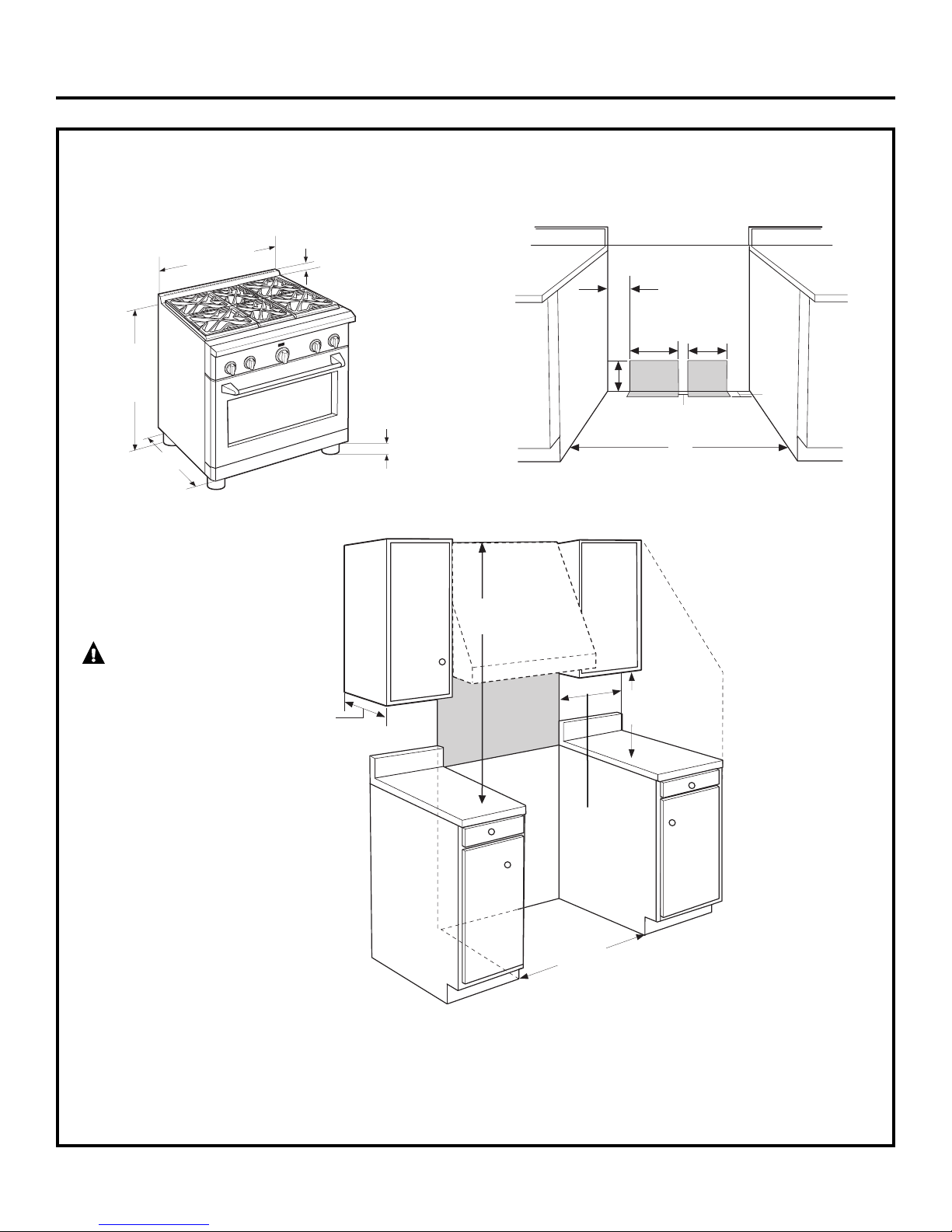
Design Information
CONTENTS
Design Information
Models Available......................................................................3
Backsplash Accessories ......................................................3
Product Dimensions and Clearances........................4-7
Tools and Materials Required .......................................... 8
Installation Preparation
Power Supply Locations ..............................................9, 10
MODELS AVAILABLE
These Monogram ranges are factory set for either
natural gas or LP gas. Order the model for your
installation situation.
48" Natural Gas Models:
ZDP484NG – 4 gas burners, grill and griddle
ZDP486NR – 6 gas burner
ZDP486ND – 6 gas burners and griddle
48" LP Gas Models:
ZDP484L
ZDP486LR – 6 gas burner
ZDP486LD – 6 gas burners and griddle
G – 4 gas burners, grill and griddle
s and grill
s and grill
Installation Instructions
Step 1, Remove Packaging ..............................................11
Step 2, Move Range Indoors ..........................................12
Step 3, Install Anti-Tip Device ........................................13
Step 4, Connect Range to Gas........................................14
Step 5, Connect Electrical ................................................14
Step 6, Roll Range into Position ....................................14
Step 7, Level the Range ....................................................15
Step 8, Replace Oven Doors............................................15
Step 9, Check Burners ........................................................16
Finalize Installation ..............................................................16
Installation Checklist ..........................................................16
Accessories..............................................................................17
Accessory Installation ................................................18–20
Gas Conversion ............................................................21-23
36" Natural Gas Models:
ZDP366N – 6 gas burners
ZDP364NR – 4 gas burners and grill
ZDP364ND – 4 gas burners and griddle
36" LP Gas Models:
ZDP366L – 6 gas burner
ZDP364LR – 4 gas burner
ZDP364LD – 4 gas burners and griddle
s
s and grill
30" Natural Gas Model: ZDP304N
30" LP Gas Model: ZDP304L
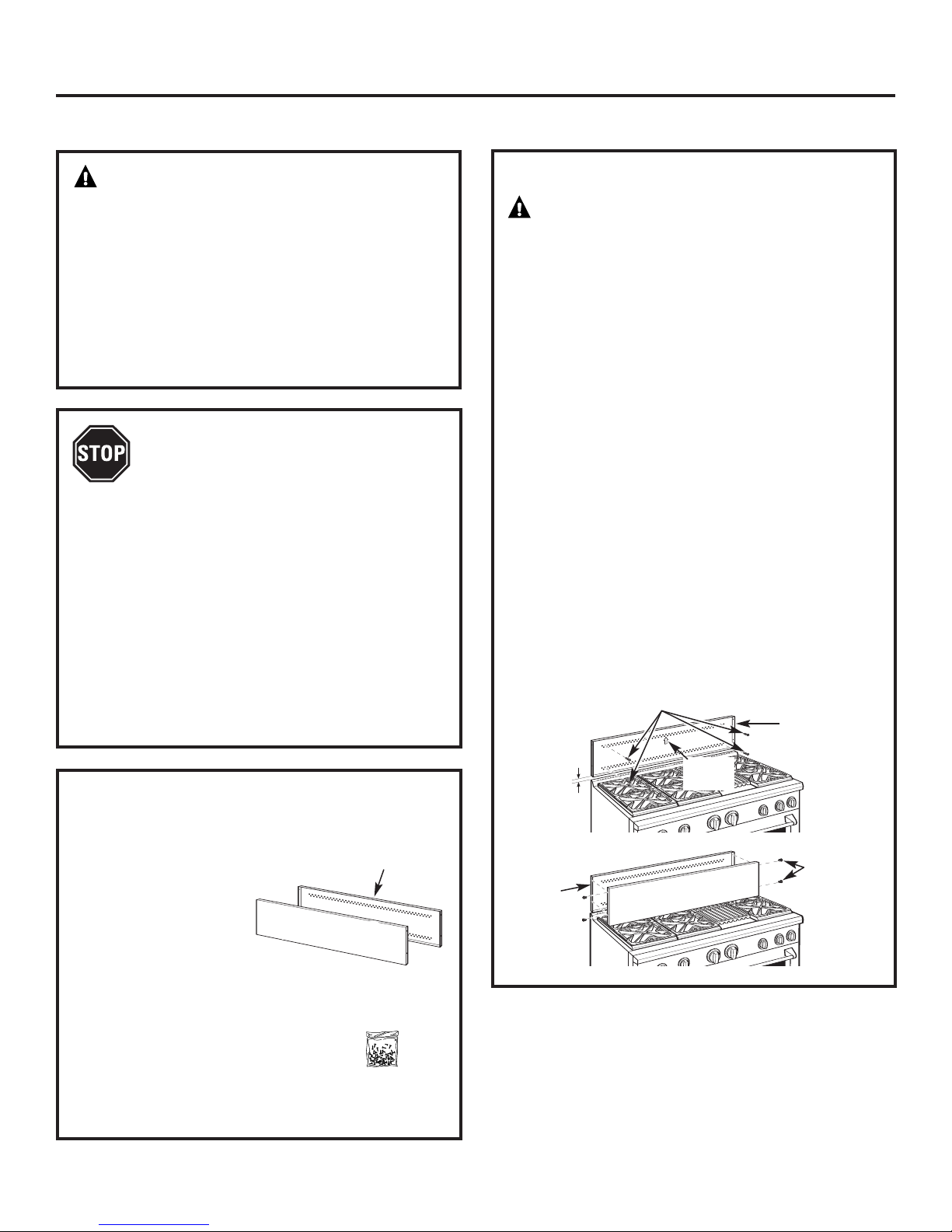
BACKSPLASH ACCESSORIES
All models require 12" minimum clearance to a
vertical combustible surface at the rear. If clearance
is less than 12”, the entire surface of the back wall
above and the full width of the range must be
protected by a backsplash. The backsplash must be
constructed of non-combustible material, such as
metal, ceramic tile, brick, marble or other stone.
Two Backsplash Accessories Available:
• The 12" high stainless steel backsplash accessory
is available. Use this backsplash in combination
with a custom, non-combustible backsplash built
beyond the 12” height
the backsplash accessory and the custom
backsplash must reach the bottom of a hood,
or when there is no hood, to 48” above the
cooking surface.
. The combined height of
An adjustable 30" to 36" high backsplash with
•
shelf is also available. This backsplash fills in the
space betw
bottom of the hood. The shelf is positioned so that
heat lamps from the bottom of a Monogram
ofessional hood are directed towards the shelf.
pr
een the top of the range and the
12" High Backsplash
ZX12B48PSS, for 48" wide ranges
ZX12B36PSS, for 36" wide ranges
ZX12B30PSS, for 30" wide ranges
30" to 36" Adjustable Height
Backsplash With Shelf
ZXADJB48PSS
ZXADJB36PSS
ZXADJB30PSS, for 30" wide ranges
, for 48" wide ranges
, for 36" wide ranges
3
Page 4
4
Design Information
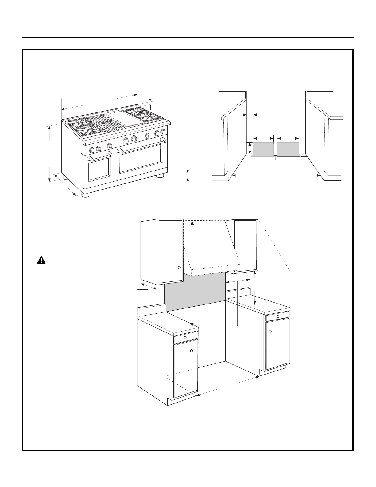
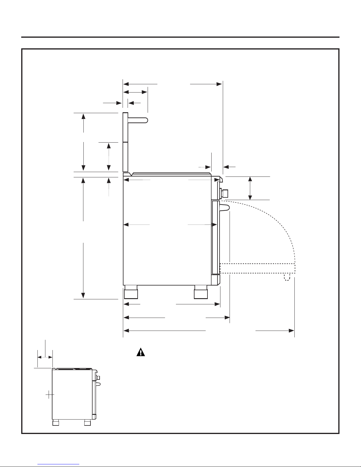
PRODUCT DIMENSIONS AND CLEARANCES
48" Range Models
Toekick/leg
Height
3-1/4”
to 4-3/4”
1”
35-1/4”
to
36-3/4”
Height
47-7/8” Width
28-1/4”
13”
Max.
12” Minimum
Each Side
48” Min.
ADDITIONAL CLEARANCES:
Allow 12" minimum clearance to an adjacent wall
on each side.
Working areas adjacent to the rangetop should have
18" minimum clearance between countertop and
the bottom of the wall cabinet.
12” Minimum
to Adjacent Wall
WARNING:
Installations without a hood require
48” minimum to combustibles.
A custom hood installation with
exposed horizontal combustible
surfaces must have an Auto-On
feature. Refer to hood installation
instructions for specific hood
clearances.
The surface of the entire back wall
above the range and below the
hood must be covered with a noncombustible material such as metal,
ceramic tile, brick, marble or other
stone.
Non-Combustible
Material
48”
8”
14”
2”
16”
Gas/
Electric
Electric
6-1/2”
2”
Universal Utility Locations
Depth
to Front
of Door
Countertop
to Cooking
Surface
48” Minimum
to Combustibles
18”
Min.
Page 5
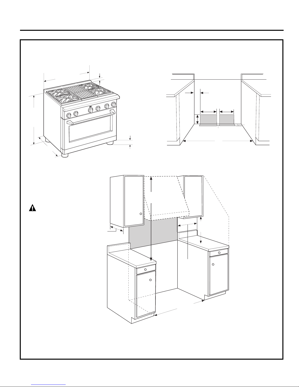
PRODUCT DIMENSIONS AND CLEARANCES
36" Range Models
Design Information
5
3-1/4”
to 4-3/4”
1”
35-1/4”
to
36-3/4”
Height
35-7/8” Width
28-1/4”
13”
Max.
36” Min.
ADDITIONAL CLEARANCES:
Allow 12" minimum clearance to an adjacent wall
on each side.
Working areas adjacent to the rangetop should have
18" minimum clearance between countertop and
the bottom of the wall cabinet.
WARNING:
Installations without a hood require
48” minimum to combustibles.
A custom hood installation with
exposed horizontal combustible
surfaces must have an Auto-On
feature. Refer to hood installation
instructions for specific hood
clearances.
The surface of the entire back wall
above the range and below the
hood must be covered with a noncombustible material such as metal,
ceramic tile, brick, marble or other
stone.
Non-Combustible
Material
36”
4-5/8”
13-3/8”
2”
11-3/8”
Gas/
Electric
Electric
6-1/2”
2”
Universal Utility Locations
12” Minimum
Each Side
12” Minimum
to Adjacent Wall
48” Minimum
to Combustibles
Depth
to Front
of Door
Toekick/leg
Height
Countertop
to Cooking
Surface
18”
Min.
Page 6
6
Design Information
PRODUCT DIMENSIONS AND CLEARANCES
30" Wide Range Models
13”
Max.
3-1/4”
to 4-3/4”
1”
35-1/4”
to
36-3/4”
Height
30” Min.
ADDITIONAL CLEARANCES:
Allow 12" minimum clearance to an adjacent wall
on each side.
Working areas adjacent to the rangetop should have
18" minimum clearance between countertop and
the bottom of the wall cabinet.
28-1/4”
30”
4-5/8”
11-3/8”
2”
7-3/8”
Gas/
Electric
Electric
6-1/2”
2”
WARNING:
Installations without a hood require
48” minimum to combustibles.
A custom hood installation with
exposed horizontal combustible
surfaces must have an Auto-On
feature. Refer to hood installation
instructions for specific hood
clearances.
The surface of the entire back wall
above the range and below the
hood must be covered with a noncombustible material such as metal,
ceramic tile, brick, marble or other
stone.
Universal Utility Locations
Non-Combustible
Material
12” Minimum
Each Side
12” Minimum
to Adjacent Wall
48” Minimum
to Combustibles
Depth
to Front
of Door
Toekick/leg
Height
29-7/8” Width
Countertop
to Cooking
Surface
18”
Min.
Page 7
Design Information
PRODUCT DIMENSIONS AND CLEARANCES
48", 36" and 30" Range Models
28-7/8”
10-1/2”
13/16”
To Front Edge
Optional
Backsplash
Accessories
12" Min. to combustibles or 0" to
a non-combustible material above
the cooking surface
30-36”
35-1/4”
to
36-3/4”
12”
1”
28-1/4” To
Beveled
Edge of Control
Panel Bullnose
27-1/2” To
Beveled Edge –
Maximum
Adjacent Cabinet
Depth for
Flush Installation
28-1/4”
To Front of Door
To Front of Handle
3-3/16”
Control Panel
Depth
7” Control Panel
Height
31-1/16”
48-1/4”
With Oven Door Open
0” Clearance
to a back or
side wall below
the cooking
surface
WARNING:
The 12” high stainless steel
backsplash accessor
installed in combination with a
custom non-combustible backsplash.
The finished backsplash must cov
the entire back wall up to the bottom
of a hood, or when ther
48” to combustibles.
y must be
er
e is no hood,
7
Page 8
Installation Information
WB28K10553 HIGH ALTITUDE KIT
For operation above 3,000 feet, order WB28K10553
Conversion Kit. This kit includes orifices for both LP
and Natural gas operation.
WB28K10554 DE-RATE KIT
(For a small kitchen environment.)
De-rate conversion kit for use with model
ZDP304N (natural gas only). This kit includes
orifices to reduce surface burner output
to 40,800 BTU’s.
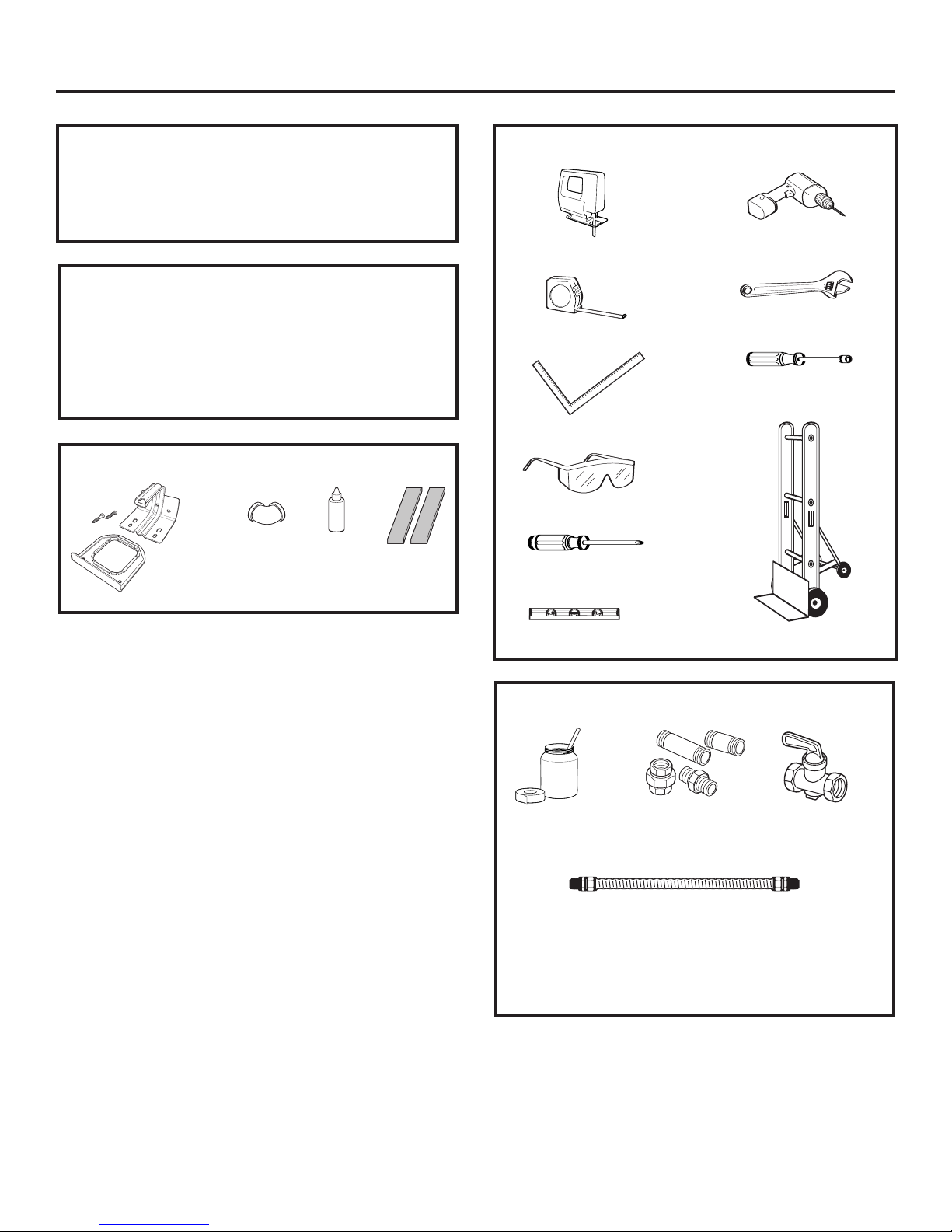
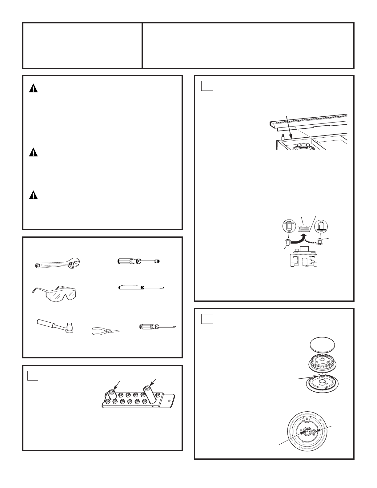
MATERIALS PROVIDED
Anti-Tip
Bracket, Brace
and Screws
1/2” Pipe
Elbow
Oven Rack
Lubricant
Runners
(to protect
flooring)
TOOLS REQUIRED
Saber Saw
Measuring Tape
Carpenter’s Square
Safety Glasses
Phillips #2 Screwdriver
rill and
D
Appropriate Bits
Adjustable Wrench
1/4” Driver or Wrench
Level
Hand Truck
MATERIALS REQUIRED (not provided)
Joint
Sealant
Pipe Fittings
5-foot maximum length, 5/8" O.D. CSA-approved flexible
metal gas supply
(3-foot maximum length in Massachusetts only)
NOTE: Pur
chase new flexible line; do not use
eviously used flexible gas line.
pr
Shut Off Valve
8
Page 9
Installation Preparation
POWER SUPPLY LOCATIONS
Gas Supply:
•The natural gas models are designed to operate
at 5" water column pressure. For proper operation,
the pressure of the natural gas supplied to the
regulator must be between 7" and 13" water
column.
•The LP models are designed to operate at 10"
water column pressure. For proper operation,
the pressure of the LP gas supplied to
the regulator must be between 11"
and 13" water column.
•A 1/2" elbow is provided for connection
to the range gas inlet, located at the rear
and near the floor.
•Locate the pipe stub on the back wall or floor
as illustrated in “Dimensions and Clearances.”
Use 5-foot maximum length, 5/8" O.D. flexible
gas supply line (3-foot in Massachusetts).
•Install a manual shut-off valve in the gas line
(not provided), in an easily accessible location.
Make sure the homeowner knows where
and how to shut off the gas supply to the range.
Electric Supply:
These ranges must be supplied with 208/240 volt,
60 Hz., and connected to an individual, properly
grounded branch circuit protected by a circuit
breaker or time delay fuse (50 amp for 48" ranges,
30 amp for 36" and 30" ranges). The receptacle
must be a NEMA 14-50R device to accept the
4-prong plug supplied with the range.
If the electrical service provided does not meet
the above specifications, it is recommended that
a licensed electrician install an approved outlet.
Locate the electric supply as illustrated
•
in “Dimensions and Clearances.”
WARNING
The range is equipped for use with an electrical
supply which uses a separate gr
(4 wire system).
If this range must be connected to an electrical
system which utilizes a single conductor for ground
and neutral (3 wire system), the grounding jumper
at the terminal block must be connected.
The gr
of the terminal block.
ounding jumper is located to the right
ounding conductor
The access plate
is on the back
of the range.
See 3-wir
9
er cord installation on the next page.
e pow
Page 10
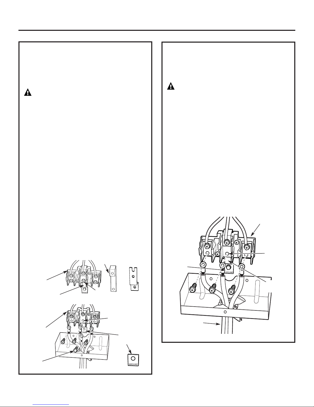
Installation Preparation
4-WIRE POWER CORD INSTALLATION
NOTE: A 4-wire cord is connected to the range
at the factory. Use the following steps to change
an existing installation from a 3-wire cord back
to a 4-wire cord.
WARNING
The neutral wire of the supply circuit must
be connected to the neutral terminal located
in the lower center of the terminal block.
The power leads must be connected
to the lower left and the lower right
terminals of the terminal block. The 4th
grounding lead must be connected to
the frame of the range with the ground
plate and the ground screw.
•Remove the 3 lower terminal screws from
the terminal block. Remov
and ground plate and r
•
Remov
THE GR
•Insert the one ground scr
ground wire terminal ring, through the ground
plate and into the frame of the range.
•Insert the 3 terminal screws (removed earlier)
thr
into the low
Be certain that the center wire (white/neutral)
is connected to the center low
of the terminal block. Tighten scr
into the terminal block.
Before
e the ground strap. DO
OUND STRAP OR ANY SCREWS.
ough each power cord terminal ring and
er terminals of the terminal block.
Terminal
Block
ound Strap
Gr
e the gr
etain them.
ew into the power cord
Neutral
Terminal
ound screw
NOT DISCARD
er position
ews securely
Ground Strap
or
3-WIRE POWER CORD INSTALLATION
NOTE: A 4-wire cord is connected to the range
at the factory. Use the following steps to change
the range to a 3-wire cord.
WARNING
The neutral or ground wire of the power cord
must be connected to the neutral terminal located
in the center of the terminal block. The power leads
must be connected to the lower left and the lower
right terminals of the terminal block.
Remove the ground strap (located at the right
•
side of the terminal block) and connect between
the center low
to the frame of the range.
•Remove the 3 low
the terminal block. Insert the 3 terminal screws
through each power cord terminal ring and
into the lower terminals
Be certain that the center wire (white/neutral)
is connected to the center lower position
of the terminal block. Tighten scr
into the terminal block.
NOT remove the ground strap connection.
DO
Ground
Plate
er portion of the terminal block
er terminal screws from
of the terminal block.
ews securely
Terminal Block
(appearance
may vary)
Neutral
Terminal
ound
Gr
Strap
er
t
Af
erminal
T
Block
Ground
Screw
Neutral T
Ground Plate
(grounding to
range)
er
minal
Power Cord
10
Page 11
Installation
STEP 1
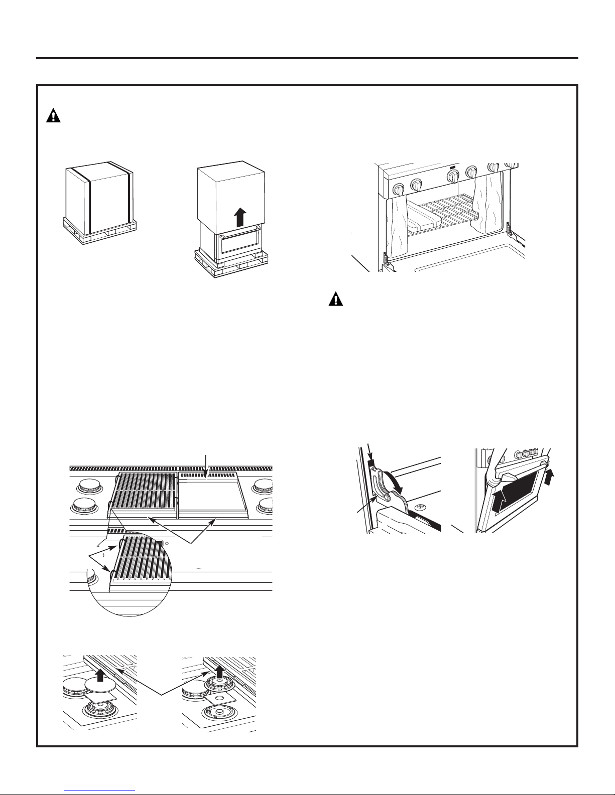
REMOVE PACKAGING
CAUTION
Stand clear. The ends of the cut metal banding may
snap toward you.
•Cut the metal banding. Lift the carton straight up.
•Locate the two runner strips from the top
of the packaging. These strips will be used to
protect the k
•Remove corner posts. Dispose of packaging
materials.
•Remove grill/griddle covers, grill grate and burner
grates.
•Lift out cast-iron griddle flue cover, grease troughs
and pads.
•Cut the ties holding the grill grate to the grill frame.
itchen floor during installation.
Griddle Flue Cover
• Open oven door(s) and remove packaging.
Remove shelf holding broiler pan, tape, literature
package, shelf lubricant and probe.
CAUTION
Doors and passageways leading to the installation
location require at least 32" opening. If the opening
is less than 32", the oven door(s) and control knobs
must be remov
REMOVE THE OVEN DOOR(S) ONLY IF NECESSARY to
move the range through the doorways. To prevent
damage t
necessary to pad the corners beneath the straps
on the hand-truck.
Slot
ed.
o the sides of the range, it will be
ies
T
Lift off burner caps and r
•
then lift off burner heads and remove foam pad.
Remove Foam Pads
Grease Troughs
e foam pad,
emov
Hinge
Lock
To remove the oven door(s):
• Fully open the door
• Each hinge has a hinge latch. Close the hinge
latch down against the door frame.
• Firmly grasp the door at the top sides.
• Close the door to the near
• Lift the door up and pull straight out
• Remove the control knobs by pulling them
straight out
.
.
tical position.
er
-v
11
.
Page 12
Runners
To Support
Leveling Legs
Range
Opening
Installation Preparation
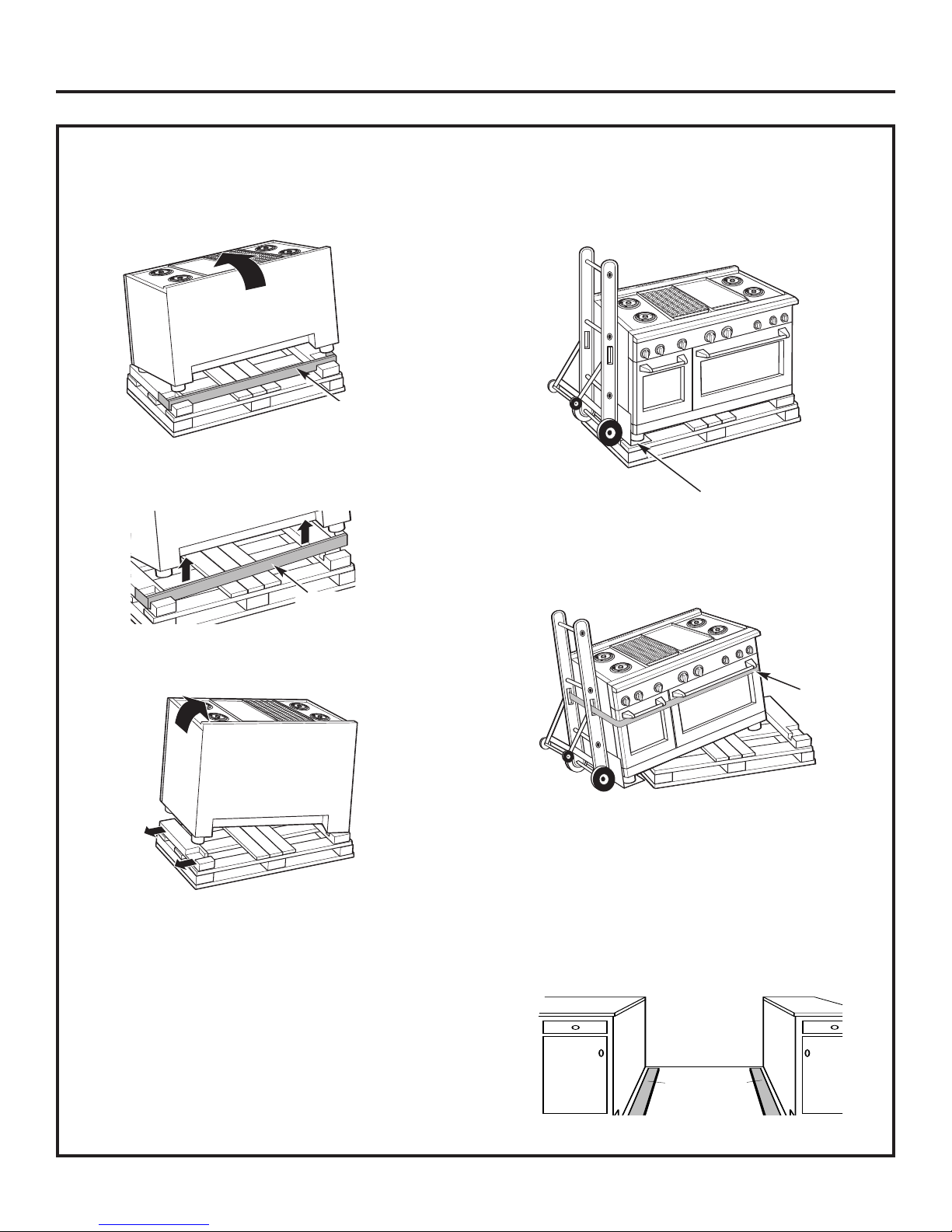
STEP 2
MOVE THE RANGE INDOORS
1 Tilt the range forward on the skid.
2 Lift the toek
ick out of the foam base.
Toekick
Toekick
4 Slide the blade of the hand-truck beneath
the front and back legs.
Insert Blade Under
the Range Legs
IMP
ORTANT
:
Place the hand-tr
uck straps below
the oven door handles.
5 Tilt the range to lower the hand-truck wheels
off the skid.
3 Tilt the range to one side and remove the foam block.
e the range indoor
6 Mov
s. Position the range
in front of the installation location.
7 Place the appliance runners on the floor
at the left and right sides of the opening.
unners provide a surface for rolling
The r
the range into the final position and will protect
the floor finish. The runners must be removed
e leveling the range.
befor
Range
Opening
Runners
for Rolling
the Range
into Position
12
Hand-Truck
Straps Below
Oven Door
Handles
Page 13
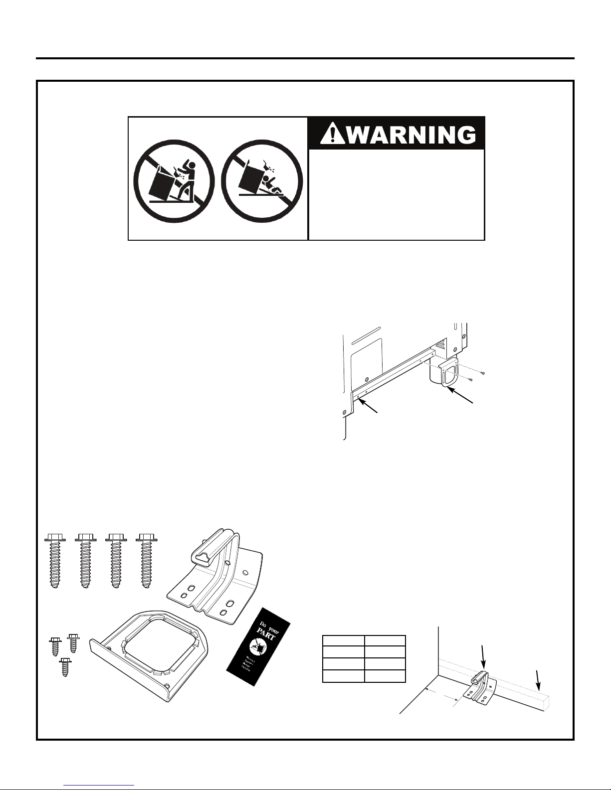
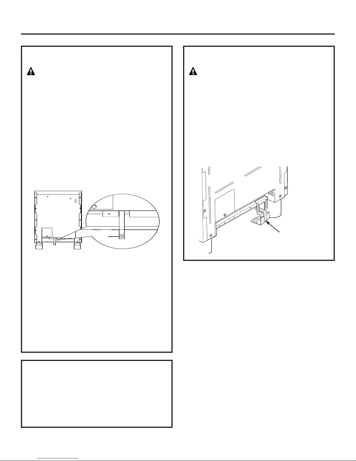
INSTALL ANTI-TIP DEVICE
STEP 3
Installation
13
Anti-Tip Parts Provided
• Attach the Anti-Tip Brace onto the bottom
of the range in the recessed area. Install 2 hex
screws (provided) through the brace and into
the range.
NOTE: This Anti-Tip device may be installed on the
opposite side of the range.
Alternate Brace
Position
Hex Screws
Anti-Tip Brace
• Measure and mark Dimension A (see table below)
from the left (or right) side of the installation
location. If the countertop has an overhang,
add that dimension to Dimension A.
• Place the Anti-Tip Bracket against the floor
and back wall at the marked location. Mark screw
holes for fastening the bracket to the wall sole plate
and the floor.
• Drill 1/8" pilot holes at a 20° angle.
• Secure the bracket to the wall and/or floor with
at least 2 wood screws (provided).
For Concrete or Cement Construction: You must
use appropriate fastening hardware (not provided).
Anti-Tip Bracket
Anti-Tip Brace
4 Wood Screws
AHAM Anti-Tip
Safety Brochure
3 Hex Head Screws
(2 required, 1 extra)
To reduce the risk of tipping the range, the range
must be secured by a properly installed anti-tip bracket.
See installation instructions shipped with the bracket
for complete details before attempting to install.
To check if the bracket is installed and engaged properly,
carefully tip the range forward. The bracket should stop
the range within 4 inches. If it does not, the bracket must
be reinstalled.
If the range is pulled from the wall for any reason,
always repeat this procedure to verify the range
is properly secured by the anti-tip bracket.
If your range has no anti-tip bracket, call 1.800.626.8774
to receive one at no cost.
If the Anti-Tip device supplied with the range does not fit this
application, use the universal Anti-Tip device WB2X7909.
Read the AHAM Anti-Tip Safety Brochure packed
with the bracket.
Anti-Tip Bracket
A
Wall Sole Plate
Range A
30” 5-1/16”
36” 5-1/16”
48” 8-1/4”
• All ranges can tip.
• BURNS or other SERIOUS INJURIES
can result.
• INSTALL and CHECK the ANTI-TIP
bracket following these instructions.
Page 14
Installation
STEP 4
CONNECT RANGE TO GAS
WARNING
Do not use a flame to check for gas leaks.
Assure that gas supply is turned off
at the shut-off valve:
• Apply pipe thread sealant to the gas inlet located
at the back of the range. Install the 1/2" pipe
elbow (provided) to the gas inlet.
• Connect 5/8" O.D. flexible metal connector
to gas inlet. Connect the other end of the flexible
connector to the house gas supply.
Turn on the gas and check for leaks:
•
– Use a liquid leak detector at all joints
and connections in the system.
STEP 6
ROLL RANGE INTO POSITION
WARNING
The Anti-Tip Bracket must be properly installed
to prevent tipping of the range. Failure to do so
can cause serious damage or injury.
• Check to be sure the appliance runners are
beneath the wheels.
• The range is shipped with the wheels in the down
position. Carefully roll the range into position,
being car
cord and flexible gas tubing.
emove the runners beneath the range.
• R
eful not to entangle or pinch the power
Gas
Inlet
IMPORTANT: Disconnect the range and the
individual shut-off valve from the gas supply piping
system during any pressure testing of that system
at test pr
range fr
the individual manual shut-off valve to the range
during any pressure testing of the gas supply piping
system at test pr
1/2 psig.
NO
valve located on top of the range, beneath the rear
vent. This shut-off valve is to be used in the event
that ser
STEP 5
• Plug power cord into properly grounded
receptacle.
• Verify that power is connected by opening
the oven door or press the button on the left side
of the control panel to illuminate the accent
lighting.
essures greater than 1/2 psig. Isolate the
om the gas supply piping system by closing
es equal to or less than
essur
TE:
This range is equipped with a gas shut
ed in the future.
vice is r
equir
CONNECT ELECTRICAL
-off
Be sure Anti-Tip
Bracket is engaged
with the brace
on the range.
14
Page 15
Installation
STEP 7
LEVEL THE RANGE
WARNING
The range must be level and be supported
by the legs—not the wheels. The range could move
if the wheels make contact with the floor. Be sure all
legs make contact with the floor in any installation.
•All legs must be leveled after the product is
installed.
•Check to be sure the adjoining cabinets/
countertops are level, front to back and left
to right across the opening of the range.
•Measure the distance from the floor to the top
of the countertop in the left and right rear corners.
•Adjust the height of the range to countertop height
or higher
IMP
at countertop height or higher. DO NOT INSTALL
THE RANGE LOWER THAN ADJACENT COUNTERTOP
HEIGHT
regardless of countertop height.
FRONT LEG AD
•Slide front cylinders up to adjust front leveling
legs. Be car
•A leveling leg wrench is supplied. Reach under
the fr
and remove a thumb screw, then slide wrench out
of the slot.
Thumb Screw
.
ORTANT
:
This range should alw
. The range must be supported by all 4 legs,
JUSTMENT
eful not to damage cylinder.
ont of the range near the right side. Locate
ays be installed
STEP 7
REAR LEG ADJUSTMENT
•Remove two screws from rear vent trim. Slide vent
trim forward, then lift up to remove.
•Find the two rear leg extension rods. Use a 1/4"
driver or wrench to adjust the left or right rear legs.
•Replace the rear vent trim using the original screws.
STEP 8
Skip this step if oven doors are in place.
IMPORTANT:
To replace the oven doors:
•Firmly grasp the door at the top sides.
This is critical.
•Approach the range with the door angled
in a v
•Guide the hinges into the slots.
•Push the door in firmly while opening.
•Once in position, open the door completely.
Push the hinge locks back in and toward
the front frame.
LEVEL THE RANGE (cont.)
Rear Vent Trim
Rear Leg
Extension Rod
REPLACE OVEN DOOR(S)
Do not lift the door by the handle.
ertical
position.
•Use the supplied wrench to turn the front leveling
urn clock
legs. T
wheels. Turn counterclockwise to lower the legs.
•Be sure to return the wrench to its storage slot
for future use.
wise to raise the range abov
Slide leg
cylinder up.
e the
CAUTION: Take care when replacing
the ov
locked, the hinge may snap back and separate.
If the hinge separates, you must apply pr
(possibly with your foot) to pr
and then engage the hinge latch.
en door
15
s. If the hinge latch is not secur
ess it back together
ely
essure
Page 16
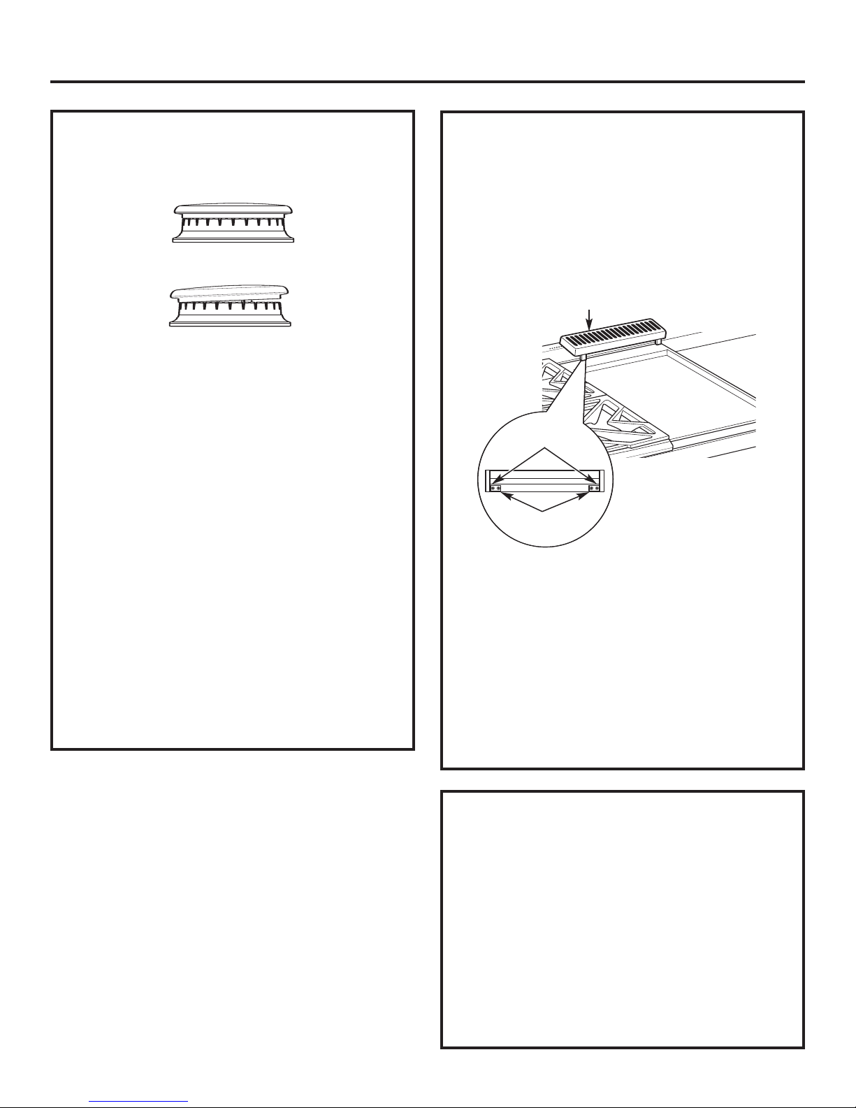
Installation
STEP 9
Check to be sure that burner heads and caps
are securely seated.
•Check for proper ignition:
– Push in one control knob and turn to LITE
position.
– The igniter will spark and the burner will light;
the igniter will cease spark
is lit.
– First test may require some time, while air
is flushed out of the gas line.
– Turn knob to OFF.
– Repeat the procedure for each burner.
IMPORTANT: If the igniter electrodes continue
to spark after the burners are lit, check that
each burner component is assembled properly.
Refer to the Owner’s Manual.
•Burner flames should be blue and stable with no
yellow tips, excessive noise or lifting of the flame
om the burner. If any of these conditions exist,
fr
check that the burner ports are not blocked.
If one of these conditions continues, call for
service.
CHECK BURNERS
Burner Cap Properly Seated
Burner Cap Not Properly Seated
ing when the burner
FINALIZE INSTALLATION
Place the burner grates over the burners.
The grates should be seated and should not rock.
The griddle is secured with screws. It is designed
to be stationary and should not be removed.
The griddle has two leveling screws beneath
the rear flue cover that can be used to adjust
to the desired slope.
Griddle Flue Cover
Leveling Screws
Clamping Screws
The tw
securing the griddle in place. Loosen these two
screws before leveling. Do not remove these two
screws.
The two outer scr
remove these two screws. They can be turned to
level the griddle or to provide a forward slope to
help grease and oils drain away from the food
being cooked.
After leveling the griddle, hand-tighten
the clamping screws; do not over-tighten.
o inner screws are clamping scr
ews are lev
eling scr
ews for
ews. Do not
INSTALLATION CHECKLIST
❑ Make sure all controls are left in the OFF position.
e the flow of combustion and ventilation
❑ Mak
❑ Recheck Steps:
NOTE:
of the control panel and is visible when the oven door
is opened. The model and serial number is behind
the left knob and is visible when the knob is pulled off
16
e sur
air to the range is unobstructed.
ything in this
er
e ev
e sur
Double check t
manual has been completed. Rechecking steps
will ensure safe use of the range.
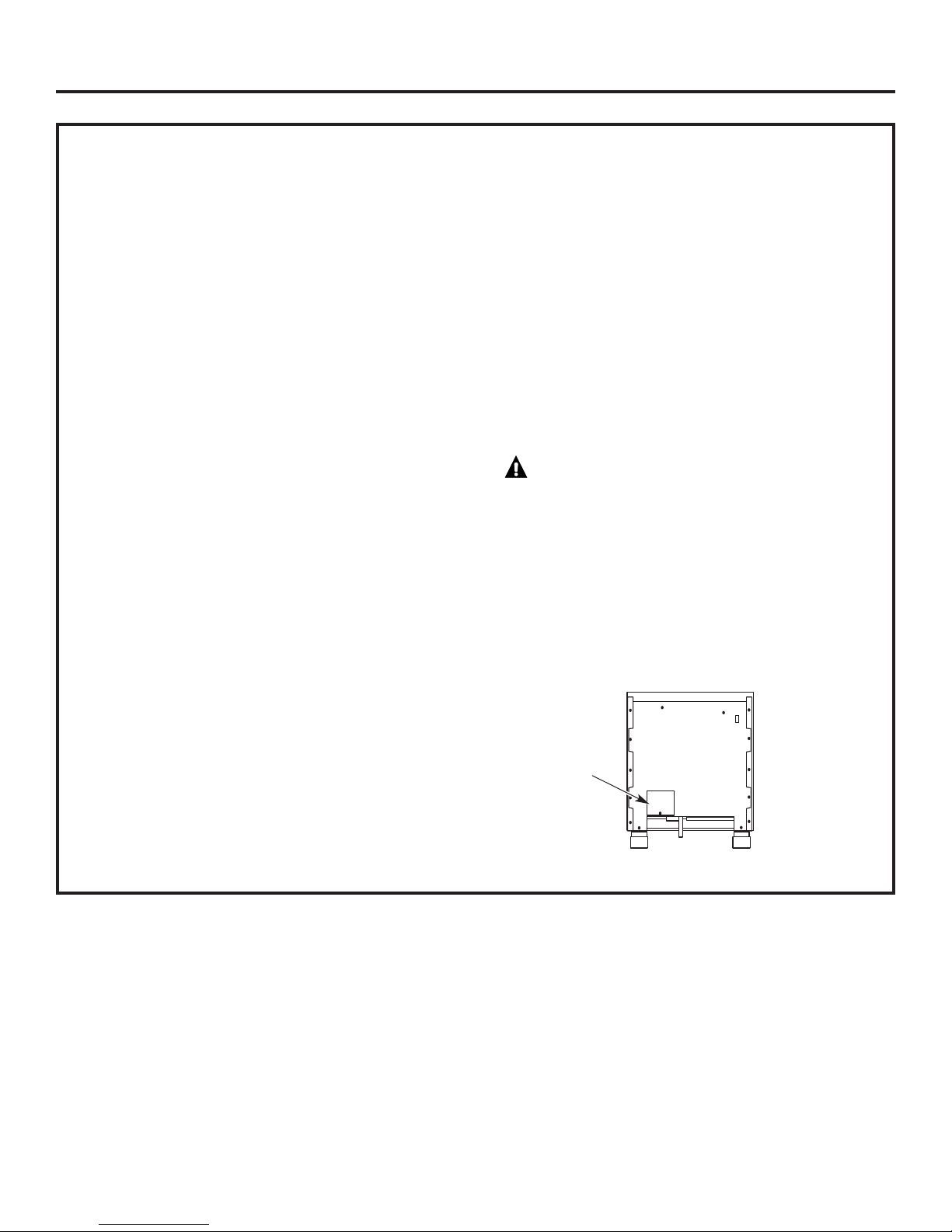
The rating plate is located on the bottom
o mak
.
Page 17
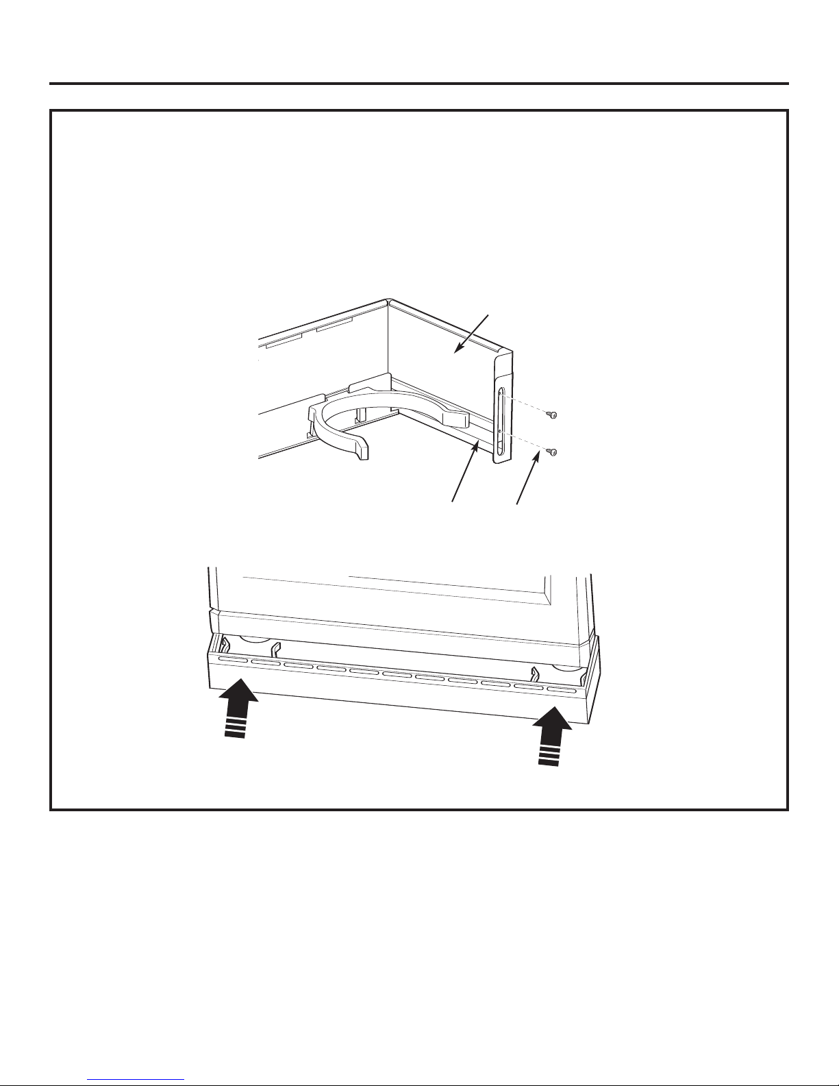
ACCESSORIES—TOEKICK (provided)
Installation
•Install the toekick after the range has been leveled.
•Measure the distance between the floor
and the bottom of range.
•Loosen the two screws on each end. Adjust
the toekick height by sliding the upper and lower
pieces apart to 1/8" less than the measured height.
•Secure the top and bottom sections by tightening
the 2 screws on each end.
•Push toekick against range leg until clip snaps
to legs.
NOTE: Be sure the toekick snaps securely to the leg.
Top of
Toekick
Bottom
of Toekick
Screw
Push
Push
17
Page 18
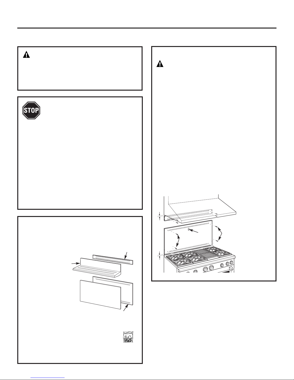
ZX12B30PSS, ZX12B36PSS, ZX12B48PSS Accessory Installation
OPTIONAL ACCESSORIES—12" HIGH BACKSPLASH
WARNING:
To prevent ignition of combustible materials,
the entire back wall above the range must
be protected by a backsplash constructed
of non-combustible material.
This stainless steel backsplash accessory
must be installed in combination with a custom,
non-combustible backsplash built beyond
the 12" height of the backsplash.
BEFORE YOU BEGIN
Read these instructions completely
and carefully.
IMPORTANT: Save these instructions for local
inspector’s use.
IMPOR
AND ORDINANCES
NO
instructions with the Consumer.
NOTE TO CONSUMER: Keep these instructions
with your Owner’s Manual for f
This kit pr
backsplash for 30", 36" or 48" Monogram
Professional Ranges and Rangetops.
TOOLS AND MATERIALS REQUIRED
•
• T-15 and #2 Phillips screwdrivers
• Drill with 3/32" and 9/64" bits
•
• Level
• Pencil
TANT: OBSERVE ALL GOVERNING CODES
.
TE TO INSTALLER: Be sure to leave these
uture refer
ovides for the installation of a 12" high
es to pr
Glov
Safety glasses
otect against sharp edges
Wall Support
Panel
Cover Panel
ence.
INSTALL 12" BACKSPLASH
WARNING: This backsplash must
be securely fastened to the wall. Failure to do
so could result in damage or personal injury.
• Install and level the range or rangetop and the
range hood according to the installation
instructions.
• Remove the backsplash packaging and
protective film.
• Use a level to pencil a horizontal line on the wall,
1/8" above the range or rangetop. The 1/8" gap
allows the cover panel to overlap the wall support
panel.
• Locate wall studs on each side. Where studs are not
ailable, plan to use wall anchors (not provided).
av
• Align the wall support panel on the marked
horizontal line and centered left to right
• The wall support panel must be secured to the wall
at all 4 corner
anchors (not provided) to secure the support panel
to the wall.
• Place the cover panel over the wall support
panel and secure with Torx screws (provided).
Install 2 screws on each side.
1/8″
all
W
Support
Panel
s. Use wood screws (provided) or wall
Install 4 Wood
Screws
Center
Arrow
Cover Panel
.
Wall Support
Panel
Install T-15
Screws
This Kit Includes
• Wall support panel
er panel
Cov
•
dware package with
Har
•
x 15 #8
or
– 5 Stainless S
self-tapping screws
– 5 Phillips #2 pan head w
#10 screws
teel T
ood
dwar
Har
Package
e
18
Page 19
ZXADJB30PSS, ZXADJB36PSS, ZXADJB48PSS Accessory Installation
ACCESSORIES—30" TO 36" ADJUSTABLE BACKSPLASH (not included)
WARNING:
To prevent ignition of combustible materials,
the entire back wall above the range must
be protected by a backsplash constructed
of non-combustible material.
BEFORE YOU BEGIN
Read these instructions completely
and carefully.
IMPORTANT: Save these instructions for local
inspector’s use.
IMPORTANT: OBSERVE ALL GOVERNING CODES
AND ORDINANCES
TE TO INSTALLER
NO
instructions with the Consumer.
NOTE T
with your Owner’s Manual for future reference.
• This backsplash adjusts to fit the space between
• Maximum shelf load-bearing weight is 40 lbs.
O CONSUMER: Keep these instructions
op of the range and the bottom of the hood,
the t
from 30" Min. to 36" Max. height.
.
: Be sure to leave these
INSTALL THE WALL SUPPORT PANELS
W
ARNING:
must be securely fastened to the wall. Failure to
do so could result in damage or personal injury.
IMPORTANT: This backsplash is designed to cover the wall
between the bottom of the hood and the top of the range.
The vent hood should be installed over the rangetop or
range before installing this backsplash.
• Install and level the Range/Rangetop according
to the product installation instructions.
• Remove backsplash packaging and protective film.
• Locate wall studs on each side. Where studs are not
available, plan to use wall anchors (not provided).
• Use a level to pencil 2 horizontal lines on the wall,
one 1/8" below the vent hood and the other 1/8" above
the Range/Rangetop. This 1/8" space allows the cover
panels to overlap the wall supports.
• Secure the top wall support panel to the wall with 4 wood
screws, through the outermost studs.
• Use 4 wood screws to secure the bottom wall support
panel. The center slot should be positioned at the top.
The gap between the top and bottom support panels
will be covered by the top cover with shelf.
1/8″
The wall support panels
Secure the top
panel to the wall
with 4 wood
screws
TOOLS AND MATERIALS REQUIRED
• Gloves to protect against sharp edges
• T-15 and #2 Phillips screwdrivers
• Drill with 3/32" and 9/64" bits
Safety glasses
•
• Level
• Pencil
Top Cover
with Shelf
This Kit Includes
all suppor
op w
T
•
•
Bottom w
• Top cover with shelf
• Bottom cover
e package with
ar
dw
Har
•
– 9 Stainless Steel Torx 15 #8
self-tapping scr
– 9 Phillips #2 pan head w
– 3 Stainless Steel #2 truss head
#10 screws (for alternate
installation method)
t
all support
ews
Bottom Cover
Bottom Wall Support
ood #10 scr
Top Wall
Support
ews
Hardware
Package
19
1/8″
Center
Wood Screws
Arrow
Wood
Screws
Secure
the bottom panel
to the wall with
4 wood screws
Page 20
ZXADJB30PSS, ZXADJB36PSS, ZXADJB48PSS Accessory Installation
INSTALL COVER PANELS
See alternate method if side access is blocked.
• Hold the bottom cover over the bottom support
while driving one screw (provided) into each side.
• Place the top cover with shelf over the top wall
support. If you have access to the sides, secure
the panel with two screws on each side.
• Secure the top cover with shelf to the top
support with screws through the front of the panel,
at the top corners. Use one screw on each side.
Install
Cover Panel
Install
Screw
Screw
INSTALL COVER PANELS (cont.)
ALTERNATE METHOD: When side access is blocked
• Install bottom cover over the bottom support while
driving one screw into each side.
• Hold top cover in place while marking screw
locations, just below shelf support and onto bottom
cover.
• Remove the shelf and drill a 9/64" diameter
hole in the pencil-marked locations.
• Mount the top cover over the top support
and secure the front cover with screws through
the drilled holes on each side.
• Install screws through each top corner.
Mark Scr
for Alternate Method
ew Locations
Install Corner Screws
Install Screw
on Each Side
Install Screw in Top Corner on Each Side
Shelf
20
Page 21
DOWN
FOR OFF
N
AT
LP
LP
NAT
L
P
N
AT
N
AT
L
P
Installation Convert Natural Gas to LP Gas Operation
Instructions Convert LP Gas to Natural Gas Operation
2
WARNING: This conversion must
be performed by a qualified installer or gas supplier
in accordance with the manufacturer’s instructions
and all codes and requirements of the authority having
jurisdiction. Failure to follow instructions could result
in serious injury or property damage. The qualified
agency performing this work assumes responsibility
for the conversion.
WARNING: The rangetop, as shipped from
the factory, is set for use with its intended gas. If you
wish to use your rangetop with the alternate gas, you
must first replace the orifices and convert the pressure
regulator.
WARNING: The following adjustments must
be made before turning on the burner. Failure to do so
essure regulator
esult in serious injury. Be sur
could r
has been converted as described in Step 2.
TOOLS YOU NEEDED FOR CONVERSION
e pr
CONVERT THE REGULATOR
Disconnect all electrical power at the main circuit
breaker or fuse box.
A. Remove the rear vent
trim (on ranges only)
to access the
regulator. The
Rangetop regulator is
on the left bottom
corner.
B. Shut off the gas supply by closing the manual shut-off
valve in the unit or at the wall.
C.
Convert the pressure regulator:
• Unscrew the cap with plunger.
• Place your thumb against flat side of the plunger and
press down to snap the plunger out of the cap.
• Carefully look at the plunger to locate the NAT
or LP position.
• Turn the
plunger
over so
that the
desired gas
is showing
near the
bottom.
Range Regulator
NAT. Position
Cap
Gasket
Plunger
LP Position
Crescent Wrench
Safety Glasses
1/2” Deepwell
Socket W
1
ORIFICE HOLDER
ench
r
Small Pliers
1/4” and 7mm Nutdrivers
Small Flat-Head Screwdriver
(2 to 2.4 mm or 3/32” tip size,
60 mm long)
Griddle
Orifice
The range orifice holder
is located behind the front
access panel at the bottom
of the range.
The rangetop orifice holder
Burner Orifices
is located inside the range insulation cover.
. Use only the orifices
Additional orifices may be pr
specified in the instructions for your range or rangetop.
esent
Philips
Scr
ewdriver
Grill
Orifice
• Snap the plunger back into the cap
• Screw the cap back onto the regulator.
3
CHANGE BURNER ORIFICES
INSTALLATION TIP: First remove all
orifices and then star
t replacing them.
This will help to prevent the possibility
that some may not be replaced.
A. Remove the burner grates,
burner caps and burner heads.
B. Loosen the top burner
orifices using a 7 mm
nut driver. Use small
efully lift out the orifices.
s to car
plier
The main orifice is located
low in the center of the
burner, while the simmer
orifice is located higher
beside the center
of the burner
.
21
Pressure Regulator
.
Burner Cap
Burner
Head
Spark
Igniter
Burner Base
Simmer
Orifice
Main
Orifice
Page 22

Installation Instructions for Gas Conversion
3
CHANGE BURNER ORIFICES (cont.)
IMPORTANT: Find your model number below. Read
each orifice label to identify and install them in the
exact locations shown.
ZDP304 SIMMER ORIFICES
A 34SL or 51SN orifice
will be used on all burners.
ZDP304 MAIN ORIFICES
Use a 108XL
or 190XN orifice
A 84XL or
126HXN orifice
will be used
on these three
burners.
for the right
front burner.
4
CHANGE GRILL ORIFICE
Locate the 1–1/2” long Grill orifice.
Select for your gas type. LP
—
.047, NAT—.067
A. Remove the grill cover,
grates and grate frame. Lift
the radiant baffle straight
up and off.
B. Remov
e the 2 hex
head screws from
the top of the igniter.
• Remov
e one scr
ew
Remove 2
hex head
screws
from each side of
the burner surround.
• Lift out the surround.
(if present)
Surround
Screws
ZDP364, ZDP366, ZDP484, ZDP486
SIMMER
ORIFICES
MAIN
ORIFICES
A. Return the unused orifices to the holder. Reattach
the holder and the instruction sheet with screw
in the original storage location.
B. Replace the burner heads, caps and top grates
On range models, replace rear vent trim.
A 34SL or 51SN orifice
will be used on all
burners.
Use 108XL or
190XN orifices
for all burner
s.
C. Carefully push the
igniter aside and
Burner
Surround
Igniter
under
the burner.
Do not pull or pinch
the wire.
Remove 4 burner
Burner
Assembly
attachment screws,
2 at the fr
at the back
ont and 2
. Slide the
burner assembly
toward the back and
out of the gas inlet
D. Use a 1/2" deep well
.
Front of Range
socket to remove
eplace the orifice .
and r
Reverse these
steps to re-assemble
the grill. Be sure to
.
place the unused
orifice in the holder
for possible f
uture use.
22
Page 23

Installation Instructions for Gas Conversion
5
CHANGE GRIDDLE ORIFICE
Locate the 3/4” long Griddle orifice.
Select for your gas type. LP
—
.047, NAT—.076
A. Lift off
the griddle flue
cover. Remove
the 2 inside
clamping
Griddle Flue Cover
A
screws.
B. Use a pad or
piece of
carton to
protect
the adjacent
Leveling Screws
surface. Slide
the griddle
ard
tow
Clamping Screws
the rear
and out of
the hold-down tabs along
B
the bottom.
C. CAREFULLY lift and hold
the griddle. A thermostat
y is routed through
capillar
a clip. Gently lift the griddle
to one side and slip the
y out of the clip.
capillar
D. Lay the griddle
C
on the padded surface.
Do not disconnect or pull
on the capillary.
E. Remov
e the 2 burner
hold-down screws
at the rear of the burner.
• Pull the burner straight
back tow
ard the rear
D
and out of the gas inlet.
F. Use a 1/2" deep well socket
emove and replace
to r
the orifice.
(if present)
NOTE: Remove
the 2 screws
positioned on
the inside only.
Do not remove
the outermost
screws—they
are for leveling.
Capillary
6
ADJUST BURNER FLAMES
Normally, burners do not need further adjustment.
Make adjustments only when necessary.
A.
Turn on the gas. Plug in electrical cord.
B. Turn all burners on highest setting and check
the flames. They should be blue in color. When
using LP gas, the flames may have some yellow
tipping at the ends of the flame. Foreign particles
in the gas line may cause an orange flame at first,
but this will soon disappear.
C. Turn the burner knob to “LO” while observing the
flame.
Adjust the setting of the upper row of flames using
the valve bypass screw as follows:
Adjustments must be made with two other burners
in operation on a medium setting. This prevents
the upper row of flames from being set too low,
resulting in the flame being extinguished when
other burner
s are turned on.
D. To adjust the flame, remove the knobs. Insert a small
flat-blade screwdriver into the hole in the center
of the valve stem to engage screw.
• If the flames are too small or flutter,
turn the screw counterclockwise.
E
Back of Range
F
Reverse these steps to re-assemble the griddle. Push excess
capillary back into the entry hole. Route the thermostat
capillary so it is held by the clip. Place the unused orifice in
the holder for possible future use.
Once the conversion is complete and checked, fill out the conversion label and affix the label near the rating label. For ranges,
place the label beneath the contr
ol panel. For rangetops, place the label on the bottom of the unit
Front of Range
• If the flames are too large, turn the screw
clockwise.
E. Make the adjustment by slowly turning the screw
until flame appearance is correct.
.
23
Page 24

Consignes d’installation
AVANT DE COMMENCER
Lisez attentivement l’ensemble des consignes.
•
IMPORTANT — Conservez ces consignes,
elles peuvent vous être utiles pour toute
inspection de votre installation.
•
IMPORTANT — Respectez toutes les
normes ainsi que les recommandations
préconisées par les autorités compétentes.
• Remarque à l’attention de l’installateur —
Après intervention, assurez-vous d’avoir remis
ces instructions à l’utilisateur.
• Remarque à l’attention de l’utilisateur —
Conservez ces instructions avec le manuel
de l’utilisateur pour toute consultation ultérieure.
• Temps d’installation — 1 à 3 heures.
• Il incombe à l’installateur de veiller à la bonne
installation. T
à une installation non conforme ne pourra être
er
couv
d’information, reportez-vous au manuel
de l’utilisateur.
oute défaillance du produit due
te par la garantie. Pour tout complément
AVERTISSEMENT:
Cet appareil doit être correctement mis à la terre.
Reportez-vous à la section « Alimentation
électrique ».
Pour contacter le service de dépannage Monogram
le plus proche de chez vous, veuillez appeler
le 1.800.444.1845.
.Pour contacter le service de dépannage Monogram
du Canada, v
1.800.561.3344.
Pour contacter le service d’accessoires et de pièces
détachées Monogram, veuillez appeler
le 1.800.626.2002.
Si vous recevez une cuisinière défaillante, veuillez
contacter v
Dans le Commonwealth of Massachusetts
(Communauté du Massachusetts) :
• Ce produit doit être installé par un plombier
ou un technicien gaz agréé.
• Si vous utilisez des robinets d’arrêt gaz, ceux-ci
doivent être de type 1/4 de tour.
• Si vous utilisez un raccord à gaz flexible, celui-ci
ne dois pas mesurer plus de 3 pieds (100 cm).
euillez appeler le numéro
evendeur.
e r
otr
AVERTISSEMENT:
Toutes les cuisinières peuvent se renverser au risque
de provoquer de graves blessures. Installez le support
antibasculement fourni conformément aux instructions
figurant dans ce manuel ou à celles fournies av
le support.
ec
Dispositions de hotte
d’extraction:
Il est recommandé d’installer nos cuisinières avec une hotte
d’extraction suspendue.
• Installez une hotte disposant d’une capacité d’évacuation
d’au moins 1200 CFM (pieds cubes par minute ou 35
mètres cubes/m) à une distance de 48" (122 cm)
de la table de cuisson.
• Installez une hotte disposant d’une capacité d’évacuation
d’au moins 600 CFM (ou 18 mètres cubes/m) au-dessus
d’une table de cuisson de type 30’’ (76 cm) ou 36” (91 cm).
Cet appareil produisant une importante quantité de chaleur,
vous devez porter une attention toute particulière à
l'installation de la hotte et de la conduite d'aération afin
de vous assurer qu’elle répond aux normes de construction
en vigueur dans votre région.
AVERTISSEMENT:
Vous trouverez ci-dessous les espaces qui doivent être
respectés entre la surface de la table de cuisson et le
plafond ou encore toute surface horizontale se trouvant
au-dessus de la table de cuisson:
• Pour les installations dépourvues de hotte, prévoyez
un espace minimum de 48” (122 cm) entre l’appareil
et tout élément inflammable situé au-dessus de celui-ci.
• Il est possible d’installer une hotte spéciale à proximité
d’éléments horizontaux inflammables dans la mesure
où celle-ci dispose d’une fonction de mise en marche
automatique.
• Pour obtenir les spécifications relativ
d’autres installations pourvues d’une hotte, veuillez vous
reporter aux instructions fournies avec celle-ci.
es aux espaces
ATTENTION:ces cuisinièr
plus de 300 kg. Afin d'éviter tout risque de blessure
ou d’endommagement de l’appareil et compte tenu
du poids et de la taille de la cuisinièr
DEUX PERSONNES SONT NÉCESSAIRES POUR UNE
INSTALLATION ADÉQUATE DES CUISINIÈRES 76 cm
et 91 cm.
TROIS PERSONNES SONT NÉCESSAIRES POUR UNE
INSTALLATION ADÉQUATE DES CUISINIÈRES 121 CM.
Veuillez vous reporter aux consignes du fabricant pour détecter
la présence de fuites.
’installation doit r
L
égion. En l’
r
suivant la dernière édition du code national pour les appareils au
gaz, ANSIZ223.1/NFPA 54, et la dernière édition de la norme
américaine pour les appareils électriques ANSI/NFPA 70. Au
Canada, l’installation doit respecter la loi en vigueur spécifiée par
la norme canadienne CAN/CGA-B149.1 pour les appareils au gaz
naturel ou la norme CAN/CGA-B149.2 pour les appareils
au propane en vigueur, et ses lois qui entrent dans son domaine
application. Cette cuisinièr
d’
espect de la dernière édition de la norme ANSI Z21.1, ainsi que
le r
l’
Association canadienne du gaz et dans le respect de la dernière
édition de la norme CAN/CGA-1.1.
especter les normes en vigueur dans v
absence de celles-ci, la cuisinière doit être installée
e a été conçue et cer
24
e:
tifiée CS
es pèsent
e
otr
A et dans
Page 25

Caractéristiques
TABLE DES MATIÈRES
Caractéristiques
Modèles disponibles............................................................25
Accessoires du dosseret....................................................25
Dimensions du produit et espaces requis ........26-29
Outils et matériel requis .................................................. 30
Préparation de l'installation
Emplacement des alimentations ..........................31, 32
MODÈLES DISPONIBLES
Les cuisinières Monogram sont conçues en usine
pour fonctionner au gaz naturel ou au gaz propane.
Commandez le modèle correspondant à votre
installation domestique.
Modèles au gaz naturel 48” (122 cm) :
ZDP484NG – 4 brûleurs à gaz, grill et plaque chauffante
ZDP486NR – 6 brûleurs à gaz et grill
ZDP486ND – 6 brûleurs à gaz et plaque chauffante
Modèles au gaz propane 48” (121 cm):
ZDP484LG – 4 brûleurs à gaz, grill et plaque chauffante
ZDP486LR – 6 brûleurs à gaz et grill
ZDP486LD – 6 brûleurs à gaz et plaque chauffante
Consignes d’installation
Étape 1, Sortez l’appareil de son emballage ..........33
Étape 2, Déplacez la cuisinière à l’intérieur ............34
Étape 3, Installez le support anti-basculement ....35
Étape 4, Raccordez la cuisinière à l’alimentation en gaz 36
Étape 5, Branchez la cuisinière à la prise électrique ......36
Étape 6, Placez la cuisinière dans sa position
en la faisant rouler ............................................36
Étape 7, Ajustez le niveau de la cuisinière................37
Étape 8, Réinstallez les portes du four ......................37
Étape 9, Vérifiez les brûleurs ..........................................38
Terminez l’installation ........................................................38
Liste de vérification pour l’installation........................38
Accessoires..............................................................................39
Installation des accessoires ..................................40–42
Conversion de la cuisinière pour le gaz ............43-45
Modèles au gaz naturel 36” (91 cm):
ZDP366N – 6 brûleurs à gaz
ZDP364NR – 4 brûleurs à gaz et grill
ZDP364ND – 4 brûleur
s à gaz et plaque chauffante
Modèles au propane 36” (91 cm):
ZDP366L – 6 brûleurs à gaz
ZDP364LR – 4 brûleurs à gaz et grill
ZDP364LD – 4 brûleurs à gaz et plaque chauffante
Modèle au propane 30” (76 cm) : ZDP304N
Modèles au gaz naturel 30” (76 cm) : ZDP304L
DOSSERET
ent au minimum 12"
ous les modèles r
T
(30 cm) d’espace de séparation arrière avec toute
surface inflammable. Si cet espace est inférieur à
12” (30 cm), la totalité de la surface du mur se
trouvant derrière et au-dessus de la cuisinière doit
être protégée par un dosseret. Le dosseret doit être
fabriqué à l'aide d'une matièr
métal, la tuile en céramique, la brique, le marbre
ou tout autre pierre.
Deux dosserets sont disponibles:
• Il existe un dosseret de 12" (30 cm) en acier
inoxydable. Utilisez ce dosser
dosseret spécial et ignif
du premier. La hauteur des deux dosserets
combinés doit atteindre la partie inférieure
de la hotte, ou en l’absence de hotte, la hauteur
totale à partir de la surface de cuisson doit
atteindre les 48” (122 cm).
equièr
e ignif
et couplé à un
uge monté au-dessus
uge comme le
25
Il exist un dosser
•
(91cm). Ce dosser
le dessus de la cuisinière et la partie inférieure
de la hotte. L’étagère est conçue pour que les
ampoules d’une hotte professionnelle Monogram
soient orientées vers elle.
et adjustable de 30” (76cm) – 36”
et comble l’espace entr
et de 30cm, 48 cm (12") de hauteur
Dosser
ZX12B48PSS, pour les cuisinières de 121 cm (48")
ZX12B36PSS
ZX12B30PSS, pour les cuisinières de 76 cm (30")
Dosseret à hauteur réglage avec étagère 76 cm-91
cm (30"-36")
ZXADJB48PSS, pour les cuisinières de 121 cm (48")
ZXADJB36PSS
ZXADJB30PSS, pour les cuisinières de 76 cm (30")
, pour les cuisinièr
, pour les cuisinièr
e
es de 91 cm (36")
es de 91 cm (36")
Page 26

Caractéristiques
DIMENSIONS DU PRODUIT ET ESPACES DE SÉPARATION
Modèles de cuisinière 121 cm (48")
1”
lan de
P
ravail
t
surface
à
e cuisson
d
3-1/4” (6,98 cm)
4-3/4” (8,25 cm)
Plinthe/
Hauteur de pied
(13,97 cm)
to
35-1/4” (88,26 cm)
to
36-3/4” (90,8 cm)
de hauteur
28-1/4”
(70,48 cm)
Profondeur
jusqu'à l'avant
de la porte
47-7/8” (117,15 cm)
e largeur
d
(2,5 cm)
Emplacements de raccord universels
8”
(20,32 cm)
14”
6-1/2”
(35,56 cm)
Gaz/
Electricité
(40,64 cm)
Electricité
2”
(5 cm)
48”
(121 cm)
16”
2” (5 cm)
AVERTISSEMENT:
Pour les installations dépourvues
de hotte, prévoyez au minimum un
espace de 48’’ (122 cm) entre
l’appareil et toute matière
inflammable. Il est possible d’installer
une hotte spéciale à proximité
d’éléments horizontaux inflammables
dans la mesure où celle-ci dispose
d’une fonction de mise en marche
automatique. Pour obtenir les
spécifications d’espace pour d’autres
installations pourvues d’une hotte,
veuillez vous reporter aux instructions
fournies avec celle-ci.
La totalité de la surface du mur arrièr
ainsi que la surface se trouvant audessus de la table de cuisson doit être
faite d'une matière ignifuge comme
le métal, la tuile en céramique,
la brique, le marbre ou tout autre
e.
pierr
13"
(33 cm) max.
e
30 cm (12”) au moins
À 48” (122 cm)
de toute matériau
inflammable
Matériau ignifuge
Minimum 12”
(30,4 cm) de
chaque
48'' (121 cm) min.
CES SUPPLÉMENT
A
ESP
Prévoyez un espace minimum de 30 cm (12’’) par rapport au
mur adjacent sur chaque côté.
Les espaces de transit autour de la table de cuisson doiv
e séparées par un espace d’au moins 45,7 cm (18’’) entre
êtr
le plan de travail et le bas du placard mural.
(45,7 cm) Min.
par rapport au mur
adjacent.
18"
AIRES :
ent
26
Page 27

Caractéristiques
DIMENSIONS DE L’APPAREIL ET ESPACES
Modèles de cuisinière 91 cm (36’’) Caractéristiques
”
35-7/8”
Largeur
de (86,67 cm)
1
2,5 cm)
(
lan de
P
ravail
t
surface
à
e cuisson
d
mplacements de raccord universels
E
4-5/8” (8,57 cm)
35-1/4” (88,26 cm)
to
36-3/4” (90,8 cm)
de hauteur
28-1/4”
Profondeur
jusqu'à l'avant
de la porte
AVERTISSEMENT:
Pour les installations dépourvues
de hotte, prévoyez au minimum un
espace de 48’’ (122 cm) entre
l’appareil et toute matière
inflammable. Il est possible d’installer
une hotte spéciale à proximité
d’éléments horizontaux inflammables
dans la mesure où celle-ci dispose
d’une fonction de mise en marche
automatique. P
spécifications d’espace pour d’autres
installations pour
veuillez vous reporter aux instructions
fournies avec celle-ci.
La totalité de la surface du mur arrière
ainsi que la sur
dessus de la table de cuisson doit être
faite d'une matièr
le métal, la tuile en céramique,
la brique, le marbre ou tout autre
pierre.
our obtenir les
vues d’une hotte,
face se trouvant au-
e ignif
uge comme
3-1/4” (6,98 cm)
4-3/4” (8,25 cm)
Plinthe/
Hauteur de pied
13"
(33 cm) max.
to
À 48” (122 cm)
de toute matériau
inflammable
Matériau ignifuge
6-1/2”
(13,97 cm)
Minimum 12”
(30,4 cm) de
chaque
36”
(76 cm) Min.
13-3/8”
(37,02 cm)
Gaz/
Electricité
2” (5 cm)
36”
(91 cm)
18"
(45,7 cm) Min.
11-3/8”
(26,98 cm)
Electricité
2” (5 cm)
30 cm (12”) au moins
par rapport au mur
adjacent.
27
ESPACES SUPPLÉMENTAIRES:
oyez un espace minimum de 30 cm (12’’) par rapport
év
Pr
au mur adjacent sur chaque côté..
Les espaces de travail autour de la table de cuisson doivent
êtr
le plan de travail et le bas du placard mural.
ées par un espace d’
e sépar
au moins 45,7 cm (18’
’) entr
e
Page 28

Caractéristiques
DIMENSIONS DE L’APPAREIL ET ESPACES
Modèles de cuisinière 76 cm (30’’)
1”
(2,5 cm)
Plinthe/
Hauteur de pied
35-1/4” (88,26 cm)
to
36-3/4” (90,8 cm)
de hauteur
28-1/4”
(70,48 cm)
Profondeur
jusqu'à l'avant
de la porte
29-7/8”
(71,43 cm)
e largeur
d
lan de
P
ravail
t
surface
à
e cuisson
d
3-1/4” (6,98 cm)
to
4-3/4” (8,25 cm)
À 48” (122 cm)
de toute matériau
inflammable
Emplacements de raccord universels
4-5/8” (8,57 cm)
11-3/8”
6-1/2”
(13,97 cm)
(26,98 cm)
Electricité
Gaz/
(76 cm)
(16,82 cm)
Electricité
2” (5 cm)
30”
7-3/8”
2” (5 cm)
30 cm (12”) au
moins par rapport
au mur adjacent.
WARNING:
Pour les installations dépourvues
de hotte, prévoyez au minimum un
espace de 48’’ (122 cm) entre
l’appareil et toute matière
inflammable. Il est possible d’installer
une hotte spéciale à proximité
d’éléments horizontaux inflammables
dans la mesure où celle-ci dispose
d’une fonction de mise en mar
automatique. Pour obtenir les
spécifications d’espace pour d’autr
installations pourvues d’une hotte,
veuillez vous reporter aux instructions
fournies avec celle-ci.
La totalité de la sur
ainsi que la surface se trouvant audessus de la table de cuisson doit être
faite d'une matière ignifuge comme
le métal, la tuile en céramique,
la brique, le marbre ou tout autre
e.
pierr
face du mur arrière
che
es
13"
(33 cm) max.
18"
Matériau ignifuge
Minimum 12”
(30,4 cm) de
chaque
30”
(76 cm) Min.
(45,7 cm) Min.
ESPACES SUPPLÉMENTAIRES:
Prévoyez un espace minimum de 30 cm (12’’) par rapport au
mur adjacent sur chaque côté.
Les espaces de transit autour de la table de cuisson doivent
être séparées par un espace d’au moins 45,7 cm (18’’) entre
le plan de travail et le bas du placard mural.t.
28
Page 29

Caractéristiques
DIMENSIONS DE L’APPAREIL ET ESPACES
Modèles de cuisinière 76 cm (30’’), 91 cm (36’’) et 121 cm (48")
28-7/8” (68,89 cm)
10-1/2” (24,13 cm)
13/16” (2 cm)
jusqu'au bord avant
Dosseret
en option
30,5 cm min par rapport aux matériaux
inflammables ou 0 par rapport aux
matériaux ignifuges au-dessus de la
surface de cuisson
30-36”
35-1/4” (88,26 cm)
to
36-3/4” (89,53 cm)
12”
1”
3-3/16”Profondeur
du panneau de
commande (7,14 cm)
28-1/4” (70,48 cm)
jusqu'au bord
en biseau du chanfrein
arrondi du panneau
de commande
27-1/2” (67,31 cm)
par rapport au bord
en biseau –
Profondeur maximum
du placard adjacent
pour un encastrement
parfait
28-1/4” (70,96 cm)
jusqu'à l'avant de la porte
31-1/16”(78,58 cm)
jusqu'à l'avant de la poignée
7” Hauteur du panneau
de commande (17,78 cm)
48-1/4” (121,28 cm)
avec la porte du four ouverte
Espace par
rapport à un
mur arrière ou
latéral sous la
surface de
cuisson
AVERTISSEMENT:
Le un dosseret de 12" (30 cm) en acier
xydable doit êtr
ino
dosseret ignifuge personnalisé.
Le dosseret fini doit recouvrir la totalité
du mur arrièr
ou en l’absence de hotte, 121 cm aux
matériaux inflammables.
e installé av
e jusqu’au bas de la hotte,
29
ec un
Page 30

Consignes d’installation
KIT HAUTE ALTITUDE WB28K10553
Pour une utilisation à une altitude supérieure à 900
m (3000 pieds), commandez le kit de conversion
WB28K10553. Ce kit comprend des orifices pour
un fonctionnement au gaz naturel et au propane.
KIT DE RÉDUCTION DES
CARACTÉRISTIQUES NOMINALES
WB28K10554
(For a small kitchen environment.)
Kit de conversion de réduction des caractéristiques
nominales pour le modèle ZDP304N (gaz naturel
uniquement). Ce kit comprend des orifices pour
réduire la puissance du brûleur de surface au
niveau de 40,000 BTU.
MATÉRIEL FOURNI
OUTILS NÉCESSAIRES
Scie sauteuse
Mètre
Équerre de maçon
Lunettes protectrices
Tournevis cruciforme 2
erceuse et
P
forets adaptés
Clé anglaise
Tournevis ou clé à
molette 1/4" (0.63 cm)
Support
antidérapant,
équerre et vis
Coude de
raccordeme
nt de tuyau
(12,7 mm)
1/2”
Lubrifiant
pour grille
de four
Cales (pour
protéger
le sol)
Niveau
Diable
MATÉRIEL NÉCESSAIRE (non fourni)
Joint
Sealant
Raccords de tuyau
Tuyau métallique flexible d’alimentation de gaz agréé CSA
de 1,58 cm de diamètr
e et d’une longueur maximale de 1,5
m (5 pieds) (Longueur maximum de 90 cm (3 pieds) dans
le Massachusetts uniquement)
ez-vous un tuyau flexible neuf,
REMARQUE: pr
ocur
n’utilisez pas un tuyau ayant déjà été utilisé.
Couvre-joints
30
Page 31

Préparation de l’installation
EMPLACEMENT DES ALIMENTATIONS
Alimentation de gaz :
•Les modèles au gaz naturel ont été conçus pour
fonctionner à une pression de 5" (12,7 cm)
colonne d’eau. Pour un fonctionnement optimal,
la pression du gaz naturel qui alimente
le régulateur doit se situer entre 7" (17,8 cm)
et 13" (33 cm) colonne d’eau.
•Les modèles au propane ont été conçus pour
fonctionner à une pression de 10" (25,5 cm)
colonne d’eau. Pour un fonctionnement optimal,
la pression du propane qui alimente le régulateur
doit se situer entre 11" (27,9 cm) et 13" (33 cm)
colonne d’eau.
•Un coude 12,7 mm (1/2’’) est fourni pour
le raccordement de la cuisinière à l’arrivée du gaz,
située à l’arrière et à proximité du sol.
•Localisez l’embase du tuyau sur le mur arrière
ou le sol (voir “Dimensions de l’appareil
et espaces”). Utilisez le conduit d’alimentation
de gaz flexible (diamètre de 1,58 cm et longueur
de 1,5 m) (90 cm dans le Massachusetts).
•Installez un r
(non fourni) à un endr
ez-vous que le propriétair
Assur
où et comment fermer le robinet de gaz qui
alimente la table de la cuisinière.
obinet de fermeture sur le conduit
oit facile d’
accès.
e de la maison sait
Alimentation électrique :
Ces tables de cuisson doivent être alimentées par
du courant 208/240 volts, 60 Hz et branchées à un
circuit terminal correctement mis à la terre et dédié,
protégé par un disjoncteur ou un fusible (50 A pour
les cuisinières 121 cm, 91 cm et 76 cm). La prise
doit être de type NEMA 14-50R pour accepter
la fiche à 4 broches fournie avec la cuisinière.
Si le réseau électrique ne correspond pas
auxspécifications susdites, il est recommandé
de faire installer une prise agréée par un électricien
qualifié.
•Localisez la prise électrique comme indiqué dans
“Dimensions et espaces.
“
AVERTISSEMENT
La cuisinière est conçue pour être utilisée avec une
alimentation électrique utilisant un conducteur
de mise à la terre séparé (système à 4 fils).
Si cette cuisinière doit être branchée à un système
électrique utilisant un seul conducteur pour
le neutre (système à 3 fils), le cavalier de masse
et le bornier doivent être connectés. Le cav
de masse est situé sur la droite du bornier.
alier
La plaque
d’accès est
située à l’ar
de la cuisinière.
oir l’installation du cor
V
en page suivante.
31
rière
don d’alimentation 3 fils
Page 32

Préparation de l’installation
INSTALLATION DU CORDON
D’ALIMENTATION 4 FILS
REMARQUE: Un cordon à 4 fils est branché
à la cuisinière en usine. Suivez la procédure
suivante pour modifier l’installation existante
et passer du cordon 3 fils à un 4 fils.
AVERTISSEMENT
Le fil neutre du circuit d’alimentation doit être
branché à la borne neutre située au centre
inférieur du bornier. Les câbles d’alimentation
doivent être branchés aux bornes au bas
à gauche et au bas à droite du bornier. Le
quatrième fil de mise à la terre doit être branché
au cadre de la cuisinière avec la prise de terre
et la vis de mise à la terre.
•Retirez les 3 vis de la borne du bas du bornier.
Retirez la vis de mise à la terre et la prise de terre
et mettez-les de côté.
Retirez le conducteur de terre. NE JETEZ PAS LE
•
CONDUCTEUR OU LES VIS DE TERRE.
oduisez une vis de terre dans l’anneau de la
•Intr
borne du fil de terr
la prise de terre et dans le cadre de la cuisinièr
•Introduisez les 3 vis de la borne (r
précédemment) via chaque anneau de borne
du cordon d’alimentation et dans les bornes
inférieur
du centre (blanc/neutr
centrale inférieur
les vis sur le bornier.
Avant
Bornier
es du bornier
e du cordon d’alimentation, via
e.
etirées
. Veillez à ce que le fil
e) est branché à la position
e du bornier. Serrez correctement
Conducteur de terre
or
INSTALLATION DU CORDON
D’ALIMENTATION 3 FILS
REMARQUE: un cordon à 4 fils est branché à la
cuisinière en usine. Suivez la procédure suivante
pour modifier l’installation existante et passer
du cordon à 3 fils.
AVERTISSEMENT
Le fil neutre ou de garde du cordon d’alimentation
doit être branché à la borne neutre située au centre
inférieur du bornier. Les câbles d’alimentation
ent être branchés aux bornes au bas à gauche
doiv
et au bas à droite du bornier.
•Retirez le conducteur de terre (situé sur la droite
du bornier) et branchez entre la partie centrale
inférieur
•Retirez les 3 vis de la borne inférieure du bornier.
Introduisez les 3 vis de la borne (retirées
précédemment) via chaque anneau de borne
du cordon d’alimentation et dans les bornes
inférieures du bornier. Veillez à ce que le fil
du centre (blanc/neutre) est branché à la position
centrale inférieure du bornier. Serrez correctement
les vis sur le bornier.
NE retirez PAS le branchement du conducteur de terre.
e du bornier et le cadre de la cuisinière.
Prise
de terre
Bornier
(apparence
susceptible
de varier)
Borne
e
neutr
ne
Conducteur
e
r
de ter
ès
Apr
nier
Bor
Vis de mise
à la terre
Bor
neutre
Bor
ne neutr
e
Prise de terre
(mise à la
e vers la
r
ter
cuisinière)
32
Cordon
d’alimentation
Conducteur
re
de ter
Page 33

Installation
ÉTAPE 1
SORTEZ L’APPAREIL DE SON EMBALLAGE
CAUTION
Maintenez-vous à l’écart. Les extrémités des
bandes métalliques découpées peuvent vous
blesser.
•Coupez les bandes métalliques. Soulevez le carton.
•Localisez les deux bandes du dessus de l’emballage.
Ces bandes serviront à protéger le sol de la cuisine
pendant l’installation.
•Retirez les montants d’angle. Jetez les matériaux
d’emballage.
•Retirez les couvercles de la plaque chauffante/du
grill, les grilles du grill et des brûleurs.
•Soulevez le couvercle en fonte de la plaque
chauffante, les bacs récupérateurs de graisse
et les cales.
•Coupez les attaches qui fixent la grille du grill
au cadre du grill.
Couvercle d'aération de plaque chauffante
• Ouvrez la(les) porte(s) du four et retirez
l’emballage. Retirez l’étagère qui supporte le plat
de cuisson, le ruban, l’emballage, le lubrifiant
pour étagère et la sonde.
ATTENTION
Les portes et les voies de passage menant à
l’emplacement d’installation requièrent un espace
de (80 cm) 32". Si l’espace est inférieur à 80 cm,
la (les) porte(s) du four et les boutons de commande
doivent être retirées.
RETIREZ LA(LES) PORTE(S) DU FOUR QUE SI CELA
AVÈRE NEESSAIRE pour déplacer la cuisinière sur
S’
les entrées de porte. Afin ne pas endommager
les flancs de la cuisinière, il sera nécessaire de
rembourrer les coins sous les bandes sur le diable.
Rainure
Attaches
Soulev
•
la cale en mousse, puis soulevez les têtes
des brûleurs et retirez la cale en mousse.
ez les chapeaux des brûleurs et retirez
Retirez les cales en mousse
Bacs récupérateurs
de graisse
Verrou de
charnière
Pour retirer la(les) porte(s) :
ticale.
te en grand.
e possède un loquet. Rabattez
e de la por
te et tir
ez v
te.
ticalement.
er
• Ouvr
• Chaque charnièr
•
• Fermez la porte en position quasi verticale.
• Soulev
•
ez la por
le loquet sur le cadr
Tenez fermement la porte sur les côtés supérieurs.
ez la por
Retirez les boutons de commande en tirant
er
à la v
33
Page 34

Runners
To Support
Leveling Legs
Range
Opening
Préparation de l’installation
ÉTAPE 2
DÉPLACEZ LA CUISINIÈRE À L’INTÉRIEUR
1 Inclinez la cuisinière vers l’avant sur le patin.
Plinthe
2 Soulev
ez la plinthe du socle en mousse.
Plinthe
4 Faites coulisser la bavette du diable sous
les pieds avant et arrière.
Insérez la bavette du diable
sous les pieds de la cuisinière
IMP
ORTANT
:
Placez les sangles du diable sous
les poignées de la porte du four.
5 Inclinez la cuisinière pour abaisser les roulettes
du diable hors du fr
ein antidérapant.
3 Inclinez la cuisinière sur un côté et retirez le bloc
en mousse.
osez la cuisinière en face
6 Déplacez la cuisinièr
e. P
de l'emplacement de l'installation.
7 Placez les coulisseaux de l’appareil sur le sol sur
les côtés gauche et droite de l’ouverture. Les
coulisseaux fournissent une sur
face pour faire
rouler la cuisinière dans sa position finale et
protéger la finition du sol. Retirez les coulisseaux
ant d’ajuster le niveau de la cuisinière.
av
Espace prévu pour
la cuisinièr
Coulisseaux
servant à placer
la cuisinière en
position en la
faisant rouler
e
34
Sangles du
diable sous
les poignées
de la porte
du four
Page 35

INSTALLEZ LE SUPPORT ANTI-BASCULEMENT
ÉTAPE 3
Installation
35
Pièces du support anti-basculement fournies
• Fixez l’équerre anti-basculement au bas de la
cuisinière dans l’espace en retrait. Installez 2 vis
hexagonales (fournies) sur l’équerre et la cuisinière.
REMARQUE: ce dispositif anti-basculement peut être
installé sur le côté opposé de la cuisinière.
Position d’équerre
alternative
Vis hexagonales
Équerre
anti-basculement
• Mesurez et marquez Dimensionnez A (voir le tableau ci-
dessons) du côté gauche (ou droit) de l’emplacement
d’installation, Si le plan de travail est doté d’un surplomb,
ajoutez cette dimension à Dimensionnez A.
• Placez le support anti-basculement sur le sol et le mur
arrière selon l’emplacement marqué. Marquez des repères
pour les trous à vis pour la fixation du support sur
la semelle du mur et le sol.
• Percez des trous repère de 31 mm (1/8") à un angle de 20°.
• Fixez le support sur le sol et/ou le mur à l’aide les 2 vis
à bois (fournies).
Pour les constructions en ciment ou béton: vous devez
utiliser les éléments fixation appropriés (non fournis).
Support anti-basculement
Équerre
anti-basculement
4 vis à bois
Afin d’éviter que la cuisinière ne bascule, il est nécessaire
de la fixer à l’aide d’un support anti-basculement.
Reportez-vous aux consignes d’installation fournies avec le
support pour en savoir plus avant de procéder à l’installation.
Afin de vérifier la bonne installation du support, basculez
la cuisinière avec précaution vers l’avant. Le support devrait
bloquer la cuisinière sur 10 cm (4 po). Si ce n’est pas le cas,
réinstallez le support.
Si la cuisinière est tirée du mur, répétez cette procédure afin
de vérifier si la cuisinière est correctement fixée par le support
anti-basculement.
Si votre cuisinière ne dispose pas support anti-basculement,
appelez le 1.800.626.8774 pour en recevoir un gratuitement.
Si le support anti-basculement fourni avec la cuisinière
n’adapte pas dans cette application, utilisez le support
anti-basculement universel WB2X7909.
Veuillez lire la brochure de sécurité contre les basculements
AHAM livrée avec le support.
Brochure de sécurité
anti-basculement
AHAM
3 vis à tête hexagonale
(2 nécessaires, 1 de
rechange)
Support
anti-basculement
A
Semelle de mur
La Cuisinière A
30” (76 cm) 5-1/16” (12.85 cm)
36” (91 cm) 5-1/16” (12.85 cm)
48” (121 cm) 8-1/4” (20.95 cm)
Page 36

Installation
ÉTAPE 4
BRANCHEZ LA CUISINIÈRE
AU GAZ AVERTISSEMENT
AVERTISSEMENT
N’utilisez pas de flamme pour vérifier les fuites de gaz.
Assurez-vous que le gaz est coupé:
• Appliquez du couvre-joints sur l’arrivée de gaz
située au dos de la cuisinière. Installez un coude
12,7 mm (1/2") (fourni) sur l’arrivée du gaz.
• Raccordez un tuyau métallique flexible
d’alimentation de gaz de 1,58 cm de diamètre.
Branchez l’autre extrémité du raccord au
système d’alimentation de gaz de votre domicile.
• Allumez le gaz et vérifiez la présence de fuites:
– Utilisez un détecteur de fuite de liquide sur tous
les joints et les raccords du système.
ÉTAPE 6
PLACEZ LA CUISINIÈRE DANS S
A POSITION FINALE EN LA FAISANT ROULER
AVERTISSEMENT
Le support antibasculement doit être correctement
installé pour éviter le basculement de la cuisinière,
afin d’éviter des blessures graves ou des dommages
matériels.
• Assurez-vous que les coulisseaux se trouvent sous
les roulettes.
• La cuisinière est livrée avec les roulettes pliées.
Faites rouler la cuisinière vers sa position finale,
en prenant soin de ne pas coincer ou d'emmêler
don d’alimentation ou les tuyaux flexibles
le cor
d’alimentation en gaz.
• Retirez les coulisseaux du dessous la cuisinière.
Arrivée
de gaz
IMPORTANT: Débranchez la cuisinière et le robinet
de fermeture du conduit d’alimentation de gaz
pendant le test de pression du système à des
pressions de test supérieures à 1/2 psig. Isolez
la table de cuisson du conduit d’
en fermant le robinet à fermeture manuelle au
niveau de la table de cuisson pendant le test de
ession du syst
pr
ou inférieures à 1/2 psig.
REMAR
robinet de fermeture du gaz situé au-dessus de
l'appareil, sous l’évent arrière. Ce robinet doit être
utilisé lor
QUE:
sque l'alimentation en gaz est nécessair
ÉTAPE 5
ème à des pr
cette cuisinièr
RACCORDEZ AU RÉSEAU
alimentation de gaz
essions de test égales
e est équipée d’un
e.
ÉLECTRIQUE
• Branchez le cordon d’alimentation dans une prise
murale de masse.
• Vérifiez si l’alimentation est branchée en ouvrant
la porte ou appuyez sur le bouton sur le côté
gauche du panneau de commande pour allumer
l’éclairage électroluminescent.
Veillez à ce que le
support antibasculement est
inséré avec
l’équerre sur la
cuisinière
36
Page 37

Installation
ÉTAPE 7
AJUSTEZ LE NIVEAU DE LA
CUISINIÈRE
AVERTISSEMENT
La cuisinière doit être à plat et reposer sur des pieds
et non pas des roulettes. La cuisinière pourrait
bouger si les roulettes touchent le sol. Veillez
à ce que les pieds touchent le sol quelque soit
l’installation.
•Tous les pieds doivent être à plat après installation
de l’appareil.
•Veillez à ce que les placards/plans de travail situés
à côté soient à plat, de haut en bas et de gauche
à droite sur l’espace de la cuisinière.
•Mesurez la distance qui sépare le sol du haut
du plan de travail au niveau des coins supérieurs
droit et gauche.
•Réglez la hauteur de la cuisinière sur la hauteur
du plan de travail ou plus haut.
IMPORTANT: cette cuisinière doit toujours être
installée à la hauteur du plan de travail ou plus haut.
N’INSTALLEZ PAS LA CUISINIÈRE PLUS BAS QUE LE
PLAN DE TR
posée sur 4 pieds, indépendamment de la hauteur
du plan de travail.
AJUSTEMENT DU PIED AVANT
•Faites coulisser les cylindres avant pour ajuster les
pieds de support avant. Prenez soin de ne pas
endommager le cylindre.
•Un clé pour pied de support est fournie. Allez sous
avant de la cuisinièr
l’
Localisez et retirez une vis de serrage à main, puis
dégagez la clé de la rainur
Vis de serrage à main
AVAIL ADJACENT. La cuisinière doit être
oximité du côté droit.
e à pr
e.
ÉTAPE 7
AJUSTEZ LE NIVEAU DE LA
CUISINIÈRE (suite)
AJUSTEMENT DU PIED ARRIÈRE
•Retirez les deux vis de la plaque d’aération arrière. Faites
coulisser la plaque d’aération vers l’avant, puis soulevez-la
pour la retirer.
•Saisissez-vous des deux tiges de rallonge de pied. Utilisez
un tournevis ou une clé 0,53 cm (1/4") pour ajuster les
pieds arrière gauche et droit.
Plaque d’aération arrière
Tige de rallonge
de pied arrière
•Replacez la plaque d’aération arrière à l’aide des vis
d’origine.
ÉTAPE 8
REPLACEZ LA(LES) PORTE(S)
DU FOUR
Passez à l’étape suivante si les portes du four
sont installées.
IMPORTANT:
Pour r
•Tenez fermement la porte par le haut
•Rapprochez la cuisinière avec la porte incline
•
•Poussez la porte pour ouvrir.
•
eplacer les portes du four :
essentiel.
en position verticale.
Coulissez les charnièr
Une fois en position, ouvr
Rabattez ou dépliez les verrous de charnière vers
le cadre avant.
Ne soulevez pas la porte par la poignée.
.C’est
es dans les rainur
ez la porte en grand.
es.
•Utilisez la clé fournie pour tourner les pieds avant.
ournez dans le sens des aiguilles d’une montr
T
pour soulever la cuisinière au-dessous
des roulettes. Tournez dans le sens inverse
des aiguilles d’une montr
•Veuillez ranger la clé dans son étui de rangement
pour la réutiliser ultérieurement.
e pour abaisser les pieds.
Coulissez
cylindre du pied
vers le haut.
e
ATTENTION: Replacez les portes
du four avec précaution. Si le loquet de la charnière
n’est pas correctement verrouillé, la charnière pourrait
se rétracter et se détacher. Si la charnière se détache,
ous devez appliquer une pression (avec votre pied)
v
pour la plaquer et enclencher le loquet
37
.
Page 38

Installation
ÉTAPE 9
Assurez-vous que les chapeaux et les têtes
du brûleur sont correctement installés.
•Vérifiez l’allumage :
– Appuyez sur un bouton de commande
et tournez-le sur LITE (feu doux).
– L’allumeur va émettre des étincelles et le brûleur
va s’
une fois le brûleur allumé.
– Prenez votre temps lors du premier test, tandis
que l’air est expulsé du conduit de gaz.
– Tournez le bouton sur OFF.
– Suivez cette procédure pour chaque brûlez.
VÉRIFIEZ LES BRÛLEURS
Chapeau de brûleur incorrectement installé
Chapeau de brûleur correctement installé
allumer. L’allumeur n’émet plus d’étincelles
TERMINEZ L’INSTALLATION
Placez les grilles des brûleurs sur les brûleurs.
Les grilles doivent être posées et ne devraient pas bouger.
La plaque chauffante est fixée à l’aide de vis. Elle
a été conçue pour être statique et elle ne doit pas
être retirée.
La plaque chauffante est dotée de deux vis
de réglage sous le couvercle d’aération arrière
que vous pouvez utiliser pour ajuster l’inclinaison
de votre choix.
Couvercle d’aération de la plaque chaufffante
Vis de réglage
Vis de fixation
IMPORTANT: si les électrodes de l’allumeur
continuent d'émettre des étincelles après l’allumage
des brûleurs, vérifiez si toutes les pièces du brûleur
sont correctement installées. Reportez-vous
au manuel de l’utilisateur
•Les flammes du brûleur devraient être bleues
et stables sans pointe jaune, de br
Si c’est le cas, vérifiez si les ports du brûleur ne
sont pas bouchés. Si le problème persiste, appelez
un spécialiste.
REMARQUE: La plaque signalétique est située au bas
du panneau de commande. Elle est visible lorsque la
porte est ouverte. Le numéro de série et le numéro de
modèle se situent derrièr
pouvez l’apercev
oir lor
.
uit excessif.
e le bouton gauche et vous
sque le bouton est démonté.
Les deux vis intérieures sont des vis de fixation qui
maintiennent la plaque en place. Desserrez les
deux vis avant de régler. Ne retirez pas ces deux vis.
Les deux vis externes sont des vis de réglage. Ne
retirez pas ces deux vis. Elles peuvent être vissées
égler le niveau de la plaque chauffante ou
pour r
s l’avant permettant
pour cr
d'évacuer la graisse et l'huile des aliments cuisinés.
Apr
serrez les deux vis de fixation à la main, en prenant
soin de ne pas trop serrer.
éer une inclinaison v
églé le niv
oir r
ès av
er
eau de la plaque chauffante,
LISTE DE VÉRIFICATION POUR L’INSTALLATION
❑ Veillez à ce que les boutons de commande soient
sur OFF
❑ Veillez à ce que l’air de ventilation de combustion
v
❑ R
Procédez à une nouvelle vérification afin de vous
assurer que les consignes figurant dans ce
manuel ont été respectées. Cette vérification
garantira le fonctionnement optimale de la table
de cuisson.
.
ers la table de cuisson n’est pas obstrué.
érifiez les étapes :
ev
38
Page 39

ACCESSOIRES—PLINTHE (fournie)
Installation
•Installez la plinthe après avoir ajusté la position
de la cuisinière.
•Mesurez la distance entre le sol et le bas
de la cuisinière.
•Desserrez les deux vis sur chaque extrémité.
Ajustez la hauteur de la plinthe en faisant coulisser
les pièces supérieur et inférieure 1/8" de moins que
la hauteur mesurée.
•Fixez les parties inférieure et supérieure en serrant
les 2 vis sur chaque extrémité.
•Plaquez la plinthe contre le pied de la cuisinière
jusqu’à ce que le clip s’encastre dans les pieds.
REMARQUE: veillez à ce que la plinthe s’emboîte
correctement dans le pied.
Haut de
plinthe
Bas de
plinthe
Vis
Poussez
Poussez
39
Page 40

ZX12B30PSS, ZX12B36PSS, ZX12B48PSS Installation d’accessoires
ACCESSOIRES EN OPTION—DOSSERET DE 30 CM (12") DE HAUTEUR
AVERTISSEMENT:
Afin d’éviter que les matériaux inflammables
ne prennent feu, le mur arrière au-dessus
de la cuisinière doit être protégé par un dosseret
en matériau ignifuge.
Ce dosseret en acier inoxydable doit être installé
avec un dosseret ignifuge fabriqué au-dessus
de la hauteur de 30 cm (12") du dosseret.
AVANT DE COMMENCER
Lisez attentivement l’ensemble des
consignes.
IMPORTANT: Conservez ces consignes, elles peuvent
vous être utiles pour tout
installation.
IMPOR
QUE LES REC
LES AUTORITÉS COMPÉTENTES.
REMARQUE À L'ATTENTION DE L'INSTALLATEUR:
Après int
instructions à l’utilisateur.
REMARQUE À L'ATTENTION DE L’UTILISATEUR:
Conservez ces instr
l’utilisateur pour toute consultation ultérieure.
Ce kit est conçu pour l’installation du dosseret de 30
cm (12’’) pour les cuisinières et les tables de cuisson
professionnelles Monogram 76 cm, 91 cm et 121 cm.
TANT: RESPECTEZ TOUTES LES NORMES AINSI
OMMAND
ervention, assurez-vous d’avoir remis ces
e inspection de v
ATIONS PRÉCONISÉES PAR
uctions avec le manuel de
OUTILS ET MATÉRIEL NÉCESSAIRES
otéger des par
Gants pour v
•
• Tournevis cruciforme 2 et T-15
• Percez avec des forets 23 mm
(3/32") et 35 mm (9/64")
• Lunettes protectrices
eau
Niv
•
• Crayon
ous pr
Ce Kit comprend
• Panneau de support mural
anneau r
P
•
• Sachet de matériel contenant
– 5 vis en acier ino
Torx 15 #8 auto-taraudeuses
– 5 vis à bois à t
#10 Phillips #2
ecouvrant
xydable
ête cylindrique
ties tranchantes
Panneau de recouvrement
otre
Panneau de
support mural
Sachet
de matériel
INSTALLEZ LE DOSSERET 30 CM (12")
AVERTISSEMENT: Ce dosseret
doit être correctement fixé au mur afin d’éviter
toute blessure ou dommage matériel.
• Installez et ajustez la position de la cuisinère
ou de la table de caisson et de la hotte
de la cuisinière, conformément aux consignes
d’installation.
• Sortez le dosseret de son emballage et le film
protecteur.
• Utilisez un niveau pour dessiner au crayon une ligne
horizontale sur le mur, 1/8" au-dessus de la
cuisinière ou de la table de cuisson. L’espace de 1/8"
fait que le panneau recouvrant se superpose
au panneau de support mural.
• Localisez les poteaux muraux sur chaque côté.
En l’absence de poteaux, utilisez plutôt des chevilles
murales (non fournies).
• Alignez le panneau de support mural sur la ligne
horizontale dessinée et centrée de gauche à droite.
• Le panneau de support mural doit être fixé au mur
aux 4 coins. Utilisez des vis à bois (fournies)
ou des chevilles murales (non fournies) pour fixer
le panneau de support au mur.
• Placez le panneau de recouvrement sur le panneau
du support mural et fixez à l’aide de vis Torx
(fournies). Installez 2 vis de chaque côté.
Installez les 4
vis à bois
Panneau
du support
mural
Installez les
vis T
x 15
or
31 mm
Panneau
du support
mural
Flèche
centrale
Panneau de recouvrement
40
Page 41

ZXADJB30PSS, ZXADJB36PSS, ZXADJB48PSS Installation d’accessoires
ACCESSOIRES—DOSSERET AJUSTABLE 30"-36" (non fourni)
AVERTISSEMENT:
Afin d’éviter que les matériaux inflammables ne prennent
feu, la totalité de la surface du mur se trouvant au-dessus
de la cuisinière doit être protégée par un dosseret ignifuge.
AVANT DE COMMENCER
Lisez attentivement l’ensemble des
consignes.
IMPORTANT: Conservez ces consignes, elles peuvent
vous être utiles pour toute inspection de votre
installation.
IMPORTANT: RESPECTEZ TOUTES LES NORMES AINSI
QUE LES RECOMMANDATIONS PRÉCONISÉES PAR
LES AUT
REMARQUE À L'A
Après intervention, assurez-vous d’avoir remis ces
instructions à l’utilisateur
REMARQUE À L'ATTENTION DE L’UTILISATEUR:
Conservez ces instructions avec le manuel de
l’utilisat
• Ce dosseret est conçu combler l’espace entre
• Le poids maximal de portance de l’étagère
ORITÉS C
eur pour toute consultation ult
le haut de la cuisinière et le bas de la hott
une hauteur maximale de 76 cm et 91 cm.
est de 18 kg.
OMPÉTENTES.
TTENTION DE L'INSTALLATEUR:
.
érieure.
e, entr
INSTALLEZ LES PANNEAUX
DE SUPPORT MURAL
AVERTISSEMENT
de support mural doivent être correctement fixés
au mur afin d'éviter toute blessure ou dommage
matériel.
IMPORTANT: Ce dosseret est conçu pour couvrir le mur
entre la partie supérieure de la cuisinière et la partie
inférieure de la hotte. La hotte d’extraction doit être installée
sur la table de cuisson ou de la cuisinière avant d’installer
le dosseret.
• Installez et ajustez la position de la table
de cuisson/cuisinière conformément aux consignes
d’installation.
• Retirez l’emballage du dosseret et le film protecteur.
• Localisez les poteaux muraux sur chaque côté.
En l’absence de poteaux, utilisez plutôt des chevilles
murales (non fournies).
• Utilisez un niveau pour tracer au crayon 2 lignes
horizontales sur le mur, une à 1/8" sous la hotte
d’extraction et l’autre à 1/8" au-dessus de la table de
caisson/cuisinière. Cet espace de 1/8" fait que le panneau
de recouvrement se superpose aux supports muraux.
e
• Fixez le panneau mural supérieur au mur à l’aide de 4
vis à bois, à travers les poteaux externes.
• Utilisez 4 vis à bois pour fixer support mural inférieur.
La rainure centrale doit être placée en haut.
L’espace séparant le panneau de support du bas de celui
du haut sera comblé par la plaque supérieur avec étagère.
:
Les panneaux
OUTILS ET MATÉRIEL NÉCESSAIRES
• Gants pour vous protéger des parties tranchantes
•
Tournevis cruciforme 2 et T-15
Suppor
• Percez avec des forets 23 mm
(3/32") et 35 mm (9/64")
• Lunettes protectrices
Niveau
•
• Crayon
Plaque
supérieure
avec étagère
Ce Kit comprend
• Panneau de support mural
• Panneau mur inférieur
er with shelf
op cov
T
•
• Plaque inférieure
• Sachet de matériel contenant
– 9 tornillos auto-r
Torx 15 de acero inoxidable
– 9 tornillos de estrella #2 para
madera de cabeza tr
– 3 tornillos de cabeza segmentada
#10 de acero inoxidable #2 (para
un método de instalación alternativ
oscantes #8
Plaque inférieure
oncocónica #10
o)
t mural
supérieur
Support mural
inférieure
Sachet
de matériel
41
31 mm
31 mm
vis à bois
Flèche
centrale
vis à
bois
Fixez le panneau
supérieur au mur
avec 4 vis à bois
Fixez le panneau
inférieur au mur
avec 4 vis à bois
Page 42

ZXADJB30PSS, ZXADJB36PSS, ZXADJB48PSS Installation d’accessoires
INSTALLEZ LES PANNEAUX
DE RECOUVREMENT
Optez pour la méthode alternative si l’accès
latéral est bloqué.
• Maintenez la plaque inférieure sur le support tout
en vissant une vis (fournie) de chaque côté.
• Placez la plaque supérieure avec l’étagère en place
sur le support mural supérieur. Si vous pouvez
accéder aux deux côtés, fixez le panneau avec
deux vis sur chaque côté.
• Fixez la plaque supérieure avec l’étagère sur le
support supérieur et fixez la plaque à l’aide de vis
sur l’avant du panneau, sur les coins supérieurs.
Utilisez une vis par côté.
Installez
Panneau de recouvrement
Installez
une vis
une vis
INSTALLEZ LES PANNEAUX
DE RECOUVREMENT (suite)
MÉTHODE ALTERNATIVE : en cas d’obstruction
de l’accès latéral
• Installez la plaque inférieure sur le support inférieur
tout en vissant une vis de chaque côté.
• Maintenez la plaque supérieure en place tout
en marquant les emplacements des vis, juste
en dessous de l’étagère de support et sur la plaque
inférieure.
• Retirez l’étagère et percez un trou de 0,35 cm (9/64")
de diamètre dans les emplacements tracés
au crayon.
• Montez la plaque supérieure sur le support
supérieur et fixez la plaque à l’aide de vis dans
les trous percés sur chaque côté.
• Install screws through each top corner.Installez
les vis à travers chaque coin supérieur.
Marquez les emplacements
des vis pour l’autre méthode
Installez les vis pour les coins
Installez la vis sur
chaque côté
Installez la vis sur le coin supérieur de chaque côté
Étagère
42
Page 43

Consignes Conversion du gaz naturel au propane
DOWN
F
OR OFF
NAT
L
P
LP
N
AT
L
P
N
AT
N
AT
LP
d’installation Conversion du propane au gaz naturel
2
AVERTISSEMENT: Cette conversion
doit être effectuée par un plombier ou un fournisseur de
gaz qualifié conformément aux consignes du fabricant
et aux réglementations et aux normes en vigueur afin
d'éviter toute blessure ou dommage matériel. L'agence
en charge de l’installation assume la responsabilité
de la conversion.
AVERTISSEMENT: La table de cuisson
telle qu’elle est livrée depuis l’usine est conçue pour être
utilisée avec le gaz adéquat. Si vous souhaitez l’utiliser
avec un autre type de gaz, vous devez d’abord
remplacer les orifices et convertir le régulateur
de pression.
AVERTISSEMENT: Vous devez procédez
aux réglages suivants avant d’allumer le brûleur afin
d'éviter t
oute blessure grav
e. Assur
le régulateur de pression ait été converti comme
indiqué lors de l’étape 2.
ez-vous que
CONVERTIR LE RÉGULATEUR
Débranchez l’électricité sur le disjoncteur
ou la boîte à fusible du circuit principal.
A. Retirez la plaque
d’aération arrière
(sur les cuisinières
uniquement) pour
accéder au régulateur.
Le régulateur de la
table de cuisson est
situé dans le coin
inférieur gauche.
B. Coupez le gaz en fermant le robinet de fermeture
sur l'appareil ou le mur.
C.
Convertissez le régulateur de pression:
• Dévissez le bouchon avec la ventouse.
e doigt contre la par
• Placez v
otr
et appuyez pour sortir la ventouse du bouchon.
• Observez attentivement le piston pour repérer
la position NAT ou LP
Régulateur de la cuisinière
tie plate du piston
.
Bouchon
Joint
OUTILS DONT VOUS AUREZ BESOIN
POUR LA CONVERSION
Clé à molette
Lunettes protectrices
Clé à douille 1/2”
(12,7 mm)
1
SUPPORT D’ORIFICE
Le suppor
t d’orifice de la
Petites pinces
cuisinière est situé derrière
l’avant du panneau d’accès
au bas de l’appareil.
Le support d’orifice de la table
de cuisson est situé à l’intérieur de la plaque d’isolation
de la cuisinière.
Vous trouverez peut-être des orifices supplémentaires.
N’utilisez que des orifices spécifiés dans les consignes relatives
à votre cuisinière ou table de cuisson.
Tournevis à douille
7 mm et 1/4”
Petit tournevis à tête plate
(pointe de 2 à 2.4 mm ou 3/32”,
60 mm de longueur)
T
Orifice
de la plaque
chauf
Orifice du brûleur
our
fante
nevis cr
uciforme
Orifice
du grill
• Retournez le
piston de sorte
que le type de
gaz souhaité
apparaisse à
côté du bas.
• Replacez le piston dans le bouchon.
• Vissez le bouchon sur le régulateur.
3
CHANGEZ LES ORIFICES DU BRÛLEUR
CONSEIL D’INSTALLATION:
Commencez par r
etirer tous Orifices,
puis replacez-les. Vous éviterez ainsi
tout oubli.
A. Retirez les grilles du brûleur,
les chapeaux et les têtes.
B. Desserrez les orifices
du brûleur du haut à l’
d’un tournevis à douille 7
mm. Utilisez de petites pinces
pour soulever les orifices
délicatement
.
L’orifice principal est situé
assez bas au centr
brûleur, tandis que l’orifice
de mijotage est placé
plus haut dans le
centre du brûleur.
43
Position NAT
(gaz naturel)
aide
e du
Orifice
principal
Piston
Position LP
(propane)
Régulateur de pression
Chapeau de brûleur
Tête de
brûleur
Allumeur
d’étincelles
Base du brûleur
Orifice de
mijotage
Page 44

Consignes d’installation pour la conversion de gaz
3
CHANGEZ L’ORIFICE DU GRILL (suite)
IMPORTANT: veuillez trouver le numéro de modèle
ci-dessous. Lisez chacune des étiquettes des orifices
afin de les identifier et de les placer dans
les emplacements indiqués.
ORIFICES DE MIIJOTAGE ZDP304
Un orifice de type 34SL ou
51SN sera utilisé sur tous
les brûleurs.
ORIFICES PRINCIPAUX ZDP304
Utilisez des
orifices 108XL
ou 190XN sur
Un orifice de
type 84XL ou
126HXN sera
utilisé sur ces
trois brûleurs.
tous les
brûleurs.
ZDP364, ZDP366, ZDP484, ZDP486
ORIFICES DE
MIIJOTAGE
ORIFICES
UX
PRINCIP
A
A. Replacez les orifices non utilisés sur le support.
Fixez le support à nouveau et la fiche d’instruction
ec la vis dans le lieu de rangement d’origine.
av
B. Replacez les têtes des brûleurs, les chapeaux
et les grilles supérieur
replacez la plaque d’aération arrière.
Un orifice de type 34SL
ou 51SN sera utilisé sur
tous les brûleurs.
Utilisez un orifice
108XL ou 190XN pour
le brûleur situé dev
e.
oit
à dr
ur les cuisinièr
es. S
ant
es,
4
CHANGEZ L’ORIFICE
DU GRILL (si installé)
Localisez l’orifice du grill d’une longueur
de 1–1/2” (4 cm).Sélectionnez le type
de gaz. LP
A. Retirez le couvercle du grill,
B. Retirez les 2 vis à tête
C. Poussez av
D. Utilisez une clé à douille
—
.047, NAT—.067
les grilles et le cadre.
Enlevez le déflecteur
de rayonnement.
hexagonale du haut
de l’allumeur.
ez 1 vis de
• Retir
chagne côte du
dispositif
de protection
Retirez les
deux vis à
tête
hexagonale
du brûleur.
• Soulevez
Vis du dispositif
le dispositif
de protection.
Boîtier du
brûleur
ec
précaution sur
l’allumeur sur le côté
et sous le brûleur.
Ne tirez ou ne
coincez pas le câble.
Retirez les 4 vis
de fixation du
avant
, 2 à l’
brûleur
et 2 autres à
l’arrière. Faites
s
glisser le brûleur v
l’arrière
er
Partie avant de la cuisinière
et à l’extérieur
de l’arrivée du gaz.
1/2" pour retirer et
éinstaller l’orifice .
r
Inversez la procédure
emonter le grill.
pour r
ez-vous de placer l’orifice non utilisé sur le support
Assur
pour pouvoir l’utiliser ultérieurement.
de protection
Allumeur
Brûleur
44
Page 45

Consignes d’installation pour la conversion de gaz
5
CHANGEZ L’ORIFICE DE LA PLAQUE
CHAUFFANTE (si installé)
Saisissez-vous de l'orifice de la plaque
chauffante de (19 mm) 3/4” longueur.
Sélectionnez le type de gaz.
LP
—
.047, NAT—.076
A. Lift off the
griddle flue
cover. Retirez les
2 vis de fixation
situées à
l’intérieur.
B. Utilisez une cale
ou un bout
de carton pour
protéger
face
la sur
adjacente.
Coulissez la
plaque chauffante vers
l’arrière et à l’extérieur des
languettes de fixation le long
de la partie inférieure.
C. Soulevez A
VEC PRÉCAUTION
la plaque chauffante et
tenez-la. Un tube capillaire
de thermostat est acheminé
via un anneau. Soulevez
doucement la plaque sur un
côté et sor
tez le tube
capillaire de l’anneau.
D. Posez la plaque chauffante
sur une sur
Ne débranchez pas ou ne
ez pas le tube capillaire.
tir
E. Retirez les 2 vis de fixation
du brûleur situées à l’arrière
du brûleur
Tir
•
.
ez le brûleur dir
vers l'arrière et détachez-le
de l’arrivée du gaz.
F. Utilisez une clé à douille (
12,7 mm) 1/2" pour r
et réinstaller l’orifice.
E
Partie arrière
de la cuisinièr
Plaque d’aération de la plaque chauffante
A
Vis de réglage
Vis de fixation
B
C
face rembourrée.
D
ectement
etirer
F
e
Partie avant
de la cuisinière
REMARQUE: ne
retirez que les 2
vis placées à
l’intérieur. Ne
retirez pas les
deux vis externes.
Elles servent au
réglage du
niveau.
Tube
capillaire
6
AJUSTEZ LES FLAMMES DU BRÛLEUR
Les brûleurs ne requièrent normalement aucun
ajustement. Ne procédez à des ajustements que si cela
s’avère nécessaire.
A.
Allumez le gaz. Branchez le cordon d’alimentation.
B. Allumez les brûleurs au maximum et vérifiez les
flammes. Elles devraient être bleues. Si vous utilisez
du propane, la pointe de flammes devrait être jaune.
La présence d’objets étrangers dans le tuyau
d’alimentation en gaz devraient donner une couleur
orange à la flamme au début. L’orange disparaît par
la suite.
C. Tournez le bouton du brûleur sur “LO” (feu doux) tout
en observant la flamme.
Ajustez le réglage de la première rangée de flammes
avec la vis de dérivation de vanne de la manière
suivante :
Vous pouvez procédez à des ajustements sur deux
autres brûleurs en marche sur un réglage moyen.
La rangée supérieure des flammes est ainsi réglée sur
un niveau qui n’est pas trop faible, ce qui pourrait
provoquer l’extinction de la flamme lorsque d'autres
s sont allumés.
brûleur
D. Pour ajuster la flamme, retirez les boutons. Introduisez
un tournevis à t
ête plate dans le trou au centre
du piston de la vanne pour engager la vis.
, tournez
Si les flammes sont tr
•
op petites ou v
acillent
la vis dans le sens inverse des aiguilles d’une montre.
Inversez la procédure pour remonter la plaque chauffante.
Introduisez la partie du tube capillaire qui dépasse dans le
trou. Placez le tube capillaire du thermostat de sorte que
l’anneau le maintienne en place. Placez l’orifice non utilisé
pour pouvoir l’utiliser ultérieurement.
Une fois la conversion terminée et vérifiée, remplissez l’étiquette de conversion et placez-la à côté de l'étiquette signalétique. Pour
les cuisinières, placez l’étiquette sous le panneau de commande. P
• Si les flammes sont trop grandes, tournez la vis dans
le sens des aiguilles d’une montre.
E. Procédez à l’ajustement en tournant doucement
la vis jusqu’à ce que l’aspect de la flamme soit le bon.
our les tables de cuisson, placez l’étiquette au bas de l’
appar
45
eil.
Page 46

46
Instrucciones de instalación
ANTES DE COMENZAR
Lea estas instrucciones por completo y con
detenimiento.
•
IMPORTANTE — Guarde estas
instrucciones para el uso de inspectores locales.
•
IMPORTANTE — Cumpla con todos los
códigos y ordenanzas vigentes.
• Nota al instalador — Asegúrese de dejar estas
instrucciones con el consumidor.
• Nota al consumidor — Mantenga estas
instrucciones con el Manual del propietario para
referencia futura.
• Tiempo de finalización – de 1 a 3 horas.
• El instalador tiene la responsabilidad de efectuar
una instalación adecuada. La Garantía no cubre
las fallas del producto debido a una instalación
incorrecta. Ver el Manual del propietario para
información sobre la garantía.
ADVERTENCIA:
Esta unidad debe contar con una adecuada
conexión a tierra. Ver “Suministro eléctrico”.
Para servicio técnico local Monogram en su área,
1.800.444.1845.
Para servicio técnico Monogram en Canadá, llame al
1.800.561.3344.
Para Piezas y accesorios Monogram, llame al
1.800.626.2002.
Si ha recibido una cocina dañada, usted debe
comunicarse con su vendedor.
En el Estado de Massachusetts:
• Este producto debe instalarlo un plomero
matriculado o un gasfitero.
• Cuando use válvulas esféricas de apagado
de gas, deberán ser del tipo de manija en T.
• Si se usa una conexión flexible para gas,
ésta no debe superar los 3 pies.
Combinaciones de
capuchas de ventilación:
Se recomienda que estas cocinas se instalen en conjunto
con una adecuada capucha de ventilación aérea.
• Instale una capucha de por lo menos 1200 CFM
(pies cúbicos por minuto) sobre una cocina de 48”
de ancho.
• Instale una capucha de por lo menos 600 CFM
(pies cúbicos por minuto) sobre una cocina de 30”
o 36” de ancho.
Debido a la elevada capacidad de calor de esta unidad,
debe prestarse especial atención a la instalación de la
capucha y de la red de conductos para garantizar que
cumpla con los códigos de construcción locales.
ADVERTENCIA:
Distancias respecto de superficies horizontales sobre la
cocina, medidas en relación a la superficie de cocción:
• Las instalaciones sin capucha requieren un mínimo
de 48” respecto de elementos combustibles.
• Una instalación de capucha a medida con superficies
expuestas horizontales combustibles debe contar con
una función de encendido automático.
• Para otras instalaciones con una capucha, consulte
las instrucciones de instalación de capuchas sobre
espacios específicos para capuchas.
PRECAUCIÓN:
Estas cocinas pesan hasta 700 libras. Desmontar
algunos elementos reducen su peso en forma
considerable. Debido al peso y tamaño de la cocina
y para reducir el riesgo de lesiones personales o daños
al producto:
SE REQUIEREN DOS PERSONAS PARA UNA INSTALACIÓN
ADECUADA DE LAS COCINAS DE 36” Y 30”.
SE REQUIEREN TRES PERSONAS PARA UNA INSTALACIÓN
ADECUADA DE LAS COCINAS DE 48”.
ADVERTENCIA:
Todas las cocinas pueden volcarse. Pueden
producirse lesiones. Instale el soporte
anti-volcaduras provisto. Ver las instrucciones
en este manual o con el soporte.
El control de pérdidas del aparato deberá realizarse según
las instrucciones del fabricante. La instalación debe
cumplir con los códigos locales. Si no existieran los
códigos locales, la cocina debe cumplir con el Código de
Gas Combustible Nacional, ANSIZ223.1/NFPA 54, última
edición, y con el Código Eléctrico Nacional ANSI/NFPA 70,
última incorporación. En Canadá, la instalación debe
cumplir con el Código de Instalación de Gas Natural
vigente, CAN/CGA-B149.1 o el Código de Instalación de
Propano vigente, CAN/CGA-B149.2, y con los códigos
locales, según corresponda. Esta cocina ha recibido la
certificación de diseño de CSA International de acuerdo
con ANSI Z21.1, última edición, y de Canadian Gas
Association de acuerdo con CAN/CGA-1.1, última edición.
Page 47

Salpicadero con estante de altura ajustable
de 30” a 36”
ZXADJB48PSS, para cocinas de 48” de ancho
ZXADJB36PSS, para cocinas de 36” de ancho
ZXADJB30PSS, para cocinas de 30” de ancho
Salpicadero de 12” de altura
ZX12B48PSS, para cocinas de 48” de ancho
ZX12B36PSS, para cocinas de 36” de ancho
ZX12B30PSS, para cocinas de 30” de ancho
CONTENIDOS
Información de diseño
Modelos disponibles............................................................47
Requisitos de accesorios ..................................................47
Dimensiones y espacios del producto................48-51
Herramientas y materiales requeridos .................. 52
Preparación para la instalación
Ubicaciones del suministro de energía ............53, 54
Instrucciones de instalación
Paso 1, Quite el empaque ..............................................55
Paso 2, Traslade la cocina al interior ........................56
Paso 3, Instale el dispositivo anti-volcaduras ........57
Paso 4, Conecte la cocina al suministro de gas ....58
Paso 5, Conecte la electricidad ....................................58
Paso 6, Coloque la cocina en su posición ................58
Paso 7, Nivele la cocina ....................................................59
Paso 8, Reemplace las puertas del horno................59
Paso 9, Controle los quemadores ................................60
Finalice la instalación ........................................................60
Lista de control de la instalación ..................................60
Accesorios................................................................................61
Instalación de accesorios ........................................62–64
Conversión de gas ......................................................65-67
MODELOS DISPONIBLES
Estas cocinas Monogram se encuentran
configuradas de fábrica para gas natural o para
gas LP. Solicite el modelo que se ajuste a su
situación de instalación.
Modelos a gas natural de 48”:
ZDP484NG – 4 quemadores a gas, parrilla y plancha
ZDP486NR – 6 quemadores a gas y parrilla
ZDP486ND – 6 quemadores a gas y plancha
Modelos a gas LP de 48”:
ZDP484LG – 4 quemadores a gas, parrilla y plancha
ZDP486LR – 6 quemadores a gas y parrilla
ZDP486LD – 6 quemadores a gas y plancha
Modelos a gas natural de 36”:
ZDP366N – 6 quemadores a gas
ZDP364NR – 4 quemadores a gas y parrilla
ZDP364ND – 4 quemadores a gas y plancha
Modelos a gas LP de 36”:
ZDP366L – 6 quemadores a gas
ZDP364LR – 4 quemadores a gas y parrilla
ZDP364LD – 4 quemadores a gas y plancha
Modelo a gas natural de 30”: ZDP304N
Modelo a gas LP de 30”: ZDP304L
47
ACCESORIOS PARA SALPICADERO
Todos los modelos requieren un espacio mínimo de 12”
respecto de una superficie combustible vertical en la parte
trasera. Si el espacio es menor a 12”, toda la superficie
de la pared trasera superior y el ancho total de la cocina
deben protegerse mediante un salpicadero. El salpicadero
debe estar hecho de un material no combustible,
como metal, cerámica, ladrillo, mármol u otra piedra.
Dos accesorios disponibles para salpicadero:
• Se encuentra disponible el accesorio para salpicadero
de acero inoxidable de 12” de altura. Utilice este
salpicadero en combinación con un salpicadero
a medida no combustible construido más allá de la altura
de 12". La altura combinada del accesorio para
salpicadero y el salpicadero a medida debe alcanzar
la parte inferior de la capucha, o cuando no haya una
capucha, 48” sobre la superficie de cocina.
Información de diseño
• También se encuentra disponible un salpicadero con
estante de altura ajustable de 30” a 36”. Este salpicadero
llena el espacio ubicado entre la parte superior
de la cocina y la parte inferior de la capucha. El estante
se encuentra ubicado de modo que las lámparas
de calor de la parte inferior de la capucha Monogram
profesional se hallen dirigidas hacia el estante.
Page 48

48
Información de diseño
DIMENSIONES Y ESPACIOS DEL PRODUCTO
Modelos de cocina de 48”
Altura de la placa
de protección/pata
3-1/4”
to 4-3/4”
1”
35-1/4”
a
36-3/4”
de altura
Ancho de 47-7/8”
28-1/4”
18”
Mín.
13”
máx.
12” mínimo
sobre cada lado
48” Mín
ESPACIOS ADICIONALES:
Deje un espacio mínimo de 12” respecto de una pared
adyacente sobre cada lado.
Las áreas de trabajo adyacentes a la estufa deben contar
con un espacio mínimo de 18” entre el mostrador
de encimera y la parte inferior del gabinete de pared.
12” mínimo respecto de
una pared adyacente
ADVERTENCIA:
Las instalaciones sin capucha
requieren un mínimo de 48” respecto
de elementos combustibles. Una
instalación de capucha a medida
con superficies expuestas horizontales
combustibles debe contar con una
función de encendido automático.
Consulte las instrucciones de
instalación de la capucha para
obtener espacios específicos
de las capuchas.
La superficie de toda la pared trasera
sobre la cocina y por debajo
de la capucha debe cubrirse con un
material no combustible como metal,
cerámica, ladrillo, mármol u otra
piedra.
48” mínimo
respecto
de elementos
combustibles
Material no
combustible
48”
8”
14”
2”
16”
Gas/
electricidad
Electricidad
6-1/2”
2”
Ubicaciones de los servicios públicos
Profundidad
hasta
el frente
de la puerta
Mostrador de encimera
a superficie de cocción
Page 49

DIMENSIONES Y ESPACIOS DEL PRODUCTO
Modelos de cocina de 36
Información de diseño
49
3-1/4”
a 4-3/4”
1”
35-1/4”
a
36-3/4”
de altura
Ancho de 35-7/8”
28-1/4”
18”
Mín.
13”
máx.
36” Mín.
ESPACIOS ADICIONALES:
Deje un espacio mínimo de 12” respecto de una pared
adyacente sobre cada lado.
Las áreas de trabajo adyacentes a la estufa deben
contar con un espacio mínimo de 18” entre el mostrador
de encimera y la parte inferior del gabinete de pared.
ADVERTENCIA:
Las instalaciones sin capucha
requieren un mínimo de 48” respecto
de elementos combustibles.
Una instalación de capucha a medida
con superficies expuestas horizontales
combustibles debe contar con una
función de encendido automático.
Consulte las instrucciones
de instalación de la capucha para
obtener espacios específicos
de las capuchas.
La superficie de toda la pared trasera
sobre la cocina y por debajo
de la capucha debe cubrirse con
un material no combustible como
metal, cerámica, ladrillo, mármol
u otra piedra.
Material no
combustible
36”
4-5/8”
13-3/8”
2”
11-3/8”
Gas/
electricidad
Electricidad
6-1/2”
2”
Ubicaciones de los servicios públicos
12” mínimo
sobre cada lado
12” mínimo respecto
de una pared adyacente
48” mínimo respecto
de elementos
combustibles
Profundidad
hasta el frente
de la puerta
Altura de la placa
de protección/pata
Mostrador de encimera
a superficie de cocción
Page 50

50
Información de diseño
DIMENSIONES Y ESPACIOS DEL PRODUCTO
Modelos de cocina de 30” de ancho
18”
Mín.
13”
máx.
3-1/4”
a 4-3/4”
1”
35-1/4”
a
36-3/4”
de altura
30” Mín.
ESPACIOS ADICIONALES:
Deje un espacio mínimo de 12” respecto de una pared
adyacente sobre cada lado.
Las áreas de trabajo adyacentes a la estufa deben
contar con un espacio mínimo de 18” entre el mostrador
de encimera y la parte inferior del gabinete de pared.
28-1/4”
30”
4-5/8”
11-3/8”
2”
7-3/8”
Gas/
electricidad
Electricidad
6-1/2”
2”
ADVERTENCIA:
Las instalaciones sin capucha
requieren un mínimo de 48” respecto
de elementos combustibles. Una
instalación de capucha a medida con
superficies expuestas horizontales
combustibles debe contar con una
función de encendido automático.
Consulte las instrucciones
de instalación de la capucha para
obtener espacios específicos
de las capuchas.
La superficie de toda la pared trasera
sobre la cocina y por debajo
de la capucha debe cubrirse con
un material no combustible como
metal, cerámica, ladrillo, mármol
u otra piedra.
Ubicaciones de los servicios públicos
Material no
combustible
12” mínimo
sobre cada lado
12” mínimo respecto de
una pared adyacente
48” mínimo respecto
de elementos
combustibles
Profundidad
hasta el frente
de la puerta
Altura de la placa
de protección/pata
Ancho
de 29-7/8”
Mostrador de encimera
a superficie de cocción
Page 51

Información de diseño
DIMENSIONES Y ESPACIOS DEL PRODUCTO
Modelos de cocinas de 48", 36" y 30"
28-7/8”
10-1/2”
13/16”
hasta el lado frontal
Accesorios
opcionales para
salpicadero
12” mín. respecto de materiales
combustibles o 0” respecto de
materiales no combustibles sobre la
ficie de cocción
super
30-36”
35-1/4”
a
36-3/4”
12”
1”
3-3/16”
Profundidad del
panel de control
28-1/4” hasta
el borde biselado
del lado redondeado
del panel de control
27-1/2” hasta
el lado biselado –
Profundidad máxima
de gabinete
adyacente para
instalaciones a nivel
28-1/4” Hasta
el frentede la puerta
31-1/16”Hasta
el frente de la manija
7” altura
del panel de control
48-1/4”con la puerta
del horno abierta
Espacio de 0”
respecto de una
ed trasera
par
o lateral debajo
de la superficie
de cocción
ADVERTENCIA:
El accesorio para salpicadero de
xidable de 12” de altura
o ino
acer
debe instalarse en combinación con
un salpicadero no combustible a
medida.
El salpicadero terminado debe cubrir
toda la par
inferior de una capucha, o cuando no
haya una capucha, 48" respecto de
elementos combustibles.
ed trasera hasta la parte
51
Page 52

Información de instalación
KIT PARA ALTITUDES ELEVADAS WB28K10553
Para el funcionamiento sobre 3.000 pies de altura, solicite el
kit de conversión WB28K10553. Este kit incluye orificios
para la utilización de gas LP y gas natural.
KIT DE REDUCCIÓN WB28K10554
(Para cocinas con espacio reducido)
El kit de reducción se utiliza con el modelo
ZDP304N (sólo gas natural). Este kit incluye
orificios para reducir la salida del quemador
de superficie a 40.800 BTU.
MATERIALES PROVISTOS
Soporte
anti-
volcaduras,
abrazadera
y tornillos
Codo
de tubería
de 1/2”
Lubricante
para
bandejas
del horno
Guías
(para proteger
el piso)
HERRAMIENTAS REQUERIDAS
erforadora y brocas
P
Sierra sable
Cinta de medir
Regla de carpintero
Gafas de seguridad
Destornillador
de estrella #2
apropiadas
Llave ajustable
Llave de cubo o llave
de 1/4”
Nivel
Carretilla de mano
MATERIALES REQUERIDOS (NO PROVISTOS)
Sellador
de juntas
Accesorios de tubería
Longitud máxima de 5 pies, 5/8"DE. Suministro
de gas de metal flexible apr
obado por CSA
(Longitud máxima de 3 pies sólo Massachusetts)
NOTA: Adquiera una línea flexible nueva;
no utilice una línea de gas flexible previamente usada.
Válvula
de apagado
52
Page 53

Preparación para la instalación
UBICACIONES DEL SUMINISTRO
DE ENERGÍA
Suministro de gas:
•Los modelos de gas natural están diseñados para
funcionar con una presión de columna de agua
de 5”. Para un funcionamiento adecuado,
la presión del gas natural dirigido al regulador
debe hallarse entre 7" y 13" de columna de agua.
•Los modelos de gas LP están diseñados para
funcionar con una presión de columna de agua
de 10”. Para un funcionamiento adecuado,
la presión del gas LP dirigido al regulador debe
hallarse entre 11" y 13" de columna de agua.
•Se provee un codo de 1/2" para la conexión
a la entrada de gas de la cocina, ubicado
en la parte trasera y cerca del piso.
•Ubique la toma de la tubería en la pared trasera
o piso como se ilustra en “Dimensiones
y espacios”. Utilice una longitud máxima de 5 pies,
una línea de suministro de gas flexible de 5/8”
de DE (3 pies en Massachusetts).
•Instale una válvula de apagado manual en la línea
de gas (no provista) en una ubicación fácilmente
accesible. Asegúrese de que el dueño de casa
sepa cómo y dónde apagar el suministr
hacia la cocina.
o de gas
Suministro eléctrico:
Estas cocinas deben contar con un suministro
de 208/240 voltios, 60 Hz. y estar conectados
a un circuito derivado individual con adecuada
conexión a tierra protegido por un interruptor
de circuitos o un fusible de tiempo retardado
(50 amperios para cocinas de 48” y 30 amperios
para cocinas de 36” y 30”). El tomacorriente debe
ser un dispositivo NEMA 14-50R que acepte el
enchufe de 4 clavijas suministrado con la cocina.
Si el servicio eléctrico provisto no cumple con las
especificaciones anteriores, se recomienda que
un electricista con licencia instale un tomacorriente
aprobado.
•Ubique el suministro eléctrico como se ilustra
en “Dimensiones y espacios”.
ADVERTENCIA
La cocina se encuentra equipada para un
suministro eléctrico que utilice un conductor de
conexión a tierra individual (sistema de 4 hilos).
Si esta cocina debe conectar
eléctrico que utilice un conductor único para
conexión a tierra y neutral (sistema de 3 hilos),
debe conectarse el puente de conexión a tierra del
bloque terminal. El puente de conexión a tierra se
encuentra sobr
terminal.
e el lado derecho del bloque
se a un sistema
La placa
de acceso
se encuentra
en la parte
trasera
de la cocina.
Ver instalación de cable de energía de 3 hilos
en la página siguiente.
53
Page 54

Preparación para la instalación
INSTALACIÓN DE CABLE DE ENERGÍA
DE 4 HILOS
NOTA: La cocina viene con un cable de 4 hilos
conectado de fábrica. Siga los pasos siguientes
para cambiar una instalación existente de un
cable de 3 hilos a un cable de 4 hilos.
ADVERTENCIA
El cable neutral del circuito de suministro debe
estar conectado a la terminal neutral ubicada
en el centro inferior del bloque terminal.
Los cables de energía deben estar conectados
a las terminales inferior izquierda e inferior
derecha del bloque terminal. El cuarto cable
a tierra debe estar conectado al armazón
de la cocina con la placa de conexión a tierra
y el tornillo a tierra.
•Quite los 3 tornillos inferiores del bloque terminal.
Quite el tornillo a tierra y la placa de conexión
a tierra y consérvelos.
Quite la cinta de conexión a tierra. NO DESECHE L
•
A DE CONEXIÓN A TIERRA O L
CINT
•Introduzca el tornillo de conexión a tierra dentro
del anillo terminal de conexión a tierra del cable
de energía, a través de la placa de conexión
a tierra dentr
•Introduzca los 3 tornillos de terminal (quitados
antes) a trav
de energía y dentr
del bloque terminal. Asegúr
central (blanco/neutral) se encuentre conectado a
la posición central inferior del bloque terminal.
Ajuste bien los tornillos al bloque terminal.
es
Ant
o del armazón de la cocina.
és de cada anillo de terminal de cable
o de las terminales inferiores
OS TORNILLOS.
ese de que el hilo
Cinta de conexión a tierra
A
INSTALACIÓN DE CABLE DE ENERGÍA
DE 3 HILOS
NOTA: La cocina viene con un cable de 4 hilos
conectado de fábrica. Siga los pasos siguientes
para cambiar la cocina a un cable de 3 hilos.
ADVERTENCIA
El cable neutral o a tierra del cable de energía
debe estar conectado a la terminal neutral ubicada
en el centro del bloque terminal. Los cables
de energía deben estar conectados a las terminales
inferior izquierda e inferior derecha del bloque
terminal.
•Quite la cinta de conexión a tierra (ubicada
en el lado derecho del bloque terminal) y realice
una conexión entre la porción inferior central
del bloque terminal y el armazón de la cocina.
•Quite los 3 tornillos inferiores del bloque terminal.
Introduzca los 3 tornillos de terminal a través
de cada anillo de terminal de cable de energía
y dentro de las terminales inferiores del bloque
terminal. Asegúrese de que el hilo central
(blanco/neutral) se encuentre conectado
a la posición central inferior del bloque terminal.
Ajuste bien los tornillos al bloque terminal.
NO QUITE la cinta de conexión a tierra.
Bloque terminal
(la apariencia
puede cambiar)
Placa
de conexión
a tierra
Terminal
neutral
Bloque
terminal
erminal
Cinta de conexión a tierra
Después
Bloque
minal
ter
Tornillo de conexión a tierra
T
neutral
O
erminal neutral
T
Placa de
conexión a tierra
(conexión a
ra a la
tier
cocina)
Cinta
de conexión
a tierra
Cable de energía
54
Page 55

Instalación
PASO 1
QUITE EL EMPAQUE
PRECAUCIÓN
Mantenga una distancia prudencial. Cuando
se cortan, los extremos de los precintos de metal
pueden golpearlo.
•Corte los precintos de metal. Levante la caja hacia arriba.
•Ubique las dos guías en la parte superior
del empaque. Estas guías se utilizarán para
proteger el piso de la cocina durante la instalación.
•Quite las protecciones de las esquinas.
Deseche todo el material de empaque.
•Quite las tapas de la parrilla/plancha, la rejilla
de la parrilla y las rejillas de los quemadores.
•Levante y quite la tapa de ventilación de la plancha
de hierr
almohadillas.
•Cor
parrilla al armazón de la parrilla.
o fundido, las canaletas para grasa y las
te las sujeciones que sostienen la rejilla de la
Tapa de ventilación de la plancha
• Abra la(s) puerta(s) del horno y quite los
elementos de empaque. Quite la asadera que
sostiene el estante, la cinta, el paquete con las
instrucciones, el lubricante de bandejas y la
sonda.
PRECAUCIÓN
Las puertas y pasillos que lleven a la ubicación
de la instalación requieren de una abertura
de por lo menos 32”
a los 32”, deben quitarse la(s) puerta(s) del horno
y las perillas de control.
QUITE L
SI ES NECESARIO para trasladar la cocina a través
de las puertas. Para evitar daños a los lados
de la cocina, será necesario colocar almohadillas
en las esquinas debajo de las cintas de la carretilla
de mano.
A(S) PUERTA(S) DEL HORNO SÓL
Ranura
. Si la abertura es menor
O
Sujeciones
•Levante las tapas de los quemadores y quite las
almohadillas de espuma, luego lev
cabezales de los quemadores y quite las
almohadillas de espuma.
Quite las almohadillas de espuma
Canaletas para grasa
ante los
Bloqueo
de la
bisagra
Para quitar la(s) puerta(s) del horno:
• Abra la puerta por completo.
Cada bisagra cuenta con una traba de bisagra.
•
Cierre la traba de bisagra hacia abajo contra
el armazón de la puerta.
ome firmemente la puer
• T
e la puerta hasta una posición casi vertical.
• Cierr
• Levante la puerta hacia arriba y hálela hacia afuera.
• Quite las perillas de control halando de las mismas
hacia af
uera.
ta de los lados superiores.
55
Page 56

Runners
To Support
Leveling Legs
Range
Opening
Preparación para la instalación
PASO 2
TRASLADE LA COCINA AL INTERIOR
1 Incline la cocina hacia adelante sobre el patín.
Placa de protección
2 Quite la placa de protección de la base
de espuma.
Placa de protección
4 Deslice la hoja de la carretilla de mano debajo
de las patas delanteras y traseras.
Introduzca la hoja debajo
de las patas de la cocina
IMPORTANTE: Coloque las cintas de la carretilla
de mano debajo de las manijas de la puerta
del horno.
5 Incline la cocina para bajar las ruedas de la
carretilla de mano del patín.
3 Incline la cocina hacia un lado y quite el bloque
de espuma.
6 Traslade la cocina al interior. Coloque la cocina
frente a la ubicación de la instalación.
7 Coloque las guías del aparato sobre el piso en
los lados izquier
do y derecho de la abertura. Las
guías brindan una superficie para deslizar la
cocina a su posición final y protegen el acabado
del piso
. Las guías deben quitarse antes de
nivelar la cocina.
tura
Aber
de la cocina
Guías para
deslizar
la cocina
a su posición
56
Cintas de la
carretilla de
mano debajo
de las
manijas del
horno
Page 57

INSTALE EL DISPOSITIVO ANTI-VOLCADURAS
PASO 3
Instalación
57
Piezas anti-volcaduras provistas
• Sujete la abrazadera anti-volcaduras a la parte
inferior de la cocina en el área empotrada. Instale
2 tornillos hexagonales (provistos) a través
de la abrazadera y dentro de la cocina.
NOTA: Este dispositivo anti-volcaduras puede
instalarse en el lado opuesto de la cocina.
Posición alternativa
de la abrazadera
Tornillos hexagonales
Abrazadera anti-volcaduras
• Mida y marque Dimensión A (vea la tabla abajo)
desde el lado izquierdo (o derecho) de la ubicación
de la instalación. Si el mostrador de encimera tiene
una saliente, agregue esa dimensión a Dimensión A.
• Coloque el soporte anti-volcaduras contra el piso
y pared trasera en la ubicación marcada. Marque
los orificios de los tornillos para sujetar el soporte
a la placa de la pared y el piso.
• Perfore orificios piloto de 1/8" a un ángulo de 20°.
• Sujete el soporte a la pared y/o piso mediante por
lo menos 2 tornillos para madera (provistos).
Para construcciones de concreto o cemento:
Deben utilizarse elementos de sujeción apropiados
(no provistos).
Soporte anti-volcaduras
Abrazadera anti-volcaduras
4 tornillos para madera
Para reducir el riesgo de volcar la cocina, ésta debe
sujetarse mediante un soporte anti-volcaduras con una
adecuada instalación. Ver las instrucciones de instalación
enviadas con el soporte para obtener detalles completos
antes de iniciar la instalación.
Para verificar que el soporte esté instalado y sujeto
correctamente, incline la cocina hacia adelante con
mucho cuidado. El soporte debe detener la cocina dentro
de las 4 pulgadas. Si no lo hace, el soporte debe
reinstalarse.
Si la cocina se separa de la pared por cualquier razón,
siempre repita este procedimiento para verificar que
la cocina esté bien sujeta mediante el soporte
anti-volcaduras.
Si su cocina no cuenta con un soporte anti-volcaduras,
llame al 1.800.626.8774 para recibir uno sin costo alguno.
Si el dispositivo anti-volcaduras suministrado con la cocina no
es apto para la aplicación, utilice el dispositivo anti-volcaduras
WB2X7909.
Lea el Folleto de seguridad anti-volcaduras de AHAM
enviado con el soporte.
Folleto de seguridad
anti-volcaduras de
AHAM
3 tornillos de cabeza
hexagonal
(2 requeridos, 1 extra)
Soporte
anti-volcaduras
A
Placa
de la pared
La Cocina A
30” (76 cm) 5-1/16” (12.85 cm)
36” (91 cm) 5-1/16” (12.85 cm)
48” (121 cm) 8-1/4” (20.95 cm)
Page 58

Instalación
PASO 4
CONECTE LA COCINA
AL SUMINISTRO DE GAS
ADVERTENCIA
No utilice una llama para verificar pérdidas de gas.
Asegúrese de que el suministro de gas esté
apagado desde la válvula de apagado:
• Aplique sellador para roscas de tubería
en la entrada de gas ubicada en la parte trasera
de la cocina. Instale el codo de tubería de 1/2"
(provisto) en la entrada de gas.
• Instale el conector de metal flexible de 5/8"
de DE a la entrada de gas. Conecte el otro
extremo del conector flexible al suministro
doméstico de gas.
Encienda el gas y verifique la presencia de
•
pérdidas:
– Utilice un detector de pérdidas líquido en todas
las juntas y conexiones del sistema.
Entrada
de gast
IMPORTANTE: Desconecte la cocina y la válvula
individual de apagado del sistema de tuberías de
suministro de gas durante cualquier prueba de
presión del sistema a presiones de prueba mayores
a 1/2 psig. La cocina debe aislarse del sistema de
tuberías de suministr
individual de apagado durante cualquier puesta a
pr
ueba del sistema de suministro de gas en
presiones de prueba iguales o menores a
1/2 psig.
o de gas cerrando la válvula
PASO 6
COLOQUE LA COCINA
EN SU POSICIÓN
ADVERTENCIA
El soporte anti-volcaduras debe instalarse
adecuadamente para evitar la volcadura accidental
de la cocina. No hacerlo puede provocar daños
o lesiones graves.
• Asegúrese de que las guías del aparato se
encuentren debajo de las ruedas.
• La cocina se envía con la ruedas en la posición
baja. Con mucho cuidado deslice la cocina a su
posición, asegurándose de no enroscar o pellizcar
el cable de energía y la tubería flexible de gas.
• Quite las guías ubicadas debajo de la cocina.
Asegúrese de que
el soporte antivolcaduras esté
sujeto a la
abrazadera
de la cocina.
NOTA: Esta cocina se encuentra equipada con una
válvula de apagado ubicada en la parte superior
de la cocina, debajo de la v
válvula de apagado debe utilizarse en caso de que
se necesiten reparaciones en el futuro.
PASO 5
• Enchufe el cable de energía en un tomacorriente
con adecuada conexión a tierra.
• Verifique que la energía se encuentre conectada
abriendo la puer
el botón del lado izquierdo del panel de control
para encender la iluminación.
CONECTE LA ELECTRICIDAD
ta de horno o pr
entilación trasera. Esta
esionando
58
Page 59

Instalación
PASO 7
NIVELE LA COCINA
ADVERTENCIA
La cocina debe estar nivelada y sostenida por
las patas, no por la ruedas. La cocina podría
desplazarse si la ruedas hacen contacto con el piso.
Asegúrese de que todas las patas estén en contacto
con el piso en cualquier instalación.
•Todas las patas deben nivelarse después
de que el producto se haya instalado.
•Asegúrese de que los gabinetes/mostradores
de encimera cercanos se encuentren nivelados,
desde el frente a la parte trasera y de izquierda
a derecha a lo largo de la abertura de la cocina.
•Mida la distancia desde el piso hasta el extremo
superior del mostrador de encimera en las
esquinas traseras izquierda y derecha.
•Ajuste la altura de la cocina a la altura
del mostrador de encimera o a una altura superior
IMPORTANTE: Esta cocina siempre debe instalarse
a la altura del mostrador de encimera o a una altura
superior. NO INSTALE LA COCINA POR DEBAJO
DE LA ALTURA DEL MOSTRADOR DE ENCIMERA
ADYACENTE. Esta cocina debe hallarse sostenida
por las 4 patas, independientemente de la altura
del mostrador de encimera.
AJUSTE DE LAS PATAS DELANTERAS
•Deslice los cilindros delanter
ajustar las patas niveladores delanteras. Tenga
cuidado de no dañar el cilindro.
•El aparato cuenta con una llave para niv
patas. Busque debajo del fr
del lado derecho. Ubique y quite un tornillo de
apriete manual y luego saque la llave de la ranura.
Tornillo de apriete manual
os hacia arriba para
elar las
ente de la cocina cerca
PASO 7
AJUSTE DE LAS PATAS TRASERAS
•Quite dos tornillos del reborde de ventilación
trasero. Deslice el reborde de ventilación hacia
adelante y luego levántelo.
•Busque las dos varillas de extensión de las patas
traseras. Utilice una llave de cubo o llave de 1/4"
para ajustar las patas traseras izquierda o
derecha.
•Reemplace el rebor
.
los tornillos originales.
PASO 8
NIVELE LA COCINA (cont.)
Reborde de ventilación trasero
Varilla de extensión
de pata trasera
de de v
entilación trasero utilizando
REEMPLACE LAS PUERTAS
DEL HORNO
Saltee este paso si las puertas del horno
se encuentran en su lugar.
ORTANTE:
IMP
Para reemplazar las puertas del horno:
•Tome firmemente la puerta de los lados
superior
•Acérquese a la cocina con la puerta en posición vertical.
•Guíe las bisagras dentro de las ranuras.
•Presione la puerta firmemente hacia adentro
mientras la abre.
•Una vez que esté en su posición, abra la puerta por
completo
esione las trabas de la bisagra hacia adentr
Pr
hacia el armazón fr
es. Esto es fundamental.
.
ante la puerta tomándola de la manija.
No lev
ontal.
o y
Utilice la llave suministrada para girar las patas
•
niveladoras delanteras. Gire en sentido de las
agujas del reloj para lev
ruedas. Gire en sentido contrario a las agujas del
reloj para bajar las patas.
•Asegúrese de volver a colocar la llave en su
ranura de almacenamiento para usos posteriores.
antar la cocina sobre las
Deslice
el cilindro
de la pata
hacia arribap.
PRECAUCIÓN: T
al reemplazar las puertas del horno. Si la traba
de la bisagra no se encuentra bien bloqueada, la bisagra
puede saltar y separarse. Si la bisagra se separa, debe
aplicarse presión (posiblemente con el pie) para unirla
y enganchar de nuev
o la traba de la bisagra.
enga cuidado
59
Page 60

Instalación
PASO 9
Asegúrese de que los cabezales y las tapas
de los quemadores estén bien colocados.
•Asegúrese de contar con un encendido adecuado:
– Presione hacia adentro una perilla de control
y gire a la posición LITE (encendido).
– El encendedor generará chispas y el quemador
se encenderá; el encendedor dejará de chispear
cuando el quemador se haya encendido.
– La primera vez puede tomar más tiempo,
mientras se purga el aire de la línea de gas.
e la perilla a OFF (apagado).
– Gir
– Repita el procedimiento para cada quemador.
IMPORTANTE: Si los electrodos del encendedor
siguen chispeando después de que los quemadores
se hayan encendido, controle que los componentes
de todos los quemadores estén bien instalados.
Consulte el Manual del propietario.
•Las llamas de los quemadores deben ser azules y
estables sin puntas amarillas, ruidos excesivos o
elevaciones de la llama del quemador. Si existiera
alguna de estas condiciones, controle que las
bocas de los quemadores no se encuentren
bloqueadas. Si alguna de estas condiciones
continúa, llame al servicio técnico.
CONTROLE LOS QUEMADORES
Tapa del quemador bien colocada
Tapa del quemador mal colocada
FINALICE LA INSTALACIÓN
Coloque las rejillas de los quemadores sobre
los quemadores. Las rejillas deben estar bien
asentadas y no deben moverse.
La plancha se halla sujeta con tornillos.
Se encuentra diseñada para permanecer
en un lugar fijo y no debe quitarse.
La plancha cuenta con dos tornillos de nivelación
debajo de tapa de ventilación trasera que pueden
usarse para ajustar la inclinación deseada.
Tapa de ventilación de la plancha
Tornillos de nivelación
Tornillos de apriete
Los dos tornillos internos son tornillos de apriete para
asegurar la plancha en su lugar. Afloje los dos tornillos
antes de nivelar. No quite estos dos tornillos.
Los dos tornillos exteriores son tornillos de nivelación.
No quite estos dos tornillos. Pueden girarse para
nivelar la plancha o para brindar una inclinación hacia
adelante para que las grasas y aceites se escurran de
los alimentos que se están cocinando.
Después de nivelar la plancha, ajuste los tornillos
de apriete a mano; no ajuste de más.
LISTA DE CONTROL DE LA INSTALACIÓN
❑ Verifique que todos los controles queden
en la posición OFF (apagado).
❑ Asegúr
❑ Vuelva a chequear los pasos:
NO
inferior del panel de control y puede verse cuando se
abr
se encuentra detrás de la perilla izquierda y puede verse
cuando se quita la perilla.
ese de que la corriente de air
y de ventilación hacia la cocina no esté obstruida.
Constat
manual se hayan completado. Volver a chequear
los pasos garantizará un uso segur
TA :
e la puer
e dos veces que todos los puntos de este
La placa de clasificación se encuentra en la par
ta del horno. El número de modelo y de serie
60
e de combustión
o de la cocina.
te
Page 61

Instalación
ACCESORIOS – PLACA DE PROTECCIÓN (PROVISTO)
•Instale la placa de protección después
de que se haya nivelado la cocina.
•Mida la distancia entre el piso y la parte inferior
de la cocina.
•Afloje los dos tornillos de cada extremo. Ajuste
la altura de la placa de protección separando
las piezas superiores e inferiores en 1/8" menos
que la altura medida.
•Fije las secciones superior e inferior ajustando
los 2 tornillos de cada extremo.
•Presione la placa de protección contra la pata
de la cocina hasta que se trabe sobre las patas.
NOTA: Asegúrese de que la placa de protección
quede bien sujeta a la pata.
Parte inferior de la
placa de protección
Parte superior de la
placa de protección
Tornillo
Presione
Presione
61
Page 62

Instalación de accesorios ZX12B30PSS, ZX12B36PSS, ZX12B48PSS
ACCESORIOS OPCIONALES – SALPICADERO ALTO DE 12”
ADVERTENCIA:
Para prevenir el encendido de materiales
combustibles, debe protegerse toda la pared
trasera de la cocina mediante un salpicadero
construido con un material no combustible.
El accesorio para salpicadero de acero inoxidable
debe instalarse en combinación con un salpicadero
no combustible a medida construido más allá
de la altura de 12" del salpicadero.
ANTES DE COMENZAR
Lea estas instrucciones por completo
y con detenimiento.
IMPORTANTE: Guarde estas instrucciones para
el uso de inspectores locales.
IMPORTANTE: CUMPLA CON TODOS LOS CÓDIGOS
Y ORDENANZAS VIGENTES.
NOTA AL INST
instrucciones al consumidor.
TA AL CONSUMIDOR: Conserve estas
NO
ucciones con el Manual del propietario para
instr
referencia futura.
e kit provee los materiales necesarios para la
Est
instalación de salpicaderos de 12" de altura para
cocinas y estufas profesionales Monogram de
30", 36" o 48".
HERRAMIENTAS Y MATERIALES
REQUERIDOS
Guantes para pr
•
de los bordes filosos
• Destornilladores T-15 y de estrella #2
• Perforadora eléctrica con mechas
de 3/32
• Gafas de seguridad
• Nivel
Lápiz
•
Este kit incluye
• Panel de soporte de pared
• Panel de cubier
• Paquete de ferretería con
– 5 tornillos auto-roscantes #8
Torx 15 de acer
– 5 tornillos de estrella #2 para madera
de cabeza tr
ALADOR: Asegúrese de dejar estas
o ino
se
Panel de soporte
de pared
Panel de cubierta
Paquete de
xidable
oteger
" y 9/64" bits
ta
oncocónica #10
fer
etería
r
INSTALE EL SALPICADERO DE 12”
ADVERTENCIA: Este salpicadero
debe estar bien sujeto a la pared. No hacerlo
puede provocar daños o lesiones personales.
• Instale y nivele la cocina o estufa y la capucha
de la cocina de acuerdo con las instrucciones
de instalación.
• Quite el empaque y la película protectora
del salpicadero.
• Utilice un nivel para marcar con lápiz una línea
horizontal sobre la pared, 1/8" sobre la cocina
o estufa. El espacio de 1/8" permite que el panel
de cubierta se superponga con el panel de soporte
de pared.
• Ubique los parantes en ambos lados. Donde no
haya parantes disponibles, utilice anclajes de par
(no provistos).
• Alinee el panel de soporte de pared sobre la línea
horizontal mar
a derecha.
• El panel de soporte de pared debe fijarse a la pared
en las 4 esquinas. Utilice tornillos para madera
(provistos) o anclajes de pared (no provistos) para
fijar el panel de soporte a la par
• Coloque el panel de protección sobre el panel de
te de pared y fije con tornillos Torx (provistos).
sopor
Instale 2 tornillos en cada lado
1/8″
Panel de
soporte
ed
de par
62
cada y centrada de izquierda
ed.
.
Instale 4 tornillos
para madera
Panel de
soporte de
Flecha
Central
Panel de cubierta
pared
ed
Instale los
tornillos T-15
Page 63

ZXADJB30PSS, ZXADJB36PSS, ZXADJB48PSS Accessory Installation
ACCESORIOS –SALPICADERO AJUSTABLE DE 30" A 36” (no incluido)
ADVERTENCIA:
Para prevenir el encendido de materiales
combustibles, debe protegerse toda la pared
trasera de la cocina mediante un salpicadero
construido con un material no combustible.
ANTES DE COMENZAR
Lea estas instrucciones por completo
y con detenimiento.
IMPORTANTE: Guarde estas instrucciones para
el uso de inspectores locales.
IMPORTANTE: CUMPLA CON TODOS LOS CÓDIGOS
Y ORDENANZAS VIGENTES.
NOTA AL INSTALADOR: Asegúrese de dejar estas
instrucciones al consumidor.
NOTA AL C
con el Manual del propietario para referencia futura.
• Este salpicadero puede ajustarse para poder
utilizar
de la cocina y la parte inferior de la capucha, con
una altura mínima de 30” y una máxima de 36”.
• El peso máximo de capacidad de carga del estante
es de 40 lbs.
ONSUMIDOR
se en el espacio entre la parte superior
HERRAMIENTAS Y MATERIALES
REQUERIDOS
Guantes para pr
•
• Destornilladores T-15 y de estrella #2
• Perforadora eléctrica con mechas
de 3/32" y 9/64"
Gafas de seguridad
•
• Nivel
• Lápiz
Este kit incluye
• Soporte de pared superior
• Soporte de pared inferior
• Cubierta superior con estante
• Cubierta inferior
• Paquete de ferretería con
– 9 tornillos auto-r
de acero inoxidable
– 9 tornillos de estrella #2 para madera
de cabeza troncocónica #10
– 3 tornillos de cabeza segmentada #10 de acero
inoxidable #2 (para un método de instalación
alternativo)
Cubierta
superior con estante
: Conserve estas instrucciones
se de bordes filosos
oteger
Cubierta inferior
Soporte de par
x 15
oscantes #8 T
or
Sopor
de pared
superior
ed inferior
Paquete de
ferretería
te
INSTALE LOS PANELES DE SOPORTE DE PARED
ADVERTENCIA
de soporte de pared deben estar bien sujetos
a la pared. No hacerlo puede provocar daños
o lesiones personales.
IMPORTANTE: Este salpicadero se encuentra diseñado para
cubrir la pared entre la parte inferior de la capucha
y la parte superior de la cocina. La capucha de ventilación
debe instalarse sobre la estufa o cocina antes de instalar
el salpicadero.
• Instale y nivele la cocina/estufa de acuerdo con las
instrucciones de instalación del producto.
• Quite el empaque y la película protectora del salpicadero.
• Ubique los parantes en ambos lados. Donde no haya
parantes disponibles, utilice anclajes de pared
(no provistos).
• Utilice un nivel para marcar con lápiz 2 líneas
horizontales sobre la pared, una 1/8" por debajo de la
capucha de ventilación y la otra 1/8" por encima de la
cocina/estufa. El espacio de 1/8" permite que los paneles
de cubierta se superpongan con los soportes de pared.
• Fije el panel de soporte de pared superior a la pared con
4 tornillos para madera, a través de los parantes
exteriores.
• Utilice 4 tornillos para madera para fijar el panel de
soporte de pared inferior. La ranura central debe
ubicarse en la parte superior.
El espacio entre los paneles de soporte superior e inferior
se cubrirá con la cubierta superior con estante.
1/8″
Flecha
Tornillos para
madera
1/8″
63
central
:
Los paneles
Tornillos
para
madera
Fije el panel
superior a la
pared con 4
tornillos para
madera
Fije el panel
inferior a la
pared con 4
tornillos para
madera
Page 64

Instalación de accesorios ZXADJB30PSS, ZXADJB36PSS, ZXADJB48PSS
INSTALE LOS PANELES DE CUBIERTA
Ver el método alternativo si el acceso lateral
se encuentra bloqueado.
• Sostenga la cubierta inferior sobre el soporte inferior
mientras coloca un tornillo (provisto) sobre cada
lado.
• Coloque la cubierta superior con estante sobre
el soporte de pared superior. Si tiene acceso a los
lados, fije el panel con dos tornillos de cada lado.
• Fije la cubierta superior con estante al soporte
superior con tornillos a través de la parte frontal
del panel, en las esquinas superiores. Utilice
un tornillo en cada lado
Instale
el tornillo
.
Panel de cubierta
Instale
el tornillo
INSTALE LOS PANELES DE CUBIERTA
(cont.)
MÉTODO ALTERNATIVO: Cuando el acceso lateral
se encuentra bloqueado.
• Instale la cubierta inferior sobre el soporte inferior
mientras coloca un tornillo sobre cada lado.
• Sostenga la cubierta superior en su lugar mientras
marca las ubicaciones de los tornillos, apenas
debajo del soporte de estante y sobre la cubierta
inferior.
• Quite el estante y perfore un orificio de 9/64"
de diámetro en las ubicaciones marcadas con lápiz.
• Monte la cubierta superior sobre el soporte superior
y fije la cubierta frontal con tornillos a través
de los orificios perforados sobre cada lado.
• Instale tornillos a través de cada esquina superior.
Marque las ubicaciones
de tornillos para el
método alternativo
Instale tornillos en las esquinas
Instale un tornillo
en cada lado
Instale un tornillo en la esquina superior de cada lado
Estante
64
Page 65

DOWN
FOR OFF
NAT
LP
L
P
NAT
LP
N
AT
N
AT
LP
Instrucciones Conversión de gas natural a gas LP
de instalación Conversión de gas LP a gas natural
2
ADVERTENCIA: Esta conversión debe
efectuarla un instalador calificado o un proveedor
de gas de acuerdo con las instrucciones del fabricante
y con todos los códigos y requerimientos
de la autoridad competente. No seguir estas
instrucciones puede provocar lesiones graves o daños
a la propiedad. La agencia calificada a cargo de este
trabajo asume la responsabilidad de la conversión.
ADVERTENCIA: La estufa, como se envía
de fábrica, se encuentra configurada para funcionar
con una clase de gas determinada. Si desea utilizar
su estufa con otro gas, primero deben reemplazar
los orificios y convertir el regulador de presión.
ADVERTENCIA: Los siguient
deben realizarse antes de encender el quemador.
No hacerlo puede provocar una lesión grave. Asegúrese
de que el regulador de presión se haya convertido como
se describe en el Paso 2.
HERRAMIENTAS NECESARIAS PARA
LA CONVERSIÓN
es ajustes
CONVIERTA EL REGULADOR
Desconecte el suministro de energía desde
el interruptor de circuitos o la caja de fusibles.
A. Quite el reborde
de ventilación trasero
(sólo en cocinas) para
acceder al regulador.
El regulador de la
estufa se encuentra
en el extremo inferior
izquierdo.
B. Corte el suministro de gas cerrando la válvula
de apagado manual de la unidad o de la pared.
C.
Convierta el regulador de presión:
• Desenr
osque la tapa del émbolo.
• Coloque el pulgar contra el lado plano del émbolo
y presione hacia abajo para r
e bien el émbolo para ubicar la posición NAT o LP.
• Mir
• Dé vuelta
el émbolo
para que el
gas
deseado se
vea cerca
de la parte
inferior.
Regulador de la cocina
Posición NAT.
er el émbolo de la tapa.
emov
Tapa
Junta
Émbolo
Posición LP
Llave Crescent
Gafas de seguridad
Llave de cubo larga de 1/2”
1
SOPORTE DE ORIFICIOS
Alicates pequeños
El soporte de orificio de la
cocina se encuentra detrás
del panel de acceso fr
en la par
te inferior de la
ontal
(2 a 2.4 mm o 3/32” de tamaño
de la plancha
Llave de tuercas
de 7 mm y 1/4”
Destornillador plano pequeño
de punta, 60 mm de largo)
Orificio
cocina.
El soporte de orificio de la
estufa se encuentra dentr
del revestimiento aislante de la cocina. .
Orificios de los quemadores
o
Puede haber orificios adicionales. Sólo utilice los orificios
especificados en las instr
ucciones de su cocina o estufa.
Destornillador
ella
de estr
Orificio
de la parrilla
• Vuelva a colocar el émbolo en la tapa.
• Enrosque la tapa dentro del regulador.
3
CAMBIE LOS ORIFICIOS DE LOS
QUEMADORES
C
ONSEJO DE INSTALACIÓN:
todos los orificios y luego comience
a colocarlos de nuevo. Esto lo ayudará
a evitar la posibilidad de que algunos
no vuelvan a colocarse.
A. Quite las rejillas de los
quemadores, las tapas
de los quemadores y cabezales
de los quemadores.
B. Afloje los orificios del quemador
superior utilizando una llav
cas de 7 mm. Utilice
de tuer
alicates pequeños para quitar
los orificios con mucho
cuidado.
65
El orificio principal se encuentra
en la par
del quemador, mientras que
el orificio de fuego lento se
encuentra más arriba al lado
del centro del quemador.
te inferior del centr
Regulador de presión
Primer
o quite
Cabezal
del
quemador
Encende
dor por
chispa
e
o
Orificio
principal
apa del quemador
T
Base del quemador
Orificio
de fuego
lento
Page 66

Instrucciones de instalación para conversión de gas
3
CAMBIE LOS ORIFICIOS
DE LOS QUEMADORES (cont.)
IMPORTANTE: Busque el número de modelo a
continuación. Lea cada etiqueta de los orificios para
identificarlos e instalarlos en las ubicaciones precisas
que se muestran.
ZDP304 ORIFICIOS DE FUEGO LENTO
Un orificio 34SL o 51SN
se utiliza en todos
los quemadores.
ZDP304 ORIFICIOS PRINCIPALES
Utilice un
orificio 108XL o
190XN para el
Un orificio 84XL
o 126HXN
se utiliza en
estos tres
quemadores.
ZDP364, ZDP366, ZDP484, ZDP486
ORIFICIOS
DE FUEGO
LENTO
Utilice orificios
108XL o 190XN
ORIFICIOS
PRINCIPALES
en todos los
quemadores.
quemador
frontal derecho.
Un orificio 34SL o 51SN
se utiliza en todos los
quemadores.
4
CAMBIE EL ORIFICIO DE LA
PARRILLA (si corresponde)
Ubique el orificio de parrilla de 1–1/2”
de longitud. Seleccione el tipo de gas.
LP
—
.047, NAT—.067
A. Quite la tapa de la parrilla,
las rejillas y el armazón
de la rejilla. Levante
el deflector radiante hacia
arriba y afuera.
B. Quite los 2 tornillos
de cabeza hexagonal
de la parte superior
del encendedor.
• Saque un tornillo
de cada lado
del marco
del quemador.
• Levante el marco.
C. Cuidadosamente,
empuje el
encendedor hacia
un costado debajo
del quemador.
No hale del cable
ni lo pellizque.
Saque 4 tornillos
de sujeción
del quemador
, 2
en el frente y 2 en la
parte trasera. Deslice
la ensambladura
del quemador hacia
atrás y fuera
de la entrada de gas.
Quite los 2
tormillos
de cabeza
hexagonal
Marco del
quemador
Frente de la cocina
Tornillos
del marco
Encendedor
Ensamblad
ura del
quemador
A. Coloque los orificios sin usar de vuelta
en el sopor
te. V
a a instalar el sopor
uelv
de instrucciones con el tornillo en la ubicación
de almacenamiento original.
B. Reemplace los cabezales, las tapas y las rejillas
superiores. En los modelos de cocina, reemplace
el reborde de ventilación trasero.
te y la hoja
D. Utilice una llave de
cubo larga de 1/2" para
sacar y r
el orificio. Invierta estos
pasos para v
Asegúr
para posibles usos futuros.
66
eemplazar
er a montar la parrilla.
olv
ese de colocar el orificio sin usar en el soporte
Page 67

Instrucciones de instalación para conversión de gas
5
CAMBIE EL ORIFICIO DE LA
PLANCHA
(si corresponde)
Ubique el orificio de la plancha de 3/4”
de longitud. Seleccione el tipo de gas.
LP
—
.047, NAT—.076
A. Levante la
tapa de
ventilación
Tapa de ventilación de la plancha
A
de la plancha.
Quite los 2
tornillos
de apriete
internos.
B. Utilice una
almohadilla
o pedazo
tón para
de car
proteger
la superficie
adyacente.
Deslice la plancha hacia
Tornillos
de nivelación
Tornillos
de apriete
B
NOTA: Quite los
2 tornillos
ubicados sólo en
el interior. No
quite los tornillos
nos, ya que
exter
son para
nivelación.
atrás y fuera de las
lengüetas de sujeción
go de la parte inferior.
a lo lar
C. CON MUCHO CUIDADO
levante y sostenga la
plancha. Un termostato
capilar se encuentra
instalado a través de un
. Suavemente levante
gancho
C
la plancha hacia un lado
y quite el capilar del gancho
.
D. Coloque la plancha sobre
la superficie acolchada.
No desconecte o hale
del capilar.
D
E. Quite los 2 tornillos de
sujeción del quemador de la
parte trasera del quemador.
• Hale el quemador hacia
atrás y quítelo de la
entrada de gas.
F. Utilice una llave de cubo larga de 1/2" para sacar
y reemplazar el orificio.
E
Parte trasera de la cocina
F
ente de la cocina
Fr
Capilar
6
AJUSTE LAS LLAMAS DEL QUEMADOR
Normalmente, los quemadores no necesitan nuevos
ajustes. Realice los ajustes sólo cuando sea necesario.
A.
Encienda el gas. Enchufe el cable eléctrico.
B. Encienda todos los quemadores en la
configuración más alta y controle las llamas.
Tienen que ser de color azul. Cuando utilice gas LP,
las llamas pueden tener puntas amarillas.
Partículas extrañas en la línea de gas pueden
provocar una llama anaranjada al comienzo, pero
esto desaparecerá rápidamente.
C. Gire la perilla del quemador de la estufa a “LO”
(bajo) mientras observa la llama.
Ajuste la configuración de la hilera superior
de las llamas utilizando el tornillo de derivación
de válvula de la siguiente manera:
Los ajustes deben efectuar
se con otros dos
quemadores que funcionen en una configuración
media. Este procedimiento evita que la hilera
superior de las llamas sea demasiado baja, lo que
ovoca que la llama se apague cuando los otros
pr
quemadores se encienden.
D. Para ajustar la llama, quite las perillas. Introduzca
un destornillador pequeño de lados planos a
través del orificio en el centro del vástago de la
válvula para enganchar el tornillo.
• Si las llamas son demasiado pequeñas o se agitan,
e el tornillo en sentido contrario a las agujas
gir
del reloj.
Invierta estos pasos para volver a montar la plancha.
Empuje el capilar sobrante dentr
o del orificio de entrada.
Vuelva a colocar el termostato capilar de modo que quede
sostenido por el gancho. Coloque el orificio sin usar
os.
en el soporte para posibles usos f
sión se haya finalizado y contr
Una vez que la conv
er
utur
Para cocinas, coloque la etiqueta debajo del panel de contr
• Si las llamas son demasiado grandes, gire
el tornillo en sentido de las agujas del reloj.
E. Realice el ajuste girando el tornillo lentamente
hasta que la apariencia de la llama sea la correcta.
, llene la etiqueta de la conversión y fíjela cerca de la etiqueta de clasificación.
olado
ara estufas, coloque la etiqueta en la parte inferior de la unidad.
ol. P
67
Page 68

Printed in Mexico
NOTA: Mientras efectúa las instalaciones descriptas en este
libro, deben utilizarse gafas o lentes de seguridad.
Para servicio técnico local Monogram® en su área,
llame al 1.800.444.1845.
NOTA: La mejora de los productos es un esfuerzo continuo
para General Electric. Por lo tanto, los materiales,
la apariencia y las especificaciones pueden sufrir cambios
sin previo aviso.
GE Consumer & Industrial
Appliances
General Electric Company
Louisville, KY 40225
ge.com
REMARQUE: lorsque vous procédez aux installations
abordées dans ce manuel, il est fortement recommandé
de porter des lunettes de sécurité.
Pour contacter le service de dépannage Monogram
le plus proche de chez vous, veuillez appeler
le 1.800.444.1845.
REMARQUE: la philosophie de General Electric fait la part
belle à l’innovation. C’est pourquoi les matériaux, les
caractéristiques et l’apparence extérieure peuvent faire
l’objet de modifications sans préavis.
NOTE: While performing installations described in this book,
safety glasses or goggles should be worn.
For Monogram®local service in your area, call
1.800.444.1845.
NOTE: Product improvement is a continuing endeavor at
General Electric. Therefore, materials, appearance and
specifications are subject to change without notice.
 Loading...