

Page 1

Professional
Ranges
48" N)lt_rd Gas Models
ZDP48N4 G
7d_)P48N6 R
ZDP48N6D
48" LP Gas Models
ZDP48L4 G
ZDP48L6R
ZDP48L6D
36" ;\')ttu_rll Gas Mode{s
ZDP36N6
ZDP36N4 £'
ZDP3&V4D
36" LP (;as Mode{s
ZDP36L6
ZDP36L4£'
ZDP36L4D
30" ;\;?tt,_rl[ Gas Model
ZDP3ON4
30" LP Gas Model
ZDP3OL4
Page 2
Before volx begimx--Read these instrlxctiom_ completely amid carefldh.
IMPORTANT: Save these h_strlxctions {i_r local inspector's ixse.
IMPOR'IANT: OBSERVE AIJL GOVERNING CODES AND ORDINANCES,
NOTE TO INSTALLER: Be slxre to ]e_x e these imxstr ixcti(m s _ i th the ((m sm_ er.
NOTE TO CONSUMER: Keep these h_ str Ixcti on s _ i th vom" ()x_ ixer's Mam_ Ixa] ti)r fmm'e
re{_relxce.
This appliance must be properly grounded, See _%leetrie Supply", page 7, ]
For Monogram ]Pea] service in yolxr area,
1-800-444-1845.
Fox" Monogram Service im_Canada,
Ca]] 1-888-880-3030.
For Mollogram Parts aF_d Accessories, ca]]
1-800-626-2002.
If volx received a damaged rm_ge, yolx sholdd
Insta]]ation of this range reqldres basic
el ectri cal, carpen try an d m echa_xi cal skill s.
Proper h_sta]]athm is the resp<msibilitv of the
im]sta]]er, f_ro(lixct thi]m'e (lixe to improper
h_sta]]atiol_ is not covered m_der the GE
Ap p]ian ce W_rran t_. See the ()_ ner's M aN_ixa]
for details.
contact VOlXrdealer.
in the Commonwealthof l_assachusetts:
• Thisproduct must be installed by a licensed plumber or gasfitter.
°When using baIItype gas shut off valves, they shall beT-handletype.
° A flexible gas connector, when used,must not exceed 3feet.
C(m.t#_¢ts
(:AUTION:
THESE RANGES SHOtJJLD BE INSTAI,I_ED
IN (:ON] [i N CTION WlTH A S [iITA BI _E
OVERHEAD VENT HOOD. Dixe to the high
h eat capaci ty of t hi s m_i t, p arti clx]ar atten ti o_]
sh (mid be paid to the h Pod am_d dlxct work
im_sta]]atiom_ to assm'e it meets Iota] bld]dim_g
codes.
Standard eountertop and island installations:
A 1200 CFM h Pod i s recom m ended ti)r 48"
r;H/ges.
A 600 CFM hood is recommended for 30" and
Hoods sholdd be 24" mh_. deep m_d the same
_idth as the cooktop.
(:beck local b_xi]dhxg codes for the proper
m eth od of gas rm_ ge hx sta]]ati om i x)ca] co des
varL Installation, electrical colmections mid
Models Available .........................................................3
Accessory Requirements ..........................................3
Models Dimensions and Clearances....................4,5
Advance Planning .......................................................6
Tools& Materials Required.......................................6
Power Supply Locations ............................................7
gro m_ di n g m _xst corn p]y _i t h app]i cab] e codes.
In the absence of ]Peal codes, the gas range
sho_dd be i_/sta]]ed i_ accordance _qth the
Nationa] F_xel Gas Code ANSI 223.1, ]atest
editiolx mxd Natiolm] E]ectHca] Code ANSI/
NFPA 70, latest edith)n.
(AiJTION:
These ran yes _ eigh _xp to 600 pomx ds. Sore e
disassembly _i]] red_xce the weight cow,sider-
ably. D_xe to the _eight mxd size of the rmxge
and to red_xce the risk of personal h_j_xry or
damage to the prod_xct, TWO PEOPI,E ARE
REQ[ _IRED FOR PROPER INSTAI,I,ATION.
i_staiiatio_
Step 1:RemovePackaging ........................................8
Step 2:Levelthe Range..............................................9
Step3: Install Anti-Tip Device ...................................9
Step4: Connect Rangeto Gas................................11
Step 5:install the RangeBackguard .....................11
Step6: Connect Electrical .......................................12
Step7: Slide Rangeinto Position ...........................12
Step8: Replace OvenDoors ...................................12
Step9: Assemble & Adjust Burners ......................13
Step 10:Adjustable Low Burner Settings .............13
Finalize installation ...................................................13
Page 3
Design Infi}rmafion
These rm]ges are tactorr set for either mttm'al
gas or liquid propam]e gas. Order the model
foF _ouI" iHsta]]ati(H] situati(H].
48" Natural (;as Models:
ZDP48N 4G
4 gas bl*rners, grill and grid<He
ZDP48N 6R
6 gas bm'n ers an d grill
ZDP48N 6D
36" Natural Gas Models:
ZDP36 N6
ZDP36N 4R
4 gas burn ers an d grill
ZDP36N4D
4 gas bl_rn ers an d gr]dd] e
36" Liquid Propane (;as Models:
ZDP3615
6 gas bm'n ers an d gri dd] e
48" Liquid Propane Gas Models:
ZDP481 AG
4 gas bl*rners, grill and grid<He
ZDP481 _6R
6 gas bm'n ers an d grill
ZDP481 _6D
6 gas bm'n ers an d gr]dd] e
ZDP361 _4R
4 gas bl_rn ers an d grill
ZDP361 _4D
4 gas bl_rn ers an d gr]dd] e
30" Natural Gas Model:
ZDP30N 4
30" Liquid Propane (;as Model:
ZDP30I _4
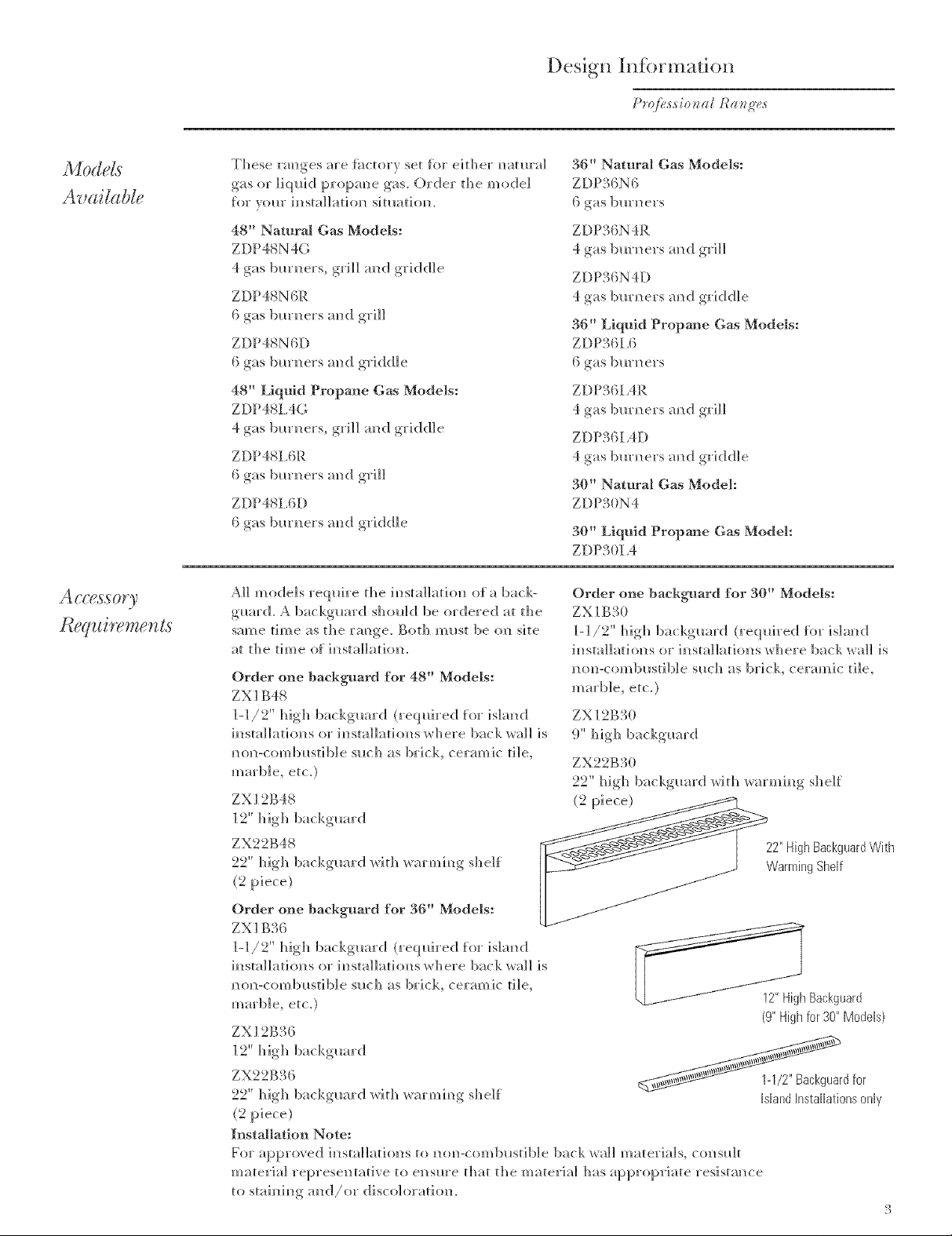
All m ode] s req u]re the in sta]]ati on of a bark-
guard. A bat kguard should be ordered at the
same time as the rm]ge. Both must be oil site
at the time of h]sta]]ation.
Order one baekguard for 48" Models:
ZXI B48
]-1/2" high bat kguard (reql*h'ed for island
im_sta]]at] on s or in sta]]ati on s wh ere back wall is
nun-combustible such as grit]% ceramic 6]e,
marble, etc.)
Order one backguard for 30" Models:
ZX1B; (• '3 )
1-1/2" high backgmwd (required for island
installations or im]sta]]atiuns _here back _%a]] is
non-combustible sltch as brick, ceramic tile,
marble, etc.)
ZX 1_B_ (
9" high backguard
ZX22B30
22" high backguard _qth _%arming shelf
ZX12B48
12" high backguard
ZX22B48
22" high bad<guard xqth x_armim_gshelf
(2 piece}
Order one backguaJ-d for 36" Models:
ZX1B;BC
1-l/2" high backguard (required for island
im]stall ati o]]s or im]stall ati orals _h ere back wall i s
non-combustible such as brick, ceramic die,
maH)Ie, etc.)
Z'_ *9" B{'
A / _D_ }
12"high ba(kguard
ZX22B36
_rd for
22" high backguard Mth _arming shelf
(2 piece)
Installation Note:
For a pp roxed im]stall ati (n ] s to m]oral-corn b i_sti b]e back _a]] m at eH a] s, c(n ] s_d t
material repi'eseutative to e_/sm'e that the material has appropriate resistance
to stai nin , an d/or discoloration.
12" kligh Backguard
(9" kiigh for 30" Models)
Island Installations only
Page 4
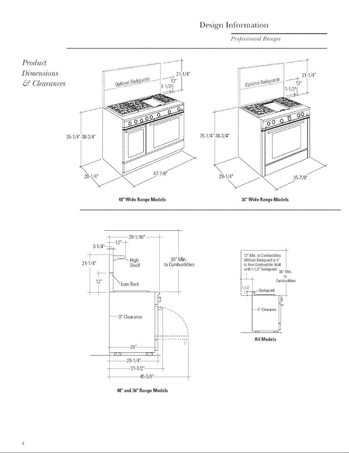
Prod_gct
U C[earm_c_,;s
Desigl, I!,formad<m
tb'@,,ssio_ag [:a*/g'es
35-1/4"-36-3/4"
28-1 _
3-1/4"_12'I
21-1/4" Shelf
48"'Wide Range Medems
29-1/16"
_ High
LowBack
47-7/8_
to Combustibles
36" Min.
35-1/4 36-3/4"
28-1/4" 35-7/8"
36"'Wide Range Modems
12"Min.to Combustibles
Without Backguardor0"
to Non-CombustibleWall
with 1-1/2" Backguard 36" Min.
1@ _Backguard
to
Combustibles
......O"Clearance
-0" Clearance
Aft MedMs
Page 5
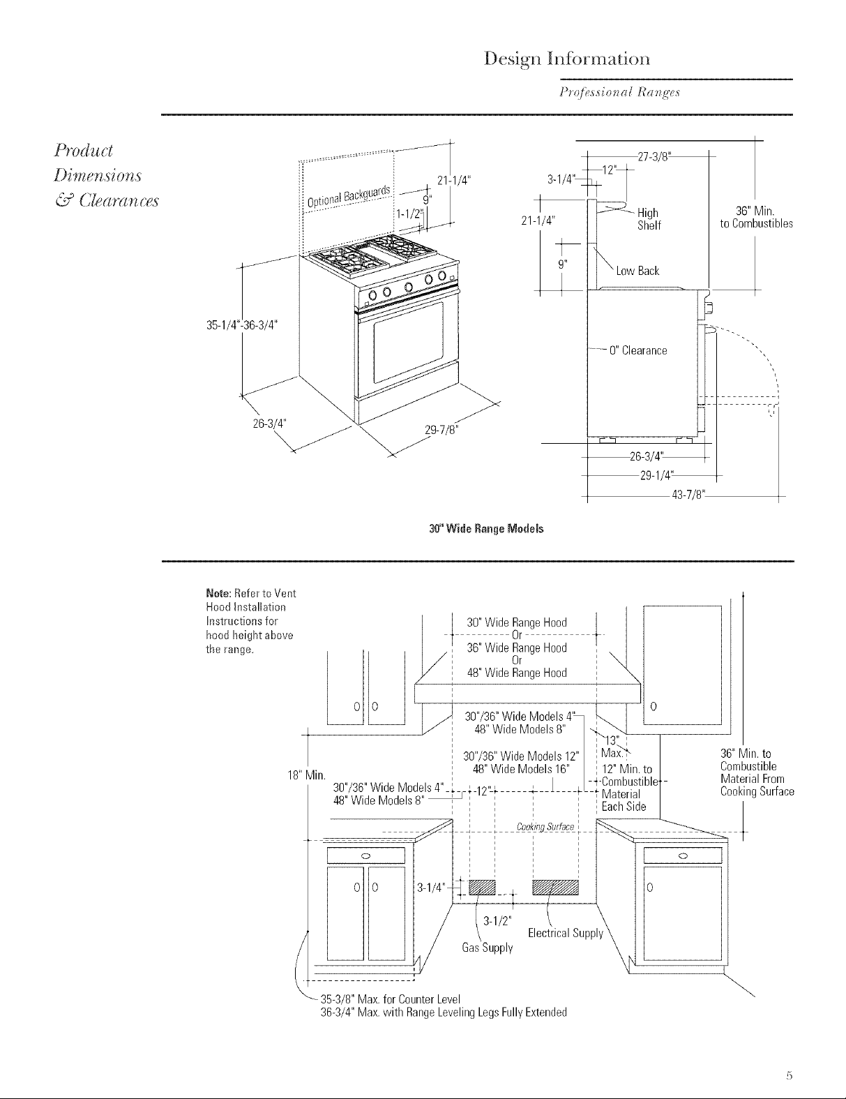
Desigl, Ii,fi rmatio ,
tb'r!i>,s,sio_lag _a _g'e,s
-_27-3/8"
(2earsn,ces
Note: Refer to Vent
Hood Installation
Instructions for
hood height above
the range.
-_ _ High
21-1/4" Shelf
........O"Clearance
30"'Wide Range Models
/ 30"Wide RangeHood ]
I t Or t
I//[ 36`'wideR_ngeH°°d [ _1
/P" 48"Wide RangeHood
I
36" Min.
to Combustibles
_ LowBack
43-7/8"
0"0 ' ] ' ' _-- 0
II I _ 4B,,WideModelsB,, ] .....Q_ _
18"Min. I 48" WideModels16" | 112"Min. to |
30"/36"Wide Model_ • 12,_# - J _ -_ C°_ebUaS[ible[
48"Wide Models8" I i ;'EachSide
o
0 I 3-1/2"
353/8 Max for CounterLevel
36-3/4"Max.with RangeLevelingLegsFullyExtended
, 30"/36"Wide Models4" I
l / I 13" , I
30"/36"Wide Models12" i Max,-'b"
I _ ' L_
ElectricalSupply
GasSupply
36"Min. to
Combustible
MaterialFrom
CookingSurface
/
Page 6

Design hKbrmadon
Advar ,ce
Refer to "Di men si]ms am]d CJearm] ce s" for
appropriate placement and necessary dear-
mices/1hem/ p]mmh]g the im]sta]]atiom
* Cab] m]etrv carol not be h] stall ed direcdv above
the range.
*We recom m era/d the imista]]ati]m of a ve]] t
hood above the sm'lhce.
-The vent hood mllst be at ]east 24" deep.
-The ve]/t hood mllst be the same/lidth as
the range.
-For 48" m ode] s, /t e recom m el/d th e veil t
hood bIo/ler be 1200 (FM.
-For 30" and 36" models, we recommend the
vent hood blower be 600 CFM.
*Working areas ai!jacent to the range sholl]d
have 18" mimlimllm c]earm]ce bettleen
com]tertop mid cabim]et bottom.
* CJearan ce bet11 eel/rm/ge an d side wall or
corn bllstib] e m ateH a] m list be at ]east ] 2" on
each side.
If the range is installed in an island:
*A]hal ]2" mh/. c]earm]ce at the back to
combllstib]e materials.
*A]]oll 36" mira above the cooking sm'fhce to
comb_lstib]e materials.
e For 48" m ode] s,/l e recom m el/d the ve]] t
hood b]o/l er be ] 200 CFM.
* For 30" am]d 36" m ode] s,/l e recom men d the
vent hood be 600 CFM.
* Installation mllst com/Jti_rm ttit]] local codes.
h] the abse_]ce of local codes, the rm]ge
must (omply/lit]i the Natio]]a] Fuel (;-as
('.ode, ANSI Z223A, latest edition.
A.G.A. approved.
7bots &-"
Req .tired:
* Measm'h]g tape
* Carpenter's sqllare
* Pipe and tittim]gs as reqLlired.
* Man ila] gas ]im/e sh m-off valve.
* (;as pressure regulator (supplied)
* i _arge flat-Made sere11 driver
* Pipe/l ten ch
* Drill an d appropriate bi ts
* Satety glasses
* Gas-res] start t pi pe.joi m]t sea]an t
* 5 foot, 5/8" AGA-certified flex]Me metal gas
supply line.
-If reqllh'ed bv local codes, ilse solid pipe
Note: Pro'chase role11flexible lim]e. DO NOT
[ISE OI_D, PREVIOI ISI5 [/SED FI_EXIBI_E
1_INE.
Page 7

Gas Supply:
*T1]e natm'al gas models are designed to
operate at 6" to 14" 1tater cohmm pressllre.
*The ]iqllid propane models are designed to
operate at ] ] to 14" /later cohmm pressure.
A reglllator is required at the LP. sollrce to
provide a maximum of 14"/later pressllre to
the range reglllator.
*These gas ranges are sLqsplied whh ]/2"
NPT fbmale gas com]ection located at the
lef[ rear C(]H/er_
*A 5/S" dia. metal flexible hue is
• For flexible connection, locate p] pe st ub on
t h e back _,lall as ill Llstrat ed.
-- [/se 54oot, 5/8" long flexible gas supply
line.
• For rigid com]ection, locate the pipe stub as
ill Llstrated.
• In] stall a m an ua] sh ut-off valve in t]]e gas
]h/e, h/ an easily accessible location.
Installation Preparation
Pr(b@ssional t¢ang'_,s
4" For 30"/36" Models
8" For 48" Models
12"
._..Gas Supply to Range
Wall ForGas
Supply
Flex Line
Electric Supply:
These ranges must be stlpphed/qtb 208/240
volt, 60 Hz., and com/ected to an individual,
properly groin/ded bran ch circuit protected
bv a circuit breaker or time delta' fllse (50
amp tbr 48" ranges, 30 amp tiw 36" ranges
and 25 amps Jtbr 30" ranges). The receptacle
must be a NEMA 14-50R devise to accept the
4-15ton g p]ug slqsp]] ed wit h the ran ge.
The range is eq ui pped for use with an
electrical slqsp]y tt hich Ilses a separate
groin]cling condllctor (4/1ire s}stem).
If this range mllst be comlected to an
e] ec tr] ca] svst em/l h]c h Ilti] ize s a s]n g]e
conductor for grom/d and nemral (3 wire
s}stem), the grom]ding,im/gser at the
terminal block mllst be connected. The
groin] di ng,i m//per is ]ocated beh]nd the
fl'on t kick pan eL
If the electrical service provided does not
meet the above specifications, it is recom-
mended that a licensed electrician install an
* [ x)cate the e] ectri c slqsp]y as i]] ustrated.
Green
/Black
TerminalBlock
To connect grounding jumper:
*Discon n ect restrai n ing dip h o]di n g j um per.
* (onnect green jm]/per to open term ina] on
ne utra] ( tl h]te) p or ti o]] of the term ina]
b]ock.
Page 8

Installation
Before moving the range indoors:
*Remove ulster carton and pa(k]ng material
from the shipping base.
LeftRearShipping
Screws
DoorHingeRoller
(Closed)
Un-Lock
Remove oven doors:
* Opel] t]_e door fu]]v an d h o]d d<_ ]].
* (lose die brass hinge latches to locked
positi<m on each side.
* C_aref u]]y, ]]ft am]d p i_]] t]_e dour m_ av fi'um t]_e
1"am/ge am] d o Ht uf t]/e _}'am e.
RangeMust
beUniformly
Supported
onBraces
The range is secm'ed to the skid _]th 2 bolts in
the fI'om]t am] 2 "]/' brackets <m the bottom
flmlge of the range back. Remove bu]ts and
"I/' brackets.
To simplify handling and to reduce the weight
of the range:
* Remove d_e grates and drm_ ers be]o_ d_e
knobs.
*Remuve grill mid griddle covers. DO NOT
ATTEMPT TO REMOVE A GRII _i_OR
GRIDDI _E ASSEM B1 _St
* Rein ove the broil er pan s/]i terat m'e pa_ kage
from h_side ovem_(s).
LevelingLeg:
Due to the _eight of these rm]ges, use a do]Iv
_ it]] soft _ h eel s to m uve t his rm_ ge.
* 1_fftt]]e ran ge on to the do]Iv all d m uve
in doors.
Page 9

H stallati(m
P*'@,ssio_vag t_a:_g'es
Step
36" and 48" Wide Models:
* Rein ove t]]e pail e] fl'om the rear of the
shippim/g pack. I.ay tile pa_]eI ore/tile floor
di rec t]v i]] t}'ol] t of th e ira/stall ati oil ]o cati oil.
Tile ram]ge shol_]d be p]aced on this pane] to
prevem]t damage to the floor.
All Models:
* Rein ove t h e ttl O str] pe t_x]m the ove]]
im]terior. Place the stripe oil the floor at the
]e_ am]d r]ght sides of t]]e ira/sta]]at] oil
]ocatJtm. These str]p s provi de a sIl]'%ce for
s]JdJm/g the range im/to the lira/a] posJtio]/ and
%1]] I.)I'evei]t damage to the {loot. The
]eve]im/g legs midst rest permamlei]t]y oil these
I'tlm]]] el" st]'] pc.
Note: Rear rm/ge ]evelim/g legs are n(]t acces-
sib] e at}er ira/sta]]ati oil.
* C_heck to be slate the a({ioim]]m]g cab]inlets/
col_m] tert op s are ]eveH I_'o_] t to ba(k am] d ]eft
to right across the opeiiiFlg of the rm]ge.
*Measl_re the distamlce [}'ore the floor to the
topofthecomltertopim] the]eflamldr]ght
]'e_]]" COH] e]'s.
,,_-'_---1 Range
| Opening |
[ II /// ToSupport
evehngLe
* A(]il_st the h eight of th e ramlge to corn] ter top
h eigh t or high er.
IMPORTANT: The rm]ge shol_]d a]/tays be
i_]sta]]ed at co_mtertop ]]eight or higher. DO
N OT IN STAI _i_THE RANGE I,OWER THAN
ADIACENT (O[/NTERTOP HE[(;HT.
_.AimRa,ges Ca, ]]p
i,jar_ Co,id Res,it
° m.stammA i-Tip
B_acRe_P_ovided
* See i.s_r.etio.s
The m]ti-tip bracket is deeiglied to be i_]sta]]ed
(]_/ top of the slide (framers)provided/lit]]
the rm/ge. Any other type of co]]str_ct]o_] may
req_ire special i_/sta]]atiol] tec]miq_es to
i_]sm'e ad eq _ate J_ste]]]_] g oJ_the a_]ti-ti p
bracket to the {]oor or flail.
*The bracket m_st be proper]v i_]sta]]ed to
pl'evei/t tippi_]g of the rm]ge.
*Read the AHAM A_]ti-Tip Satetv brochette
packed _r]t]_ t]_e prod_lct.
A]] Ra_]ges m_st I/ave an] m/ti-tip device
correctly i_]sta]]ed at cordi_]g to these
] _]st]'_lct] o_1S.
* If the rmlge is p_l]]ed o_*t J_'om the /la]] ii_r
a_]y reaso_], make s_re that the de_ice is
properly ei/gaged/the]] plashed back agai_/st
tile /la]] or i_/sta]]atio_] posJtio]].
* If the ai]ti-tip device is _]ot eilgaged, there is
a possible risk that the ra_lge ca_] tip over
a_/d cayuse ]_i_rY if yo_ or a ch]] d start d, s]t or
lean on m/ (]pe_/ door.
[41#10x2"woodscrews
Anti-Tip Bracket
AHAM Anti-Tip
SafetyBrochure
Page 10

SmallHolesForWood
Installations
Wood
Slide
Strip
Installatkm
tb'qik,s,sio,(d l,_a,g'e,s
SmallHoleForWood (2)WoodScrewsinto
Installations(2Total) BackWall
(2)LargeHolesFor \ (All Installations)
ConcreteInstallations
Back
Wall
Wood Construction:
* P]a(e th e b_'acket agai n st t h e back wail hi to the
righ t rea_" coH_ e_" of t]]e hi sta]]ati (m ] (>cad o_.
e See Dim eli si o]] A_ p usi ti om] the b_'acket the
coH'ect distance fl'om the Hght side. Mm'k the 2
small sc_'ew holes {_n" f;_stem_h_4 the b_'acket to
the {]uo_" and _'emove the b_'ackeL
eDH]] tv, o_ l/S" diameter" pilut holes,
e Fastem] the b_'acket sec m'e]v to the fl oo_" an d _ a]]
i_s]ng a]] 4 sc_'e_ s p_'ovided.
Concrete or Cement Construction:
Ha_'d_m'e Reqlfi_'ed (m)t sl_pp]ied) :
[2] sleeve am]ch(ws_ lag bolts am](] washe_'s.
• Place the bi'acket a_4ah]st die back _a]], into the
]'igh t ]'em" coH] e_"of t h e hi stall ati on ]ocati(m.
• See D] mem/ s]om] A_ positiui/ tile b_'acket the
cuH'ect dista_]ce fl'om the H gh t side. Mm'k the 2
]ai'ge holes for f;_stei]hig the b_'acket to the floor
am]d I'em ove the b_'ackeL
• D]']]] _'ecommeiided size holes %I" the haTdv, a_'e.
hi stall the s]eeve m]ch u_'s hi to the ho]es an d th eli
install the lag bolts t]]_'ough the b_'ackeL The
bo]ts must be p_'opeHy tigh te_] ed as _'ecum-
mei]ded fk)_" the ]_m'd',_ ai'e.
Faste_] the bTacket secm'e]v to the fi ooT.
DHve _ ood sc_'e_ s hi to the bark _ a]].
! 0
Page 11

Installation
Prqi_<ssio_la{ ]_a_zg'es
Connect
to Gas
A m am_I_a] sh la-off _a]_e m I_st be im_stall ed _1_ere
it _i]] be a_ cessib]e+
Assure that gas is turned off at the shut=off
valve,
* Remove a]] bllrn er/hanger scre_ s+
+ [ _ift an d rein ove a]] opem] top bl_rm]ers/h m]gers
to reveal the gas inlet location at the back of
+Pull the flexible metal gas line through the
back of the range an d in to the cooki n g area
m]til it meets the regular.
+ (:om]ect flexible metal connector to incoming
gas hne pipe stub.
+Tm'n on gas an d ch eck lot leaks:
-[Ise a liquid leak detector at all,joints and
con n ecti orals in t h e sxstem.
Flexor RigidGas
LineToRegub
Regulator
36"Models
Flexor RigidGas
LineToRegula
Regulator
30" Wide Models:
Rigid pipe is t;_ctory hi stall ed fl'om the
regl_]ator to the bottom rear of the range.
Flexible line may be used to connect to the
pipe stub+
A bad<guard is required fl>r a]] installations+
+ hi sert the backguard into the guide
cham_e]s on the back of the range+
+Secm+e the backguard to the range at the
rear _ ith th e 4 sh eetm eta] sere_ s pr ovi ded+
+h]sta]] 2 or 3 sc1+e_s thrtmgh the t}+om]tof
the rm_ge, dependh_g om__r_>_+ mode].
48"Models
FactoryInstalled
RigidGasLine
\
Regulator
30"Models
] ]
Page 12

Connect
Ix]stallafiox]
PIing power cord into properly grom/ded
* C_arefl_]]y, s]] de tbe rm]ge in to positi on.
-Be careh*] m]ot to em/tm]ge po/_ er cord m] d
gas flexible robing.
* Be slate the rig]It rear leg is engaged ira] the
s]o t of t b eim] stall ed all ti-ti p bracket,
* CJ_eck for proper bista]]at]om] by grasph]g the
range at the top front edge mid carefl_]]v
at tern p t t o ti]t tbe rm] ge Itbr t_ ard.
*(beck to be sm'e the from of the range is
level A({jl*st {i'(mt ]eve]im]g legs accordi_g]y:
* Replace tbe f}'on t kick pro]el by reversi ng tbe
procee(b_re described ira] Step ]1.
8t_ 8
R@lace
Ove, ,Door(,9
To replace the ()veil doors:
* Sh de t]] e b h] ge s h] to tb e op en h] gs. Th e
bhige s]loll]d rest ic_ the center of eatb
bil]ge roller.
* ()pe(] th e door fl_]]v an d m/] ock bin ge
latches.
( A[ ITION: Take care/_be]i rep]ach/g the
oven doors. If the bimlge latch is mlot secm'e]v
locked, the him/_ge may sm_p back mid sepa-
rate. If th e bim]ge separates, you m i_st apply
pressllre (possibly with yore" toot) to press it
back together and then engage the brass
hh_ge latch.
DoorHingeRoller
(Closed)
Un-Lock
]2
Page 13

kssemb[e
c A "
*Rep]a< e the bm'm]er bowels and bm'm]er caps.
*A<{justm en ts sh old d m_ot be req uired, m_l ess
vibration durim_g transit or variations im_local
gas supply make m in or a({j ustm en ts n e ces-
SaI'%
CA[JTION: Bm'm]er a<!jllstments mllst be made
by a q ilalifi e d t ech n ]c]an at th e ti m e of h] st all a-
don. Extreme care sholl]d be ilsed if a/]illst-
m e_]ts are m ade at_er h] sta]]at] on.
* Bm'mler flare es sh o u]d be b] lie am1d stab] e wi th
no ve]]o_l or ve]]o_l tips, excessive m]oise or
li}}in g of the flare e from the bm'n en If am]v of
these conditions exist, check that the air
shlltter or bm'ner ports are m]ot blocked. If
on e of these co_] diti o_]s con tin lies, a({j ust the
ah" shlltter as reqllh'ed.
-If t h e flam e is too yell o_l, th ere is in sllt}i cien t
ah" flow, adjllst the shmter com]terclock_ise
to h]crease ah" inlet.
-If the flame is nois', oi" tem]ds to ]]t_ m_av
_?'om the b m'n el, t here is too milch air+ Tm'n
the shlltter clockwise to re(blce air.
Installation
Pr:_:l>ssio_vag t_a:_g'es
_lgniter
lurner-
-Main Burner
Venturi(rear)
(e i
gniter- _ _ _- SimmerBurner
lurner- _ 'i)-venturi(rear)_ -AirShutter
MainBurner SimmerBurner
Venturi(front) Venturi(front)
Step
The open top bm'm]ers mid grill w_]ves l/ave an
adjllstab] e low setti ng. Each va4ve is in divi du-
ally tested m] d a({j listed before it ]s sh]p ped.
M]n oi" a/]j ustm en ts mav be requ]red (ble to
fl _lct_lati on s i_] ]oca] gas pressm'e. A (!j_lstm ell ts
to i_1crease oi" decrease gas tl o_l m av be
necessarv.
*Tm'n ]mob com]ter-cIockxlise to tile IJTE
* ()_]ce ]it, tm'n the knoll back to the "[.()W"
* Rein ove the k]] oh.
* In sert a thin-blade flat screwdriver in to the
valve sh all ( 3/ 3 2" b] ad e w] th recom -
* Grip die shaft _lit]/ pliers and mrn tile
Place the bm'ner grates h]to operating position.
Press corner of the grate to the cooktop. The
grates sh o_d d be seated an d sh o_l]d not rock.
Models equipped with grill and griddle:
*Tile grill mid grhkHe are secm'ed with screws at
the Jh'onL They are desig_]ed to be stathmarv
a_] d Sh o11] d _]ott/) be removed.
scre_ driver co m] ter-c] ock_ i set o ]o_l er the
flame, oi" c]ock_ise to increase the {Jame.
(AilTION: Do not mrn the {Jame so ]o_a that
it goes trot, cmlshlg the igniter to spark.
* When the desh'ed setth]g is made, replace
the k]]ob m]d tmq] bmmler off.
*The grhId]e has two leveling screxls beneath
the rear fi _le cover which can be _lsed to
a(]j ust to th e desired s]ope. The ce_] ter screw
is %I" shipping pro'poses o_]]y mid sho_dd be
rein oved.
]3
Page 14

Notcs
14
Page 15

Notes
15
Page 16

Pub.No.49-8814-5
Dwg.No.164D3333P058
(NO 728) 3/03
10658Rev 7
Note: While performing installations described in tills book,
safety glasses or goggles should be worn,
_Gr ,_lono_'_(t.i _ loc(d s(.l'.icc i. yo._ (_(.(_, c(dl
1-600-444- / 84 ).
Monogram;'
Webringgo_Jdthingstolife,
GEDmsunler Produc _u
General Electric [;onlpany
Louisville, KY40225
@2003 (@neralElectro Company
 Loading...