

Page 1

Installation
I struct" n
30", 36" and 48"
Professional Ranges
Cuisini_res professionnelles
de 30" (76 cm), 36" (91 cm)
et de 48" (121 cm)
Instructions d'installation
La section fran_aise commence _ la page 24
Cocinus profesionales
de 30", 36"y 48"
Instrucciones de instalaci6n
La secci6n en espa_ol empieza en la p6gina 46
Page 2
Installation Instructions
BEFORE YOU BEGIN
Read these instructions completelg and corefullg.
•IMPORTANT- savetheseinstructionsfor
local inspector's use.
• IMPORTANT-Observeall governing
codes and ordinances.
• Note to Installer- Be sure to leave these
instructions with the Consumer.
• Note to Consumer - Keep these instructions
with gour Owner's Manual for future reference.
• Completion Time- 1to 3 hours.
• Proper installation is the responsibilitg of the
installer. Product failure due to improper
installation is not covered under the warrantg.
See Owner's Manual for warrantg information.
AWARNING:
This appliance must be properlg grounded.
See "Electric Supplg."
For Monogram local service in gour area,
1.800.444.1845.
For Monogram Service in Canada, call
1.800.561.3344.
For Monogram Parts and Accessories, call
1.800.626.2002.
If gou received a damaged range, gou should
contact gour dealer.
In the Commonwealth of Massachusetts:
• This product must be installed bg a licensed
plumber or gas fitter.
• When using ball tgpe gas shut off valves, theg
shall be T-handle tgpe.
• A flexible gas connector, when used, must not
exceed 3 feet.
- WARNING:
All ranges can tip. Injurg could result. Install the
supplied Anti-Tip Bracket provided. See instructions
in this manual or with the bracket.
Vent hood Combinations:
It is recommended that these ranges be installed
in conjunction with a suitable overhead vent hood.
• Install a hood with at least 1200 CFM above a 48"
wide range.
• Install a hood with at least 600 CFM above a 30"
or 36" range.
Due to the high heat capacitg of this unit, particular
attention should be paid to the hood and ductwork
installation to assure it meets local building codes.
- WARNING:
Clearances to horizontal surfaces above the range,
measured to the cooking surface:
• Installations without a hood require 48" minimum
to combustibles.
A custom hood installation with exposed
horizontal combustibles surfaces must have
an Auto-On feature.
For other installations with a hood, refer to hood
installation instructions for specific hood
clearances.
CAUTION:
These ranges weigh up to 700 pounds. Some
disassemblg will reduce the weight considerablg.
Due to the weight and size of the range and to
reduce the risk of personal injurg or damage to
the product:
TWO PEOPLEARE REQUIRED FORPROPER
INSTALLATION OF 36" AND 30" RANGES.
THREE PEOPLEARE REQUIRED FOR PROPER
INSTALLATION OF 48" RANGES.
Leak testing of the appliance shall be conducted
according to the manufacturer's instructions.
Installation must conform with local codes. In the
absence of local codes, the range must complg with
the National Fuel Gas Code, ANSIZ223.1/NFPA 54,
latest edition and National Electrical Code
ANSI/NFPA 70 latest addition. In Canada, installation
must conform with the current Natural Gas
Installation Code, CAN/CGA-B149.1 or the current
Propane Installation Code, CAN/CGA-B149.2, and
with local codes where applicable. This range has
been design-certified bg CSA International according
to ANSI Z21.1, latest edition and Canadian Gas
Association according to CAN/CGA-I.1 latest edition.
Page 3

Design Information
CONTENTS
Design Information
Models Available ......................................................................:3
Backsplash Accessories ......................................................3
Product Dimensions and Clearances ........................4-7
Tools and Materials Required ..........................................8
Installation Preparation
Power Supply Locations ..............................................9, 10
MODELS AVAILABLE
These Monogram ranges are factory set for either
natural gas or LP gas. Order the model for your
installation situation.
48" Natural Gas Models:
ZDP484NG - 4 gas burners, grill and griddle
ZDP486NR - 6 gas burners and grill
ZDP486ND - 6 gas burners and griddle
48" LP Gas Models:
ZDP484LG - 4 gas burners, grill and griddle
ZDP486LR - 6 gas burners and grill
ZDP486LD - 6 gas burners and griddle
Installation Instructions
Step 1, Remove Packaging ..............................................
Step 2, Hove Range Indoors ..........................................
Step 3, Install Anti-Tip Device ........................................
Step 4, Connect Range to Gas........................................
Step 5, Connect Electrical ................................................
Step 6, Roll Range into Position ....................................
Step 7, Level the Range ....................................................
Step 8, Replace Oven Doors ............................................
Step 9, Check Burners ........................................................
Finalize Installation ..............................................................
Installation Checklist ..........................................................
Accessories ..............................................................................
Accessory Installation ................................................18-20
Gas Conversion ............................................................21-23
36" Natural Gas Models:
ZDP366N - 6 gas burners
ZDP364NR- 4 gas burners and grill
ZDP364ND - 4 gas burners and griddle
36" LP Gas Models:
ZDP366L- 6 gas burners
ZDP364LR - 4 gas burners and grill
ZDP364LD - 4 gas burners and griddle
30" Natural Gas Model: ZDP304N
30" LP Gas ModeI:ZDP304L
1
2
3
.4
4
4
5
5
6
6
6
7
BACKSPLASH ACCESSORIES
All models require 12" minimum clearance to a
vertical combustible surface at the rear. If clearance
is less than 12", the entire surface of the back wall
above and the full width of the range must be
protected by a backsplash. The backsplash must be
constructed of non-combustible material, such as
metal, ceramic tile, brick, marble or other stone.
Two Backsplash AccessoriesAvailable:
• The 12" high stainless steel backsplash accessory
is available. Use this backsplash in combination
with a custom, non-combustible backsplash built
beyond the 12" height. The combined height of
the backsplash accessory and the custom
backsplash must reach the bottom of a hood,
or when there is no hood, to 48" above the
cooking surface.
• An adjustable 30" to 36" high backsplash with
shelf is also available. This backsplash fills in the
space between the top of the range and the
bottom of the hood. The shelf is positioned so that
heat lamps from the bottom of a Monogram
professional hood are directed towards the shelf.
12"HighBacksplash
ZX12B48PSS,for48" wideranges
ZX12B36PSS,for36" wideranges
ZX12B30PSS,for30" wideranges
30"to36" AdjustableHeight
BacksplashWith Shelf
ZXADJB48PSS,for 48"wide ranges
ZXADJB36PSS,for 36"wide ranges
ZXADJB30PSS,for 30"wide ranges
3
Page 4

Design Information
PRODUCT DIMENSIONS AND CLEARANCES
48" Range Models
I "
Countertop
_ .......47-7/8"Width to Cooking
.............. Surface
UniversalUtilityLocations
35-1/4"
to
36-3/4"
Height
28-1/4"
Depth
to Front
of Door
- WARNING:
Installations without a hood require
a8" minimum to combustibles.
Acustom hood installation with
exposed horizontal combustible
surfaces must have an Auto-On
feature. Referto hood installation
instructions for specific hood
clearances.
The surface of the entire back wall
above the range and below the
hood must be covered with a non-
combustible material such as metal,
ceramic tile, brick, marble or other
stone.
1% I1 i
3-1/4"
to 4-3/4"
Toel<icl</leg_'
Height
12"Minimum
', toAd acentWall
Max.
ADDITIONAL CLEARANCES:
Allow 12" minimum clearance to an adjacent wall
on each side.
Working areas adjacent to the rangetop should have
18" minimum clearance between countertop and
the bottom of the wall cabinet.
4
Page 5

Design Information
PRODUCT DIMENSIONS AND CLEARANCES
36" Range Models
1 "
35-7/8"Width
35-1/4"
to
36-3/4"
Height
Countertop
to Cooking
Surface
UniversalUtility Locations
28-1/4"
Depth
toFront
of Door
WARNING:
Installations without a hood require
48" minimum to combustibles.
A custom hood installation with
exposed horizontal combustible
surfaces must have an Auto-On
feature. Refer to hood installation
instructions for specific hood
clearances.
The surface of the entire back wall
above the range and below the
hood must be covered with a non-
combustible material such as metal,
ceramic tile, brick, marble or other
stone.
Toel<icl</leg
Height
12"Minimum
to Ac acentWall
48"Minimum
toCombustibles
Max.
ADDITIONAL CLEARANCES:
Allow 12" minimum clearance to an adjacent wall
on each side.
Working areas adjacent to the rangetop should have
18" minimum clearance between countertop and
the bottom of the wall cabinet.
5
Page 6

Design Information
PRODUCT DIMENSIONS AND CLEARANCES
30" Wide Range Models
29-7/8"Width
35-1/4"
to
36-3/4"
Height
28-1/4"
Depth
to Front
of Door
1 "
Countertop
to Cooking
Surface
Toel<icl</legf
Height
UniversalUtilityLocations
12"Minimum
\\
\\
to Ac acentWall
-&WARNING:
Installations without a hood require
/48"minimum to combustibles.
Acustom hood installation with
exposed horizontal combustible
surfaces must have an Auto-On
feature. Referto hood installation
instructions for specific hood
clearances.
The surface of the entire back wall
above the range and below the
hood must be covered with a non-
combustible material such as metal,
ceramic tile, brick, marble or other
stone.
30" Min.
ADDITIONAL CLEARANCES:
Allow 12" minimum clearance to an adjacent wall
on each side.
Working areas adjacent to the rangetop should have
18" minimum clearance between countertop and
the bottom of the wall cabinet.
Page 7

Design Information
PRODUCT DIMENSIONS AND CLEARANCES
48", 36" and 30" Range Models
28-7/8" ............................................................
10-1/2" _
13/16" _ 4
A
ToFrontEdge
Optional
Backsplash
Accessories
30-36"
35-1/4"
to
36-3/4"
v
,,
A
-='v_
,4 28-1/4"To
.
,4t
bl b1
4 ToFrontofDoor
3-3/16"
ControlPanel
Beveled
Edgeof Control
PanelBullnose
27-1/2"To
BeveledEdge
Maximum
AdjacentCabinet
Depthfor
FlushInstallation
28-1/4"
Depth I_-
4
7" ControlPanel
Height
V
u
u
u
12"Min.to combustiblesor 0" to
a non-combustiblematerialabove
thecookingsurface
0"Clearance
- toabackor
sidewall below
thecooking
surface
4 31-1/16"
ToFrontof Handle
48-1/4"
With OvenDoorOpen
WARNING:
The 12" high stainless steel
backsplash accessorg must be
installed in combination with a
custom non-combustible backsplash.
The finished backsplash must cover
the entire back wall up to the bottom
of a hood, or when there is no hood,
48" to combustibles.
Page 8

Installation Information
WB28K10553 HIGH ALTITUDE KIT
For operation above 3,000 feet, order WB28KlOS53
Conversion Kit. This kit includes orifices for both LP
and Natural gas operation.
WB28K10554 DE-RATE KIT
(For a smell kitchen environment.}
De-rate conversion kit for use with model
ZDP304N (natural gas onlg). This kit includes
orifices to reduce surface burner output
to 40,800 BTU's.
MATERIALS PROVIDED
1/2" Pipe OvenRack
Anti-Tip Elbow Lubricant
Bracket,Brace
andScrews
Runners
(toprotect
flooring)
TOOLS REQUIRED
SaberSaw
MeasuringTape
Carpenter'sSquare
SafetyGlasses
Phillips#2Screwdriver
Drilland
AppropriateBits
AdjustableWrench
1/4" DriverorWrench
Level
HandTruck
MATERIALS REQUIRED {not provided}
Joint PipeFittings Shut-0ffValve
Sealant
5-foot maximum length, 5/8" 0.D. CSA-approvedflexible
metal gas supply
(3-foot maximumlength in Massachusetts only)
NOTE: Purchasenew flexible line; do not use
previously used flexible gas line.
Page 9
POWER SUPPLY LOCATIONS
Installation Preparation
Gas Supplg:
•The natural gas models are designed to operate
at 5" water column pressure. For proper operation,
the pressure of the natural gas supplied to the
regulator must be between 7" and 13" water
column.
•The LP models are designed to operate at 10"
water column pressure. For proper operation,
the pressure of the LPgas supplied to
the regulator must be between 11"
and 13" water column.
• A 1/2" elbow is provided for connection
to the range gas inlet, located at the rear
and near the floor.
• Locate the pipe stub on the back wall or floor
as illustrated in "Dimensions and Clearances."
Use 5-foot maximum length, 5/8" O.D. flexible
gas supplg line (3-foot in Massachusetts).
• Install a manual shut-off valve in the gas line
(not provided), in an easilg accessible location.
Make sure the homeowner knows where
and how to shut off the gas supplg to the range.
Electric Supplg:
These ranges must be supplied with 208/240 volt,
60 Hz., and connected to an individual, properlg
grounded branch circuit protected bU a circuit
breaker or time delag fuse (50 amp for 48" ranges,
50 amp for 56" and 50" ranges). The receptacle
must be a NEIVlA14-50R device to accept the
4-prong plug supplied with the range.
If the electrical service provided does not meet
the above specifications, it is recommended that
a licensed electrician install an approved outlet.
• Locate the electric supplg as illustrated
in "Dimensions and Clearances."
-&WARNING
The range is equipped for use with an electrical
supplg which uses a separate grounding conductor
(4 wire sgstem).
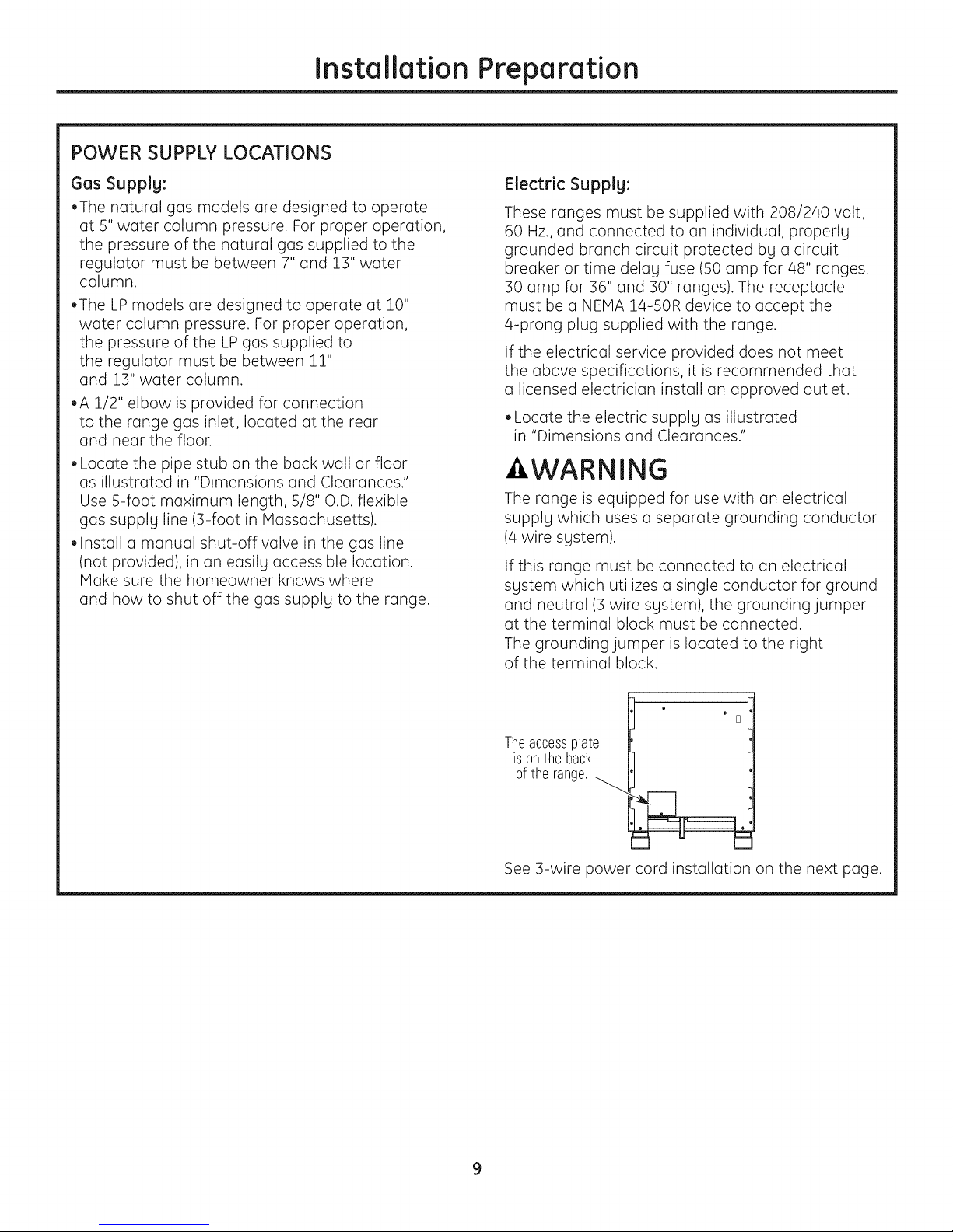
If this range must be connected to an electrical
sgstem which utilizes a single conductor for ground
and neutral (5 wire sgstem), the grounding jumper
at the terminal block must be connected.
The grounding jumper is located to the right
of the terminal block.
o
Theaccessplate
is onthe back
of the range._....
See 5-wire power cord installation on the next page.
o
D
Page 10

Installation Preparation
4-WIRE POWER CORD INSTALLATION
NOTE: A 4-wire cord is connected to the range
at the factory. Use the following steps to change
an existing installation from a 3-wire cord back
to a 4-wire cord.
- WARNING
The neutral wire of the supplg circuit must
be connected to the neutral terminal located
in the lower center of the terminal block.
The power leads must be connected
to the lower left and the lower right
terminals of the terminal block. The 4th
grounding lead must be connected to
the frame of the range with the ground
plate and the ground screw.
• Remove the 3 lower terminal screws from
the terminal block. Remove the ground screw
and ground plate and retain them.
• Remove the ground strap. DO NOT DISCARD
THE GROUND STRAP OR ANY SCREWS.
• Insert the one ground screw into the power cord
ground wire terminal ring, through the ground
plate and into the frame of the range.
• Insert the 3 terminal screws (removed earlier)
through each power cord terminal ring and
into the lower terminals of the terminal block.
Be certain that the center wire (white/neutral)
is connected to the center lower position
of the terminal block. Tighten screws securely
into the terminal block.
GroundStrap
3-WIRE POWER CORD INSTALLATION
NOTE: A 4-wire cord is connected to the range
at the factorg. Use the following steps to change
the range to a 3-wire cord.
WARNING
The neutral or ground wire of the power cord
must be connected to the neutral terminal located
in the center of the terminal block. The power leads
must be connected to the lower left and the lower
right terminals of the terminal block.
• Remove the ground strap (located at the right
side of the terminal block) and connect between
the center lower portion of the terminal block
to the frame of the range.
• Remove the 3 lower terminal screws from
the terminal block. Insert the 3 terminal screws
through each power cord terminal ring and
into the lower terminals of the terminal block.
Be certain that the center wire (white/neutral)
is connected to the center lower position
of the terminal block. Tighten screws securelg
into the terminal block.
DO NOT remove the ground strap connection.
TerminalBlock
aearance
mayvary)
Neutral
Terminal
Terminal or
Block
GroundStrap Neutral
After
Terminal
Block
Ground
Screw
Terminal
Plate
Ground
Strap
NeutralTerminal
GroundPlate
(groundingto
range)
10
Page 11

STEP 1 REMOVE PACKAGING
Installation
CAUTION
Stand clear. The ends of the cut metal banding may
snap toward gou.
•Cut the metal banding. Lift the carton straight up.
• Locate the two runner strips from the top
of the packaging. These strips will be used to
protect the kitchen floor during installation.
• Remove corner posts. Dispose of packaging
materials.
• Remove grill/griddle covers, grill grate and burner
grates.
• Lift out cast-iron griddle flue cover, grease troughs
and pads.
•Cut the ties holding the grill grate to the grill frame.
GriddleFlueCover
• Open oven door(s) and remove packaging.
Remove shelf holding broiler pan, tape, literature
package, shelf lubricant and probe.
\
- CAUTION
Doors and passagewags leading to the installation
location require at least 32" opening. Ifthe opening
islessthan 32",the oven door(s)and controlknobs
must be removed.
REMOVE THE OVEN DOOR(S) ONLY IFNECESSARY to
move the range throughthe doorwags. To prevent
damage tothe sidesofthe range,itwillbe
necessargto pad the cornersbeneath the straps
on the hand-truck.
;10t
G
Ties
• Lift off burner caps and remove foam pad,
then lift off burner heads and remove foam pad.
RemoveFoamPads
GreaseTroughs
Hinge
Lock
To remove the oven door(s):
• Fullg open the door.
• Each hinge has a hinge latch. Close the hinge
latch down against the door frame.
• Firmlg grasp the door at the top sides.
• Close the door to the near-vertical position.
• Lift the door up and pull straight out.
• Remove the control knobs bg pulling them
straight out.
11
Page 12

Installation Preparation
STEP2 MOVE THE RANGE INDOORS
1 Tilt the range forward on the skid.
Toekick
2 Lift the toekick out of the foam base.
, ,,J
3 Drive the blade of the hand-truck beneath
the foam block.
4 Attach the hand-truck straps around the unit.
IMPORTANT: Place the hand-truck straps below
the oven door handles. To avoid damaging the
side panels, place a pad between the hand-truck
and the range.
5 Tilt the range to lower the hand-truck wheels
off the skid.
Hand-Truck
StrapsBelow
OvenDoor
Handles
6 Place the appliance runners on the floor
at the left and right sides in front of the opening.
IMPORTANT" The runners provide a surface for
rolling the range into the final position and will
protect the floor finish. The runners must be
removed before leveling the range.
7 Move the range indoors. Position the range
in front of the installation location, onto
the runners.
You mayneed to remove the front
ofthe foamblockto fit through
the doorway.
IMPORTANT" Do not remove the base foam
block while the hand-truck is in use. Place
the hand-truck blade underneath the base
foam block and transport the range to the final
location.
Range
Opening
Runners
forRolling
the Range
Position
InsertBladeUnder
the FoamBlock
12
Page 13
STEP 3 INSTALL ANTI-TIP DEVICE
Installation
• All ranges can tip.
• BURNSor other SERIOUSINJURIES
can result.
INSTALLand CHECKthe ANTI-TIP
bracket following these instructions.
To reduce the risk of tipping the range, the range must
be secured bg a properlg installed anti-tip bracket. See
installation instructions shipped with the bracket
for complete details before attempting to install.
To check if the bracket is installed and engaged properly,
look underneath the range. The anti-tip bracket should be
inserted into the opening on the anti-tip brace on the
range. If the bracket arm misses the brace to the left or
right, or the bracket arm is not protruding through the
brace opening, the bracket must be reinstalled.
If the range is pulled from the wall for ang reason, alwags
repeat this procedure to verify the range is properly
secured bg the anti-tip bracket.
If gour range has no anti-tip bracket, call 1.800.626.8774
to receive one at no cost.
Ifthe anti-tip device supplied with the range does not fit this
application, use the universal Anti-Tip Device WB2X7909.
Read the AHAP1Anti-Tip Safety Brochure packed with
the bracket.
Anti-Tip Parts Provided
4 WoodScrews
Anti-TipBracket
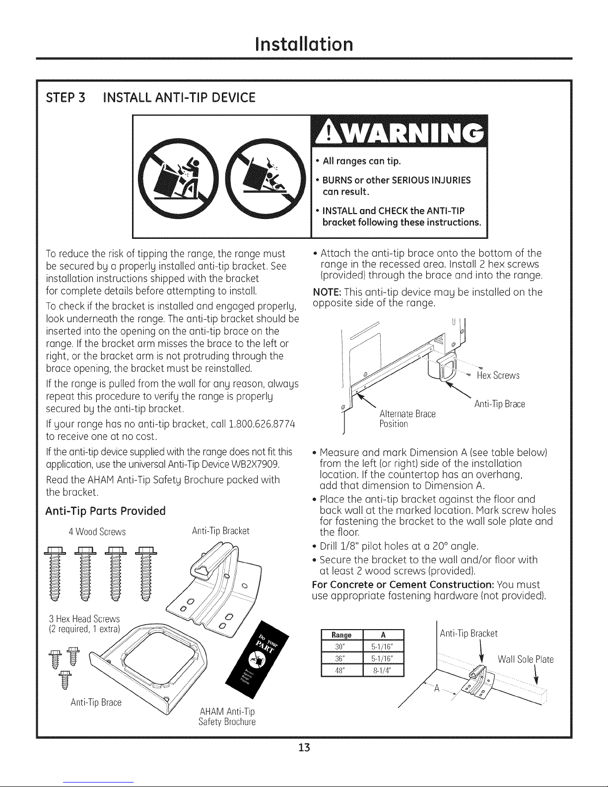
• Attach the anti-tip brace onto the bottom of the
range in the recessed area. Install 2 hex screws
(provided) through the brace and into the range.
NOTE: This anti-tip device mag be installed on the
opposite side of the range.
HexScrews
Anti-TipBrace
AlternateBrace
Position
• Measure and mark Dimension A (see table below)
from the left (or right) side of the installation
location. If the countertop has an overhang,
add that dimension to Dimension A.
• Place the anti-tip bracket against the floor and
back wall at the marked location. Mark screw holes
for fastening the bracket to the wall sole plate and
the floor.
• Drill 1/8" pilot holes at a 20 ° angle.
• Secure the bracket to the wall and/or floor with
at least 2 wood screws (provided).
For Concrete or Cement Construction: You must
use appropriate fastening hardware (not provided).
3 HexHeadScrews
(2 required,1extra)
Anti-TipBrace
AHAMAnti-Tip
SafetyBrochure
13
Range A Anti-TipBracket
30" 5-1/16" !
36" 5-1/16" Wall SolePlate
48" 8-1/4"
/
Page 14

Installation
STEP 4 CONNECT RANGE TO GAS
WARNING
Do not use a flame to check for gas leaks.
Assure that gas supplg is turned off
at the shut-off valve:
• Applg pipe thread sealant to the gas inlet located
at the back of the range. Install the l/2" pipe
elbow (provided) to the gas inlet.
• Connect 5/8" O.D. flexible metal connector
to gas inlet. Connect the other end of the flexible
connector to the house gas supplLI.
Turn on the gas and check for leaks:
- Use a liquid leak detector at all joints
and connections in the sLIstem.
STEP 6 ROLL RANGE INTO POSITION
AWARNING
The Anti-Tip Bracket must be properlLI installed
to prevent tipping of the range. Failure to do so
can cause serious damage or injurLI.
• Check to be sure the appliance runners are
beneath the wheels.
• The range is shipped with the wheels in the down
position. CarefullLI roll the range into position,
being careful not to entangle or pinch the power
cord and flexible gas tubing.
• Remove the runners beneath the range.
IMPORTANT: Disconnect the range and the
individual shut-off valve from the gas supplg piping
system during anLI pressure testing of that system
at test pressures greater than 1/2 psig. Isolate the
range from the gas supply piping system bLIclosing
the individual manual shut-off valve to the range
during any pressure testing of the gas supply piping
sLIstem at test pressures equal to or less than
1/2 psig.
NOTE: This range is equipped with a gas shut-off
valve located on top of the range, beneath the rear
vent. This shut-off valve is to be used in the event
that service is required in the future.
STEP 5 CONNECT ELECTRICAL
• Plug power cord into properlg grounded
receptacle.
• Verifg that power is connected bg opening
the oven door or press the button on the left side
of the control panel to illuminate the accent
lighting.
BesureAnti-Tip
Bracketisengaged
with thebrace
onthe range.
14
Page 15

Installation
STEP 7 LEVEL THE RANGE
AWARNING
The range must be level and be supported
by the legs-not the wheels. The range could move
if the wheels make contact with the floor. Be sure all
legs make contact with the floor in any installation.
• All legs must be leveled after the product is
installed.
• Check to be sure the adjoining cabinets/
countertops are level, front to back and left
to right across the opening of the range.
• Measure the distance from the floor to the top
of the countertop in the left and right rear corners.
• Adjust the height of the range to countertop height
or higher.
IMPORTANT: Thisrange should always be installed
atcountertopheightorhigher.DO NOT INSTALL
THE RANGE LOWER THAN ADJACENT COUNTERTOP
HEIGHT.The range must be supported by all4 legs,
regardlessofcountertopheight.
FRONT LEG ADJUSTMENT
• Slide front cylinders up to adjust front leveling
legs. Be careful not to damage cylinder.
• A leveling leg wrench is supplied. Reach under
the front of the range near the right side. Locate
and remove a thumb screw, then slide wrench out
of the slot.
ThumbScrew
STEP 7 LEVELTHE RANGE (cont.}
REAR LEG ADJUSTMENT
• Remove two screws from rear vent trim. Slide vent
trim forward, then lift up to remove.
• Find the two rear leg extension rods. Use a 1/4"
driver or wrench to adjust the left or right rear legs.
RearVent_im
RearLeg
ExtensionRod
• Replace the rear vent trim using the original screws.
STEP 8 REPLACE OVEN DOOR(S}
Skip this step if oven doors are in place.
IMPORTANT: Do not lift the door by the handle.
To replace the oven doors:
• Firmly grasp the door at the top sides.
This is critical.
• Approach the range with the door angled
in a vertical position.
• Guide the hinges into the slots.
• Push the door in firmly while opening.
• Once in position, open the door completely.
Push the hinge locks back in and toward
the front frame.
• Use the supplied wrench to turn the front leveling
legs. Turn clockwise to raise the range above the
wheels. Turn counterclockwise to lower the legs.
• Be sure to return the wrench to its storage slot
for future use.
Slideleg
cylinderup.
CAUTION: Take care when replacing
the oven doors.Ifthe hingelatchisnot securely
locked,the hinge may snap back and separate.
Ifthe hingeseparates,you must apply pressure
(possiblywithyour foot)topress itback together
and then engage the hingelatch.
15
Page 16
Installation
STEP9 CHECK BURNERS
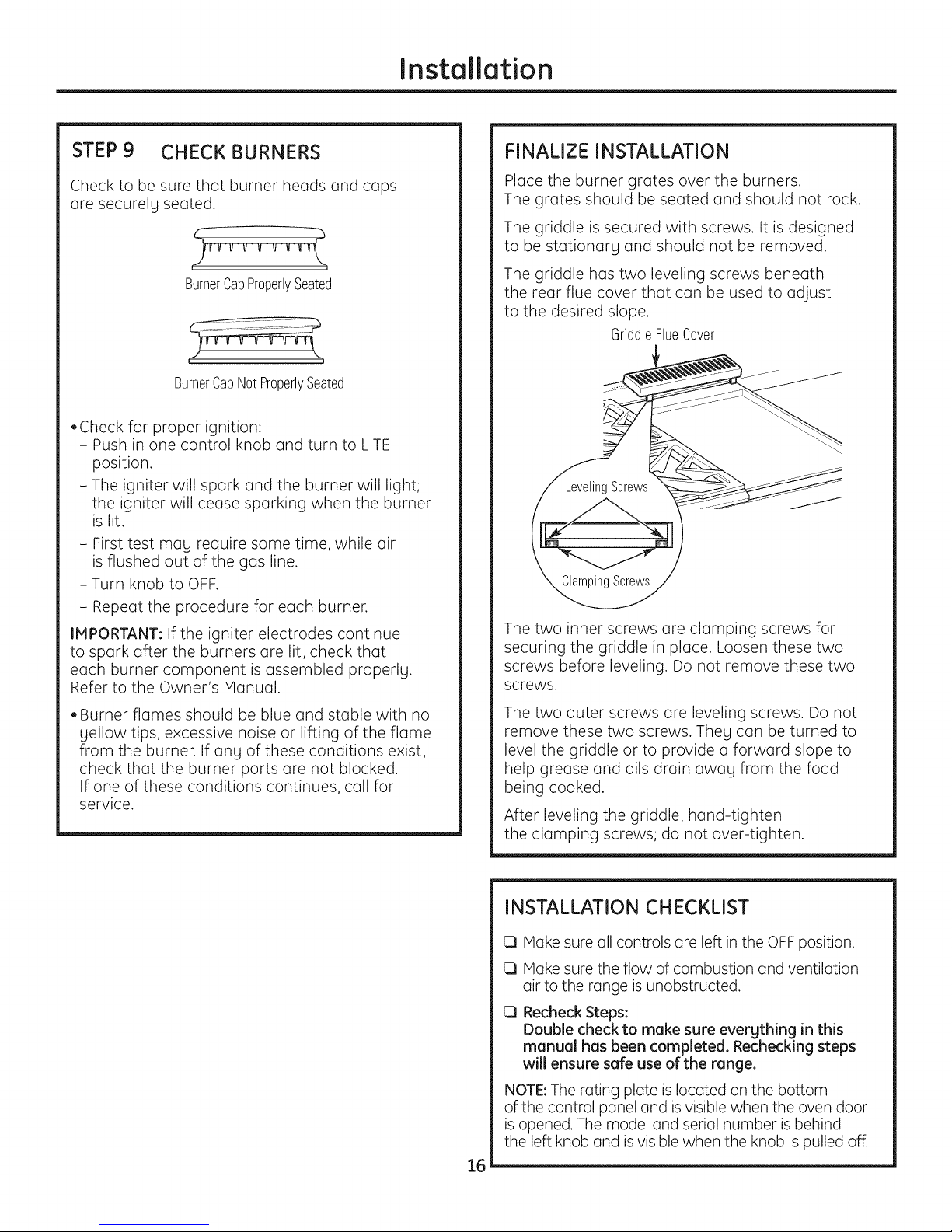
Check to be sure that burner heads and caps
are securelg seated.
BurnerCapProperlySeated
i
BurnerCapNotProperlySeated
• Check for proper ignition:
- Push in one control knob and turn to LITE
position.
- The igniter will spark and the burner will light;
the igniter will cease sparking when the burner
is lit.
- First test mag require some time, while air
is flushed out of the gas line.
- Turn knob to OFF.
- Repeat the procedure for each burner.
IMPORTANT: Ifthe igniter electrodes continue
to spark after the burners are lit, check that
each burner component is assembled properlg.
Refer to the Owner's IVlanual.
FINALIZE INSTALLATION
Place the burner grates over the burners.
The grates should be seated and should not rock.
The griddle is secured with screws. It is designed
to be stationarg and should not be removed.
The griddle has two leveling screws beneath
the rear flue cover that can be used to adjust
to the desired slope.
GriddleFlueCover
_Screws
The two inner screws ore clumping screws for
securing the griddle in place. Loosen these two
screws before leveling. Do not remove these two
screws.
• Burner flames should be blue and stable with no
gellow tips, excessive noise or lifting of the flame
from the burner. If ang of these conditions exist,
check that the burner ports are not blocked.
If one of these conditions continues, call for
service.
The two outer screws are leveling screws. Do not
remove these two screws. They can be turned to
level the griddle or to provide a forward slope to
help grease and oils drain awag from the food
being cooked.
After leveling the griddle, hand-tighten
the clamping screws; do not over-tighten.
INSTALLATION CHECKLIST
Make sure all controls are left in the OFFposition.
Make sure the flow of combustion and ventilation
air to the range is unobstructed.
Recheck Steps:
Double check to make sure evergthing in this
manual has been completed. Rechecking steps
will ensure safe use of the range.
NOTE: The rating plate is located on the bottom
of the control panel and isvisible when the oven door
is opened. The model and serial number is behind
the left knob and isvisible when the knob is pulled off.
16
Page 17

ACCESSORIES--TOEKICK (provided)
Installation
• Install the toekick after the range has been leveled.
• Measure the distance between the floor
and the bottom of range.
• Loosen the two screws on each end. Adjust
the toekick height bg sliding the upper and lower
pieces apart to 1/8" less than the measured height.
oSecure the top and bottom sections bg tightening
the 2 screws on each end.
oPush toekick against range leg until clip snaps
to legs.
NOTE: Be sure the toekick snaps securelg to the leg.
Topof
Toekick
Bottom
ofToekick
Screw
Push
Push
17
Page 18

Z×12B30PSS,Z×12B36PSS,Z×12B48PSS AccessorgInstallation
OPTIONAL ACCESSORIES--12" HIGH BACKSPLASH
WARNING:
To prevent ignition of combustible materials,
the entire back wall above the range must
be protected bg a backsplash constructed
of non-combustible material.
This stainless steel backsplash accessorg
must be installed in combination with a custom,
non-combustible backsplash built begond
the 12" height of the backsplash.
BEFORE YOU BEGIN
Reed these instructions completelg
end cerefullg.
IMPORTANT: Sere these instructions for Iocel
inspector's use.
IMPORTANT: OBSERVE ALL GOVERNING CODES
AND ORDINANCES.
NOTE TO INSTALLER: Be sure to leeve these
instructions with the Consumer.
NOTE TO CONSUMER: Keep these instructions
with gour Owner's Menuel for future reference.
INSTALL 12" BACKSPLASH
-AWARNING: Thisbeckspleshmust
be securely fastened to the well. Failure to do
so could result in damage or personal injurg.
• Install and level the range or rangetop and the
range hood according to the installation
instructions.
• Remove the backsplash packaging and
protective film.
• Usea level to pencil o horizontal line on the wall,
1/8" above the range or rongetop. The 1/8" gap
allows the cover panel to overlap the wall support
panel.
• Locate wall studs on each side. Where studs ore not
available, plan to use wall anchors (not provided).
• Align the wall support panel on the marked
horizontal line and centered left to right.
• The wall support panel must be secured to the wall
at oil 4 corners. Use wood screws (provided) or wall
anchors (not provided) to secure the support panel
to the wall.
• Place the cover panel over the wall support
panel and secure with Torx screws (provided).
Install 2 screws on each side.
This kit provides for the instelletion of e 12" high
becksplesh for 30", 36" or 48" Monogrem
Professional Ranges end Rongetops.
TOOLS AND MATERIALS REQUIRED
• Gloves to protect against sharp edges
• T-15 and #2 Phillips screwdrivers Wall Support
Drill with :3/32" and 9/64" bits Panel
• Pencil
• SafetgLevelglasses
This Kit Includes
• Wall support panel
• Cover panel
• Hardware package with
- 5 Stainless Steel Torx 15 #8
self-tapping screws
- 5 Phillips #2 pan head wood
#10 screws
Hardware
Package
Wall
Support
Panel
Install4 Wood
Screws
Wall Support
Panel
.... _ InstallT-15
o_ Screws
CoverPanel
18
Page 19

ZXADJB30PSS,ZXADJB36PSS,ZXADJB48PSSAccessorg Installation
ACCESSORIES--30" TO 36" ADJUSTABLE BACKSPLASH (not included}
AWARNING:
To prevent ignition of combustible materials,
the entire back wall above the range must
be protected bg a backsplash constructed
of non-combustible material.
BEFORE YOU BEGIN
Read these instructions completely
and carefullg.
IMPORTANT: Save these instructions for local
inspector's use.
IMPORTANT: OBSERVEALL GOVERNING CODES
AND ORDINANCES.
NOTETO INSTALLER:Be sure to leave these
instructions with the Consumer.
NOTETO CONSUMER: Keep these instructions
with your Owner's Manual for future reference.
• This backsplash adjusts to fit the space between
the top of the range and the bottom of the hood,
from 30" Min. to 36" Max. height.
• Maximum shelf load-bearing weight is 40 Ibs.
INSTALL THE WALL SUPPORT PANELS
WARNING:Thewallsupportpanels
must be securel 9 fastened to the wall. Failure to
do so could result in damage or personal injurg.
IMPORTANT:Thisbacksplash isdesigned to cover the wall
between the bottom of the hood and the top of the range.
The vent hood should be installedover the rangetop or
range before installing this backsplash.
• Install and levelthe Range/Rangetop according
to the product installation instructions.
• Removebacksplash packaging and protective film.
Locatewall studson each side.Where studsare not
available, plan to usewall anchors (notprovided).
Usea levelto pencil2 horizontal lines on the wall,
one 1/8" below the vent hood and the other 1/8" above
the Range/Rangetop.This1/8" space allows the cover
panels to overlap the wall supports.
Securethe top wall support panel to the wall with 4wood
screws,through the outermost studs.
Use4 wood screwsto securethe bottom wall support
panel.The center slotshould be positioned at the top.
The gap between the top and bottom support panels
will be covered bUthe top cover with shelf.
Securethe top
paneltothe wall
with 4wood
screws
TOOLS AND MATERIALS REQUIRED
• Gloves to protect against sharp edges
• T-15 and #2 Phillips screwdrivers
• Drill with 3/32" and 9/64" bits
• Safetg glasses
• Level TopCover
• Pencil with Shelf
• Top wall support
• Bottom wall support
This Kit Includes
• Top cover with shelf
• Bottom cover
• Hardware package with
- 9 Stainless Steel Torx 15 #8
self-tapping screws
- 9 Phillips #2 pan head wood #10 screws
- 3 Stainless Steel #2 truss head
#10 screws (for alternate
installation method)
BottomWall Support
TopWall
Support
Hardware
Package
19
Wood
Screws
Secure
the bottompanel
to the wall with
4 woodscrews
Page 20

ZXADJB30PSS,ZXADJB36PSS,ZXADJB48PSSAccessorg Installation
INSTALL COVER PANELS
See alternate method if side access is blocked.
• Hold the bottom cover over the bottom support
while driving one screw (provided)into each side.
• Place the top cover with shelf over the top wall
support. If you have access to the sides, secure
the panel with two screws on each side.
Secure the top cover with shelf to the top
support with screws through the front of the panel,
at the top corners. Use one screw on each side.
Install
Screw
Install
Screw
INSTALL COVER PANELS {cont.)
ALTERNATE METHOD: When side access is blocked
• Install bottom cover over the bottom support while
driving one screw into each side.
• Hold top cover in place while marking screw
locations,just below shelf support and onto bottom
cover.
• Remove the shelf and drill a 9/64" diameter
hole in the pencil-marked locations.
• Mount the top cover over the top support
and secure the front cover with screws through
the drilled holes on each side.
Install screws through each top corner.
Marl<ScrewLocations
forAlternateMethod
InstallCornerScrews
"- InstallScrew
"'_ onEachSide
InstallScrewinTopCorneronEachSide
Shelf
2O
Page 21

I
stalJ ti
I
str ctJ
Convert Natural Gas to LP Gas Operation
Convert LP Gas to Natural Gas Operation
-AWARNING:Thisconversionmust
be performed bgo qualified installer or gas supplier
in accordance with the manufacturer's instructions
and all codesand requirements of the authority having
jurisdiction. Failure to follow instructions could result
in serious injury or property damage. Thequalified
agency performing this work assumes responsibility
for the conversion.
-AWARNING:The rangetop, as shipped from
the factorg, is set for usewith its intended gas. Ifgou
wish to use gour rangetop with the alternate gas, gou
must first replace the orifices end convert the pressure
regulator.
-AWARNING:Thefollowing adjustments
must bemode before turning on the burner. Failure to
do socould result in serious injurg. Be sure pressure
regulator has beenconverted as described in Step 2.
TOOLS YOU NEEDED FOR CONVERSION
r_ CONVERT THE REGULATOR
Disconnect all electrical power at the main circuit
breaker or fuse box.
A. Removethe rearvent RangeRegulator
trim (onrangesonly)
to accessthe
regulator.The
Rongetop_regulator is
on the left bottom
corner.
B. Shut off l_hegas supplLJby closingthe manual shut-off
vave inthe unit or at the wall.
C. Convertthepressureregulator:
• Unscrewthe copwith plunger.
• Placeyour thumb against flat sideofthe plunger and
pressdown to snapthe plunger out at the cap.
• Carefullylook at the plunger to locatethe NAT
or LPposition.
• Turnthe
plunger
overso
that the
desiredgas
isshowing
near the
bottom.
Position _ LPPosition
Cap G,asket
@=/@
_.. _JPlunger
CrescentWrench
SafetyGlasses
1/2" Deepwell
SocketWrench
SmallPliers Screwdriver
[_ ORIFICE HOLDER
Therange orifice holder
islocated behind the front
access panel at the bottom
of the range.
Therangetop orificeholder BurnerOrifices
islocated insidethe range insulation cover.
Additional orifices may bepresent. Useonly the orifices
specifiedin the instructions for your range or rangetop.
1/4"and7mmNutdrivers
r_
SmallFlat-HeadScrewdriver
(2to 2.4 mmor 3/32"tip size,
60mmlong)
Philips
Griddle Grill
Orifice Orifice
PressureRegulator
• Snapthe plunger back into the cap.
• Screwthe cap backonto the regulator.
[_ CHANGE BURNER ORIFICES
INSTALLATIONTIP:First removeall
orificesand then start replacingthem.
Thiswill helpto prevent the possibility
that some may not be replaced.
A.
Removethe burnergrates, Head
burner capsandburner heads.
B.
Loosenthe top burner Spark __
orificesusing a7mm Igniter
nut driver.Usesmall
pliersto carefully lift out the orifices. BurnerBase
Themain orificeislocated
low in the center of the
burner,while the simmer
orifice islocated higher
besidethe center
of the burner. Main
Orifice
BurnerCap
Burner
Orifice
21
Page 22

Installation Instructions for Gas Conversion
[_ CHANGE BURNER ORIFICES {cont.}
IMPORTANT: Find your model number below. Read
each orifice label to identify and install them in the
exact locations shown.
ZDP304 SIMMER ORIFICES
A 34SL or 52SN orifice
will be used on ell burners.
ZDP304 MAIN ORIFICES
Use a 108XL
or 190XN orifice
tt_LN°rorifice I/1OO) JI_,_y _d
will be used
on these three
burners.
forthe right
frontburner.
CHANGE GRILL ORIFICE (if present}
Locatethe 1-1/2" longGrillorifice.
Selectfor your gastype.LP--.047, NAT--.067
A. Removethe grill cover,
grates and grate frame. Lift
the radiant baffle straight
up andoff.
B. Removethe 2 hex
head screws from
the top of the igniter.
• Removeone screw
from eachside of
the burner surround.
• Lift out the surround.
lUUUU UUUUUUlIIIIIII UUUUl
Remove2--
hexhead--_ _ --,
screws I
i i / !
Surround
Screws
ZDP364, ZDP366, ZDP484, ZDP486
SIMMER
ORIFICES
MAIN
ORIFICES
A. Return the unused orifices to the holder. Reattach
the holder and the instruction sheet with screw
in the original storage location.
B. Replace the burner heads, caps and top grates.
On range models,replace rearvent trim.
I_ _I A 34SL or 51SN orifice
r
will be used on all
burners.
190×N orifices
Use 108×L or
forallburners.
C,
Cardully push the
igniter aside and
under
the burner.
Donot pullorpinch
the wire.
Remove4 burner
attachment screws,
2 at the front and 2
at the back. Slidethe
burner assembly
toward the back and
out of the gas inlet.
D°
Usea 1/2" deep well
socket to remove
and replacethe orifice.
Reversethese
stepsto re-assemble
the grill. Besureto
placethe unused
orifice in the holder
for possiblefuture use.
Burner Igniter
Surround
Assembly
Frontof Range
22
Page 23

Installation Instructions for Gas Conversion
[_ CHANGE GRIDDLE ORIFICE (if present}
Locatethe 3/4"longgriddleorifice.
Selectforyour gastype.LP--.047, NAT--.076 I t
A. Lift off the
griddle flue
cover. Remove
the 2 inside
clamping
screws.
B.
Lift out the
cast-iron
grease trough.
Slide the
griddle toward
the rear end
out of the
hold-down
tabs along the
bottom.
C.
Carefully lift and hold
the griddle while pulling
additional length of the
capillary from the entry
hole. Stand the griddle on
end in the grease sump.
D.
Remove the 2 hold-down
screws at the rear of the
burner.
Pull the burner straight
buck toward the rear and
out of the gas inlet.
E.
Use a 1/2" deepwell
socket to remove and
replace the orifice.
GriddleFlueCover
A
/
NOTE:Remove
2 screws
_ositionedon
insideonly.
Donotremove
the outermost
screws--they
arefor leveling.
Capillary
[_ ADJUST BURNER FLAMES
Normally, burners do not need further adjustment.
Hake adjustments only when necessary.
A. Turn on the gas. Plug in electrical cord.
B. Turn all burners on highest setting and check
the flames. They should be blue in color. When
using LPgas, the flames may hove some yellow
tipping at the ends of the flame. Foreign pc_rticles
in the gas line may cause tin orange flame at first,
but this will soon disappear.
C. Turn the burner knob to "LO" while observing the
flame.
Adjust the setting of the upper row of flames using
the valve bypass screw as follows:
Adjustments must be made with two other burners
in operation on a medium setting. This prevents
the upper row of flumes from being set too low,
resulting in the flume being extinguished when
other burners are turned on.
D. Toadjust the flume, remove the knobs. Insert c]small
flat-blade screwdriver into the hole inthe center
of the valve stem to engage screw.
• If the flames (Ire too small or flutter,
turn the screw counterclockwise.
B Backof Range E Frontof Range
Reverse these steps to reassemble the griddle.
Push excess capillary back into the entry hole.
Place the unused orifice in the holder for possible
future use.
• If the flumes are too large, turn the screw
clockwise.
E. Make the adjustment by slowly turning the screw
until flame (_ppec_ranceiscorrect.
I m
! Once the conversion iscomplete end checked,fill out the conversionlabelend affix the labelnearthe rating label.Forranges,
placethe label beneath the control panel.Forrongetops,placethe labelon the bottom of the unit.
23
Page 24

Consignes d'installation
AVANT DE COMMENCER
Lisez ettentivement I'ensemble des consignes.
•IMPORTANT-Conservezcesconsignes,
elles peuvent vous #tre utiles pour route
inspection de votre installation.
"IMPORTANT- Respectez toutes les
normes ainsi que les recommandations
pr6conis#es par les autorit6s comp6tentes.
• Remarque 6 l'attention de l'installateur-
Apr_s intervention, assurez-vous d'avoir remis
ces instructions (3 I'utilisateur.
• Remarque 6 I'attention de I'utilisateur-
Conservez ces instructions avec le manuel
de I'utilisateur pour route consultation ult@ieure.
• Temps d'installation - 1 6 3 heures.
• II incombe (3I'installateur de veiller (3la bonne
installation. Toute d6faillance du produit due
(3une installation non conforme ne pourra @re
couverte par la garantie. Pour tout compl#ment
d'information, reportez-vous au manuel
de I'utilisateur.
AVERTISSEMENT :
Cet appareil doit #tre correctement mis (3la terre.
Reportezovous (3la section <<Alimentation
#lectrique >>.
Pour contacter le service de d#pannage Monogram
le plus proche de chez vous, veuillez appeler
le 1.800.444.1845.
.Pour contacter le service de d#pannage Monogram
du Canada, veuillez appeler le num@o
1.800.561.3344.
Pour contacter le service d'accessoires et de pi@ces
d@ach#es Monogram, veuillez appeler
le 1.800.626.2002.
Si vous recevez une cuisini_re d#faillante, veuillez
contacter votre revendeur.
Dens le Commonwealth of Massachusetts
(Communaut_ du Massachusetts}:
• Ce produit doit #tre install# par un plombier
ou un technicien gaz agr##.
• Sivous utilisez des robinets d'arr#t gaz, ceux-ci
doivent #tre de tgpe 1/4 de tour.
• Sivous utilisez un raccord (3gaz flexible, celui-ci
ne dois pas mesurer plus de 3 pieds (100 cm).
AVERTISSEMENT :
Toutes les cuisini@espeuvent se renverserou risque
de provoquer de groves blessures. Instollezle support
ontibosculement fourni conform#ment oux instructions
figuront dons ce manuel ou (3cellesfournies avec
le support.
Dispositions de hotte
d'extracbon:
IIest recommend# d'installernos cuisini@esavec une hotte
d'extraction suspendue.
• Installezune hotte disposant d'une capacit# d'@acuation
d'au moins 1200 CFM(piedscubes par minute ou 35
m_tres cubes/m) (3une distance de 48 (122 cm)
de latable de cuisson.
• Installezune hotte disposant d'une capacit# d'@acuation
d'au moins 600 CFM(ou 18 m_tres cubes/m) au-dessus
d'une table de cuisson de tgpe 30" (76 cm) ou 36" (91 cm).
Cet ap.pareilproduisant une importante quant.it#de chaleur,
vous devez porter une attention toute particuli@e (3
Iinstallation de lahotte et de laconduite da#ration afin
de vous assurerqu'eller@ond aux normes de construction
en vigueur dens votre r#gion.
,AVERTISSEMENT :
Voustrouverez ci-dessous lesespaces qui doivent @re
respect#s entre la surface de latable de cuisson et le
plafond ou encore route surface horizontale setrouvant
au-dessus de la table de cuisson:
• Pourlesinstallations d@ourvues de hotte, pr@ogez
un espace minimum de 48" (122 cm) entre I'appareil
et tout #l#ment inflammable situ# au-dessus de celui-ci.
• IIestpossib!e d'installer une hotte sp#ciale (3proximit#
d'#l#ments horizontaux inflammables dans la mesure
o_ celle-cidisposed'une fonction de mise en marche
automatique.
• P.ourobtenir lessp#cifications relatives aux espaces
d'autres installations pourvues d'une hotte, veuillezvous
reporter aux instructions fournies avec celle-ci.
ZI,ATTENTION :Cescuisini resp_sent
plus de 300 kg. Afin d'#viter tout risque de blessure
ou d'endommagement de I'appareil et compte tenu
du poids et de la taille de la cuisini_re:
DEUX PERSONNESSONT NECESSAIRES,POUR UNE
INSTALLATION ADEQUATE DES CUISINIERES 30"
(76 cm) et 36" (91 cm).
TROIS PERSONNES SONT NECESSAIRESPOUR
UNE INSTALLATION ADEQUATE DES CUISINIERES
48" (121 CM).
Veuillezvousreporterauxconsignesdufabricantpour d_tecter
la presencedefuites.
L'installationdoit respecterlesnormesenvigueurdensvotre
r_gion.EnI'absencedecelles-ci,lacuisini_redoit @reinstall_e
suivantladerni_re_ditiondu codenationalpourlesappareilsau
gaz,ANSIZ223.1/NFPA54,etladerni_re6ditiondela norme
am@icainepour lesappareils_lectriquesANSI/NFPA70.Au
Canada,I'installationdoitrespecterlaIoienvigueursp_cifi6epar
la normecanadienneCAN/CGA-B149.1pourlesappareilsaugaz
natureloula normeCAN/CGA-B149.2pourlesappareils
au propaneenvigueur,etsesloisquientrentdensson domaine
d'application.Cettecuisini_rea_t6conqueetcertifi_eCSAet dens
lerespectdela derni_re_ditiondela normeANSIZ21.1,ainsique
I'Associationcanadiennedugazet denslerespectdeladerni_re
_ditiondelanorme CAN/CGA-I.1.
24
Page 25

Caract ristiques
TABLE DES MATII_RES
Caract_ristiques
IVlod_les disponibles ............................................................25
Accessoires du dosseret ....................................................25
Dimensions du produit et espaces requis ........26-29
Outils et mat#riel requis ..................................................30
Preparation de I'installation
Emplacement des alimentations ..........................31, 52
MODI_LES DISPONIBLES
Les cuisini_res Monogrom sont conques en usine
pour tonctionner au gaz naturel ou au gaz propane.
Commandez le mod61e correspondant _]votre
installation domestique.
ModUles au gaz naturel 48" (122 cm):
ZDP484NG- 4 brQleurs6 gaz,grill et plaque chauffante
ZDP486NR- 6 brQleurs 6 gaz et grill
ZDP486ND - 6 brQleurs 6 gaz et plaque chauffante
ModUles au gaz propane 48" (12:1 cm):
ZDP484LG- 4 brQleurs6 gaz,grill et plaque chauffante
ZDP486LR - 6 brQleurs 6 gaz et grill
ZDP486LD - 6 brQleurs 6 gazet plaque chauffante
Consignes d'installation
Etape 1, Sortez I'appareil de son emballage ..........33
Etape 2, D#placez la cuisini_re 6 I'int6rieur ............34
Etape 3, Installez le support anti-basculement ....35
Etape 4, Raccordezla cuisini_re6 I'alimentation
en gaz ........................................................................36
Etape 5, Branchez la cuisini_re 6 la prise #lectrique ......36
Etape 6, Placez la cuisini_re dans sa position
en la faisant rouler ............................................36
Etape 7, Ajustez le niveau de la cuisini_re ................37
Etape 8, R6installez les portes du four ......................37
Etape 9, V6rifiez les brQleurs ..........................................38
Terminez I'installation ........................................................38
Liste de v6rification pour I'installation ........................38
Accessoires ..............................................................................39
Installation des accessoires ..................................40-42
Conversion de la cuisini_re pour le gaz ............43-45
ModUles au gaz naturel 36" (9:1 cm):
ZDP366N - 6 brOleurs 6 gaz
ZDP364NR- 4 brQleurs 6 gazet grill
ZDP364ND - 4 brQleurs 6 gazet plaque chauffante
ModUles au propane 36" (9:1 cm):
ZDP366L- 6 brOleurs 6 gaz
ZDP364LR- 4 brQleurs 6 gazet grill
ZDP364LD - 4 brQleurs 6 gazet plaque chauffante
ModUle au propane 30" (76 cm) : ZDP304N
ModUles au gaz naturel 30" 176cm) "ZDP30aL
DOSSERET
Tousles modules requi_rent au minimum 12"
(30 cm) d'espace de s#paration arri6re avec toute
surface inflammable. Si cet espace est int#rieur _]
12" (30 cm), la totalit# de la surface du mur se
trouvant derri6re et au-dessus de la cuisini_re doit
#tre prot6g,#e par,un dosseret. Le dosseret dolt #tre
fabriqu6 (_l aide dune mati6re ignifuge comme le
m#tal, la tulle en c#ramique, la 5rique, le marbre
ou tout autre pierre.
Deux dosserets sont disponibles :
• IIexiste un dosseret de 12" (30 cm) en acier
inoxLIdable. Utilisez ce dosseret coupl# (_un
dosseret sp#cial et ignifuge mont# au-dessus
du premier. La hauteur des deux dosserets
combin6s doit atte)ndre la partie int6rieure
de la hotte, ou en Iabsence de hotte, la hauteur
totale 6 partir de la surface de cuisson doit
atteindre les 48" (122 cm).
• II exist un dosseret adjustable de 30" (76cm) - 36"
(91cm). Cedosseret comble I'espace entre
le dessus de la cuisini_re et la partie inf_rieure
de la hotte. L'_taq_re est conque pour que les
ampoules d'une hotte professionnelle Monogram
soient orient_es vers elle.
D0sseretde30cm,48cm(12")dehauteur
ZX12B48PSS,pourlescuisinieresde121cm(48")
ZX12B36PSS,pourlescuisinieresde91cm(36")
ZX12B30PSS,pourlescuisinieresde76cm(30")
D0sseretahauteurreglageavecetagere
76cm-91cm(30"-36")
ZXADJB48PSS,pourlescuisinieresde121cm(48")
ZXADJB36PSS,pourlescuisinieresde91cm(36")
ZXADJB30PSS,pourlescuisinieresde76cm(30")
2S
Page 26

Caract ristiques
DIMENSIONS DU PRODUIT ET ESPACES DE SI_PARATION
ModUles de cuisini_re 121 cm (48")
1 "
Plande
travail
surface
decuissen
3-1/4"(6,98cm)
to
4-3/4"(8,25cm)
35-1/4"(88,26cm)
to
36-3/4"(90,8cm)
dehauteur
47-7/8" 117,15cm) ....... _i
de argeur
(2,5cm)
Emplacementsderaccorduniversels
(82'0,32cm)
14" 16"
28-1/4"
(70,48cm)
Prefendeur
jusqu'8I'avant
dela porte
A AVERTISSEMENT".
Pour les installations d_pourvues
de hotte, pr_vouez au minimum un
espace de 48" (122 cm) entre
I'appareil et toute mati_re 13"
inflammable. II est possible d'installer (33 cm)max.
une hotte sp_ciale b proximit_
d'_l_ments horizontaux inflammables
duns la mesure o_ celle-ci dispose
d'une fonction de mise en marche
automatique. Pour obtenir les
specifications d'espace pour d'autres
installations pourvues d'une hotte,
veuillez vous reporter aux instructions
fournies avec celle-ci.
La totalit_ de la surface du mur arri_re
ainsi que la surface se trouvant au-
dessus de la table de cuisson dolt _tre
faite d'une mati_re ignifuge comme
le m@al,la tuile en c@amique,
la brique, le marbre ou tout autre
pierre.
Plinthe/ _'
Hauteurdepied
--i .........
inflammable
(121cm)
30cm(12")aumoins
parrapportaumur
adjacent.
18"
(45,7cm)Min.
48" (121cm)min.
ESPACES SUPPLI_MENTAIRES :
Pr@voyezun espace minimum de 30 cm (12'I par rapport au
mur adjacent sur chaque c6t@.
Lesespaces de transit autour de la table de cuisson doivent
@tres@par@espar un espace d'au moins/45,7 cm (!8") entre
le plan de travail et le bas du placard mural.
26
Page 27

Caract ristiq ues
DIMENSIONS DE L'APPAREIL ET ESPACES
Mod_les de cuisini_re 91 cm (36") Caract_ristiques
35-7/8" /25 cm_ D,o_,_
Largeur .............'',' 'tr'a'v'a_l_
de 86_67cm ......2..- , ,
I_, .... a surTace
35-1/4"(88,26cm) ___ _2_I
to
38-3/4"(90,8cm) __ 31/4" 898
dehauteur _ IJ I -, , , cm)
Profondeur _, _ J Hauteurdepied
jusqu'8I'avant
de laporte
I "
e cuisson
Emplacementsde raccorduniversels
I
4-5/8"(8,57cm)
13-3/8" 11-3/8"
(37,02cm) (26,98cm)
m a
6-1/2"
(13,97cm)
I
_4,AVERTISSEMENT:
Pour les installations d_pourvues
de hotte, pr_vouez au minimum un
espace de 48" (122 cm) entre
I'appareil et toute mati_re 13" " '-
inflammable. IIest possible d'installer (33 cm)max.
une hotte sp_ciale (_proximit_
d'_l_ments horizontaux inflammables
duns la mesure oQ celle-ci dispose
d'une fonction de mise en marche
automatique. Pour obtenir les
specifications d'espace pour d'autres
installations pourvues d'une hotte,
veuillez vous reporter aux instructions
fournies avec celle-ci.
La totalit_ de la surface du mur arri_re
ainsi que la surface se trouvant au-
dessus de la table de cuisson dolt _tre
faite d'une mati_re ignifuge comme
le m_tal, la tulle en c@amique,
la brique, le marbre ou tout autre
pierre.
Minimum12"
(30,4cm)de
chaque
38"
(76cm)Min.
\\
\
\
', 30cm (12")aumains
', par rapportaumur
, adjacent.
18"
(45,7cm)Min.
ESPACES SUPPLI_MENTAIRES :
Pr_voyez un espace minimum de 30 cm (12") par rapport
au mur adjacent sur chaque c6t&
Lesespaces de travail autour de la table de cuisson doivent
_tre s_par_es par un espace d'au mains 45,7 cm (18")entre
le plan de travail et le bas du placard mural.
27
Page 28

Caract ristiques
DIMENSIONS DE L'APPAREIL ET ESPACES
ModUles de cuisini_re 76 cm (30"}
1"
29-7/8" i (2,5cm) Plande
(71,43cm) "_
de largeur" _ travail
........ ...... asurface
35-1/4"(88,26cm)
to
36-3/4"(90,8cm)
dehauteur 3-1/4" (6,98cm)
4-3/4" (8,25cm)
28-1/4" Plinthe/ f
(70,48cm) Hauteurdepied
Profondeur
jusqu'8 I'avant
dela porte
Emplacementsde raccorduniversels
4-5/8"(8,57cm)
11-3/8" 7-3/8"
26,98cm (1682cm)
6-1/2"
(13,97cm)
to
30"
-- (76cm)
', 30 cm(12")au
', mainsparrapport
, aumuradjacent.
AVERTISSEMENT'.
Pour les installations d_pourvues
de hotte, pr_voyez au minimum un
espace de 48" (122 cm) entre
I'appareil et toute mati_re
inflammable. II est possible d'installer
une hotte sp_ciale b proximit_
d'_l_ments horizontaux inflammables
dans la mesure oOcelle-ci dispose
d'une fonction de mise en marche
automatique. Pour obtenir les
specifications d'espace pour d'autres
installations pourvues d'une hotte,
veuillez vous reporter aux instructions
fournies avec celle-ci.
La totalit_ de la surface du mur arri_re
ainsi que la surface se trouvant au-
dessus de la table de cuisson dolt _tre
faite d'une mati_re ignifuge comme
le m_tal, la tuile en c_ramique,
la brique, le marbre ou tout autre
pierre.
ESPACES SUPPLI_MENTAIRES:
Pr@voyezun espace minimum de 30 cm (!2") par rapport
au mur adjacent sur chaque c6t@.
Les espaces de transit autour de la table de cuisson doivent
@tres@par@espar un espace d'au mains/45,7 cm (!8") entre
le plan de travail et le bas du placard mural.
28
Page 29

Page 30

Page 31

Page 32

Page 33

Page 34

Page 35

Page 36

Page 37

Page 38

Page 39

Page 40

Page 41

Page 42

Page 43

Page 44

Page 45

Page 46

Instruccionesde instalaci6n
ANTES DE COMENZAR
Lea estas instrucciones por completo y con
detenimiento,
°IMPORTANTE- Guardeestas
instrucciones para el usa de inspectores locales.
•IMPORTANTE- cumplacon todoslos
c6digos g ordenanzas vigentes.
• Nota al instalador - AsegOrese de dejar estas
instrucciones con el consumidor.
• Nota al consumidor- IVlantenga estas
instrucciones con el Manual del propietario para
referencia futura.
• Tiempo de finalizaci6n - de ::1.a 3 horas.
• El instalador tiene la responsabilidad de efectuar
una instalaci6n adecuada. La Garantfa no cubre
las fallas del producto debido a una instalaci6n
incorrecta. Ver el Manual del propietario para
informaci6n sabre la garantia.
-4,ADVERTENCIA:
Esta unidad debe contar con una adecuada
conexi6n a tierra. Ver "Suministro el6ctrico".
Para servicio t6cnico local Monogram en su 6rea,
1.800.444.1845.
Para servicio t6cnico Monogram en Canad6, Ilame al
1.800.561.3344.
Para Piezas g accesorios Monogram, Ilame al
1.800.626.2002.
Si ha recibido una cocina daflada, usted debe
comunicarse con su vendedor.
En el Estado de Massachusetts:
o Este producto debe instalarlo un plomero
matriculado o un gasfitero.
Cuando use v61vulas esf@icas de apagado
de gas, deber6n ser del tipo de manija en T.
Si se usa una conexi6n flexible para gas,
6sta no debe superar los :3pies.
-AADVERTENCIA:
Todas las cocinas pueden volcarse. Pueden
producirse lesiones. Instale el soporte
anti-volcaduras provisto. Ver las instrucciones
en este manual o con el soporte.
Combinaciones de
capuchas de ventilaciBn:
Se recomienda qua estas cocinas se instalen en conjunto
con una adecuada capucha deventilaci6n a6ree.
• Instale una capucha de par Iomenos 1200 CFIVl
(piescObicos par minuto) sabre una cocina de 48"
de ancho.
Instale una capucha de par Iomenos 600 CFM
(piescObicos par minuto) sabre una cocina de 30"
o 36"deancho.
Debido a la elevada capacidad de calor de esta unidad,
debe prestarse especial atenci6n a la instalaci6n de la
capucha g de la red de conductos para garantizar que
cumpla con los c6digos de construcci6n locales.
-AADVERTENCIA:
Distancias respecto de superficies horizontales sabre la
cocina, medidas en relaci6n a la superficie de cocci6n:
Lasinstalaciones sin capucha requieren un minima
de 48" respecto de elementos combustibles.
Una instalaci6n de capucha a medida con superficies
expuestas horizontales combustibles debe contar con
una funci6n de encendido autom6tico.
Para otras instalaciones con una capucha, consulte
las instrucciones de instalaci6n de capuchas sabre
espacios espedficos para capuchas.
J
,PRECAUCION:
Estascocinas pesan hasta 700 Iibras.Desmontar
algunos elementos reducen su peso en forma
considerable. Debido al peso g tamaflo de la cocina
g para reducir elriesgo de lesiones personales o daflos
al producto:
SEREq)UIERENDOS PERSONASPARAUNA INSTALACION
ADECUADADELASCOCINASDE36"Y 30".
SEREq)UIERENTRESPERSONASPARAUNA INSTALACION
ADECUADADELASCOCINASDE48".
Elcontrol de p@didas del aparato deber6 realizarse segOn
las instrucciones del fabricante. La instalaci6n debe
cumplir con los c6digos locales. Sino existieran los
c6digos locales, la cocina debe cumplir con el C6digo de
GasCombustible Nacional, ANSIZ223.1/NFPA54, Oltima
edici6n, g con el C6digo EI6ctricoNacional ANSI/NFPA70,
Oltima incorporaci6n. En Canad6, la instalaci6n debe
cumplir con el C6digo de Instalaci6n de GasNatural
vigente, CAN/CGA-B149.1o elC6digo de Instalaci6n de
Propano vigente, CAN/CGA-B:149.2,g con losc6digos
locales,segOn corresponda. Esta cocina ha recibido la
certificaci6n de diseflo de CSAInternational de acuerdo
con ANSIZ21.1, Oltima edici6n, g de Canadian Gas
Association de acuerdo con CAN/CGA-I.1, Oltimaedici6n.
46
Page 47

Informaci6n de disefio
CONTENIDOS
Informad6n de disefio
Modelos disponibles ............................................................47
Requisitos de accesorios ..................................................47
Dimensiones g espacios del producto ................48-51
Herramientas g materiales requeridos ....................52
Preparaci6n para la instalaci6n
Ubicaciones del suministro de energ[a ..............5:3, 54
MODELOS DISPONIBLES
Estas cocinas Monogram se encuentran
configuradas de f6brica para gas natural o para
gas LR Solicite el modelo que se ajuste a su
situaci6n de instalaci6n.
Modelos a gas natural de 48":
ZDP484NG - 4 quemadores a gas, parrilla g plancha
ZDP486NR - 6 quemadores a gas g parrilla
ZDP486ND- 6 quemadores a gas g plancha
Modeios a gas LP de 48":
ZDP484LG - 4 quemadores a gas, parrilla g plancha
ZDP486LR - 6 quemadores a gas g parrilla
ZDP486LD - 6 quemadores a gas g plancha
Instrucciones de instalaci6n
Paso 1, Ouite el empaque ................................................55
Paso 2, Traslade la cocina al interior ..........................56
Paso :3,Instale el dispositivo anti-volcaduras ........57
Paso 4, Conecte la cocina al suministro de gas....58
Paso 5, Conecte la electricidad ......................................58
Paso 6, Coloque la cocina en su posici6n ................58
Paso 7, Nivele la cocina ....................................................59
Paso 8, Reemplace las puertas del horno ................59
Paso 9, Controle los quemadores ................................60
Finalice la instalaci6n ........................................................60
Lista de control de la instalaci6n ..................................60
Accesorios ................................................................................61
Instalaci6n de accesorios ........................................62-64
Conversi6n de gas ........................................................65-67
Modelos a gas natural de 36":
ZDP366N - 6 quemadores a gas
ZDP:364NR - 4 quemadores a gas g parrilla
ZDP:364ND - 4 quemadores a gas g plancha
Modelos a gas LP de 36":
ZDP366L- 6 quemadores a gas
ZDP364LR - 4 quemadores a gas y parrilla
ZDP364LD- 4 quemadores a gas y plancha
Modelo a gas natural de 30": ZDP304N
Modelo a gas LP de 30": ZDP304L
ACCESORIOS PARA SALPICADERO
Todos losmodelos requieren unespacio m[nimo de 12"
respecto de una superficie combustible vertical en la parte
trasera. Siel espacio es menor a 12",toda la superficie
de lapared trasera superior y elancho total de la cocina
deben protegerse mediante un salpicadero. Elsalpicadero
debe ester hecho de un material no combustible,
como metal, cer6mica, ladrillo,m6rmol u otra piedra.
Dos accesorios disponibles para salpicadero:
• Seencuentra disponible el accesorio para salpicadero
de acero inoxidable de 12"de altura. Utilice este
salpicadero en combinaci6n con un salpicadero
a medida no combustible construido m6s all6de la altura
de 12".La altura combinada del accesorio para
salpicadero g el salpicadero a medida debe alcanzar
la parte inferior de la capucha, o cuando no haga una
capucha, 48" sobre la superficie de cocina.
• Tambi6n seencuentra disponible un salpicadero con
estante de altura ajustable de 30"a 36". Estesalpicadero
Ilenael espacio ubicado entre la parte superior
de la cocina g laparte inferior de la capucha. Elestante
seencuentra ubicado de modo que las 16mparas
de calor de la parte inferior de la capucha Monogram
profesional se hallen dirigidas hacia el estante.
Salpicader0de12"dealtura
D(12B48PSS,parac0cinasde48"deanch0
b(12B36PSS,parac0cinasde36"deanch0
b(12B30PSS,parac0cinasde30"deanch0
Salpicader0conestantedealturaajustable
de30"a36"
ZXADJB48PSS,parac0cinasde48"deanch0
ZXADJB36PSS,parac0cinasde36"deanch0
ZXADJB30PSS,parac0cinasde30"deanch0
47
Page 48

Informaci6n de dise5o
DIMENSIONES Y ESPACIOS DEL PRODUCTO
Modelos de cocina de 48"
1"
_ Anchode47-7/8"
Mostradorde encimera
asuperficiedecocci6n
Ubicacionesdelos serviciospOblicos
35-1/4"
8
36-3/4"
dealtura
28-1/4"
Profundidad
hasta
elfrente
dela puerta
i ,ADVERTENCIA:
Lasinstalacionessin capucha
requierenun minimo dea8"respecto
de elementoscombustibles.Una
instalaci6ndecapucha a medida
consuperficiesexpuestashorizontales max.
combustiblesdebecontar con una
funci6n deencendidoautom6tico.
Consultelas instruccionesde
instalaci6nde lacapucha para
obtenerespaciosespecificos
de lascapuchas.
Lasuperficie de toda la pared trasera
sobre la cocina U por debajo
de la capucha debe cubrirse con un
material no combustible como metal,
cer6mica, ladrillo, m6rmol u otra
piedra.
3-1/4"
to 4-3/4"
Alturade la placa _'
deprotecci6n/pata
48"minimo
respecto
deelementos
combustibles
l HC%i1 i
12"mlnimorespectode
unaparedadyacente
ESPACIOS ADICIONALES:
Oeje un espacio minimo de 12" respecto de una pared
adgacente sobre cada lado.
Las 6reas de trabajo adyacentes a la estufa deben contar
con un espacio minimo de !8" entre el mostrador
de encimera U la parte inferior del gabinete de pared.
48
Page 49

Informaci6n de diseffo
DIMENSIONES Y ESPACIOS DEL PRODUCTO
Modelos de codna de 36"
Ubicacionesdelos serviciospOblicos
Anchode 38-7/8" Mostradordeencimera
35-1/4"
8
36-3/4"
dealtura
28-1/4"
Profundidad
hastael frente
dela puerta
AADVERTENCIA:
Lasinstalacionessincapucha
requierenun minimo de48"respecto
de elementoscombustibles.
Unainstalaci6nde capucha a medida
con superficiesexpuestashorizontales
combustiblesdebecontar con una
funci6n deencendidoautom6tico.
Consultelas instrucciones
de instalaci6nde la capucha para
obtenerespaciosespecificos
de lascapuchas.
La superficie de toda la pared trasera
sobre la cocina U por debajo
de la capucha debe cubrirse con
un material no combustible como
metal, cer6mica, ladrillo, m6rmol
u otra piedra.
asuperficiedecocci6n
Altura dela placa
deprotecci6n/pata
',
48"minimorespecto',
deelementos
combustibles
\\
', 12"minimorespecto
', deunaparedadyacente
\
12"minimo
sobrecadalado
ESPACIOS ADICIONALES:
Oeje un espacio minimo de !2" respecto de una pared
aduacente sobre cada lado.
Las 6reas de trabajo aduacentes a la estufa deben
contar con un espacio minimo de 18" entre el mostrador
de encimera U la parte inferior del gabinete de pared.
49
Page 50

Informaci6n de dise5o
DIMENSIONES Y ESPACIOS DEL PRODUCTO
Modelos de cocina de 30" de ancho
1"
Mostradordeencimera
asuperficiedecocci6n
Alturade la placa
de protecci6n/pata
35-1/4"
a
36-3/4"
dealtura
28-1/4"
Profundidad
hastael frente
dela puerta
Ancho
de29#/8"
Ubicacionesde losserviciospOblicos
4-5/S"
7-3/8"
I_1
t
', 12"minimorespectode
combustibles
', unaparedadyacente
-&ADVERTENCIA:
Lasinstalacionessin capucha
requierenun minimodea8"respecto
de elementoscombustibles.Una
instalaci6nde capucha a medida con
superficiesexpuestashorizontales
combustiblesdebecontar con una
funci6nde encendidoautom6tico.
Consultelas instrucciones
de instalaci6nde la capucha para
obtenerespaciosespecificos
de lascapuchas.
La superficie de toda la pared trasera
sobre la cocina g por debajo
de la capucha debe cubrirse con
un material no combustible como
metal, cer6mica, ladrillo, m6rmol
u otra piedra.
30"Min.
ESPACIOS ADICIONALES:
Deje un espacio minimo de 12" respecto de una pared
aduacente sobre cada lado.
Las 6reas de trabajo aduacentes a la estufa deben
contar con un espacio minimo de 18" entre el mostrador
de encimera g la parte inferior del gabinete de pared.
5O
Page 51

Informaci6n de dise5o
DIMENSIONES Y ESPACIOS DEL PRODUCTO
Modelos de cocinas de 48", 36" g 30"
10-1/2" -_
13/16" _ 4
A
hastael ladofrontal
28-7/8" ...........................
Accesorios
opcionalespara
salpicadero
30-36"
35-1/4"
a
36-3/4"
v
12"min.respectodemateriales
combustibleso 0" respectode
materialesnocombustiblessobre
lasuperficiedecocci6n
,,
A
3-3/16"
Profundidaddel
paneldecontrol
,4 28-1/4"hasta
el bordebiselado
.
del ladoredondeado
del paneldecontrol
27-1/2"hasta
el ladobiselado-
Profundidadm_ixima
degabinete
adyacentepara
instalacionesa nivel
__ V
m
U b1
4 elfrentedelapuerta
4 31-1/16"Hasta
4 ......................................................................................................................................................................48-1/4"conla puerta
28-1/4"Hasta
el frentede la manija
del homoabierta
4
A
7"altura
delpaneldecontrol
u
u
u
Espaciode 0"
respectode una
paredtrasera
-o lateraldebajo
de lasuperficie
de cocci6n
- ADVERTENCIA:
Elaccesorio para salpicadero de
acero inoxidable de !2" de altura
debe instalarse en combinaci6n
con un salpicadero no combustible
a medida.
Elsalpicadero terminado debe cubrir
toda la pared trasera hasta la parte
inferior de una capucha, o cuando
no haga una capucha, 48" respecto
de elementos combustibles.
51
Page 52

Informaci6n de instalaci6n
KITPAPAALTITUDESELEVADASWB28K10553
Para elfuncionamiento sobre 3.000 piesde altura, soliciteel
kit de conversi6n WB28K10553. Estekit induue orificios
para la utilizaci6n de gas LPg gas natural.
KIT DE REDUCCION WB28KlOSS4
(Para cocinas con espacio reducido)
El kit de reducciSn se utiliza con el modelo
ZDP304N (s61o gas natural). Este kit incluye
orificios para reducir la salida del quemador
de superficie a 40.800 BTU.
MATERIALES PROVISTOS
Soporte Codo Lubricante
anti- detuberfa para
volcaduras, de 1/2" bandejas
abrazadera
ytornillos del homo
Gufas
(paraproteger
el piso)
HERRAMIENTAS REQUERIDAS
Perforadoraybrocas
Sierrasable
Llaveajustable
Cintademedir
Llavedecuboo Ilave
Regladecarpintero
Gafasdeseguridad
Destornillador
deestrella#2
apropiadas
de 1/4"
Nivel Carretillademano
MATERIALESREQUERIDOS{NO PROVISTOS)
Sellador Accesoriosdetuberfa V_fllvula
dejuntas deapagado
Longitud maxima de 5pies, 5/8" DE.Suministro
de gas de metal flexible aprobado por CSA
(Longitud maxima de3 pies sOloMassachusetts)
NOTA: Adquiera una I[nea flexible nueva;
no utilice una I[nea de gasflexible previamente usada.
52
Page 53

Preparaci6n para la instalaci6n
UBICACIONES DEL SUMINISTRO
DE ENERGIA
Suministro de gas:
• Losmodelos de gas naturalest6n disefladospara
funcionarcon una presi6nde columna de agua
de 5".Para un funcionamientoadecuado,
lapresi6ndelgas naturaldirigidoalregulador
debe hallarseentre7"g 13"de columna de agua.
•Los rnodelosde gas LP est6ndisefladospar(]
funcionarcon una presi6nde columna de agua
de 10".Par(]un funcionamientoadecuado,
lapresi6ndelgas LP dirigidoalreguladordebe
hallarseentre11"g 13"de columna de agua.
•Se provee un coda de 1/2"par(]laconexi6n
a laentradade gas de lacocina,ubicado
en la porte trasera g cerca del piso.
• Ubique la toma de la tuberia en la pored trasera
o piso coma se ilustra en "Dimensiones
g espacios". Utilice una Iongitud m6xima de S pies,
una Ifnea de suministro de gas flexible de 5/8"
de DE (3 pies en Massachusetts).
• Instale una v61vula de apagado manual en la Ifnea
de gas (no provista) en una ubicaci6n f6cilmente
accesible. AsegOrese de que el due_o de casa
sepa c6mo g d6nde apagar el suministro de gas
hacia la cocina.
Suministro el@ctrico:
Estas cocinas deben cantor con un suministro
de 208/240 voltios, 60 Hz. g estar conectados
a un circuito derivado individual con adecuada
conexi6n a tierra protegido par un interruptor
de circuitos o un fusible de tiempo retardado
(50amperios para cocinas de 48"g 30 amperios
para cocinas de 36" g 30"). El tomacorriente debe
ser un dispositivo NEMA 14-50R que acepte el
enchufe de 4 clavUas suministrado con la cocina.
Si el servicio el6ctrico provisto no cumple con los
especificaciones anteriores, se recomienda que
un electricista con licencia instale un tomacorriente
aprobado.
• Ubique el suministro el6ctrico coma se ilustra
en "Dimensiones g espacios".
ADVERTENCIA
La cocina se encuentra equipada para un
suministro el6ctrico que utilice un conductor de
conexi6n a tierra individual (sistema de 4 hilos).
Si esta cocina debe conectarse a un sistema
el6ctrico que utilice un conductor Onico para
conexi6n a tierra g neutral (sistema de 3 hilos),
debe conectarse el puente de conexi6n a tierra del
bloque terminal. El puente de conexi6n a tierra se
encuentra sabre el lado derecho del bloque
terminal.
e
Laplaca
deacces0
seencuentra
en laparte
trasera
de la c0cina.
Ver instalaci6n de cable de energfa de 3 hilos
en la p6gina siguiente.
e
D
53
Page 54

Preparad6n para la instalaci6n
INSTALACI6N DE CABLE DE ENERGiA
DE 4 HILOS
NOTA: La cocina viene con un cable de 4 hilos
conectado de f6brica. Siga los pasos siguientes
parc] cambiar unc] instalaci6n existente de un
cable de 3 hilos a un cable de 4 hilos.
AADVERTENCIA
El cable neutral del circuito de suministro debe
estar conectado e la terminal neutral ubicada
en el centro inferior del bloque terminal.
Los cables de energia deben estar conectados
a las terminales inferior izquierda e inferior
dereche del bloque terminal. El cuarto cable
a tierra debe estar conectado al armez6n
de la cocina con la placa de conexi6n a tierra
g el tornillo a tierra.
•Quite los 3 tornillos inferiores del bloque terminal.
Quite el tornillo c]tierra g Ic] plc]cc] de conexi6n
c]tierra g cons6rvelos.
•Quite la cinta de conexiBn a tierra. NO DESECHELA
CINTA DECONEXI6N ATIERRAO LOSTORNILLOS.
, Introduzcc] el tornillo de conexi6n a tierrc] dentro
del anillo terminal de conexi6n c] tierra del cable
de energfa, c] trav6s de Ic] placc] de conexi6n
c]tierra dentro del armaz6n de Ic]cocinc].
• Introduzcc] los 3 tornillos de terminal (quitc]dos
antes) a trc]v6s de cada anillo de terminal de cable
de energfa g dentro de las terminc]les inferiores
del bloque terminal. Aseg0rese de que el hilo
central (blc]nco/neutrc]l) se encuentre conectc]do c]
Ic]posici6n central inferior del bloque terminal.
Ajuste bien los tornillos c]l bloque terminal.
Cintadec0nexidna tierra
INSTALACI6N DE CABLE DE ENERGiA
DE 3 HILOS
NOTA: Lc] cocinc] viene con un cable de 4 hilos
conectado de f6bricc]. Siga los pc]sos siguientes
pc]rc] cc]mbic]r Ic]cocinc] c] un cable de :3hilos.
AADVERTENCIA
El cable neutral o a tierra del cable de energia
debe estar conectado a la terminal neutral ubicada
en el centre dei bloque terminal. Los cables
de energia deben ester conectados a los terminales
inferior izquierda e inferior derecha dei bloque
terminal.
• Quite la cintc] de conexi6n a tierrc] (ubicadc]
en el lade derecho del bloque terminal) g rec]lice
unc] conexi6n entre la porci6n inferior central
del bloque terminal g el armaz6n de Ic]cocina.
• Quite los :3tornillos inferiores del bloque terminal.
Introduzca los :3tornillos de terminal c] trc]v6s
de cc]dc] c]nillo de terminal de cable de energ[c]
g dentro de Ic]sterminales inferiores del bloque
terminal. Aseg0rese de que el hilo central
(blc]nco/neutrc]l) se encuentre conectc]do
c] la posici6n central inferior del bloque terminal.
Ajuste bien los tornillos al bloque terminal.
NO QUITE la cinta de conexi6n a tierra.
BI0queterminal
apariencia
puedecambiar)
Placa
dec0nexidn
a tierra _
Terminal
neutral
BI0que 0
terminal
Cintadec0nexidna tierra Terminal
neutral
Despu_s Terminalneutral
BI0que
terminal
T0rnill0dec0nexidnatierra
Placade
c0nexidnatierra
(c0nexidna
tierraala
c0cina)
Cinta
de c0nexidn
a tierra
l
O
Cabledeenergfa
$4
Page 55

PASO 1 QUITE EL EHPAQUE
Instalaci6n
-APRECAUCI6N
Mantenga una distanda prudencial. Cuando
se cortan, los extremos de los precintos de metal
pueden golpearlo.
•Cortelosprecintosdemetal.Levantela cajahaciaarriba.
• Ubique los dos guias en la porte superior
del empaque. Estasguias se utilizar6n para
proteger el piso de la cocina durante la instalaci6n.
• Quite los protecciones de los esquinas.
Deseche todo el material de empaque.
.Quite lostopos de la parrilla/plancha, la rejilla
de la parrilla g los rejillas de los quemadores.
. Levante y quite la tapa de ventilaci6n de la plancha
de hierro fundido, loscanaletas para grasa g los
almohadillas.
•Corte los sujeciones que sostienen la rejilla de la
parrilla al armaz6n de la parrilla.
Tapadeventilaci6ndela plancha
,, Abra la(s) puerto(s) del horno y quite los
elementos de empaque. Quite la asadera que
sostiene el estante, la cinta, el paquete con los
instrucciones, el lubricante de bandejas y la
sonda.
\
PRECAUCI6N
Las puertas y pasillos que Ileven a la ubicaci6n
de la instalado°n requieren de una abertura
de por Io menos 32". Sila abertura es menor
a los 32", deben quitarse la(s) puerta(s) del homo
y las perillas de control.
OUITE LAIS)PUERTA(S)DELHORNO SOLO
SI ES NECESARIOpara trasladar la cocina a trav_s
de las puertas. Para evitar dafios a los lados
de la cocina, ser6 necesario colocar almohadillas
en las esquinas debajo de las cintas de la carretilla
de mano.
Ranura
Sujecio
• Levante los topos de los quemadores y quite los
almohadillas de espuma, luego levante los
cabezales de los quemadores y quite los
almohadillas de espuma.
Ouitelosalmohadillasdeespuma
analetasparagrasa
Bloqueo
de la
bisagra
Para quitar la(s) puerta(s) del homo:
• Abra la puerto por completo.
• Coda bisagra cuenta con una traba de bisagra.
Cierrelatraba de bisagra hacia abajo contra
el armaz6n de la puerto.
• Tomefirmemente la puerto de loslados superiores.
• Cierre la puerto basra una posici6ncasivertical.
• Levantela puerto haciaarriba y h61elahacia afuera.
• Quite los perillasde control halandode losmismas
haciaafuera.
55
Page 56

Preparaci6n para la instalaci6n
PASO 2 TRASLADE LA COCINA AL INTERIOR
1 Incline la cocina hacia adelante sobre el patin.
_Placa deprotecci6n
2 Quite la placa de protecci6n de la base
de espuma.
4
Sujete las correas de la carretilla de mano
alrededor de la unidad.
IMPORT,ANTE: Coloque las cintas de la carretilla
de mano debajo de las manijas de la puerta
del homo. A fin de evitar dahar los paneles
laterales, coloque una almohadilla entre
la carretilla de mano y la cocina.
5
Incline la cocina para bajar las ruedas
de la carretilla de mano del patin.
Cintas
de la carretilla
de mano
debajode
lasmanijas
del homo
__ protecci6n
3 Coloque la hoja de la carretilla de mano debajo
del bloque de espuma.
Introduzcala hojadebajo
delbloquede espuma
Quiz_isnecesitequitarel frente
del bloquede espumaparapoder
pasarporla puerta.
4
Coloque las guias del aparato sobre el piso
en los lados izquierdo g derecho en frente
de la abertura.
IMPORTANTE: Las guias brindan una superficie
para deslizar la cocina a su posicidn final
bl protegen el acabado del piso. Las gufas
deben quitarse antes de nivelar la cocina.
Traslade la cocina al interior. Coloque la cocina
frente a la ubicaci6n de la instalaci6n, sobre
las guias.
dela cocina J_J
/'/ Guiaspara
Y Abertura
/' deslizar
la cocina
a su posici6n
%
IMPORTANTE: No retire el bloque de espuma de la base
mientras la carretilla elevadora se encuentre en uso.
Coloque la hoja de la carretilla elevadora debajo del bloque
de espuma de la base _ttransporte la sierra hasta
la ubicaci6n final.
56
Page 57

Instalaci6n
PASO 3 INSTALE EL DISPOSITIVO ANTI-VOLCADURAS
, Todas las cocinas pueden volcarse.
, Pueden provocarse QUEMADURAS
u otras LESIONES GRAVES.
• INSTALE g CONTROLE el soporte
ANTI-VOLCADURAS siguiendo
esta instrucciones.
Para reducir el riesgo devolcar la cocina, 6sta debe sujetarse
mediante un soporte anti-volcaduras con una adecuada
instalaci6n. Verlas instrucciones de instalaci6n enviadas con
el soporte para obtener detalles completos antes de iniciar
la instalaci6n.
Para controlar que el soporte est6 instolado g sujetodo deforma
adecuada, observe laporte inferior de la cocina. Elsoporte anti-
Volcoduras se debe insertar en Ioabertura correspondiente a la
abrozadera anti-volcoduras de la cocina. Sielbrazo del soporte
pierde la abrazadera en Ioparte izquierda oderecha,o si el
brazo del soporte no sobresole a trav6s de Ioapertura de la
abrazadera, laabrazadera se deber6volver a instalor.
Sila cocina sesepara de la pared porcualquier raz6n, siempre
repita este procedimiento para verificar que la cocina est6 bien
sujeta mediante el soporte anti-volcaduras.
Sisu cocina no cuenta con un soporte anti-volcaduras, Ilame
al 1.800.626.8774para recibir uno sin costo alguno.
Siel dispositivo anti-volcaduras suministrado con la cocina no
esapto para laaplicaci6n, utilice el dispositivo anti-volcaduras
WB2X7909.
Lea el Folletode seguridad anti-volcaduras de AHAM enviado
con el soporte.
Piezas anti-volcaduras provistas
4 tornillosparamadera
3 tornillosdecabeza
hexagonal
(2requeridos,1extra
Soporteanti-volcaduras
??
?
Abrazaderaanti-volcaduras
Folletode seguridad
anti-volcadurasde
AHAM
• Sujete la abrazadera anti-volcaduras a la parte
inferior de la cocina en el 6rea empotrada. Instale
2 tornillos hexagonales (provistos) a trav6s
de la abrazadera g dentro de la cocina.
NOTA: Este dispositivo anti-volcaduras puede
instalarse en el lado opuesto de la cocina.
-_ Tornilloshexagonales
Abrazaderaanti-volcaduras
Posicidnalternativa
de laabrazadera
• Mida y marque Dimensi6n A (yeala tabla abajo)
desde ellado izquierdo (o derecho) de la ubicaci6n
de la instalaci6n. Sielmostrador de encimera tiene
una saliente, agregue esa dimensi6n a Dimensi6n A.
• Coloque el soporte anti-volcaduras contra el piso
y pared trasera en la ubicaci6n marcada. Marque
los orificios de los tornillos para sujetar el soporte
a la placa de la pared y el piso.
• Perfore orificios piloto de 1/8" a un 6ngulo de 20°.
• sujete el soporte a la pared y/o piso mediante por
Io menos 2 tornillos para madera (provistos).
Para construcciones de concreto o cemento:
Deben utilizarse elementos de sujeci6n apropiados
(no provistos).
La Cocina A
30" (76cm) B-1/16"(12.8Bcm)
36"(91 cm) B-1/16"(12.SBcm)
48"(121 cm) 8-1/4"(20.9Bcm)
Soporte
anti-volcaduras
Placa
57
Page 58

Instalaci6n
PASO 4 CONECTE LA COCINA
AL SUMINISTRO DE GAS
ADVERTENCIA
No utilice una llama para verificar p@didas de gas.
AsegSrese de que el suministro de gas est@
apagado desde la v61vula de apagado:
• Aplique sellador para roscas de tuber[a
en la entrada de gas ubicada en la parte trasera
de la cocina. Instale el codo de tuberia de U2"
(provisto) en la entrada de gas.
• Instale el conector de metal flexible de 5/8"
de DE a la entrada deqas. Conecte el otro
extremo del conector flexible al suministro
dom6stico de gas.
• Encienda el gas y verifique la presencia de
p@didas:
- Utilice un detector de p@didas liquido en todas
lasjuntas y conexiones del sistema.
IMPORTANTE: Desconecte la cocina y la v61vula
individual de apagado del sistema de tuberias de
suministro de gas durante cualquier prueba de
presi6n del sistema a presiones de prueba magores
a 1/2 psig. La cocina debe aislarse del sistema de
tuberias de suministro de gas cerrando la v61vula
individual de apagado durante cualquier puesta a
prueba del sistema de suministro de gas en
presiones de prueba iguales o menores a
1/2 psig.
NOTA:Esta cocina seencuentra equipada con una
v61vulade apagado ubicada en la parte superior
de la cocina, debajo de la ventilaci6n trasera. Esta
v61vulade apagado debe utilizarse en caso de que
se necesiten reparaciones en el futuro.
PASO 6 COLOgUE LA _OCINA
EN SU POSICION
-AADVERTENCIA
Elsoporte anti-volcaduras debe instalarse
adecuadamente para evitar la volcadura accidental
de la cocina. No hacerlo puede provocar da_os
o lesiones graves.
• Aseg0rese de que las galas del aparato se
encuentren debajo de las ruedas.
• La cocina se enda con la ruedas en la posici6n
baja. Con mucho cuidado deslice la cocina a su
posici6n, asegur6ndose de no enroscar o pellizcar
el cable de energia y la tuberia flexible de gas.
• Quite las guias ubicadas debajo de lacocina.
u
AsegOresedeque
el soporteanti-
volcadurasest6
sujetoa la
abrazadera
dela cocina.
PASO 5 CONECTE LA ELECTRICIDAD
• Enchufe el cable de energia en un tomacorriente
con adecuada conexi6n a tierra.
• Verifique que la energia se encuentre conectada
abriendo la puerta de horno o presionando
el bot6n del lado izquierdo del panel de control
para encender la iluminaci6n.
58
Page 59

Instalaci6n
PASO 7 NIVELE LA COCINA
-a,ADVERTENCIA
Lacocina debe estar nivelada y sostenicla pot
las patas, no pot la ruedas. Lacocina podria
desplazarse si la ruedas hacen contacto con el piso.
Aseg0rese de que todas las patas est6n en contacto
con el piso en cualquier instalaci6n.
•Todas las patas cleben nivelarse despu6s
de que el producto se haga instalado.
• Aseg0rese de que los gabinetes/mostradores
de encimera cercanos se encuentren nivelados,
desde el frente a la parte trasera y de izquierda
a derecha a Io largo de la abertura de la cocina.
• Mida la distancia desde el piso hasta elextremo
superior del mostrador de encimera en las
esquinas traseras izquierda y derecha.
• Ajuste laaltura de la cocina a la altura
del mostrador de encimera o a una altura superior.
IMPORTANTE: Esta cocina siempre debe instalarse
a la altura del mostrador de encimera o a una altura
superior. NO INSTALE LA COCINA POR DEBAJO
DE LA ALTURA DEL MOSTRADOR DE ENCIMERA
ADYACENTE.Estacocina debe hallarse sostenida
pot las 4 patas, independientemente de la altura
del mostrador de encimera.
AJUSTE DE LAS PATASDELANTERAS
• Deslice los cilindros delanteros hacia arriba para
ajustar las patas niveladores delanteras. Tenga
cuidado de no daBar el cilindro.
•Elaparato cuenta con una Ilave para nivelar las
patas. Busque debajo ctelfrente de la cocina cerca
del lado derecho. Ubique y quite un tornillo de
apriete manual y luego saque la Ilave de la ranura.
T0rnill0deaprietemanual
PASO 7 NIVELE LA COCINA (cont.)
AJUSTE DE LAS PATASTRASERAS
• Ouite dos tornillos del reborde de ventilaci6n
trasero. Deslice el reborde de ventilaci6n hacia
adelante g luego lev6ntelo.
• Busque las dos varillas de extensi6n de las patas
traseras. Utilice una Ilave de cubo o Ilave de 1/4"
para ajustar las patas traseras izquierda o
derectqa.
• Reemplaceel reborde deventilaci6n trasero utilizando
lostornillos originales.
PASO 8 REEMPLACE LAS PUERTAS
Saltee este paso sJ las puertas del homo
se encuentran en su lugar.
IMPORTANTE:No levante la puerta tom6ndola de la manija.
Para reemplazar las puertas del horno:
• Tome firmemente lapuerta de los lados
superiores. Esto es fundamental.
• Ac@quesea lacocinaconlapuertaenposici6nvertical.
• Guie las bisagras dentro de las ranuras.
• Presione la puerta firmemente hacia adentro
mientras la abre.
Una vez en su
• que est6 posici6n, abra la puerta por
comp eto.
Presione las trabas de la bisagra hacia adentro g
hacia el armaz6n frontal.
Reb0rdedeventilacidntraser0
',10n
de patatrasera
DEL HORNO
• Utilice la Ilave suministrada para girar las patas
niveladoras delanteras. Gire en sentido de las
agujas del reloj para levantar la cocina sobre las
ruedas. Gire en sentido contrario alas agujas del
reloj para bajar las patas.
•AsegOrese de volver a colocar la Ilave en su
ranura de almacenamiento para usos posteriores.
Deslice
el cilindr0
dela pata
haciaarribap.
PRECAUCION: Tengacuidado
al reemplazarlaspuertasdelhomo.Silatraba
delabisagrano seencuentrabienbloqueada,la bisagra
puedesaltargsepararse.Sila bisagrasesepara,debe
aplicarsepresi6n(posiblementeconelpie)paraunirla
g enganchardenuevolatraba de labisagra.
59
Page 60

Instalaci6n
PASO 9 CONTROLE LOS QUEMADORES
Aseg0rese de que los cobezoles g los topos
de los quemadores est6n bien colocados.
Tapadelquemad0rbienc010cada
Tapadelquemad0rmalc010cada
•Aseg0rese de contar con un encendido adecuado:
- Presione hacia adentro una perilla de control
y gire a la posici6n LITE (encendido).
- El encendedor generar6 chispas y el quemador
se encender6; el encendedor dejar6 de chispear
cuando el quemador se haya encendido.
- La primera vez puede tomar m6s tiempo,
mientras se purga el aire de la linea de gas.
- Gire la perilla a OFF (apagado).
- Repita el procedimiento para coda quemador.
IMPORTANTE: Si los electrodos del encendedor
siguen chispeando despu6s de que los quemadores
se hogan encendido, controle que los componentes
de todos los quemadores est6n bien instalados.
Consulte el Manual del propietario.
• Los llamas de los quemadores deben ser azules g
estables sin puntas amarillas, ruidos excesivos o
elevaciones de la llama del quemador. Si existiera
alguna de estas condiciones, controle que los
bocas de los quemadores no se encuentren
bloqueadas. Si alguna de estas condiciones
contin0a, Ilame al servicio t6cnico.
FINALICE LA INSTALACI6N
Coloque las rejillas de los quemadores sobre
los quemadores. Las rejillas deben estar bien
asentadas g no deben moverse.
Laplancha se hallosujeta con tornillos.
se encuentra diseflada para permanecer
en un lugar fijo g no debequitarse.
La plancha cuenta con dos tornillos de nivelaci6n
debajo de tapa de ventilaci6n trasera que pueden
usarse para ajustar la inclinaci6n deseada.
Tapadeventilacidndela plancha
Los dos tornillos internos son tornillos de opriete poro
asegurar la plancha en su lugar. Afloje los dos tornillos
antes de nivelar. No quite estos dos tornillos.
Los dos tornillos exteriores son tornillos de nivelaci6n.
No quite estos dos tornillos. Pueden girarse para
nivelar la plancha o para brindar una inclinaci6n hacia
adelante para que los grasas gaceites se escurran de
los alimentos que se est6n cocinando.
Despu6s de nivelar la plancha, ajuste los tornillos
de apriete a mano; no ajuste de m6s.
LISTA DE CONTROL DE LA INSTALACI6N
Verifique que todos los controles queden
en laposici6n OFF(apagado).
Cl Aseg0rese de que la corriente de aire de combusti6n
g deventilaci6n hacia la cocina no est6obstruida.
i_ Vuelva a chequear los pasos:
Constate dos veces que todos los puntos de este
manual se hagan completado. Volver a chequear
los pasos garantizar6 un uso seguro de lacocina.
NOTA:La placa de clasiflcaci6n se encuentra en la porte
inferior del panel de control g puede verse cuando se
abre la puerto del homo. Eln0mero de modelo g de serie
se encuentra detr6s de la perilla izquierda g puede verse
cuando se quita laperilla.
6O
Page 61

Instalaci6n
ACCESORIOS- PLACA DE PROTECCION(PROVISTO)
• Instale la placa de protecci6n despu6s
de que se haya nivelado la cocina.
• Mida la distancia entre el piso g la parte inferior
de la cocina.
oAfloje los dos tornillos de cada extremo. Ajuste
la altura de la placa de protecci6n separando
las piezas superiores e inferiores en 1/8" menos
que la altura medida.
Fijelassecciones superior e inferior ajustando
los 2 tornillos de cada extremo.
• Presione la placa de protecci6n contra la pata
de la cocina hasta que se trabe sobre las patas.
NOTA: Aseg0rese de que la placa de protecci6n
quede bien sujeta a la pata.
Parteinferiordela
placade protecci6n
Partesuperiorde la
placadeprotecci6n
T0rnill0
Presione
Presione
61
Page 62

instalaci6nde accesonosZ×12B30PSS,Z×12B36PSS,Z×12B48PSS
ACCESORIOS OPCIONALES - SALPICADERO ALTO DE 12"
AADVERTENCIA:
Para prevenir el encendido de materiales
combustibles, debe protegerse toda la pared
trasera de la cocina mediante un salpicadero
construido con un material no combustible.
Elaccesorio para salpicadero de acero inoxidable
debe instalarse en combinaci6n con un salpicadero
no combustible a medida construido m6s all6
de la altura de 12" del salpicadero.
ANTES DE COMENZAR
Lea estas instrucciones por completo
g con detenimiento.
IMPORTANTE: Guarde estas instrucciones para
el uso de inspectores locales.
IMPORTANTE: CUMPLA CON TODOS LOS C6DIGOS
Y ORDENANZAS VIGENTES.
NOTA AL iNSTALADOR: Aseg6rese de dejar estas
instrucciones al consumidor.
NOTA AL CONSUMiDOR: Conserve estas
instrucciones con el Manual del propietario para
referencia futura.
Este kit provee los materiales necesarios para la
instalaci6n de salpicaderos de 12" de altura para
cocinas g estufas profesionales Monogram de
30",36" o 48".
HERRAMIENTAS Y MATERIALES
REQUERIDOS
• Guantes para protegerse
de los bordes filosos
• Destornilladores T-15 g de estrella #2
• Perforadora el6ctrica con mechas Paneldes0p0rte
de 3/32" g 9/64" bits depared
,, Gafas de seguridad
• Nivel
,,L6piz
Este kit incluge
• Panel de soporte de pared
• Panel de cubierta
• Paquete de ferreteria con
- 5 tornillos auto-roscantes #8
Torx 15 de acero inoxidable
- 5 tornillos de estrella #2 para madera
de cabeza troncoc6nica #10
!
Paquetede
ferreterfa
INSTALE EL SALPICADERO DE 12"
AADVERTENCIA: Este salpicadero
debe estar bien sujetoa iapared. No hacerio
puede provocar da_os o iesionespersonales.
,, Instale g nivele la cocina o estufa g la capucha
de la cocina de acuerdo con las instrucciones
de instalaci6n.
,, Quite el empaque g la pelicula protectora
del salpicadero.
• Utiliceun nivel para marcar con 16pizuna linea
horizontal sobre la pared, 1/8" sobrelacocina
o estufa. Elespaciode 1/8" permite que el panel
de cubierta sesuperponga con el panel de soporte
de pared.
• Ubiquelosparantes en ambos lados.Donde no
haga parantes disponibles,utiliceanclajes de pared
(noprovistos).
• Alineeelpanel de soporte de pared sobre la linea
horizontal marcada g centrada de izquierda
a derecha.
,, Elpanel de soporte de pared debe fijarse a la pared
en las 4 esquinas. Utilice tornillos para madera
(provistos) o anclajes de pared (no provistos) para
fijar el panel de soporte a la pared.
• Coloque el panel de protecci6n sobre el panel de
soporte de pared g fije con tornillos Torx (provistos).
Instale 2 tornillos en cada lado.
Instale4t0rnill0s
paramadera
/___t.---- Panelde
s0p0rtede
1/8"
°-_-_Instale10s
o_ t0rnill0sT-15
62
Panelde
s0p0rte
de pared
decubierta
ared
Page 63

ZXADJB30PSS,ZXADJB36PSS,ZXADJB48PSSAccessorg Installation
ACCESORIOS -SALPICADERO AJUSTABLE DE 30"A 36" (no incluido)
AADVERTENCIA:
Para prevenir el encendido de materiales
combustibles, debe protegerse toda la pared
trasera de la cocina mediante un salpicadero
construido con un material no combustible.
ANTES DE COIENZAR
Lea estas instrucdones por completo
g con detenimiento.
IMPORTANTE:Guarde estas instrucdones para
el uso de inspectores locales.
IMPORTANTE:CUMPLACON TODOS LOScODIGOS
YORDENANZASVIGENTES.
NOTAAL INSTALADOR:Aseg6rese de dejar estas
instrucciones al consumidor.
NOTAAL CONSUMIDOR: Conserve estas instrucdones
con el Manual del propietario para referenda fiJtura.
• Este salpicadero puede ajustarse para poder
utilizarse en el espacio entre la parte superior
de la cocina g la parte inferior de la capucha, con
una altura minima de 30 g una m6xima de 36.
• Elpeso m6ximo de capaddad de carga del estante
es de 40 Ibs.
HERRAMIENTAS Y MATERIALES
REQUERIDOS
• Guantes para protegerse de bordes filosos S0p0rte
• DestornilladoresT-15 g de estrella #2 superior
• Ped:oradorael6ctrica con mechas
de 3/32" y 9/64"
• Galas de seguridad
• Nivel Cubierta
• L6piz superiorconestante
depared
INSTALELOSPANELESDESOPORTEDEPARED
-AADVERTENCIA: Lospaneles
de soporte de pared deben estarbien sujetos
a la pared.No hacerlo puede provocar da_os
o lesionespersonales.
IIPORTANTE: Estesalpicadero se encuentra disehado para
cubrir la pared entre la parte inferiorde la capucha
g laparte superiorde lacocina. Lacapucha deventilaci6n
debe instalarsesobre laestufa o cocina antes de instalar
el salpicadero.
• Instaleg nivele lacocina/estufa de acuerdo con las
instrucciones de instalaci6n del producto.
• Quite elempaque g la pelfcula protectora del salpicadero.
Ubiquelos parantes en ambos lados.Donde no haga
parantes disponibles,utilice anclajes de pared
(no provistos).
Utiliceun nivel para marcar con 16piz2Ifneas
horizontales sobre lapared,una 1/8" por debajo de la
capucha deventilaci6n g la otra 1/8" porencima de la
cocina/estufa. Elespacio de 1/8" permite que los paneles
de cubierta sesuperpongan con lossoportes de pared.
Fijeel panel de soporte de pared superior ala pared con
4 tornillos para madera,a trav_s de losparantes
exteriores.
• Utilice4 tornillos para madera para fijar el panel de
soporte de paredinferior.Laranura central debe
ubicarse en laparte superior.
Elespacio entre los panelesde soporte superiore inferior
secubrir6 con la cubierta superior con estante.
Fijeel panel
superiorala
paredcon4
tornillospara
madera
Tornillos
Fijeel panel
Tornillospara
madera
central
para
madera
inferiora la
paredcon4
tornillospara
madera
Este kit incluge
• Soporte de pared superior
• Soporte de pared inferior L _'_L ........1!
• Cubierta superior con estante -----_---_ J/,_7-_
• Cubierta inferior S0p0rtede paredinferior
• Paquete de ferreteria con
- 9 tornillos auto-roscantes #8 Torx 15
de acero inoxidable
- 9 tornillos de estrella #2 para madera Paquetede
de cabeza troncoc6nica #10 ferreterfa
- 3 tornillos de cabeza segmentada #10 de acero
inoxidable #2 (para un m6todo de instalaci6n
alternativo)
63
Page 64

Instalaci6n de accesoriosZXADJB30PSS,ZXADJB36PSS,2XADJB48PSS
INSTALE LOS PANELES DE CUBIERTA
Ver el m_todo alternativo si el acceso lateral
se encuentra bloqueado.
• Sostenga Io cubierto inferior sobre el soporte inferior
mientros coloca un tornillo (provisto) sobre cada
lado.
• Coloque Iocubierto superior con estante sobre
el soporte de pored superior. Sitiene acceso o los
lados, fije el ponel con dos tornillos de cado lado.
• FijeIo cubierto superior con estonte al soporte
superior con tornillos a trav6s de la parte frontal
del pond, en los esquinas superiores. Utilice
un tornillo en cad(] lado.
Instale
eltornillo
Instale
el tornillo
INSTALE LOS PANELESDE CUBIERTA
Icont.}
MI_TODO ALTERNATIVO: Cuando el acceso lateral
se encuentra bloqueado.
• Instale la cubierta inferior sobre el soporte inferior
mientros coloca un tornillo sobre cado Iodo.
Sostengo Io cubierto superior en su lugor mientras
morco los ubicociones de los tornillos, openos
debojo del soporte de estante g sobre la cubierta
inferior.
• Quite el estonte g perfore un orificio de 9/64"
de di6metro en los ubicociones morcados con 16piz.
• Monte Io cubierto superior sobre el soporte superior
g fije la cubierto frontol con tornillos o trov6s
de los orificios perforodos sobre codo Iodo.
• Instale tornillos o trov6s de cad(] esquina superior.
Marquelas ubicaciones
detornillosparael
m_todoalternativo
Instaletornillosen las esquinas
-_---Instale un tornillo
encadalado
Instaleuntornilloenlaesquinasuperiordecadalado
\
Estante
64
Page 65

Instrucciones
Conversi6n de gas natural a gas LP
deinstalad6n
Conversi6n de gas LP a gas natural
A ADVERTENCIA:Estoconversi6ndebe
efectuarla un instalador calificado o un proveedor
de gas de acuerdo con los instrucdones del fabricante
y con todos los c6digos y requerimientos
de laautoridad competente. No seguir estas
instrucdones puede provocar lesiones graves odafios
a lapropiedad. La agenda calificada a cargo de este
trabajo asume la responsabJlidad dela conversi6n.
.4,ADVERTENCIA:Loest.fo,comaseenvio
de f6brica, se encuentra configurada par(] fundonar
con una dese de gas determined(]. Sidesee utilizer
su estufa con otro gas, primero debenreemplezer
los orifidos y convertir el reguledor de presi6n.
AADVERTENCIA:Lossiguientes ejustes
deben reelizerse antes de encender el quemedor.
Nohecerlo puede provocer une lesi6ngrave. AsegSrese
de que el reguledor de presi6n se heye convertido coma
sedescribe en el Peso2.
HERRAMIENTAS NECESARIAS PARA
LA CONVERSI6N
_-J CONVIERTA EL REGULADOR
Desconecte el suministro de energia desde
el interruptor de circuitos ole ceje de fusibles.
A. ©uite el reborde
de ventilaci6n trasero
(s61oen cocinas)para
acceder al requlador.
Elregulador de la
estuta se encuentra
en el extremo inferior
izquierdo.
B. Carte el suministro de gas cerrando la v61vula
de apagado manual de la unidad o de la pared.
C. Conviertaelreguladordepresi6n:
• Desenrosquela tapa del6mbolo.
• Coloqueelpulgarcontrael ladopianodel@mbolo
g presionehaclaabajo pararemoverel6mbolodelatapa.
• Mirebien el 6mbolo para ubicar la posici6n NATo LID.
D6vuelta
el6mbolo
para que el
(]as
aeseadose
vea cerca
dela
. porte
interior.
PosicidnNAT. _ PosicidnLP
Tapa J,unta
...... Em o,o
Llavedetuercas
LlaveCrescent de7mmy 1/4"
Destornilladorpianopeque_o
Gafasde seguridad
Llavedecubalargode1/2"
(2a 2.4mmo 3/32"detama_o
de punta,60mmde largo)
Destornillador
Alicatespeque_os deestrella
[_ SOPORTE DE ORIFICIOS
Elsoporte de orificio de la
cocina seencuentra detr6s
del panel de accesofrontal
en la porte inferiorde la
cocina.
Elsoporte de orificio de la Orificiosdelos quemadores
estufa se encuentra dentro
del revestimientoaislante de la cocina..
Puedehaber orificiosadicionales.$61outilice losorificios
especificadosen los instruccionesde su cocinao estufa.
Orificio Orificio
dela plancha de parrilla
®@®@
Reguladorde presi6n
• Vuelvaa colocar el 6mbolo en la tapa.
• Enrosquela tapa dentro del regulador.
[_ CAMBIE LOS ORIFICIOS DE LOS
QUEMADORES Tapadelquemador
todoslosorificiosg luegocomience
CONSEJODEINSTALACI6N:Primeroquite __
a colocarlosde nuevo.EstoIoagudar6
aevitarlaposibilidaddequealgunos Cabezal
novuelvanacolocarse, del
A. Quitelosrejillasdelos q
quemadores,lostopos Encende__
de losquemadoresgcabezales dorpar
de losquemadores, chispa
B. Aflojelosorificiosdelquemador Basedel quemador
superiorutilizandounaII,ave Orificio
detuercasde7ram.Utiice defuego
alicatespequenosparaquitar
losorifiaosconmucho
cuidado.
Elorificioprincipalseencuentra
enlaporteinferiordelcentro0
delquemador,mientrasque rincial
elorificiodefuegolentose P P
65
encuentram6sarribaallado
delcentrodelquemador.
Page 66

Instrucciones de instalaci6n para conversi6n de gas
CAMBIE LOS ORIFICIOS
DE LOS QUEMADORES (cont.)
IMPORTANTE: BusqueelnOmero de modelo a
continuoci6n.Leocod(]etiquetode losorificiosporo
identificorlose instolorlosen losubicocionesprecisos
que se muestron.
ZDP304 ORIFICIOS DE FUEGO LENTO
Un orificio 34SLo 51SN
se utiliza en todos
los quemadores.
ZDP304 ORIFICIOS PRINCIPALES
UtiIiceun
orificio108XLo
190XN parael
quemador
frontalderecho.
se utilizaen
estos tres
q uemadores.
ZDP364, ZDP366, ZDP484, ZDP486
ORIFICIOS
DE FUEGO
LENTO
ORIFICIOS en todos los
PRINCIPALES quemadores.
I_ @I Un orificio34SL o 51SN
I@@l tiIice orificios
se utilizaen todos los
quemadores.
108XL o 190XN
CAMBIE ELORIFICIO DE LA
PARRILLA (si corresponde}
Ubiqueel orificiode parrillade 1-1/2"
de Iongitud.Seleccioneel tipodegas.
Lpi.047, NATi.067
A. Quitelatapadelaparrilla,
lasrejillasgelarmaz6n
delarejilla.Levante
eldeflectorradiantehacia
arribagafuera.
B.Quitelos2tornillos
decabezahexagonal
delapartesuperior
delencendedor.
• Saqueun tornillo
de cada lado
del marco
del quemador.
• Levanteel marco.
C,
Cuidadosamente,
empuje el
encendedor hacia
un costado debajo
del quemador.
Nohale del cable
ni Io pellizque.
Saque4 tornillos
de sujeci6n
del quemador, 2
en el frente g2enla
parte trasera. Deslice
laensambladura
delquemadorhacia
atr6s y fuera
de la entrada de gas.
lUUUUUUUUUUlIIIIIIIUUUUl
Quitelos2--
tormillos
decabeza
hexagonal
Marcodel
quemador
Frentedela cocina
iiiii/ !
Jiiij '
Tornillos
del marco
:Encendedo_
del
quemador
A. Coloque los orificios sin usor de vuelto
en el soporte. Vuelva a instalar el soporte y la hoja
de instrucciones con el tornillo en Io ubicoci6n
de almacenamiento original.
B. Reemplace los cabezales, los topos g los rejillos
superiores. En los modelos de cocina, reemplace
el reborde de ventilaci6n trasero.
66
D°
UtiliceunaIlavede
cubalargade1/2"para
sacargreemplazar
elorificio.Inviertaestos _ 0
pasosparavolvera montarla parrilla.
Aseg0resedecolocarelorificiosinusarenelsoporte
paraposiblesusosfuturos.
Page 67

Instrucciones de instalaci6n para conversi6n de gas
[_ CAMBIE EL ORIFICIO DE LA
PLANCHA (si corresponde)
Ubiqueelorificiode la plancha.de3/4"
de Iongitud.Seleccioneeltipo de gas.
LP--.047, NAT--.076
A. Levante
la tapa de
ventilaci6n
de la plancha.
Retire los
2 tornillos
interiores
de apriete.
B. Retire la
canaleta
dParagrasa
e hierro
fundido.
Deslice la
plancha hacia atr6s
g fuera de las lengQetas
de sujeci6n a Io largo
de la parte inferior.
C. Con cuidado levante
y sostenga la plancha
mientras agrega
Iongitud desde el
capilar al orificio de
entrada. Sostenga la
plancha en el extremo
del c6rter para grasa.
D. Retire los 2 tornillos
de sujeci6n en la parte
trasera del quemador.
Quite el quemador
empujando hacia atr6s
y afuera de la entrada
de gas.
E. Use la Ilave de cubo
larga de 1/2" para
retirar y reemplazar
el orificio.
Tapadeventilaci0ndela plancha
f Tornillosde_--z"'_-_'x posicionados
/ nivpl__&61o en la
/ j _--Z._ \ / parte interior.
t I___II / Noretirelos
/ _ / tornillosrn_s
\ ;C]'_ / alejados_
\ Iorml!os ae / curhplenJa
apriete J fund@ de
_-_-----_ nivelar.
_/_ los 2tornillos
B Traserade lacocina
E Frentedelac0cina
Ioi AJUSTE LAS LLAMAS DEL QUEMADOR
Normalmente, los quemadores no necesitan nuevos
ajustes. Realice losajustes s61ocuando seanecesario.
A. Encienda el gas. Enchufe el cable el6ctrico.
B. Encienda todos los quemadores en la
configuraci6n m6s alta y controle las llamas.
Tienen que ser de color azul. Cuando utilice gas LID,
las llamas pueden tener puntas amarillas.
Partfculas extraBas en la Ifnea de gas pueden
provocar una llama anaranjada arcomienzo, pero
esto desaparecer6 r6pidamente.
C. Gire la perilla del quemador de la estufa a "LO"
(bajo) mientras observa la llama.
USte la configurad6n de la hilera superior
las llamas utilizando el tornillo de derivaci6n
de v61vula de la siguiente manera:
Los ajustes deben efectuarse con otros dos
quemadores que funcionen en una confiquraci6n
media. Este procedimiento evita que la hffera superior
de las llamas sea demasiado baja, Io que provoca
que la llama se apague cuando los otros
quemadores se encienden.
D. Para ajustar la llama, quite las perillas. Introduzca
un destornillador pequeno de lados pianos a
trav6s del orificio en el centro del v6stago de la
v61vula para enganchar el tornillo.
,,Si lasllamas son demasiado pequeF_aso se agitan,
gire el tornillo en sentido contrario a las agujas
6el reloj.
Realicelospasoshaciaatr6sparavolvera
ensamblar la plancha. Vuelvaa colocar elcapilar
excesivonuevamente en elorificiodeentrada.
Coloqueelorificio no utilizadoen elsoporte para
posiblesusosfuturos.
Unavezquela conversi6nsehaya finalizadoy controlado,Ilenela etiquetadela conversi6ny fielacercade laetiquetadeclasificaci6n.Paracocinas,coloquelaetiquetadebajodelpaneldecontrol.Paraestufas,coloquelaetiquetaenlaparteinferiordelaunidad. 1
• S las llamas son demasiado grandes, gire
e tornillo en sentido de las agujas del reloj.
E. Realice el ajuste girando el tornillo lentamente
hasta que la apariencia de la llama sea lacorrecta.
67
Page 68

NOTE: While performing installations described in this book,
safetg glasses or goggles should be worn.
For Monogram® local service in gout area, call
1.800/4/44.18/45.
NOTE: Product improvement is a continuing endeavor at
General Electric. Therefore, materials, appearance and
specifications are subject to change without notice.
REMARQUE: Iorsque vous proc6dez aux installations
abord6es dans ce manuel, il est fortement recommand6
de porter des lunettes de s6curit6.
Pour contacter le service de ddpannage Monogram
le plus proche de chez vous, veuillez appeler
le 1.800./444.1845.
REMARQUE: la philosophie de General Electric fait la part
belle 6 I'innovation. Cest pourquoi les mat@iaux, les
caract@istiques et I'apparence ext@ieure peuvent faire
I'objet de modifications sans pr6avis.
NOTA: Mientras efect0a las instalaciones descriptas en este
libro, deben utilizarse galas o lentes de seguridad.
Para servicio tdcnico local Monogram@ en su drea,
Ilame al 1.800./444.1845.
NOTA: La mejora de los productos es un esfuerzo continua
para General Electric. Par Io tanto, los materiales,
la apariencia g las especificaciones pueden sufrir cambios
sin previo aviso.
Printed in Mexico
GE Consumer & Industrial
Appliances
General Electric Company
Louisville, KY/40225
ge.com
 Loading...