

Page 1
GE Appliances
Technical Service Guide
September 2011
Top-Control Stainless
Steel Tub Dishwashers
GDWT668V
GDWT768V
PDWT180V
PDWT380V
PDWT560V
PDWT565V
CDWT280V
CDWT980V
ZBD6920V
ZBD7920V
ZBD8920V
31-9221
GE Appliances
General Electric Company
Louisville, Kentucky 40225
Page 2

IMPORTANT SAFETY NOTICE
The information in this service guide is intended for use by
individuals possessing adequate backgrounds of electrical,
electronic, and mechanical experience. Any attempt to repair a
major ap pli ance may result in personal injury and property
damage. The man u fac tur er or seller cannot be responsible for the
in ter pre ta tion of this in for ma tion, nor can it assume any liability in
connection with its use.
WARNING
To avoid personal injury, disconnect power before servicing
this prod uct . If electrical power is required for diagnosis or test
purposes, disconnect the power immediately after performing the
necessary checks.
RECONNECT ALL GROUNDING DEVICES
If grounding wires, screws, straps, clips, nuts, or washers used to
complete a path to ground are removed for service, they must be
returned to their original position and properly fastened.
GE Appliances
Copyright © 2011
All rights reserved. This service guide may not be reproduced in whole or in part
in any form without written permission from the General Electric Company.
– 2 –
Page 3

Table of Contents
Active Vent ...........................................................................................................................................................................26
Bottom Door Seal..............................................................................................................................................................27
Center Wash Arm .............................................................................................................................................................28
Coarse Filter ........................................................................................................................................................................30
Component Locator Views ...........................................................................................................................................13
Control Board ......................................................................................................................................................................22
Control Board Connector Locator View .................................................................................................................16
Control Features ................................................................................................................................................................ 7
Control Thermal Cutout (TCO)......................................................................................................................................22
Consumer Purge of the Bulk Dispenser Tank ......................................................................................................21
Cycle Chart ..........................................................................................................................................................................12
Cycles .....................................................................................................................................................................................11
Detergent/Rinse Module ................................................................................................................................................24
Dishwasher Components ..............................................................................................................................................17
Door Handle ........................................................................................................................................................................24
Door Switch Assembly ...................................................................................................................................................24
Drain Pump Assembly ....................................................................................................................................................35
Factory Test Mode ............................................................................................................................................................39
Fill Funnel ..............................................................................................................................................................................33
Fine Filter ..............................................................................................................................................................................29
Float Switch .........................................................................................................................................................................31
Heating Element ................................................................................................................................................................32
Inner Door Panel ...............................................................................................................................................................26
Introduction ......................................................................................................................................................................... 6
Lens .........................................................................................................................................................................................23
Lower Wash Arm ..............................................................................................................................................................28
Motor Pump Assembly ...................................................................................................................................................35
Nomenclature .................................................................................................................................................................... 5
Outer Door Panel ..............................................................................................................................................................17
Schematics and Wiring Diagrams ............................................................................................................................40
Service Mode ......................................................................................................................................................................37
– 3 –
(Continued next page)
Page 4

SmartDispenseTM ...............................................................................................................................................................18
Sump Filter ...........................................................................................................................................................................29
Tactile Switch ......................................................................................................................................................................23
Troubleshooting ...............................................................................................................................................................37
Tub Gasket ...........................................................................................................................................................................27
Tub Thermal Cutout (TCO) .............................................................................................................................................36
Turbidity Sensor ................................................................................................................................................................31
Upper Wash Arm ..............................................................................................................................................................28
Vent Fan ................................................................................................................................................................................25
Warranty ..............................................................................................................................................................................41
Water Hardness Test and Calibration .....................................................................................................................17
Water Inlet Valve ...............................................................................................................................................................33
– 4 –
Page 5
Model Number
Product Type
GDW = GE Long Door
PDW = Profi le
CDW = GE Café
Top Control
T = Top Control
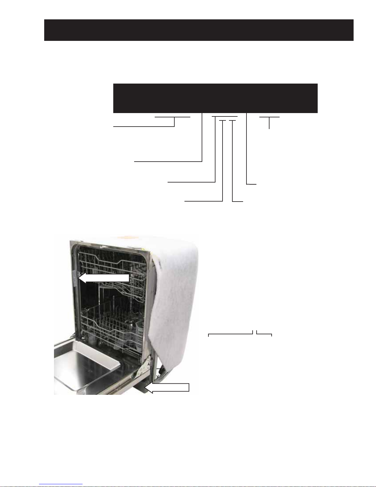
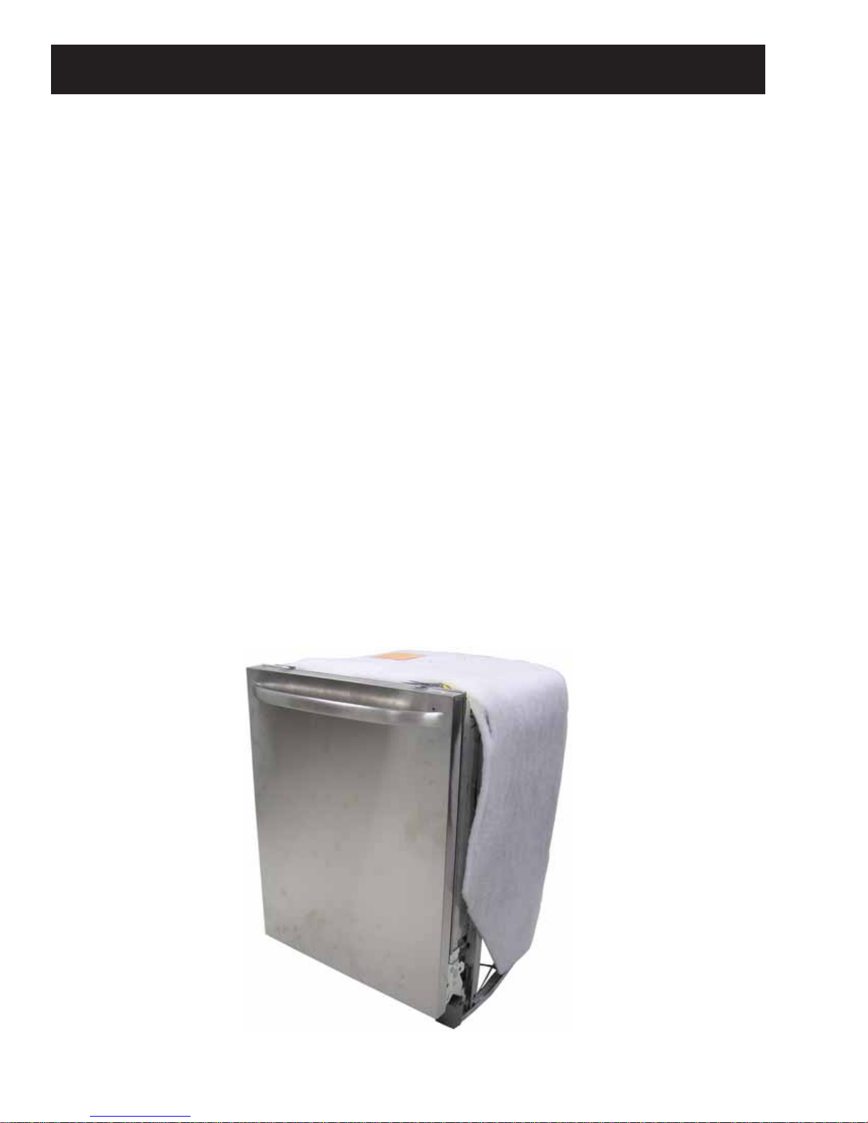
Nomenclature
G D W T 6 6 8 V B B
Exterior Color
BB = Black
CC = Bisque
SS = Stainless Steel
WW = White
Feature Pack
Nomenclature
Access Panel
The nomenclature plate is lo cat ed on
the left side of the tub wall, inside the
door jamb.
The mini-manual is located behind
the access panel.
Door
8 = Stainless Door
Model Year Designator
Handle/Control Location
0 = Latch/Front Control
6 = Recessed/Top Control
8 = Towel Bar/Top Control
Serial Number
The fi rst two characters of the serial number
identify the month and year of manufacture.
Example: VV123456S = November, 2011
V - NOV
Z - DEC
A - JAN
B - FEB
F - MAR
G - APR
H - MAY
L - JUN
M - JUL
R - AUG
S - SEP
T - OCT
2011 - V
2010 - T
2009 - S
2008 - R
2007 - M
2006 - L
2005 - H
2004 - G
2003 - F
2002 - D
2001 - A
2000 - Z
The letter des ig nat ing
the year re peats every
12 years.
Example:
V - 2011
V - 1999
V - 1987
– 5 –
Page 6
Introduction
New Features and Benefi ts
• Five-stage fi ltration with Piranha™ hard food disposer
• Dedicated silverware jets
• Steam PreWash
• Fan assist dry with heated option and ActiveVent
• Fifty-two dBA sound level
• ENERGY STAR® qualifi ed and CEE Tier II rated
• SmartDispense™ (only on models GDWT7XX, PDWT3XX, PDWT5XX, CDWT980, and ZBD89XX)
Weights and Dimensions
Approximate Shipping Weight .........................................................................................................................................115 lb
Net Weight .................................................................................................................................................................................110 lb
Overall Height ..........................................................................................................................................................................34 in.
Height with Legs Extended ................................................................................................................................................35 in.
Overall Depth ...........................................................................................................................................................................24
Overall Width ............................................................................................................................................................................24 in.
3
/4 in.
– 6 –
Page 7
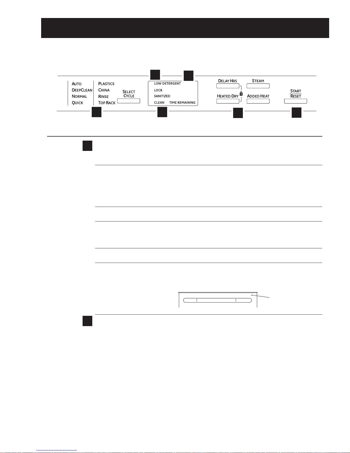
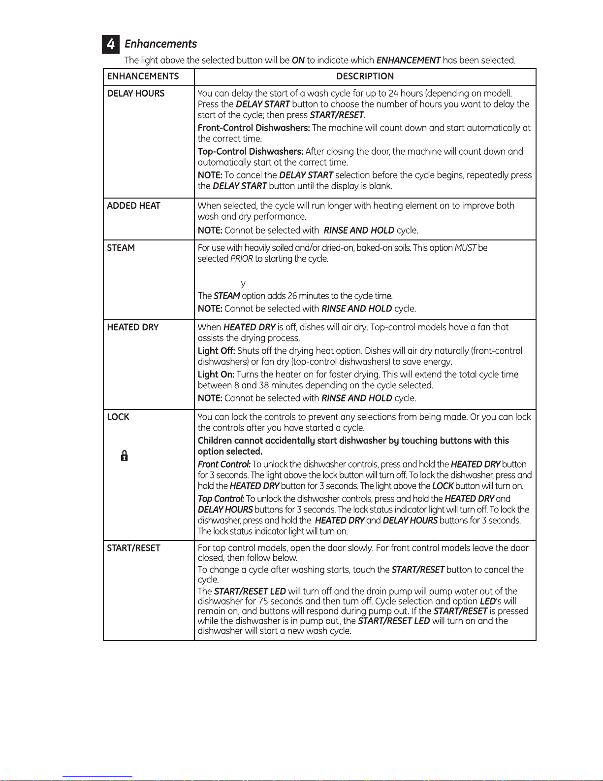
Control Features
Throughout this manual, features and appearance may vary from your model.
Top-Control Dishwashers
3
Control Settings
Status Indicator Lights (Indicators vary by models)
1
The Status display tells you what is happening while the dishwasher is in operation and may flash, indicating
a malfunction. The lights will come ON indicating the sequence of the dishwasher operation.
LOW DETERGENT Displayed when the SmartDispense
1
6
dishwasher detergent.
NOTE:If you are not using SmartDispense
LED light off, press the ADDED HEAT button 5 times within 3 seconds. You will hear 3
beeps; then the light will go off. You can turn the light back on by pressing the ADDED
HEAT button 5 times within 3 seconds.
SENSING Displayed while the Clean Sensor
of water. The dishwasher will adjust the selected cycle to achieve optimal performance.
SANITIZED Displayed at the end of the cycle when SANITIZE has been selected and the dishwasher
has met the requirements for sanitization. See SANITIZE, below, for complete cycle
description. Opening the door or pressing any key while the door is closed and latched
will turn off the light.
CLEAN Displayed when a wash cycle is complete. Refer to Item 6, page 9, for further
explanation of clean light operation
CYCLE ST ATUS The cycle status indicator light is located on the right side of the dishwasher, above the
INDICAT OR handle. This light comes on as amber while the selected cycle is running. The light turns
to green when the selected cycle is complete. The light stays ON as green as a reminder
that the dishes are clean until the door is opened or until another cycle is selected.
2
4
TM
needs to be refilled with liquid or gel automatic
TM
and you want to turn the LOW DETERGENT
TM
is measuring the amount of soil and temperature
5
Time Remaining Display (on some models)
2
During operation, the display shows the minutes remaining until the cycle is complete. The display may
adjust the remaining time while the Sensing light is on. The time displayed at the start of each cycle may
change from the factory setting as the unit customizes itself to home use. During a delay start, the display
will show hours of time remaining until the cycle starts.
NOTE: This dishwasher is equipped with CleanSensor
6
cycle length and time may vary depending on soil and water temperature conditions.
– 7 –
Cycle Status Indicator Light
TM
with automatic temperature control; therefore,
(Continued next page)
Page 8
– 8 –
(Continued next page)
Page 9
The STEAM option will use the heater to
increase the temperature of the water. The circulation pump will turn off
periodicall , allowing water to drip onto the hot calrod which will create steam.
– 9 –
(Continued next page)
Page 10
Start
5
– 10 –
Page 11

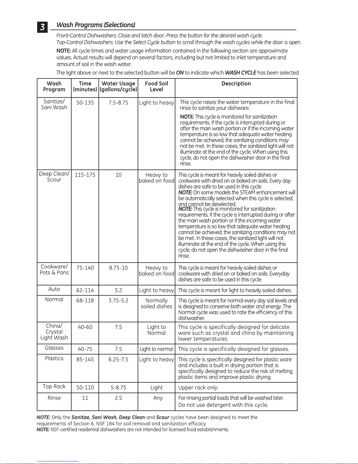
Cycles
Auto Hot Start:
Auto Hot Start is initiated by the control board when it senses water temperature is below 80°F. If the water
is below 80°F after prewash, the unit circulates for 1 to 5 minutes (depending on the cycle selected) and then
drains for 75 seconds. This procedure repeats up to 4 times or until the water reaches 80°F.
Added Heat:
The added heat option differs for the various cycles. Some cycles will not be modifi ed, some cycles will
increase the calrod time, and some cycles will get additional segments added (e.g., AUTO has 6 segments
without added heat and 9 segments with added heat).
Heated Dry:
During HEATED DRY, the heater cycles at a rate of 60 seconds on and 51 seconds off.
Cycle Explanations and Exceptions:
• Turbidity Response is used during the SANITIZED, NORMAL, and AUTO cycles only.
• Timed cycles can change depending on the water temperature. If the minimum temperature is not met,
an extended time is added until the temperature is met or the time expires.
• Partial Drain and Fill Algorithm is used during NORMAL and AUTO cycles only.
• Auto Hot Start may cause the fi rst prewash to repeat up to 4 times.
• Disabling STEAM will shorten the cycle time.
• If STEAM is selected during NORMAL or AUTO cycles, turbidity response is ignored, and cycle defaults to
the heavy soil algorithm.
• HEATED DRY takes 34 minutes for the NORMAL cycle while the other cycles vary to as long as 60
minutes for PLASTICS. There is no HEATED DRY for the RINSE cycle.
• Drain Overlap is a short period when both the wash and drain pumps run simultaneously as the
circulation cycle ends and draining begins.
• Drain Pause is a short period between the circulation cycle ending and the drain starting.
• Extend Times enables both the circulation pump and heater to operate simultaneously.
Turbidity Response
The turbidity response is measured in DC volts. Four to 5 VDC registers light soil and a shorter wash cycle,
while 0 to 2 VDC registers heavy soil and a longer wash cycle. SANITIZED wash measures the turbidity
response during the third prewash cycle and adjusts the time based on these measurements. NORMAL wash
measures the turbidity response during the fi rst prewash and the prewash before the main wash. If a clean
response is measured during the fi rst prewash, the cycle advances directly to the main wash with no drain or
fi ll. If a clean response is measured during the prewash before the main wash, the control shortens the active
heater time.
– 11 –
Page 12
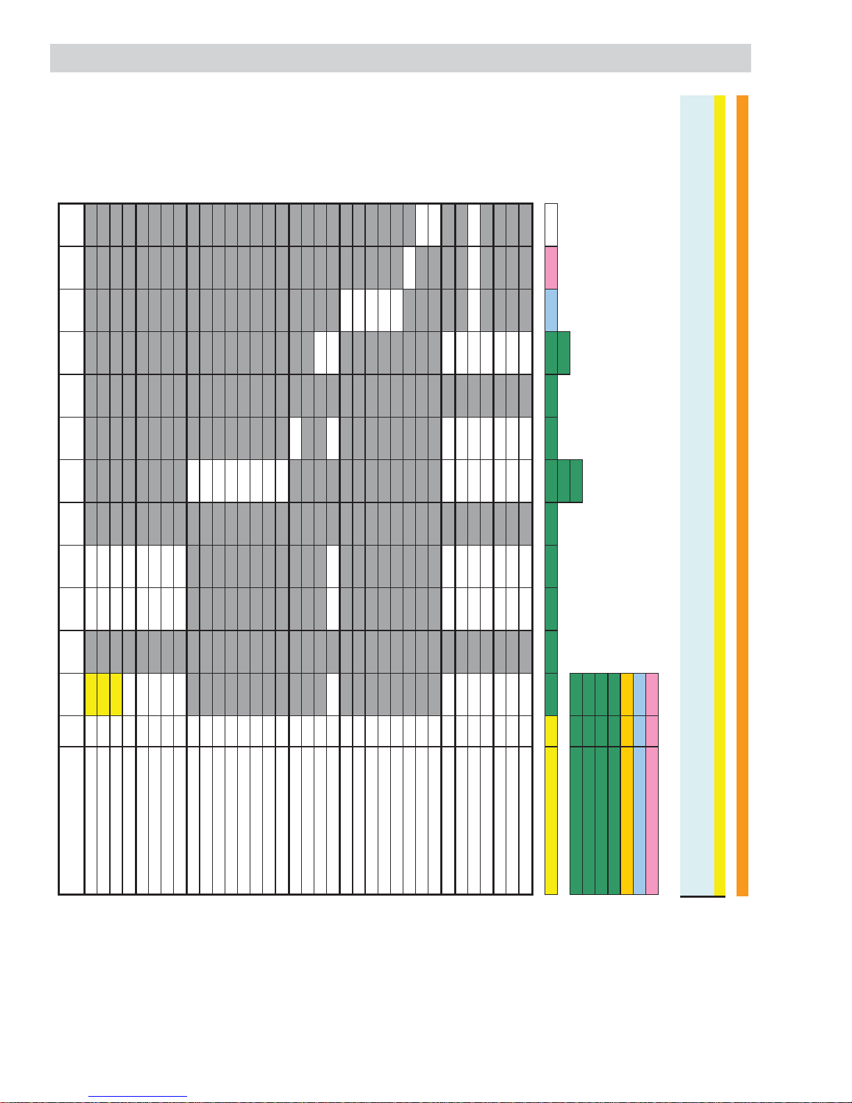
Normal Cycle PW1* PW2 PW3 PW4 PW5 MW** PR 1 PR2 FR Dry
Cool-
Down
Turb DOE [Vdc] 3.1 - 5.0 5.0 - -
Turb MIN [Vdc] 2.1 - 5.0 5.0 - -
Turb MED [Vdc] 2.1 - 5.0 5.0 - -
Turb MAX [Vdc] 1.0 - 0.1 0.1 - -
Time DOE [min] 5 - - 10 - -
Time MIN [min] 5 - - 10 - -
Time MED [min] 5 - - 10 - -
Time MAX [min] 1 - 3 10 - -
MW DOE Circulate Time [min] - - 30 -
MW DOE Heater Time [min] - - 28 -
MW MIN Circulat e Time [min] - - 30 -
MW MIN Heater Time [min] - - 27 -
MW MED Circulate Time [min] - - 30 -
MW MED Heater Time [min] - - 27 -
MW MAX Circulate Time [min] - - 30 -
MW MAX Heater Time [min] - - 30 -
Pre-Rinse 1 (PR 1) [min] - - 7 -
Pre-Rinse 2 (PR 2) [min] - - -
Final Rinse (FR) [min] - - - 6
Heater On Time [min] 0 - 0 10 - y** 0 - 5
Dry Time (Total Time) w/ HD [min] - - - 34
HD - Initial ON Time [min[ - - - 4
HD - Pulse OFF Time [sec] - - - 105
HD - Pulse ON Time [sec] - - - 75
Dry Time (Tot al Time) w/o HD [ min] - - - 0
Cool-Down Time [min] - - - 14
Fan Time w/ Heated Dry [min] - - - 48
W/ Out Heated Dry [min] - - - 14
Pause time (circ t o drain) [sec] 0 - 15 0 - 15 0 - 15
Fill Time (low flow water valve) [sec] 62 - 16 62 - 21 62 - 23
Fill Time (high flow water valve) [sec] 46 - 13 46 - 15 46 - 17
Drain Time [sec] 7 - 75 10 - 75 11 - 105
Max Temp Limit [F] - - - 158 - 158 - - 158
Min Temp Limit [F] ----- 120 - - 120
Extend Time [min] 0 - 0 0 - 5 0 - 5
Total Primiti ve [min] 6.15 - 4.52 11.20 - 31.25 8.22 - 8.13 34.00 14.00
31.60 13.13
Shortest Cycle [min] 67.63 36.60
Longest Cycle [min] 93.82
ART (Max) [min] 69.82
ART (Med) [min] 69.82
AH-MW [min] NA
HTD [min] 34.00
CD [min] 14.00
* IF on PW1 the turbidity is greater than the DOE response the cycle will skip the drain portion of PW1, completely skip PW3, PW4, and skip the fill into MW…effectively merging PW1 and MW circ
* IF on PW1 the turbidity is less than the DOE response but greater than the MI N response the cycle will skip PW3, PW4.
** Circulation and Heater ON times for Main Wash are determined by the turb valies in PW1
*** Detergent/Rinse Aid relay will be activated in FR
NOTE: ****PW2, PW5, PR2 intent ionally left blank due to separating the added heat functionality into its own cycle definition table. See Norm_Auto+AH cycle table.***
Cycle Chart
Fan
– 12 –
Page 13
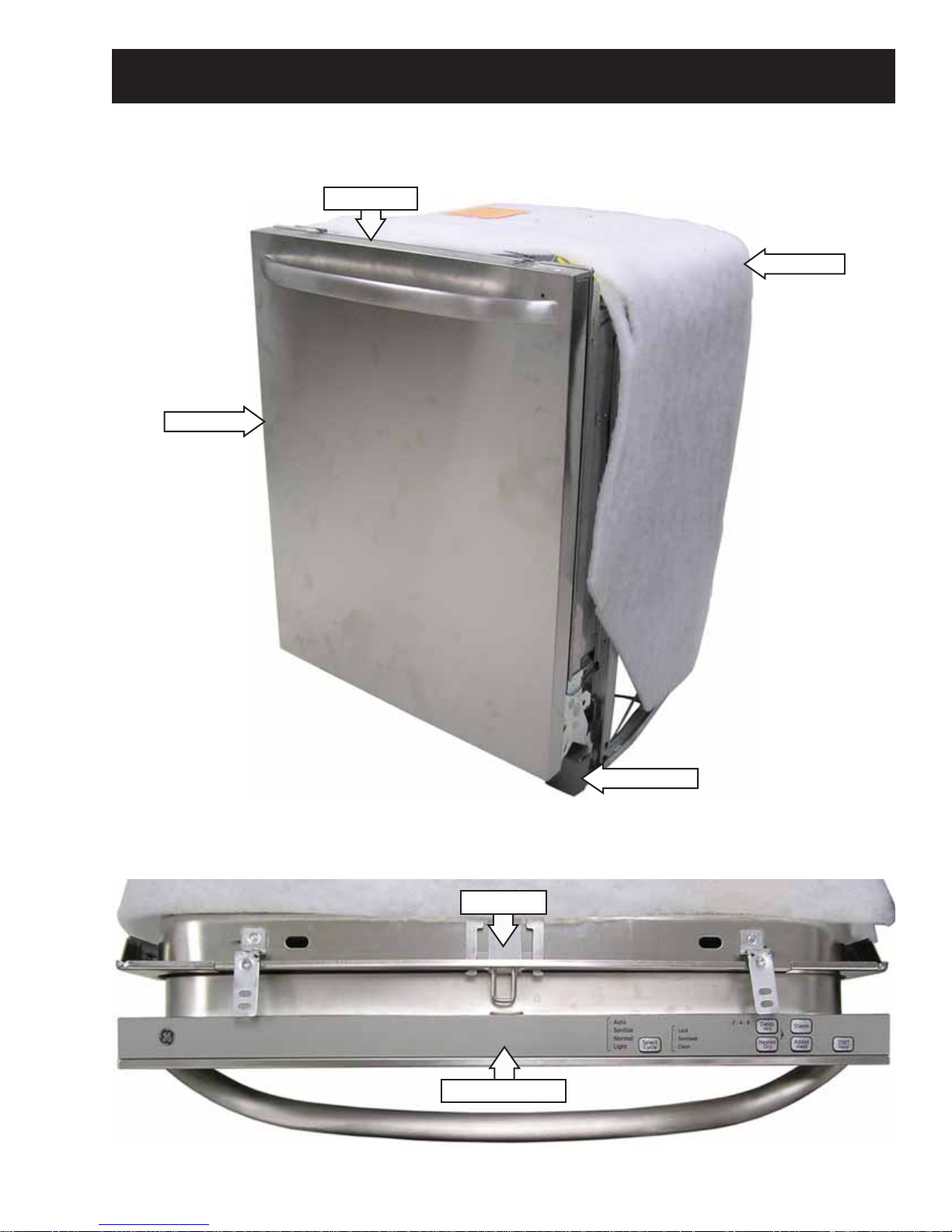
Front View
Door Panel
Component Locator Views
Control Panel
Insulation
Control Panel View
Access Panel
Door Latch
Control Assembly
(Continued next page)
– 13 –
Page 14

Interior View (Without Racks)
Detergent/Rinse Module Compartment View
Detergent Compartment
Detergent/Rinse Module
Vent
Rinse Agent Outlet
Indicator Window
Rinse Agent Cap
Compartment Lid
– 14 –
(Continued next page)
Page 15

Interior View of Basin (With Racks Removed) Left Side View (Insulation Removed)
Spray Arm
Coarse Filter
Float Dome
Heating Element
Fill Hose
Hub Nut
Fine Filter
Bottom View (Looking Up)
Front
Overfi ll Switch
Water Valve
Fill Funnel
Door Spring
Tub TCO
Drain Pump
Back
Motor Pump Assembly
Turbidity Sensor
Sump
Heater
– 15 –
Page 16

Control Board Connector Locator View
J2
J7
J5
J1 - Power Supply
J2 - Power Switching
J3 - Turbidity/Temperature Sensor
J3
J1
J5 - Active Vent
J7 - Keypad
– 16 –
Page 17

Dishwasher Components
Outer Door Panel
The outer door panel must be removed to access
the control board, detergent/rinse module, control
TCO, tactile switch, door switch, vent, and lens.
To remove the outer door panel:
1. Remove the two 1/4-in. hex-head screws from
the bottom of the front door panel (one on each
side).
3. Remove the single Phillips-head screw from the
control cover.
4. Disconnect the wire harness from the tactile
switch.
2. Remove the ten T-15 torx screws from the outer
door panel.
Caution: Carefully remove the outer door from the
inner door frame.
Disconnect
Water Hardness Test and Calibration
Test Water Hardness
The automatic liquid dishwasher detergent
dispenser (SmartDispenseTM) dispenses the optimum
amount of detergent to clean the dishes. The
amount of detergent introduced during each cycle
is based on the soil level of the dishes and the
hardness of the water. Therefore, the correct water
hardness setting is very important for both optimum
cleaning of dishes and detergent usage.
– 17 –
(Continued next page)
Page 18

Prior to its fi rst use, the dishwasher must be
calibrated for water hardness. This process requires
the use of a water hardness test strip (Part #
WD01X10295).
Test water hardness following the instructions on
the test strip package shown above.
1. Press the SELECT CYCLE and DELAY HRS
buttons simultaneously and hold for 3 seconds.
2. The current hardness setting is shown on the
TIME REMAINING display.
3. Enter the value from the test strip using the
STEAM button to increase the value or the
SELECT CYCLE button to decrease the value.
4. Press the START/RESET button to return the
dishwasher to normal operation. The last
displayed value is saved as the water hardness
value.
The 4 light green stripes on the test strip change
color depending on the water hardness. The harder
the water, the more stripes change from green to
red.
Note: If all stripes remain green after the test, the
outcome is "0 RED." The value to be entered into the
dishwasher is "1."
Convert the test reading according to the table
below.
Water Hardness Test Strip Indication
Red Stripes on Strip Value to Enter into Dishwasher
01
12
23
34
45
Note: 1 grain per gallon = 17.1 parts per million.
SmartDispense
TM
SmartDispense is a bulk liquid detergent dispenser
assembly consisting of the following components:
• Detergent Reservoir – Mounted within the inner
door panel.
• Detergent Level Sensor – Connected to a LOW
DETERGENT LED on the control panel.
• Positive Displacement Pump – Injects
the optimal amount of detergent into the
dishwasher during each cycle.
Detergent Reservoir
Note: The SmartDispense system can only be used
with liquid or gel automatic dishwasher detergent.
To access the reservoir, push down on the cap
covering the reservoir to engage the ratchet, then
turn it counterclockwise to open.
To enter water hardness value (on some models):
Note: Dishwasher must be in standby mode. Press
the SELECT CYCLE button to activate the tactile
switch and illuminate the lights on the control panel.
– 18 –
(Continued next page)
Page 19

Position the door at a 30- to 45-degree angle. Fill
LOW DETERGENT
SmartDispense
S
ENSING
W
ASHING
D
RYING
S
ANITIZED
C
LEAN
Light will
turn on
when time
to refill
the reservoir with a liquid automatic dishwasher
detergent until the detergent reaches the threads
of the reservoir access. The dispenser tank holds
approximately 45 ounces of liquid dishwasher
detergent (about 1 to 2 months' supply).
Place the cap on the reservoir access threads, push
down, and then turn clockwise until the cap is tight.
To remove the detergent reservoir:
Note: Removing the reservoir access collar causes
structural damage to the collar. It must be replaced
with a new part (Part # WD35X10059).
Remove the outer door panel. (See Outer Door
Panel.) Insert a small, fl at blade screwdriver into the
slot in the side of the retaining collar and push the
screwdriver handle counterclockwise while turning
the reservoir access collar counterclockwise a
quarter turn. Remove the retaining collar. Unplug the
tube from the reservoir outlet and disconnect the
sensor from the control module.
Detergent Level Sensor
The SmartDispense detergent level sensor consists
of a single-level detection continuity sensor and
includes the following components:
• A grommet seal
• A LOW DETERGENT LED indicator light
• A wire harness
When the detergent in the reservoir drops below
the continuity sensor, a signal is sent to the control
board, and the LOW DETERGENT LED indicator light
is turned on. The light indicates 3 to 7 wash cycles
are left before the detergent reservoir is completely
empty.
Note: The LOW DETERGENT LED may look like it
is illuminated when in fact it is not. An illuminated
indicator shines bright red.
Note: If the SmartDispense system is not being
used, the LOW DETERGENT light can be turned off
(or on) by pressing the ADDED HEAT button 5 times
within 3 seconds. There are 3 audible beeps when
the light goes off.
The sensor is similar to the type used in several
automotive applications, such as the windshield
wiper fl uid reservoir.
Note: The dispenser tank comes as an assembly.
It includes the sensor with wire harness, gasket,
and retaining collar. The complete assembly part
number is WD35X10058.
The control takes a reading of the detergent level at
power-up (when power is restored from an outage)
and each time the door is closed and latched.
The control outputs a pulsing 5-VDC analog signal
to the sensor and monitors the return voltage.
Changes in the quantity of detergent in the tank
change the amount of current drawn by the sensor.
(Continued next page)
– 19 –
Page 20

The routing of the DC wiring from the tank is very
123 4
133414957
2 35.4 43.4 51.4 59.4
3 37.8 45.8 53.8 61.8
4 40.2 48.2 56.2 64.2
5 42.6 50.6 58.6 66.6
Smart Dispense Bottle Duration
123 4
1 10.3 8.3 6.9 5.9
2 9.6 7.8 6.6 5.7
3 9.0 7.4 6.3 5.5
4 8.4 7.0 6.0 5.3
5 8.0 6.7 5.8 5.1
Dosage (ml)
Hardness
Soil Level
Hardness
Bottle Duration (wks)
Soil Level
important. The 3 tape points on the tank keep the
DC wiring perpendicular to the AC harness wiring
running down across the front of the tank.
The dispenser pump operates on 120 VAC. During
each prewash cycle, the pump is energized for 5
seconds, dispensing 4 ml of detergent.
The electronic control uses two inputs to determine
the total amount of detergent dispensed during the
main wash cycle:
Tape Point
Tape Point
Tank
Tape Point
Sensor and Gasket
Note: The dispenser tank, sensor with wire harness,
and gasket are only available as a complete
assembly (Part # WD35X10058). They are shipped
with a new dispenser tank retaining collar.
• Soil level determined by the turbidity sensor
• Water hardness as calibrated for the location
A water hardness selection mode permits the
calibration of the water hardness for the location
at installation. (See
Calibration.)
Water Hardness Test and
To determine the amount of detergent to dispense
during the main wash, the electronic control uses
the following formula:
4 ml x Number of Prewashes
+ 25 ml + Additional Quantity for Hardness
The additional quantity is a predefi ned quantity
of detergent based on the water hardness level
programmed into the control.
Approximate Detergent Use
SmartDispense Dosage Amount
Smart Dispense Dosage Amount
Detergent Level Sensor Strip Circuit
DETERGENT
BRN/YELLOW RED
J4-1
SENSOR
Positive Displacement Pump
The SmartDispense positive displacement pump
consists of a continuous fl exible tube running from
the detergent reservoir to the inner door detergent
outlet. The tube runs around the inside edge of the
pump housing. A 3-roller impeller fi ts tightly into
the center of the pump housing, with each of the
3 rollers squeezing the sidewall of the tube. As the
impeller is driven counterclockwise by the motor, it
squeezes out a predetermined amount of detergent
for each 1/3 revolution of the impeller.
Pump
Housing
Impeller
J4-3
SmartDispense Bottle Duration
From
Detergent
Reservoir
To Detergent
Outlet
(Continued next page)
– 20 –
Page 21

To remove the positive displacement pump:
1. Remove the outer door panel. (See
Panel.)
Outer Door
2. Remove 2 Phillips-head screws from the lower
right side of the door edge to release the pump
bracket.
A chemical reaction also takes place between the
chlorine detergent and the enzyme detergent,
which causes the two liquids to coagulate and
build up around the detergent level sensor. This
buildup may prohibit the sensor from sending the
low-detergent signal to the control board, and the
LOW DETERGENT light will not illuminate when the
dispenser tank is empty.
Consumer Purge Cycle
The consumer must enter service mode to activate
the purge cycle. (See
Service Mode.) The purge cycle
fi lls the dishwasher for 57 seconds, then energizes
the dispenser pump (instead of the main motor)
continuously to drain the dispenser tank.
The purge cycle deselects all other options and
runs for 65 minutes. The consumer should run the
purge cycle 3 times, fi lling the dispenser tank with
water for the second and third cycles. Total time is
approximately 3 hours.
3. Remove the grommet from the inner door panel
and unplug the tube from the reservoir outlet.
4. Disconnect the wires and remove the pump.
Positive Displacement Pump Strip Circuit
BULK DETERGENT
PUMP
M
875 Ω
J2-1
ORANGE
Consumer Purge of the Bulk Dispenser Tank
When to Purge the Bulk Dispenser Tank
Only liquid or gel automatic dishwasher detergent
can be used in the dispenser tank. The dispenser
tank must be purged if the consumer puts hand
dishwashing detergent or a rinse agent in the
dispenser tank. These products produce copious
amounts of suds, and water leaks result every time
the dishwasher is run, until the dispenser tank is
emptied.
The dispenser must also be purged if a liquid
dishwasher detergent containing chlorine (like
Cascade Pure Rinse Formula) and one containing
enzymes (like Cascade Complete) have been mixed
in the dispenser tank. When this happens, the
chlorine destroys the enzymes, resulting in poor
wash performance. You can tell if the detergent
contains chlorine or enzymes by reading the
content label on the container.
To purge the bulk dispenser tank (on some models):
1. Make sure STEAM, ADDED HEAT, and HEATED
DRY LEDs are off.
2. Press HEATED DRY button and SELECT CYCLE
button simultaneously for 3 seconds. If done
correctly, all the LEDs illuminate.
WHITE
3. Press SELECT CYCLE button and ADDED HEAT
button simultaneously for 3 seconds. If done
correctly, the AUTO and LOCK LEDs illuminate.
4. Press START/RESET button one time to exit
service mode.
5. Press START/RESET button to start an auto
cycle and make sure STEAM, ADDED HEAT, and
HEATED DRY LEDs are off.
6. Dishwasher runs a complete cycle with the
main motor instead of the dispenser tank. Cycle
is complete when the CLEAN light illuminates.
This should take approximately 60 minutes.
7. Open door and wipe up the excess detergent
from the door and tub.
8. Pour water on the door and tub where there is
detergent residue.
9. Remove SmartDispense cap and fi ll dispenser
tank with water. Replace the cap.
(Continued next page)
– 21 –
Page 22

10. Repeat steps 1 thru 9 one time.
11. Repeat steps 1 thru 6. When the CLEAN LED
illuminates, the system is purged and ready to
be refi lled with the correct detergent.
Control Thermal Cutout (TCO)
The control TCO is one shot with a trip temperature
of 250°F. If the control TCO trips, no voltage is
supplied to the control board or components.
Look for control or wire damage and replace as
necessary.
To remove the control TCO:
1. Remove the outer door panel. (See
Panel.)
2. Remove the T-15 torx screw from the control
TCO.
Outer Door
Control Board
The control board is attached to the right side of the
inner door panel.
Voltage from the control board to the turbidity
sensor can be tested by checking the voltage at J3
on the control board. (See Control Board Connector
Locator View.) A pulsed 2-VDC signal should be
measured across wires J3, pin 2 (dark blue wire), and
J3, pin 3 (gray wire).
Control Board Turbidity Sensor
YB
1
TURBIDITY/
TEMPERATURE
SENSOR
J3
NX
2
SX
3
OX
4
To remove the control board:
1. Remove the control TCO. (See
2. Disconnect the 4 wire harnesses from the
control board.
NTC
1
RECEIVER EMITTER
2
TRANSMITTER
3
CATHODE
4
Vcc
Control TCO.)
Control TCO
Note: When replacing the control TCO, splice a new
thermostat into the harness using connectors and
procedures approved for damp/wet conditions.
Silicone Grease
Disconnect
Disconnect
Disconnect
3. Remove the Phillips-head screw holding the
control board to the inner door panel.
– 22 –
(Continued next page)
Page 23

4. Disengage the control board tabs from the inner
door panel.
Lens
The lens is located behind the console and attached
to the front panel with double-back tope. A new lens
comes with the console as a kit.
Tab
Tab
Tactile Switch
The tactile switch includes a silicone pad to protect
the switch from moisture. The tactile switch buttons
and silicone pad come as an assembly.
To remove the tactile switch:
1. Remove the outer door panel. (See Outer Door
Panel.)
To remove the lens:
1. Remove the outer door panel. (See Outer Door
Panel.)
2. Remove the single Phillips-head screw from the
console.
3. Pull the console out of the door.
2. Remove the 2 Phillips-head screws and the
tactile switch from the console.
Note: When replacing the tactile switch, transfer the
model select plug to the new switch.
Model Select Plug
Note: The tactile switch buttons are keyed to fi t in
the proper place on the silicone pad.
Silicone Pad
Console
4. Pry the lens off the door panel with a fl at blade
screwdriver.
Lens
Tactile Switch Buttons
– 23 –
Page 24

Door Handle
The door handle is held in place by 2 screws that
can be accessed by removing the console.
To remove the door handle:
3. Disconnect the 2 wires from the door switch.
1. Remove the console. (See
Lens, steps 1-3.)
2. Remove the two 1/4-in. hex-head screws
holding the handle to the outer door (1 on each
side).
Disconnect
Disconnect
4. Remove the 3 Phillips-head screws from the
door switch.
Door Switch Assembly
The door switch assembly is activated by a springloaded plunger that connects or disconnects the line
(hot) side of 120 VAC.
When the door is in the closed position, the door
latch presses and holds down the switch plunger on
the door switch assembly. This action holds the door
fi rmly against the seal, with the contacts of the door
switch closed.
To remove the door switch assembly:
1. Disconnect the power supply to the dishwasher.
2. Remove the outer door panel. (See Outer Door
Panel.)
Detergent/Rinse Module
The inner door panel must be removed to access
the detergent/rinse module. (See Inner Door Panel.)
The detergent/rinse module is connected by 2 wires
and held in place by 6 Phillips-head screws and a
bracket.
The detergent/rinse module operates on 120 VAC
and has an approximate resistance value of 1.2 to
2.8 K
Bracket
– 24 –
(Continued next page)
Page 25

The detergent/rinse mod ule au to mat i cal ly
dis pens es both de ter gent and rinse agent at the
ap pro pri ate times. The module is activated twice
during a wash cycle. Detergent is dispensed at the
beginning of the main wash cycle and rinse agent at
the beginning of the fi nal rinse.
Operation of the detergent/rinse module can be
checked by using the service test mode. (See Service
Mode.)
The fi rst time the module is activated, the lever
slides up the right-hand path of the connecting rod
(1). This action releases the de ter gent cover.
1
Vent Fan
The vent fan runs at the end of the dry cycle,
whether HEATED DRY has been selected or not. It
will run for 1 to 15 minutes when not in HEATED
DRY and 30 to 50 minutes during some HEATED
DRY cycles. The vent is located on the upper-left
side of the inner door panel and has a resistance of
65 .
To remove the vent fan:
1. Remove the outer door panel. (See Outer Door
Panel.)
2. Disconnect the vent fan wire harness.
When the module is deactivated, the lever returns
down the left-hand path and comes to rest under
the notch (2) in the center of the connecting rod.
2
At the second activation of the module, the lever lifts
the con nect ing rod by the notch. This action lifts the
rinse dispenser plunger (3) and re leas es the rinse
agent. When the module is deactivated, the lever
returns to its original start ing position.
Disconnect
3. Remove the 4 Phillips-head screws from the
vent fan and lift it off the conduit exhaust.
3
Conduit
(Continued next page)
– 25 –
Page 26

4. Remove the 4 Phillips-head screws from the
back of the vent fan.
5. Remove the 2 Phillips-head screws from the
bottom of the vent fan.
3. Remove the single Phillips-head screw from the
vent switch housing.
Inner Door Panel
To remove the inner door panel:
Active Vent
The active vent is attached to the inner door panel
between the vent and door switch. It operates on 12
VDC and has a resistance of 103 The vent motor
turns the active vent switch clockwise to close the
vent and counterclockwise to open the vent.
To remove the active vent:
1. Remove the vent fan. (See Vent Fan, steps 1-3.)
2. Disconnect the active vent wire harness.
1. Remove the control TCO. (See Control TCO.)
2. Disconnect 3 wire harnesses from the control
board.
Disconnect
Disconnect
Disconnect
Disconnect
– 26 –
(Continued next page)
Page 27

3. Disconnect the 2 detergent/rinse module wires
and the vent fan wiring harness.
Bottom Door Seal
The bottom door seal is riveted to the inner door
panel. To remove the bottom door seal, replace the
inner door panel. (See Inner Door Panel.)
Disconnect
Disconnect
4. If the installation allows, pull the dishwasher out
to access the door hinges.
5. Insert 2 screwdrivers (1 on each side) thru the
door hinge bracket holes and secure them
under the dishwasher tub.
Tub Gasket
The dishwasher tub gasket prevents water leakage
and fi ts in a channel that lines the rim of the
dishwasher tub. The gasket uses a wire rod that
provides tension to the seal.
To remove the tub gasket:
1. Remove the outer door panel. (See Outer Door
Panel.)
2. Pull the wire rod out of the gasket.
Gasket
6. Remove the 4 Phillips-head screws holding the
inner door panel to the door hinges (2 on each
side).
7. Slide the inner door panel off the door hinges.
Wire Rod
3. Remove the dishwasher tub gasket by grasping
an end and peeling it away from the channel.
Channel
Tub Gasket
Caution: When installing the tub gasket, run your
fi nger over the gasket, assuring it is smooth and
even for a proper seal.
– 27 –
Page 28

Center Wash Arm
Lower Wash Arm
To remove the center wash arm:
1. Disengage the left upper rack slide by pressing
the lever down while pulling the rack out.
2. Disengage the right upper rack slide by pressing
the lever up while pulling the rack out.
The lower wash arm can be accessed by opening
the dishwasher door and removing the bottom rack.
Remove the lower wash arm by pulling it up while
turning it counterclockwise.
Upper Wash Arm
Remove the upper wash arm by removing the 1/4in. hex-head screw holding the arm to the conduit.
3. Remove the 1/4-in. hex-head screw from the
center wash arm.
– 28 –
Page 29

Fine Filter
To remove the fi ne fi lter:
4. Pull the 2 clip hinges (1 on each side) outward to
release the conduit tabs.
1. Remove the lower wash arm. (See
Arm.)
Lower Wash
2. Rotate the hub nut counterclockwise. Lift the
hub nut off the fi ne fi lter.
Hub Nut
3. Lift the fi ne fi lter off the wash arm hub.
Tab
Clip
5. Lift the tab on the wash arm hub while pulling
the conduit back to remove it.
Conduit
Tab
Wash Arm Hub
Fine Filter
Sump Filter
The sump fi lter prevents large particles from
entering the sump.
To remove the sump fi lter:
1. Remove the upper rack. (See Center Wash Arm,
steps 1-2.)
2. Remove the upper wash arm. (See
Arm.)
3. Remove the fi ne fi lter. (See Fine Filter.)
Upper Wash
6. Release the 4 tabs on the sump fi lter cover to
remove it.
Sump Filter Cover
– 29 –
(Continued next page)
Page 30

7. Release the 2 sump fi lter tabs with a fl at blade
screwdriver or putty knife.
Coarse Filter
To remove the coarse fi lter:
Tab
Sump Filter
1. Remove the sump fi lter. (See
Sump Filter.)
2. Turn the wash arm hub counterclockwise and
remove it from the tub.
3. Lift the coarse fi lter from the dishwasher.
Tab
8. Remove the sump fi lter by pulling it up and to
the right.
Coarse Filter
Note: Insure the wash arm bearing is in the proper
location before assembly.
Bearing
– 30 –
Page 31

Float Switch
Turbidity Sensor
The fl oat switch activates if water reaches the
fl oat stem inside the dishwasher. The switch only
terminates the voltage to the water valve.
To remove the fl oat swit ch:
1. Remove the two 1/4-in. hex-head screws and
the access panel.
2. Disconnect the fl oat switch wire harness.
3. Remove the 2 Phillips-head screws holding the
switch to the dishwasher.
The turbidity sensor measures the amount of
suspended particles in the wash water in the sump.
The sump water lays within the 1/4- to 3/8-in. gap
between the LED transmitter and the receptor
during the designated fi lls. Successive turbidity
measurements are supplied to the control module
and used to determine whether to add or skip any
prewash or rinse cycles and whether to adjust the
wash or heat times. By measuring the turbidity level,
the control module can conserve energy on lightly
soiled loads by skipping unnecessary cycles. If the
soil level is high, the control module adds one or
more rinse cycles and increases the wash and heat
times as necessary.
Note: If the turbidity sensor fails, the unit operates
for the maximum amount of time, using the
maximum number of wash and rinse fi lls for the
selected cycle.
The turbidity sensor can be tested by checking the
resistance across the wires on the control board at
J3, pin 1 (yellow/black wire), and J3, pin 4 (orange
wire). (See Control Board Connect Locator View.) The
thermistor's resistance has a negative temperature
coeffi cient.
Disconnect
4. Pull the fl oat switch out of the bracket.
• At 75°F, the resistance is approximately 9.9 K.
• At 140°F, the resistance is approximately 2.8 K
Control Board Turbidity Sensor
TURBIDITY/
TEMPERATURE
SENSOR
J3
1
2
3
4
YB
NX
SX
OX
NTC
1
RECEIVER EMITTER
2
TRANSMITTER
3
CATHODE
4
Vcc
– 31 –
(Continued next page)
Page 32

To remove the turbidity sensor:
To remove the heating element:
1. Remove the dishwasher from its installation.
2. Lay the dishwasher on its back.
3. Disconnect the wire harness from the turbidity
sensor.
4. Loosen the 5/16-in. hex-head screw from the
hose clamp and pull the turbidity sensor out of
the sump.
Note: When installing the turbidity sensor, align the
sensor tab in the cutout before tightening the hose
clamp.
Disconnect
1. Remove the dishwasher from its installation.
2. Lay the dishwasher on its back.
3. Disconnect the 2 wires from the heating element
terminals.
4. Remove the 2 nuts holding the heating element
to the dishwasher housing.
Disconnect
Disconnect
5. Remove the lower wash arm. (See Lower Wash
Arm.)
Tab
Heating Element
The heating element maintains water temperature
during some wash and rinse cycles.
The heating element has an approximate resistance
value of 16 . It is rated at 835 watts in wet
conditions and 665 watts in dry conditions.
Operation of the heating element can be checked
using the service test mode. (See Service Mode.) Allow
1 or 2 minutes before opening the dishwasher door
and note if heat is present.
6. Release the heating element from the 2
retainers and remove it from the tub.
Caution: To prevent water leakage, assure the
O-rings are placed between the heating element
and tub fl oor before installing the heating element
nuts.
O-ring
– 32 –
Page 33

Fill Funnel
The fi ll funnel is mounted on the left side of the tub.
Its purpose is to provide a method for supplying
water for the wash and rinse cycles. The air gap
prevents wash water that has been siphoned from
fl owing back into the water supply system should
the water pressure drop to less than atmospheric
pressure. The fi ll funnel also allows air into the tub to
permit airfl ow for drying dishware.
To remove the fi ll funnel:
1. Access the fi ll funnel by carefully pulling the
dishwasher out from its installation.
2. Remove the fi ll funnel cap by rotating it
counterclockwise.
Caution: To prevent water leakage, assure the
O-ring is in place before installing the fi ll funnel.
O-ring
3. Pull the hose off the fi ll funnel.
Fill Funnel Cap
Hose
Water Inlet Valve
The water inlet valve is electronically controlled and
solenoid-operated. The fl ow of water is controlled by
a rubber fl ow washer capable of maintaining a fl ow
rate of 1.1 to 1.3 gallons per minute with incoming
water pressure of 20 to 120 psi. The water inlet valve
is attached to a bracket located on the left side of
the front brace.
The water inlet valve is energized forapproximately
21 to 62 seconds during each fi ll. See the cycle chart
for specifi c times during cycles. (See Cycle Chart.)
The water inlet valve has an approximate resistance
value of 0.725 to 1.2 K
Operation of the water inlet valve can be checked
by using the service test mode. (See Service Mode.)
To remove the water inlet valve:
1. Remove the two 1/4-in. hex-head screws and
the access panel.
Fill Funnel
– 33 –
(Continued next page)
Page 34

2. Disconnect the overfi ll switch wiring harness.
Disconnect
3. Remove the two 5/16-in. hex-head screws from
the water inlet valve bracket.
6. Remove the clamp and outlet hose from the
valve.
Clamp
Hose
4. Slide the bracket down to disengage the tab
that holds the bracket to the dishwasher frame.
Tab
5. Disconnect the wiring harness from the water
inlet valve.
7. Remove the 4 Phillips-head screws from the
water inlet valve bracket.
Caution: To prevent water leakage, assure the
O-ring is retained in the valve before installing the
bracket.
Disconnect
O-Ring
– 34 –
Page 35

Drain Pump Assembly
Motor Pump Assembly
The drain pump assembly is located under the tub
and operates on 120 VAC. It is energized for the fi rst
60 seconds of a new cycle and for approximately
105 seconds after the wash pump shuts down to
remove any water in the dishwasher sump. The
drain pump forces water out of the drain line. A
check valve fl ap on the drain pump prevents the
discharged water from entering the sump.
The drain pump has an approximate resistance
value of 30 .
Operation of the drain pump assembly can be
checked by using the service test mode. (See Service
Mode.)
To remove the drain pump assembly:
1. Disconnect power.
2. Remove the dishwasher from its installation.
3. Lay the dishwasher on its back.
4. Disconnect the 2 wires from the drain pump.
The motor pump assembly is located under the
tub behind the sump. The motor utilizes a start
capacitor rated at 10 fd. The motor rotates
clockwise (as viewed from the terminal end) and
draws approximately 1 amp at 120 VAC.
The motor pump assembly has an approximate
resistance value of 10 .
Operation of the motor pump assembly can be
checked using the service test mode. (See Service
Mode.)
To remove the motor pump assembly:
1. Disconnect power.
2. Remove the dishwasher from its installation.
3. Lay the dishwasher on its back.
4. Disconnect the wire harness from the motor.
5. Loosen the 5/16-in. hex-head screw, then pull
the drain pump off the sump.
Disconnect
Disconnect
Disconnect
5. Loosen the two 5/16-in. hex-head screws from
the hose clamps.
– 35 –
(Continued next page)
Page 36

6. Disengage the motor hanger arm to remove the
motor pump assembly.
Tub Thermal Cutout (TCO)
4. Slide the tub TCO off the bracket.
Tub TCO
Note: When replacing the tub TCO, splice a new
thermostat into the harness using connectors and
procedures approved for damp/wet conditions.
Silicone Grease
The tub TCO trips at 165°F and it auto resets at
150°F.
The tub TCO is located under the tub behind the toe
kick panel.
To remove the tub TCO:
1. Disconnect power.
2. Remove the two 1/4-in. hex-head screws and
the access panel.
3. Remove the two 1/4-in. hex-head screws and
the shield.
Shield
– 36 –
Page 37

Troubleshooting
Service Mode
The dishwasher is programmed with a service mode to aid the technician in troubleshooting it. Each
component can be cycled to detect if it is functioning correctly. Components are cycled by pressing buttons
on the control panel.
To enter the service mode:
• Put the dishwasher in standby mode.
• Press the HEATED DRY and SELECT CYCLE buttons simultaneously.
If performed correctly, the control board responds with two beeps, and all LEDs illuminate for 4 seconds. To
exit the service mode, press the START/RESET button at any time. The dishwasher will automatically exit
service mode if the control panel is inactive for 5 minutes.
Service Mode Control Operation:
When a control is activated in the service mode, the output continues to remain active until the maximum
time has expired or another button is pressed. Once the water valve is activated, the microprocessor must
perform a drain cycle to pump out the water before exiting the service mode.
Control Replacement/Calibration:
The dishwasher enters into the test/00 calibration mode when the unit is fi rst powered on. The door must be
closed and latched. Wait approximately 6 minutes for the second fi ll before canceling the cycle by pressing
the START/RESET button. The dishwasher will be ready to operate after the water is pumped out.
– 37 –
(Continued next page)
Page 38

Top-Control
Activates/Deactivates fan
(Hold both buttons simultaneously for 3
seconds)
– 38 –
Page 39

Factory Test Mode
The factory test mode initiates automatically upon installation of a new main control board.
Factory test mode (approximately 5 minutes total):
• All LEDs light (10 seconds).
• Close door.
• Vent opens, fan activates for 5 seconds, and vent closes (15 seconds).
• Detergent rinse module and water inlet valve are energized (45-65 seconds, depending on model).
• Main pump is energized (55 seconds).
• Turbidity sensor is calibrated and other checks occur (90 seconds).
• Drain pump is energized (75 seconds).
• When second fi ll starts, exit test mode by pressing the START/RESET button.
In some cases, it may be necessary to unplug the unit to exit the test mode. If the unit is left in factory test
mode, the dishwasher could run as long as 75 minutes before exiting.
Turbidity Sensor Replacement/Calibration:
When the main control board is replaced, the dishwasher starts a factory test mode when powered on.
During this test, the turbidity sensor is calibrated. If the turbidity sensor is replaced without replacing the
control board, the sensor may be calibrated manually by pressing the START/RESET button 100 times.
If the turbidity sensor fails, the control board uses the maximum wash/rinse cycles.
– 39 –
Page 40

Schematics and Wiring Diagrams
WARNING: Disconnect electrical power before servicing.
Caution: Label all wires prior to disconnection. Wiring errors can cause improper and dangerous operation.
Verify operation after servicing.
NTC
3
2
4
1
YB
SX
OX
NX
TURBIDITY SENSOR
J5-1
WX
BXBW
WX
WX
BX
WX
WX
WX
WX
WX
RX
STRIP CIRCUITS
YB
725-1200
J2-11
THERMOSTAT
1
SUPPLY
89
71011
6
5
4
3
2
1
23
1
23
1
10
9
8
67
5
4
23
1
VENT
2
FLOOD
WATER VALVE
DOOR
YX
NO
SWITCH
C
PX
J2-5
BX
K
INTERLOC
BW
GY RX
DOOR
NO COM
INTERLOCK
BW
DOOR INTERLOCK
J2-10
Vcc
NTC
RECEIVER EMITTER
TRANSMITTER
CATHODE
3
2
4
1
NX
2
1
TURBIDITY/
SX
3
TEMPERATURE
OX
4
J3
SENSOR
DETERGENT
CNO
3
2
J1
POWER
J2
POWER SWITCHING
J4
SENSOR
J10
PQA
CONTROL CIRCUIT BOARD
J8
3-DIGIT DISPLAY
J7
J5
KEYPAD
ACTIVE
1
M
10
PUMP
CIRCULATION
NX
J2-4
PUMP MOTOR
NO COM
SENSOR
DETERGENT
HEATING ELEMENT
VX VX
J2-6
HEATING ELEMENT
WX
1200-2800
DETERGENT MODULE
RY
NO
C
THERMOSTAT
VX
J2-7
DRAIN PUMP
3-DIGIT DISPLAY
VENT MOTOR
WX
M
30
RX
M
RX
J5-2
DRAIN PUMP
WX
WX
HEATING ELEMENT
VX VX
M
30
DRAIN PUMP
RX
J2-8
NO
C
THERMOSTAT
LETTERS COLOR
COLOR CODE
LETTERS COLOR
2
1
BX
DETERGENT MODULE
RY
DETERGENT MODULE
FLOOD
SWITCH
RED
GRAY
RXSXTXVXWX
LT. BLUE
BLACK
AXBXCXNXOX
J1
3
4
J2-9
5
WX
PX YX
TAN
N
BROW
6
FAN
1200-2800
FAN
725-1200
CIRCULATION
CNO
PURPLE
WHITE
YELLOW
YX
DK. BLUE
ORANGE
GX GREEN
7
8
WX
NR
PUMP
PINK
PX
RX
M
65
J2-3
XB
XW
WX
NX
THE "X" INDICATES ONE SOLID COLOR -
NO TRACER. WIRES WITH TRACER SHOW
DR Module
1200-2800
(CIRCULATION PUMP)
SX
WAX MOTOR
J2-2
NL1
YG
G
WX
M
10
FAN
NR
BOTH COLORS. EXAMPLE -WR IS WHITE
WITH RED TRACER.
(optional)
M
M
BULK DETERGENT PUMP
OX
BULK DETERGENT PUMP
J2-1
65
WAX MOTOR
(CIRCULATION PUMP)
875
WX
SX
SENSOR
DETERGENT
DETERGENT SENSOR
1200-2800
BULK DETERGENT PUMP
GY
J4-1 J4-3
WX
M
875
OX
VENT
ACTIVE
MOTOR
E
Y
K
P
A
D
M
RX
BX
– 40 –
DOTTED LINE INDICATES
THE FEATURE IS NOT ON
ALL MODELS.
Page 41

GE Dishwasher Warranty.
Warranty
All warranty service provided by our Factory Service Centers,
or an authorized Customer Care
on-line, visit us at GEAppliances.com, or call 800.GE.CARES (800.432.2737) in
the United States. In Canada, call 1.800.561.3344. Please have serial number
and model number available when calling for service.
®
technician. To schedule service,
Staple your receipt here.
Proof of the original purchase
date is needed to obtain service
under the warranty.
For The Period Of: GE Will Replace:
One Year Any part of the dishwasher which fails due to a defect in materials or workmanship. During
From the date of the this limited one-year warranty, GE will also provide, free of charge, all labor and in-home service
original purchase to replace the defective part.
Five Years The dishwasher racks and the electronic control module if they should fail due to a defect
(only for model numbers in materials or workmanship. During this five-year limited warranty, you will be responsible
beginning with PDW for any labor or in-home service costs.
or CDW) From the date
of the original purchase
Lifetime of Product The Stainlesstub or door liner, if it fails to contain water due to a defect in materials or
(only for model numbers workmanship. During this limited warranty, GE will also provide, free of charge, all labor and
beginning with PDW in-home service to replace the defective part.
or CDW)
What GE Will Not Cover (for customers in the United States):
■ Service trips to your home to teach you how to use
the product.
■ Improper installation, delivery or maintenance.
■ Failure of the product if it is abused, misused, or used for
other than the intended purpose or used commercially.
■ Replacement of house fuses or resetting of circuit breakers.
■ Product not accessible to provide required service.
■ Damage to the product caused by accident, fire, floods
or acts of God.
■ Incidental or consequential damage caused by possible
defects with this appliance.
■ Cleaning or servicing of the air gap device in the drain line.
■ Damage caused after delivery, including damage from
items dropped on the door.
EXCLUSION OF IMPLIED WARRANTIES—Your sole and exclusive remedy is product repair as provided in this Limited
Warranty. Any implied warranties, including the implied warranties of merchantability or fitness for a particular
purpose, are limited to one year or the shortest period allowed by law.
This warranty is extended to the original purchaser and any succeeding owner for products purchased for home use within the
USA. If the product is located in an area where service by a GE Authorized Servicer is not available, you may be responsible for a trip
charge or you may be required to bring the product to an Authorized GE Service location for service. Proof of original purchase date
is needed to obtain service under the warranty. In Alaska, the warranty excludes the cost of shipping or service calls to your home.
Some states do not allow the exclusion or limitation of incidental or consequential damages. This warranty gives you specific legal
rights, and you may also have other rights which vary from state to state. To know what your legal rights are, consult your local
or state consumer affairs office or your state’s Attorney General.
Warrantor: General Electric Company. Louisville, KY 40225
What Is Not Covered (for customers in Canada):
■ Service trips to your home to teach you how to use
the product.
■ Improper installation.
If you have an installation problem, contact your dealer
or installer. You
electrical, exhausting and other connecting facilities.
EXCLUSION OF IMPLIED WARRANTIES—Your sole and exclusive remedy is product repair as provided in this Limited
Warranty. Any implied warranties, including the implied warranties of merchantability or fitness for a particular
purpose, are limited to one year or the shortest period allowed by law.
This warranty is extended to the original purchaser and any succeeding owner for products purchased in Canada for home use
within Canada. In home warranty service will be provided in areas where it is available and deemed reasonable by Mabe to provide.
are responsible for providing adequate
■ Failure of the product if it is abused, misused, or used for
other than the intended purpose or used commercially.
■ Replacement of house fuses or resetting of circuit breakers.
■ Damage to the product caused by accident, fire, floods
or acts of God.
■ Damage caused after delivery.
WARRANTOR IS NOT RESPONSIBLE FOR CONSE QUEN TIAL DAMAGES.
Warrantor: MABE CANADA INC.
– 41 –
23
 Loading...