

GE ZBD6900D00II, ZBD6900V00II, ZBD6900V50II, ZBD6920D00SS, ZBD6920V00SS Installation Guide
...Page 1
Instollotion
Instructions
Built-In Dishwoshers
*Custom front panel models include c_kit that
contains c_templote, hardware and panel
installation instructions. Refer to the kit
instructions when installing the custom panel.
[31-30281 I
05-11 GE
Page 2
Safety Information
BEFORE YOU BEGIN
Read these instructions completely and carefully.
•IM PO RTANT - Savetheseinstructionsfor
localinspector'suse.Observe allgoverningcodes and
ordinances.
• Note to Installer-Be sure toleavethese
instructionswiththe Consumer.
• Note to Consumer- Keeptheseinstructions
with your Owner's Manual for future reference.
• Skill Level- Installation of this dishwasher
requires basic mechanical and electrical skills. Proper
installation is the responsibility of the installer.
Product failure due to improper installation is not
covered under the GE Appliance Warranty.
• Completion Time - 1 to 3 Hours.
New installations require more time than replacement
installations.
CONTENTS
Installation Preparation
Parts Supplied ......................................................................................3
Materials You Will Need ..................................................................3
Tools You Will Need ..........................................................................3
Advance Planning ..............................................................................4
Prepare Dishwasher Enclosure ...................................................4
Prepare Drain Plumbing .................................................................5
Prepare Electrical Wiring ................................................................6
Prepare Hot Water Line ..................................................................7
Installation Instructions
Step 1, Locate Installation Items ................................................7
Step 2,
Step :3,
Step 4,
Step 5,
Step 6,
Step 7,
Step 8,
Install Trim Pieces ..............................................................7
Check Door Balance .........................................................8
Remove Wood Base, Install Leveling Legs .............8
Remove Toekick ..................................................................8
Remove Toekick Brace ....................................................8
Install Power Cord ..............................................................9
Install 90° Elbow .................................................................9
•IMPORTANT- ThedishwasherMUST
be installedtoallowforfutureremoval from
the enclosureifserviceisrequired.
Ifyou receiveda damaged dishwasher,you should
immediately contactyour dealeror builder.
READ CAREFULLY.
KEEP THESE INSTRUCTIONS.
FOR YOUR SAFETY
Read and observe all CAUTIONand WARNINGS shown
throughout these instructions.
While performing installations described in this booklet,
gloves, safetg glasses or goggles should be worn.
For Monogram local service in your area, 1.800.444.1845.
For Monogram parts and accessories, call 1.800.626.2002.
For Monogram parts and accessories in Canada,
call 1.800.561.3344.
Step 9, Position Water Line and Housing Wiring ................9
Step 10, Install Drain Hose to Dishwasher Drain Port......9
Step 11, Insert Drain Hose Through Cabinet .....................l0
Step 12, Install Countertop Brackets ......................................10
Step 13, Slide Dishwasher
Three-Fourths of the Way Into Cabinet .........................10, 11
Step 1/4,Slide Dishwasher Into Final Position ............10, 11
Step 15, Level Dishwasher .........................................................11
Step 16,Secure Dishwasher
to Countertop or Cabinet ............................................................12
Step 17,Connect Water Supply...............................................12
18, Connect Drain Line ......................................................13
Step
19, Connect Power Supply ...............................................14
Step
20, Pretest Checklist ...........................................................14
Step
21, Dishwasher Wet Test ..................................................15
Step
22, Set Water Hardness ....................................................15
Step
23, Install Sound Upgrade Kit if Equipped ................15
Step
2/4, Install Toekick ...............................................Back Cover
Step
25, Literature ........................................................Back Cover
Step
Page 3
Installation Preparation
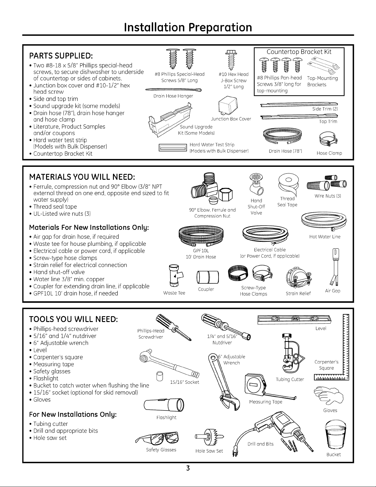
PARTS SUPPLIED:
• Two #8-18 x 5/8" Phillips special-head
screws, to secure dishwasher to underside
of countertop or sides of cabinets.
• Junction box cover and #10-1/2" hex
head screw
• Side and top trim
• Sound upgrade kit (some models)
• Drain hose (78"),drain hose hanger
and hose clamp
• Literature, Product Samples
and/or coupons
• Hard water test strip
(Models with Bulk Dispenser)
• Countertop Bracket Kit
#8 Phillips Special-Head #10 Hex Head
HI!iu'ml .....................................,H,u, ,U_
Drain Hose Hanger Q
MATERIALS YOU WILL NEED:
• Ferrule,compression nut and 90° Elbow (3/8" NPT
external thread on one end, opposite end sized to fit
water supply)
• Thread seal tape
• UL-Listed wire nuts (3)
Materials For New Installations Only:
• Air gap for drain hose, if required
• Waste tee for house plumbing, if applicable
• Electrical cable or power cord, if applicable
• Screw-type hose clamps
• Strain relief for electrical connection
• Hand shut-off valve
• Water line 3/8" min. copper
• Coupler for extending drain line, if applicable
• GPF10L10' drain hose, if needed
Screws 5/8" Long J-Box Screw
1/2" Long
Junction Box Cover
I[' ']1 Hard Water Test Strip
Waste Tee
(Models with Bulk Dispenser)
90° Elbow, Ferrule and
Compression Nut
GPFIOL
10'Drain Hose
Coupler Screw-Type
Countertop Bracket Kit
#8 Phillips Pan head Top Mounting
Screws5/8"longfor Brackets
top mounting
Drain Hose (78") Hose Clamp
Hand
Shut-Off Seal Tape
Valve
Electrical Cable
(or Power Cord, if applicable)
O
Hose Clamps
Strain Relief
SideTrim (2)
Top Trim
Wire Nuts (3)
Hot Water Line
1
Air Gap
TOOLS YOU WILL NEED:
• Phillips-head screwdriver
• 5/16" and 1/4" nutdriver
• 6" Adjustable wrench
• Level
• Carpenter's square
• Measuring tape
• Safety glasses
• Flashlight
• Bucket to catch water when flushing the line
• 15/16" socket (optional for skid removal)
• Gloves
For New Installations Only:
• Tubing cutter
• Drill and appropriate bits
• Hole saw set
?22w L
15/16" Socket
Safety Glasses
1/4" and
Nutdriver
Hole Saw Set
Tubing Cutter
MeasuringTape
Level
Carpenter's
Square
........... I
I ,hhhhl,hhhhhhl
%
Gloves
Bucket
Page 4
ADVANCE PLANNING
Installation Preparation
• These dishwashers are designed for versatility,
adaptable to virtually any installation.
• All models have a full-length door without
the traditional access panel.
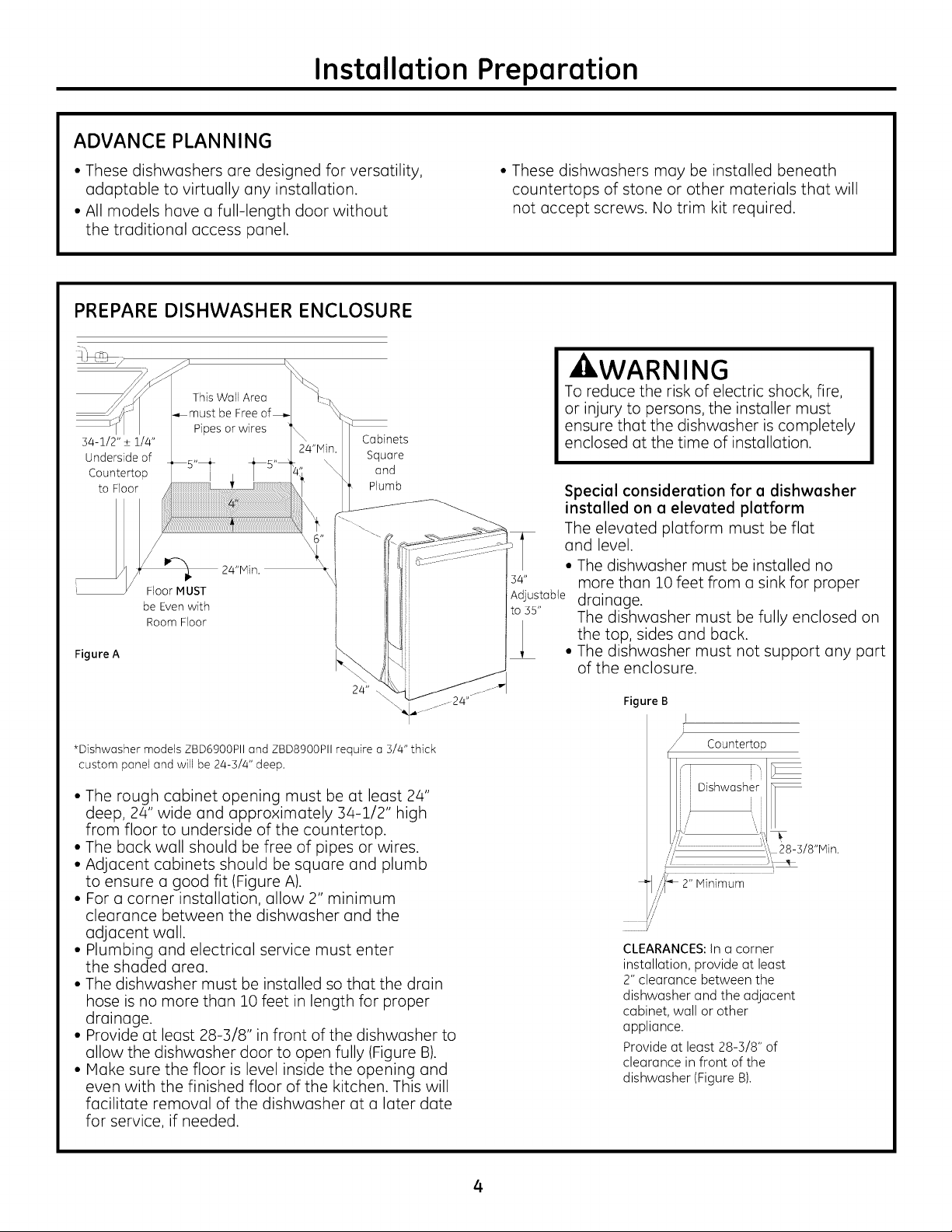
PREPARE DISHWASHER ENCLOSURE
This Wall Area
be Free
54-1/2" _+1//4"
Underside of
Countertop
to Floor
Figure A
/
,%
Floor MUST
be Even with
Room Floor
Pipes or wires
24"MJn.
Cabinets
Square
and
Plumb
• These dishwashers may be installed beneath
countertops of stone or other materials that will
not accept screws. No trim kit required.
kWARNING
To reduce the risk of electric shock, fire,
or injury to persons, the installer must
ensure that the dishwasher is completely
enclosed at the time of installation.
Special consideration for a dishwasher
installed on a elevated platform
The elevated platform must be flat
and level.
• The dishwasher must be installed no
s4" more than 10 feet from a sink for proper
Adjustable drainage.
toss" The dishwasher must be fully enclosed on
the top, sides and back.
• The dishwasher must not support any part
of the enclosure.
*Dishwasher models ZBD6900PII and ZBD8900PII require a 3/4" thick
custom panel and will be 24-3/4" deep.
• The rough cabinet opening must be at least 24"
deep, 24" wide and approximately 34-1/2" high
from floor to underside of the countertop.
• The back wall should be free of pipes or wires.
• Adjacent cabinets should be square and plumb
to ensure a good fit (Figure A).
• For a corner installation, allow 2" minimum
clearance between the dishwasher and the
adjacent wall.
• Plumbing and electrical service must enter
the shaded area.
• The dishwasher must be installed so that the drain
hose is no more than 10 feet in length for proper
drainage.
• Provide at least 28-3/8" in front of the dishwasher to
allow the dishwasher door to open fully (Figure B).
• IVlake sure the floor is level inside the opening and
even with the finished floor of the kitchen. This will
facilitate removal of the dishwasher at a later date
for service, if needed.
Figure B
I
Countertop
i
CLEARANCES:In a corner
installation, provide atleast
2" clearance between the
dishwasher and the adjacent
cabinet, wall or other
appliance.
Provide at least 28-3/8" of
clearance in front of the
dishwasher (Figure B).
4
Page 5
Installation Preparation
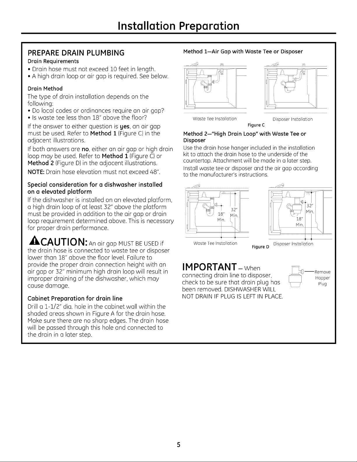
PREPARE DRAIN PLUMBING
Drain Requirements
• Drain hose must not exceed 10 feet in length.
• A high drain loop or air gap is required. See below.
Drain Method
The type of drain installation depends on the
following:
• Do local codes or ordinances require an air gap2
• Is waste tee less than 18" above the floor2
If the answer to either question is yes, an air gap
must be used. Refer to Method 1 (Figure C) in the
adjacent illustrations.
If both answers are no, either an air gap or high drain
loop may be used. Refer to Method 1 (Figure C)or
Method 2 (Figure D)in the adjacent illustrations.
NOTE: Drain hose elevation must not exceed 48".
Special consideration for a dishwasher installed
on a elevated platform
If the dishwasher is installed on an elevated platform,
a high drain loop of at least 32" above the platform
must be provided in addition to the air gap or drain
loop requirement determined above. This is necessary
for proper drain performance.
A,,-^, ,-,-,,,_,,,
_ll, k,,/_U/IUl_l: An airgap MUST BE USED if
the drain hose is connected to waste tee or disposer
lower than 18" above the floor level. Failure to
provide the proper drain connection height with an
air gap or 32" minimum high drain loop will result in
improper draining of the dishwasher, which may
cause damage.
Cabinet Preparation for drain line
Drill a 1-1/2" dia. hole in the cabinet wall within the
shaded ureas shown in Figure A for the drain hose.
Make sure there are no sharp edges. The drain hose
will be passed through this hole and connected to
the drain in a later step.
Method 1--Air Gap with Waste Tee or Disposer
Waste Tee Installation Disposer Installation
Figure C
Method 2--"High Drain Loop" with Waste Tee or
Disposer
Use the drain hose hanger included inthe installation
kit to attach the drain hose to the underside of the
countertop. Attachment will be made in a later step.
Install waste tee or disposer and the air gap according
to the manufacturer's instructions.
Waste Tee Installation
Figure D Disposer Installation
IMPORTANT- When
connectingdrainlineto disposer,
check tobe surethat drainplug has
been removed. DISHWASHER WILL
NOT DRAIN IFPLUG ISLEFT IN PLACE.
Page 6

Installation Preparation
PREPARE ELECTRICAL WIRING
FOR PERSONALSAFETY:Remove house fuse
or open circuit breaker before beginning
installation. Do not use an extension cord
WARNING
or adapter plug with this appliance.
Electrical Requirements
• Thisappliance must be supplied with 120V, 60 Hz. and
connected to an individual properly grounded branch
circuit, protected by a 15- or 20-ampere circuit breaker
or time-delay fuse.
• Wiring must be 2-wire with ground and rated for
75°C (176°F).
• Ifthe electrical supply does not meet the above
requirements, call a licensed electrician before
proceeding.
Grounding Instructions--Permanent Connection
This appliance must be connected to a grounded metal,
permanent wiring system, or an equipment-grounding
conductor must be run with the circuit conductors and be
connected to the equipment-grounding terminal or lead on
the appliance.
Grounding Instructions--Power Cord Models
This appliance must be grounded. In the event of a
malfunction or breakdown, grounding will reduce the risk
of electric shock by providing a path of least resistance
for electric current. This appliance is equipped with a
cord having an equipment-grounding conductor and
a grounding plug. The plug must be plugged into an
appropriate outlet that is installed and grounded in
accordance with all local codes and ordinances.
The improper connection of the equipment-
grounding conductor can result in a risk
of electric shock. Check with a qualified
WARNING
electrician or service representative if you
are in doubt that the appliance is properly
grounded.
Alternate
Receptacle
i
Figure E
For models equipped with power cord:Donot modify the
plug provided with the appliance; if it will not fit the outlet,
have u proper outlet installed by a qualified technician.
Cabinet Preparation and Wire Routing
• The wiring may enter the opening from either
side, rear or the floor within the shaded area
dimensioned in Figure A and illustrated above.
• Cut u 1-1/2" max. dia. hole to admit the electrical
cable. Cable direct connections may pass through
the same hole as the drain hose and hot water line,
if convenient. If cabinet wall is metal, the hole edge
must be covered with a bushing.
NOTE:Power cords with plug must pass through
a separate hole.
Electrical Connection to Dishwasher
Electrical connection is on the right front of dishwasher.
• For cable direct connections the cable must be routed
as shown in Figure E.Cable must extend a minimum
of 24" from the rear wall.
For power cord connections, install a 3-prong
grounding-type receptacle inthe sink cabinet
rear wall, 6" min. or 18" max. from the opening,
6" to 18" above the floor. The receptacle must be
accessible and therefore cannot be installed in
the back wall of the dishwasher enclosure.
i \
i
5" from
Cabinet
Page 7

Installation Instructions
PREPARE HOT WATER SUPPLY
Hot Water Line
• The line may enter from either side, rear or floor within
the shaded area shown in Figure F.
• The line may pass through the same hole as the
electrical cable and drain hose, or an additional
1-1/2" diameter hole may be cut to accommodate
the water line. If a power cord with plug isused, the
water line must not pass through the power cord hole.
Shut-off
Valve \
Hot i::::::::::
112.
From
Cabinet
Water Line Connection
• Turn off the water supply.
• Install a hand shut-off valve in an accessible location,
such as under the sink. (Optional, but strongly
recommended and may be required by local codes.)
• The water connection is on the bottom left side
of the dishwasher. Install the hot water inlet line, using
:3/8"or larger copper tubing. Routethe line as shown in
Figure Fand extend forward at least 19" from rear wall.
• Adjust the water heater to deliver water between 120°F
and 150°F.
• Flushwater line to clean out debris. Use a bucket to
catch water and debris.
• The hot water supply line pressure must be between
20 and 120 PSI.
l-l/
Oi(
Hal
X
_.r2222
19" From Wall
q_\_--2" From Floor
xCabinet Face Figure F
STEP 1 I LOCATE INSTALLATION ITEMS
• Locate the items in the installation package and set
aside for use in the listed steps.
• Trim pieces - Step 2
• Junction box cover - Step 7 or Step 19
• Drain hose and clamp- Step 10
• Countertop bracket kit - Step 12
• Screw kit - Step 16
• Drain hose hanger - Step 18
• Owner's Manual - Step 20 and Step 25
• Hard water test strip - Step 22
• Sound upgrade kit (selected models) - Step 2:3
• Product samples and/or coupons - Step 25
STEP 2 I INSTALL TRIM PIECES
In this step, you will need the trim pieces set aside
in Step 1.
• Presstop trim piece onto top of tub flange. Start with
the right edge and work your way to the left.
• Repeat process with the left and right trim pieces
working from the top down.
• Open and close the door to check that trim does not
bind and does not interfere with door latch or door
hinges.
Trim
Strip
CAUTION
The hot water supply line pressure must be at least
20 PSI.Lower pressures could cause the water valve
to leak and cause water damage.
'kCAUTION
Do not remove wood base until you are ready to install the
dishwasher. The dishwasher will tip over when the door is
opened if the wood base is removed.
Page 8

Installation Instructions
STEP 3 CHECK DOOR BALANCE
• With dishwasher on the wood skid,check the door
balance by opening and closing the door.
• Ifthe door dropswhen released,increasethe spring tension.
Ifthe door riseswhen released,decreasethe tension.
• Thereare two types of counter balance and therefore two
methods of adjustment. Identify which counter balance is
present and adjust tension accordingly. Pleasenote: if
there are 3 holeson the cable, usethe cable to adjust;
if there is onehole on cable usethe tub legto adjust.
Tgpe 1 - One-hole cable
Adjust tension by moving spring hook to one of the three
holes on the tub leg.
Figure H
One Hole
Tgpe 2 - Three-hole cable
Adjust tension by moving spring hook to one of the three
holes on the pulley cable.
STEP 4 I REMOVE WOOD BASE, INSTALL
LEVELING LEGS
IMPORTANT-Donot kick off wood base!
Damage will occur.
• Hovethedishw(]shercloseto theinst(]ll(]tionIoc(]tion(]ndI(]y
iton itsb(]ck.
• Removethefourlevelinglegsonthe undersideofthewoodb(]se
with(in (]djust(]blewrenchor15/16"socket.
• Disc(]rdb(]se.
/
Figure K
•Screwlevelinglegsb(]ckintothedishw(]sherfr(]me(]pproxim(]tely
1/8"fromfr(]me(isshown.
STEP 5 I REMOVE TOEKICK
• Removethe2toekick
screws(]ndtoekick.
Set(]sidefor use
inStep24.
\
Decrease
Figure I Increase Tension
Tension
After adjusting spring tension, open and close the door to
make sure the door operates smoothly. Ifthe door is hard
to move or if the spnng cable binds, check the routing of
the spring cable. The cable should be routed between the
shoulders of the pulley cable roller. Ifthe cable isoff the
roller: latch door, remove spring tension and route the
cable between the shoulders of the roller.See FigureJ.
Figure J _". ' _ "
Pulley
Correct Spring Incorrect Spring
Cable Routing Cable Routing
......... Toekick
........... Remove 2
Figure L
..... Toekick Screws
STEP 6 I REMOVE TOEKICK BRACE
Skipthisstep ifyour modeldoesnot havea soundupgradekit.
If your modeldoeshavea soundupgradekit, thisbrace must
beremoved.
• Removethe2toekick
br(]cescrews(]nd
toekickbr(]ce.
Disc(]rdbr(]ce
(]ndsetscrews
(]sideforusein
Step23.
Remove 2
Figure M
:: Toekick Screws
Page 9

Installation Instructions
STEP 7 INSTALL POWER CORD
Skipthisstepif dishwasherwill bepermanently connectedto
thehouseelectricalsystem.
Inthisstepyouwill needthejunctionboxcoverandthe #10x 1/2"
hexheadscrewfromthescrewkitsetasideinStep1.
ThepowercordandconnectionsmustcomplywiththeNational
ElectricalCode,Section422and/orlocalcodesandordinances.
Maximumpowercordlengthis6feet.PowerCordKitWX09×709Z0,
availablefor purchasefromanauthorizedGEApplianceDealer,
meetstheserequirements.
j Black
Figure N --_
• Installstrainreliefinjunctionboxbracket.
• Insertpowercordthroughstrainreliefandtighten.
• Makesureblack,whiteandgreendishwasherwiresarethreaded
throughsmallholeinjunction boxbracket.
• Connectlike-coloreddishwasherand powercordwires.Ifpower
cordwiresare notcolorcoded,connecttheribbedpowercord
wireto the whitedishwasherwire,the smoothpowercordwire
totheblackdishwasherwire andthegroundtothegreen
dishwasherwire.UseUL-listedwire nutsof appropriatesize.
• InstalljunctionboxcoversetasideinStepZ,using#10hexhead
screw.Besurewiresarenotpinchedunderthecover.
STEP 8 INSTALL 90 ° ELBOW
• Wrap90°elbowwiththreadsealtape.
• Installa 90°elbowontothewatervalve.
Front of Dishwasher
STEP 9 I POSITION WATER LINE AND
HOUSING WIRING
• Position water supply line and house wiring on the floor
of the enclosure to avoid interference with base of
dishwasher and components under dishwasher.
Figure P Wiring
Line
STEP 10 INSTALL DRAIN HOSE TO
DISHWASHER DRAIN PORT
In this step you will need the drain hose and clamp set
aside in Step 1.
• Stand the dishwasher upright.
• Place drain hose clamp over 1-3/16" inside diameter
end of drain hose with the clamp screw positioned
on the bottom of the hose.
IMPORTANT- Preventdrain hosedamage and
possible leaks. Becareful not to nick or cut the drain hose.
• Pushthe end of the drain hose over the drain pump
outlet being careful not to disturb the check valve.
Refer to Figure O.
• Seat the drain hose end against the hose stops on
the pump outlet.
• Position hose clamp against the front lip of the drain
hose and tighten clamp.
NOTE:Drain hose
supplied with
dishwasher is
approximately 78"
long. If a longer hose
is needed, a 120"
long hose (10 feet),
may be purchased
from an authorized
GEappliance dealer.
The 10' long hose is
part number GPFIOL
Pum Hose Stops
Outlet
90 ° EIbow_
Bracket
_Fill Hose
Thread SealTape
Figure O
• Do notovertighten90° elbow,watervalvebracketcouldbend
orwatervalvefitting couldbreak.
• Positionthe endoftheelbowtofacetherearofthedishwasher.
Tip for leak-free
connections:
• Insert hose against
stop on pump. Hose Clam
• Position clamp
against front lip of drain hose.
• Tighten clamp to at least 15 inch-pounds of torque.
Tip for quiet drain pump operation:
Position hose clamp with clamp screw on the bottom side
of the hose.Thiswill prevent the clamp from coming in
contact with the rear brace. Clamp contact with the rear
brace could create noise when the drain pump is running.
Page 10

Installation Instructions
STEP 11 INSERT DRAIN HOSE
THROUGH CABINET
• Positiondishwasher in front of cabinet opening. Insert
drain hose into the holein cabinet side. If a power cord is
used, guide the end through a separate hole.
Insulation
Blanket
Maximum
Drain Hose
Length 10'
iii Hose1_
"_ \ House Wiring
Figure R
TIP:Position water line and house wiring on the floor
to avoid interference with base of dishwasher.
STEP 12 I INSTALLCOUNTERTOPBRACKETS
• Determine if your countertop is granite or asimilar
material that will not accept screws. If so,skip this step
and go to step 1:3.
• Ifthe countertop iswood or a wood-like material, install
the countertop brackets set aside in step 1.
• Locate the inner set and outer set of mounting holes on
the back side of the dishwasher tub frame.
Buttons
Bracket Outer-Sel )f Holes
• Selectthe set of holes, inner-set or outer-set, that will
locate the countertop brackets away from the buttons
on the top of the dishwasher door.
• Fasten the 2 brackets to the back of the tub frame in
the selected positions using the #8 pan-head screws
included with the kit.
...............................................C°rrect/ I..........................
Power Cord (If Power Cord
(If Used) is NOT Used)
Figure S
STEP 12 INSTALLCOUNTERTOPBRACKETS
(c_nt)
IMPORTANT- The brockets con be mounted
in the inner-set or outer-set hole locations. You
must use the location that positions the brackets
over o non-button location on the top of the door.
Positioning the bracket over the push buttons will
cause damage to the push buttons.
I STEP 13 I SLIDE DISHWASHER THREE-
FOURTHS OF THE
WAY INTO CABINET
IMPORTANT- Do NOT PUSH AGAINST
FRONT PANEL WITH KNEE. DAMAGE WILL OCCUR.
• Grasp the dishwasher by its sides and slide it into
the opening a few inches at a time.
Figure U
_ Do not push against front door
panel with knee. Damage to
the door panel will occur.
• Asyou proceed, pull the drain hose through the opening
under the sink.Stop pushing when the front of the
dishwasher is a few inches forward of adjacent cabinets.
• Hake sure drain hose is not kinked under the
dishwasher and there is no interference with
the water line, wiring or any other component.
TIP:Hake sure the dishwasher will fit in the cabinet. Check
to be sure the power cable, drain hose, and hot water
line are not trapped behind the dishwasher. Utility lines
trapped behind the dishwasher prevent the dishwasher
from being pushed fully into the enclosure.
STEP 14 SLIDE DISHWASHER INTO
FINAL POSITION
Top of dishwasher door Bracket
Buttons -- G,::_._o
............................... Figure T
Do not install brackets over buttons or damage will occur
_" e2 UCleen _ Kese_ Jl .
• Pushthe dishwasher the rest of the way into
the cabinet.
• Pushthe sides with your hands. Do notpush the
dishwasher with your knee, as this will damage
the door.
• Check that the tub insulation blanket does not get
"bunched-up" or interfere with the springs as you
slide it into the cabinet.
• Center the dishwasher in the opening.
10
Page 11

Installation Instructions
STEP 14 SLIDE DISHWASHER INTO
FINAL POSITION (cont.)
• Front of door panel should beflush with face of cabinet.
• Carefully open and close the door to ensure that
the door panel does not catch or rub on the cabinet
frame. Refer to Figure V below.
• If the door catches or rubs on the frame, reposition and/
or level the unit (see Step 15) until the door moves freely
and does not contact the cabinet frame.
/
Correct
Alignment Door Catches on
Figure V
Cabinet Frame
Special Considerations for Positioning
Alignment
STEP 15 LEVEL DISHWASHER
IMPORTANT - Dishwashermustbelevelfor
proper dish rack operation and wash performance.
• Make sure 1/2" minimum gap is maintained.
• Place level on door
to check that the
dishwasher is level
side to side.
Remove lower
rack, place
level on lower UseLevel
rack track inside to Check
tub to check that Frontto
the dishwasher is Back
level front to back.
Figure Y
• Ifthe dishwasher is not level, adjust the four leveling
legs as illustrated in Figure Z.
• Ifadjustment to the right rear leveling leg is required,
access it by loosening the junction box bracket screw
(through the access hole) and rotate bracket clockwise.
Access Hole _ _..-_ Junction Box
S
Use Level
to Check
Side to
Side
i
The controls on these models are designed to be
hidden by your countertop. Align the dishwasher as
shown in Figure W. Leave a 1/2" minimum gap between
the underside of the countertop and the top of the
dishwasher door as shown in Figure X.
Use the leveling legs to increase or decrease the amount
of gap between the controls and the countertop.
IMPORTANT- Leave e 1/2" minimum
gap between the controls and the underside of the
countertop to prevent condensation end damage
to the control panel from screw heads.
Counterto
Figure W
Controls Hidden by
Countertop
Countertop
/
/
Min.
Dishwasher Door
1/2" l
Figure Z
• The dishwasher isproperly leveled when the level
indicator is centered left to right and front to back.
The dishwasher door should close without hitting
the sides of the tub.
• Replacethe lower rack when leveling is complete.
TIP:Avoid unnecessory service charges for poor wash
performonce end rock operation.
Pullthe dish racks halfway out. They should remain
stationary. Open and close the door. The door should fit
in the tub opening without hitting the side of the tub. If
the racks roll on their own, or the door hits the side of
the tub, relevel the dishwasher.
IM PORTANT- After leveling, verify thclt
the dishwasher is centered in the enclosure end the
door does not hit adjocent cabinets.
Figure X
11
Page 12

Installation Instructions
STEP 16 SECURE DISHWASHER TO
COUNTERTOP OR CABINET
In this step you will
need the 2 Phillips
special-head screws
set aside
in Step 1.
The dishwasher
must be secured to
the countertop or
the cabinet sides. When countertops are made of
wood, use Method 1. When countertops are granite
or other materials that will not accept screws, use
Method 2 to secure dishwasher at the sides.
Count ertop_--_""--->d_-_._
Mounting \, ./_'%/-_1
Brackets pj_
.u_ q/h iu_ IIII I Brackets
_rame_iHi IIIII _l
Figure AA
IMPORTANT- Avoid unnecessary
servicecharges.Drivescrews straightand flush.
Protrudingscrew heads willscratchthe top or
sidesofthe Brackets Wood Countertop
control panel /
and can
interfere with
door closing. Screws
Method 1-- FigureBB
Secure dishwasher to wood
countertop
• Fasten the dishwasher to the underside of the
countertop with 2 Phillips special-head screws
provided.
Method 2--Secure dishwasher with side-mounting
brackets
• Remove plug buttons (one on each side).
• Install screws through the dishwasher side mount
bracket and into the adjacent cabinet on each
side. Reinstall Stone Countertop Side Mounting Brackets
plug buttons.
Either Method--
Make certain
112" gap
minimum
is maintained. FigureCC
• When step is complete, close dishwasher door
and verify that gap between countertop and top
of dishwasher door is at least 1/2".
Screws
STEP 17 CONNECT WATER SUPPLY
Connect water supply line to 90° elbow.
• Slide compression nut, then ferrule over end of
water line.
• Insert water line into 90° elbow.
• Slide ferrule against elbow and secure with
compression nut.
IMPORTANT-check tobe surethat
door springdoes not rub orcontactthe fillhose
orwater supply line.Testby opening and closing
the door.Reroutethe linesifa rubbingnoiseor
interference occurs.
i
Figure EE
90 ° Elbow
Door Spring
Countertop
/
/
Dishwasher Door
12
Page 13

Installation Instructions
STEP 18 CONNECT DRAIN LINE
The molded end of the drain hose will fit 5/8" through
1" diameter inlet ports on the air gap, waste tee or
disposer.
• Determine size of inlet port.
• Cut drain hose connector on the marked line,
if required, to fit the inlet port.
Figure FF
j Cutting Line
IMPORTANT:Do not cut corrugc4ed
portion of hose
• If a longer drain hose is required, and you did not
purchase 10' long GPF10L drain hose, add up to
3-1/2' of length for a total of 10' to the factory
installed hose. Use 5/8" or 7/8" inside diameter
hose and a coupler to connect the two hose ends.
\
Hose Clamp
Coupler
Hose Clamp
DRAIN LINE INSTALLATION
• Connect drain line to air gap, waste tee or disposer
using the previously determined method.
• Secure the drain hose to the air gap, waste tee or
disposer with clamps.
Method 1--Air gap with waste tee or disposer
Insert the drain hose into the air gap as shown.
Waste Tee Installation Disposer Installation
Figure HH
Method 2--High Drain Loop with the Waste Tee
or Disposer
Route the drain hose of the dishwasher to a
minimum height of 32" from the floor with the
supplied hanger as shown.
Fasten to underside
of countertop
......-_¢!"
Fasten to underside
of countertop
f-S;')
Secure the connection with hose clamps.
NOTE: TOTAL DRAIN HOSE LENGTH MUST NOT EXCEED
10' FOR PROPER DRAIN OPERATION.
Waste Tee Installation
FigureII
Disposer Installation
IMPORTANT- One of the above methods
must be used ordishwasher willnotoperate
properly.
IMPORTANT- When
connectingdrainlineto disposer,
check to be surethatdrainplug
has been removed. DISHWASHER
WILL NOT DRAIN IFPLUG ISLEFT IN PLACE.
TIP: Avoid unnecessary service call charges. Always
be sure disposer drain plug has been removed before
attaching dishwasher drain hose to the disposer.
13
Page 14

Installation Instructions
STEP 19 CONNECT POWER SUPPLY
Skip this step if dishwasher is equipped with
power cord.
Verify that power is turned off at the source.
• Locate junction box cover set aside in Step 1.
• Secure house wiring to the back of the junction
box with a strain relief.
• Locate the three dishwasher wires, (white, black
and green) with stripped ends. Insert dishwasher
wires through the small hole in the junction box.
Connect like-colored dishwasher and power cable
wires using UL-listed wire nuts of appropiate size.
• Install the junction box cover. Check to be sure
that wires are not pinched under the cover.
STEP 20 PRETEST CHECK LIST
Review this list after installing your dishwasher
to avoid charges for a service call that is not
covered by your warranty.
Check to be sure power is OFF.
Open door and remove all foam and paper
packaging.
Locate the Owner's Manual set aside in Step 1.
Read the Owner's Manual for operating instructions.
Check door opening and closing. If door does not
open and close freely, check for proper routing of
spring cable over pulley. If door drops or closes
when released, adjust spring tension. See Step 3,
Figure J.
Check to be sure that wiring is secure under the
dishwasher, not pinched or in contact with door
springs or other components. See Step 9.
Check door alignment with tub. If door hits tub,
level dishwasher. See Step 15.
Pull lower rack out about halfway. Check to be
sure it does not roll back or forward on the door.
If the rack moves, adjust leveling legs. See Step 15.
WARNING
If house wiring is not 2-wire with
ground, a ground must be provided
by the installer. When house wiring
is aluminum, be sure to use UL-listed
anti-oxidant compound and
aluminum-to-copper connectors.
Check door alignment with cabinet. If door hits
cabinet, reposition or relevel dishwasher. See
Steps 14, 15 and 16.
Check that door spring does not contact water line,
fill hose, wiring or other components. See Step 17.
Verify water supply and drain lines are not kinked
or in contact with other components. Contact with
motor or dishwasher frame could cause noise.
See Steps 9 and lZ.
Turn on the sink hot water faucet and verify water
temperature. Incoming water temperature must
be between 120°F and 150°F. A minimum of 120°F
temperature is required for best wash performance.
See "Prepare Hot Water Line," page 7.
Add 2 quarts of water to the bottom of the
dishwasher to lubricate the pump seal.
Turn on water supply. Check for leaks. Tighten
connections if needed.
Remove protective film if present from the control
panel and door.
Avoid service call charges by ensuring there is
an air gap or drain hose routed through the
required 32" minimum height.
14
Page 15

Installation Instructions/Custom Panel Dimensions
STEP 21 DISHWASHER WET TEST
• Turnon power supply(orplug power cord into outlet,
ifequipped).
• Startthe unit to check for leaks.
- PushRINSEONLYbutton.
- PushSTART/RESETbutton one time.
- Closedoor.
• Checkto besurethat water enters the dishwasher. Ifwater
doesnot enter the dishwasher,check to besure the door
isclosed and latched. Make surethat water and power are
turned on.
• Checkfor leaksunder the dishwasher. Ifa leakisfound,
turn power off, then tighten connections. Restorepower after
leakiscorrected.
• Checkfor leaksaround the door.A leakaround the door
could be causedby door rubbing or hitting against
adjacent cabinetry. Repositionthe dishwasher if
necessary.SeeStep 14,15 and 16.
• Thedishwasher will drain and turn offabout 5 minutes after
itwas started. Check drain lines.If leaksare found,turn off
power supply and correct plumbing as necessary.Restore
power after corrections are made. SeeStep 10and 18.
• Opendishwasher door and make sure most of the water
hasdrained. If not, check that disposerplug has been
removed and/or air gap is clear.SeeStep 18. Alsocheck
drain lineto be sureit is not kinked.
• Runthe dishwasherthrough another "RinseOnly"cycle.
Checkfor leaksand correct if required.
STEP23 INSTALLSOUND UPGRADEKIT
IFEQUIPPED
Skipthis step if your model does not have the Sound
Upgrade Kit.
• Locatesound upgrade kit set aside inStep I and the two
screws set asidein Step6.
• Attach the plastic Sound Panelas shown in FigureKK
usingthe two screws.Thelower set of mounting holes
should be used.
• Besurethe sound panel is seatedin the notches on frame
asshown in Figure KK.
[ ]
under door panel.
STEP 22 SET WATER HARDNESS
Models with bulk dispenser only. Skip this step if your
dishwasher does not have the bulk dispense feature.
• Locate the hard water test strip setaside in Step1.
• Removestrip from package.
• Turnon the hot water and hold the strip under the stream,
following the directionson the package.
• Usethe value on the test stripto calibrate your dishwasher
for water hardness.Referto the sectiontitled "Water
HardnessCalibration"inyour Owner's Manual for
information on how to calibrateyour dishwasher.
Besure that the sound panel is seated
in the notch in the frame. (Both sides)
15
Figure KK
Page 16

STEP 24 INSTALL TOEKICK
• Locatetoekick and screws setaside in step 5.
Toekick
Attachment
Figure LL Screws
• Replacethe toekick and make sure it isagainst the floor.
• Insertand tighten the 2 toekick attachment screws.The
toekick should stay in contact with the floor to ensure quiet
dishwasher operation.
STEP 25 LITERATURE
• Besure to leavecomplete literature package, Installation
Instructions and product sampleswith the consumer.
NOTE: While performing installations described in this book,
safety glasses or goggles should be worn.
For Honogrom _ Iocol service in your oreo, coil
1.800.444.1845.
NOTE: Product improvement is a continuing endeavor at
General Electric. Therefore, materials, appearance and
specifications are subject to change without notice.
GE AppliGnces & Lighting
Appliances
General Electric Company
Louisville, KY/40225
GEApplionces.com
 Loading...