

Page 1

If you have questions, call 800.626.2000 or visit our website at: www.monogram.com
Monogram.
®
Installation
Instructions
Built-In Dishwashers
ZBD6800K
ZBD6880K
ZBD6890K*
Design Guide with
Installation Instructions
*For ZBD6890 Series also refer to the
instructions provided on the template
packed with that model.
Page 2

Safety Information
2
CONTENTS
Installation Preparation
Parts Supplied..............................................................................3
Materials You Will Need ............................................................3
Tools You Will Need ....................................................................3
Models Available ........................................................................4
Advance Planning ......................................................................4
Prepare Dishwasher Enclosure ................................................4
Drain Requirements ....................................................................5
Prepare Electrical Wiring ..........................................................6
Prepare Hot Water Line..............................................................7
Installation Instructions
Step 1, Check Door Balance......................................................7
Step 2, Remove Wood Base, Install Leveling Legs ..............8
Step 3, Remove ToeKick ............................................................8
Step 4, Install Power Cord ........................................................8
Step 5, Install 90° Elbow ............................................................8
Step 6, Position Water Line and House Wiring......................9
Step 7, Install Drain Hose, Guide Through Cabinet ..............9
Step 8, Slide Dishwasher Partially Into Cabinet ....................9
Step 9, Install Trim Pieces..........................................................9
Step 10, Position Dishwasher Under Countertop ................10
Step 11, Level Dishwasher ......................................................11
Step 12, Secure Dishwasher To Cabinet ..............................11
Step 13, Connect Water Supply ..............................................12
Step 14, Connect Drain Line ....................................................12
Step 15, Connect Power Supply..............................................13
Step 16, Pre-Test Check List....................................................13
Step 17, Dishwasher Wet Test ................................................14
Step 18, Replace Toekick ........................................................14
Step 19, Literature ....................................................................14
Custom Panel Dimensions
Custom Panel for Model ZBD6890..........................................15
BEFORE YOU BEGIN
Read these instructions completely and carefully.
•
IMPORTANT — Save these instructions for
local inspector’s use. Observe all governing codes and
ordinances.
•
Note to Installer
— Be sure to leave these
instructions with the Consumer.
•
Note to Consumer
— Keep these instructions
with your Owner’s Manual for future reference.
•
Skill Level
— Installation of this dishwasher requires
basic mechanical and electrical skills. Proper installation
is the responsibility of the installer. Product failure due
to improper installation is not covered under the GE
Appliance Warranty.
•
Completion Time — 1 to 3 Hours.
New installations require more time than replacement
installations.
•
IMPORTANT — The dishwasher MUST
be installed to allow for future removal from the
enclosure if service is required.
• If you received a damaged dishwasher, you should
immediately contact your dealer or builder.
READ CAREFULLY.
KEEP THESE INSTRUCTIONS.
FOR YOUR SAFETY
Read and observe all CAUTION and WARNINGS shown
throughout these instructions.
While performing installations described in this booklet,
gloves, safety glasses or goggles should be worn.
For Monogram local service in your area, 1.800.444.1845.
For Monogram service in Canada 1.888.880.3030
For Monogram Parts and Accessories, call 1.800.626.2002.
Page 3

TOOLS YOU WILL NEED:
Phillips head screwdriver
5/16" and 1/4" nutdriver
6" Adjustable wrench
Level
Carpenters square
Measuring tape
Safety glasses
Flashlight
Bucket to catch water when flushing the line
15/16" socket (optional for skid removal)
Gloves
For New Installations Only:
Tubing cutter
Drill and appropriate bits
Hole saw set
MATERIALS YOU WILL NEED:
Ferrule, compression nut and 90° Elbow (3/8" NPT
external thread on one end, opposite end sized to fit
water supply)
Thread seal tape
UL Listed wire nuts (3)
Materials For New Installations Only:
Air gap for drain hose, if required
Waste tee for house plumbing, if applicable
Electrical cable or power cord, if applicable
Screw type hose clamps
Strain relief for electrical connection
Hand shut-off valve
Water line 3/8" min. copper
Coupler for extending drain line, if applicable
PARTS SUPPLIED:
Two #8 Phillips flat head wood screws, 5/8" long to
secure dishwasher to underside of countertop or sides
of cabinetry. (Taped to top or side of dishwasher.)
Side and top trim pieces (on some models)
Template with mounting hardware (not shown)
for Model ZBD6890 Only
Drain Hose and Hose Clamp
Installation Preparation
3
Wire Nuts (3)
Hot Water line
Screw Type
Hose Clamps
Coupler
Hand
Shut-Off
Valve
2 Wood Screws
Hole Saw Set
Measuring Tape
Tubing Cutter
Drill and Bits
Phillips
Head
Screwdriver
15/16" Socket
1/4"
and 5/16"
Nutdriver
Safety Glasses
6" Adjustable
Wrench
Bucket
Flashlight
Gloves
Carpenters
Square
Level
Thread
Seal Tape
Air Gap
Strain Relief
Drain Hose
Hose Clamp
90° Elbow,
Ferrule and
Compression Nut
Electrical Cable
(or Power Cord, if applicable)
Waste Tee
Trim Pieces
(on some models)
Page 4

PREPARE DISHWASHER ENCLOSURE
• The rough cabinet opening must be at least 24" deep,
24" wide and approximately 34-1/2" high from floor to
underside of the countertop.
• Plumbing and electrical service must enter the shaded
area.
• The dishwasher must be installed so that drain hose is
no more than 10 feet in length for proper drainage.
WARNING
To reduce the risk of electric shock, fire, or
injury to persons, the installer must ensure
that the dishwasher is completely enclosed
at the time of installation.
ATTENTION
Pour réduire le risque de choc électrique,
d’incendie ou de blessures, l’installateur doit
s’assurer, au moment de l’installation, que le
lave-vaisselle est complètement enclos.
Clearance for Door
Opening 2" Minimum
Countertop
Dishwasher
28-3/8"
Figure B
Installation Preparation
CLEARANCES: When installed
into a corner, allow 2" min.
clearance between dishwasher
and adjacent cabinet, wall or
other appliances. Allow 28-3/8"
min. clearance from the front of
the dishwasher for door
opening (Figure B).
4
DISHWASHER MODELS
ZBD6880 SS, Stainless Steel
ZBD6800 BB, Black
ZBD6800 WW, White
ZBD6890 Requires a 3/4" custom panel and custom handle
ADVANCE PLANNING
• These dishwashers are designed for versatility,
adaptable to virtually any installation.
• All models have a full length door without the
traditional access panel.
• These dishwashers may be installed beneath
countertops of stone or other materials that will not
accept screws. No trim kit required.
* Dishwasher model
ZBD6890 requires a 3/4”
thick custom panel and will
be 24-3/4” deep
Figure A
This Wall Area
must be Free of
34-1/2"±1/4"
Underside of
Countertop
to Floor
Floor MUST
be Even with
Room Floor
Pipes or wires
5" 5"
4"
24" Min.
4"
24"
Min.
6"
Cabinets
Square
and
Plumb
34"
Adjustable
to 35"
*24"
24"
Page 5
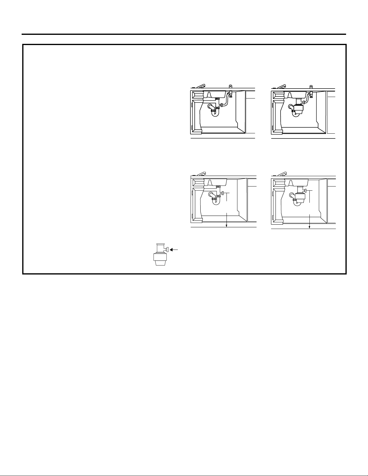
DRAIN REQUIREMENTS
• Follow local codes and ordinances.
• Do not exceed 10 feet distance to drain.
• Do not connect drain lines from other devices to the
dishwasher drain hose.
NOTE: This dishwasher is equipped with a high drain
loop. There is no minimum height required for drain hose
routing. However, 18" minimum from floor to center of
waste tee or disposer inlet is required. See Figure D.
DETERMINE DRAIN METHOD
The type of drain installation depends on the following
question.
Do local codes or ordinances require an air gap?
Is waste tee less than 18" above floor?
If the answer to either question is YES, Method 1 MUST
be used.
• If the answers are NO, either method may be used.
CABINET PREPARATION
• Drill a 1-1/2" dia. hole in the cabinet wall within the
shaded areas shown in Figure A for the drain hose
connection. The hole should be smooth with no
sharp edges.
Method 1—Air Gap with Waste Tee or Disposer
An air gap must be used when required by local codes and
ordinances. The air gap must be installed according to
manufacturers instructions.
Method 2—Built-in “High Drain Loop” with
Waste Tee or Disposer
Figure C
Figure D
18"
Min.
18"
Min.
IMPORTANT
—
When connecting
drain line to disposer, check to be sure that
drain plug has been removed. DISHWASHER
WILL NOT DRAIN IF PLUG IS LEFT IN PLACE.
5
Installation Preparation
Remove
Hopper
Plug
Page 6

6
Installation Preparation
PREPARE ELECTRICAL WIRING
WARNING
FOR PERSONAL SAFETY: Remove house
fuse or open circuit breaker before
beginning installation. Do not use an
extension cord or adapter plug with this
appliance.
ATTENTION
SÉCURITÉ : Enlever le fusible du circuit
ou déclencher le disjoncteur avant de
commencer l’installation. Avec cet
appareil, ne pas utiliser une rallonge ou
un adaptateur de prise.
Electrical Requirements
• This appliance must be supplied with 120V, 60 Hz., and
connected to an individual properly grounded branch
circuit, protected by a 15 or 20 ampere circuit breaker
or time delay fuse.
• Wiring must be 2-wire with ground and rated for
75°C (176°F).
• If the electrical supply does not meet the above
requirements, call a licensed electrician before
proceeding.
Grounding Instructions—Cable Direct
This appliance must be connected to a grounded metal,
permanent wiring system, or an equipment grounding
conductor must be run with the circuit conductors and
be connected to the equipment grounding terminal or
lead on the appliance.
Grounding Instructions—Power Cord Models
This appliance must be grounded. In the event of a
malfunction or breakdown, grounding will reduce the
risk of electric shock by providing a path of least
resistance for electric current. This appliance is
equipped with a cord having an equipment grounding
conductor and a grounding plug. The plug must be
plugged into an appropriate outlet that is installed and
grounded in accordance with all local codes and
ordinances.
WARNING
The improper connection of the equipment
grounding conductor can result in a risk
of electric shock. Check with a qualified
electrician or service representative if you
are in doubt that the appliance is properly
grounded.
ATTENTION
Le mauvais branchement du conducteur
de mise à la terre peut causer des risques
de choc électrique. En cas de doute sur
la mise à la terre de l’appareil, consulter
un électricien agrée ou un technicien de
réparation.
For models equipped with power cord: Do not modify
the plug provided with the appliance; if it will not fit the
outlet, have a proper outlet installed by a qualified
technician.
Cabinet Preparation and Wire Routing
• The wiring may enter the opening from either side,
rear or the floor within the shaded area.
• Cut a 1-1/2" max. dia. hole to admit the electrical
cable. Cable direct connections may pass through
the same hole as the drain hose and hot water line,
if convenient. If cabinet wall is metal, the hole edge
must be covered with a bushing.
• NOTE: Power cords with plug must pass through a
separate hole.
Electrical Connection to Dishwasher
Electrical connection is on the right front of
dishwasher.
• For cable direct connections the cable must be
routed as shown in Figure E. Cable must extend
a minimum of 24" from the rear wall.
• For power cord connections, install a 3-prong
grounding type receptacle in the sink cabinet rear
wall, 6" min. or 18" max. from the opening, 6" to 18"
above the floor.
Figure E
Alternate
Receptacle
Location
18"
18"
6"
6"
1-1/2" Dia.
Hole (Max.)
Receptacle
Location
Area
24"
from Wall
Ground
Black
3"
from
Cabinet
White
Page 7

PREPARE HOT WATER LINE
• The line may enter from either side, rear or floor
within the shaded area shown in Figure F.
• The line may pass through the same hole as the
electrical cable and drain hose. Or, cut an additional
1-1/2" dia. hole to accommodate the water line.
If power cord with plug is used, water line must not
pass through power cord hole.
Water Line Connection
• Turn off the water supply.
• Install a hand shut-off valve in an accessible location,
such as under the sink. (Optional, but strongly
recommended and may be required by local codes.)
• Water connection is on the left side of the dishwasher.
Install the hot water inlet line, using no less than 3/8"
O.D. copper tubing. Route the line as shown in Figure F
and extend forward at least 19" from rear wall.
• Adjust water heater for 120°F to 150°F temperature.
• Flush water line to clean out debris.
• The hot water supply line pressure must be 20-120 PSI.
Installation Instructions
7
CAUTION
Do not remove wood base until you are ready
to install the dishwasher. The dishwasher will tip over
when the door is opened if the wood base is removed.
PRUDENCE
Il ne faut pas enlever la base de bois avant
d’être prêt à installer le lave-vaisselle. Quand la base de
bois est enlevée et la porte ouverte, le lave-vaisselle
bascule.
BEFORE YOU BEGIN
Locate and set aside the two Phillips head
mounting screws wrapped with yellow tape
and stuck to the top or side of the dishwasher.
Figure F
CHECK DOOR BALANCE
• With dishwasher on the wood skid, check the door
balance by opening and closing the door.
• If the door drops when released, increase the spring
tension. If the door rises when released, decrease
the tension.
NOTE: The addition of the custom panel on model
ZBD6890 will require exchange of the factory installed
springs. Use the heavy-duty springs provided. See the
custom panel template for additional instructions.
• Position the spring for increased or decreased
tension as required.
NOTE: Adjust both balance springs to the same
amount of tension to prevent excessive door
twisting during use.
TIP: If door does not open easily or falls too quickly,
check the spring cable routing. Check that the cable
is properly aligned on the pulley (as shown).
STEP 1
Figure G
Valve
2"
1-1/2" Dia.
Hole
19" From Wall
2" From Floor
Shut-off
Hot
From
Cabinet
Cabinet Face
Pulley
Use This
Mounting
Hole
Shoulder
Correct Spring
Cable Routing
Increase
Tension
Decrease
Tension
Page 8

REMOVE WOOD BASE,
INSTALL LEVELING LEGS
IMPORTANT — Do not kick off wood base!
Damage will occur.
• Move the dishwasher close to the installation location
and lay it on its back.
• Remove the four leveling legs on the underside of
the wood base with an adjustable wrench or 15/16"
socket.
• Discard base.
• Screw leveling legs back into the dishwasher frame,
approximately 1/4" from frame as shown.
STEP 2
REMOVE TOEKICK
• Remove the two toekick screws.
STEP 3
8
T
oekick
Remove 2
Toekick Screws
Installation Instructions
Figure H
Approx.
1/4"
Figure J
INSTALL POWER CORD
Skip this step if dishwasher will be direct wired or
has a factory installed power cord.
The power cord and connections must comply with
the National Electrical Code, Section 422 and/or local
codes and ordinances.
• Maximum power cord length is 4 feet beyond the
back of the dishwasher.
• Connect incoming power cord white (or ribbed) to
dishwasher white, black (or smooth) to black and
ground to dishwasher green wire. Use UL listed wire
nuts of appropriate size.
• Replace junction box cover. Be sure wires are not
pinched under the cover.
STEP 4
Figure K
INSTALL 90° ELBOW
• Wrap 90° elbow with thread seal tape.
• Install a 90° elbow onto the water valve.
• Do not overtighten 90° elbow, water valve bracket
could bend or water valve fitting could break.
• Position the end of the elbow to face the rear of the
dishwasher.
STEP 5
Figure L
Remove
Junction Box
Cover
C
Check That White, Black and
Green Dishwasher Wires Are Threaded
Thru Small Hole in Bracket
A
B
Insert Power
Cord Wires Thru
Strain Relief
and Tighten
Ground
Use UL Listed
Wire Nuts
White
D
Black
Front of Dishwasher
Water Valve
Bracket
90°
Elbow
Fill
Hose
Thread
Seal Tape
Page 9

Drain
Outlet
Hose
Clamp
Shoulder
Stop
INSTALL TRIM PIECES
Skip this step if trim is not supplied with the
dishwasher.
• Locate trim strips inside dishwasher.
• Press trim onto the tub flange on each side. Start
with the top edge, pressing on as you move towards
the bottom.
• Press the two top trim pieces on each side of
the latch.
• Open and close the door to check that trim does not
bind and does not interfere with door latch.
STEP 9
POSITION WATER LINE
AND HOUSING WIRING
• Position water supply line and house wiring on the
floor of the opening to avoid interference with base
of dishwasher and components under dishwasher.
STEP 6
9
Figure Q
Trim Strip
Trim
Strip
Trim
Strip
Water
Line
House
Wiring
5"
5"
4"
6"
4"
Installation Instructions
Figure M
SLIDE DISHWASHER
PARTIALLY INTO CABINET
DO NOT PUSH AGAINST FRONT PANEL WITH KNEES.
DAMAGE WILL OCCUR.
• Slide dishwasher into the opening a few inches
at a time.
• As you proceed, pull the drain hose through the
opening under the sink. Stop pushing when the
dishwasher is a few inches forward of adjacent
cabinetry.
• Make sure drain hose is not kinked under the
dishwasher and there is no interference with the
water line and wiring or any other component.
STEP 8
Figure P
INSTALL DRAIN HOSE,
GUIDE THROUGH CABINET
• Remove tape and wire tie holding the clamp to the
drain hose. Be careful not to damage the drain hose.
• Stand the dishwasher upright.
• Slip the supplied hose
clamp over the small
end of the hose.
Do not tighten.
• Push hose over the drain outlet on the back side of
the dishwasher. See illustration. Push the hose over
the outlet and against the shoulder stop.
• Tighten the hose clamp with a 1/4" nut driver.
• Position the dishwasher in front of the opening.
Insert drain hose into the cabinet side. If power cord
is used, guide the end through a separate hole.
STEP 7
Figure N
Figure O
Reposition Dishwasher
by Grasping Both
Do Not Push Against
Front Door Panel With
Knee. Damage to The
Door Panel Will Occur.
Sides With Hands
Insulation
Blanket
Power Cord
Water
Line
Drain
Hose
(If Used)
House
Wiring
Page 10

POSITION DISHWASHER UNDER COUNTERTOP
STEP 10
10
• Push the dishwasher into the cabinet.
• Push at the sides with your hands. Do not use your
knee against the door since door damage will occur.
• Check that the tub insulation blanket does not get
“bunched-up” or interfere with the springs as you
slide it into the cabinet.
• Center the dishwasher in the opening.
• Check that the edges of the dishwasher door are
behind the cabinet frame and aligned with the front
face of the cabinet as shown.
• Carefully open and close the door to ensure that the
door panel does not catch or rub on the cabinet frame.
• If the door catches or rubs on the frame, reposition
and/or level the unit (see Step 11) until the door moves
freely and does not contact the cabinet frame.
The controls are designed to be hidden by your
countertop. Align the dishwasher as shown in Figure T.
TIP: For best appearance installations of the ZBD6890
models, it may be necessary to cut off the back panel
of the tub insulation blanket so that the dishwasher
door panel can be aligned flush with the kitchen
cabinet panels.
NOTE: If the drain hose gets trapped between the wall
and the back side of the dishwasher, it can prevent the
dishwasher from sliding all the way back into the
cabinet opening, and thus preventing a flush fit with
the kitchen cabinet panels.
NOTE: If this dishwasher is replacing an existing
dishwasher, the old counter top bracket screw holes
may not be in the correct position to accept a top
control model. New holes may be required.
TIP: The leveling legs can be used to increase or
decrease the amount of gap between the controls and
the countertop affecting the visibility of the controls.
IMPORTANT — Leave enough gap between
the controls and the countertop brackets so that the
screwheads do not contact and scratch the controls.
Control Panel
Countertop
Gap for Clearance
to Mounting Screws
Approx. 3/8" + 1/8"
Countertop
Figure U
Figure V
Top View
Controls Hidden
by Countertop
Installation Instructions
Figure S
Figure T
Figure R
Do Not Push Against
Front Door Panel With
Knee. Damage to The
Door Panel Will Occur.
Door
Fits and
Swings
Back
Behind
Cabinet
Frame
Correct
Alignment
Reposition Dishwasher
by Grasping Both
Sides With Hands
Door Catches
on Cabinet Frame
Incorrect
Alignment
Page 11

LEVEL DISHWASHER
IMPORTANT — Dishwasher must be level
for proper dish rack operation and wash performance.
• Place level on door
and rack track inside
the tub as shown to
check that the
dishwasher is level.
• Level the
dishwasher by
adjusting the
four leveling legs
individually.
• If adjustment to the
right rear leveling
leg is required, gain
access by loosening
junction box bracket screw (through the access hole)
and rotate bracket clockwise.
TIP: Pull lower rack out, about halfway. Check to
be sure the rack does not roll forward or back into
dishwasher. If the rack rolls in either direction, the
dishwasher must be leveled again.
• If the door hits the tub, the dishwasher is not installed
correctly. Adjust leveling legs to align door to tub.
STEP 11
11
Installation Instructions
Figure W
Figure X
SECURE DISHWASHER TO CABINET
STEP 12
The dishwasher must be secured to the countertop or
the cabinet sides. When countertops are made of wood,
use Method 1. When countertops are granite or other
materials that will not accept screws, use Method 2 to
secure dishwasher at the sides.
IMPORTANT — After leveling, verify that
the dishwasher is still in the correct position shown in
Step 10.
IMPORTANT — Drive screws straight and
flush. Protruding screw heads will scratch the top or
sides of the control panel and can interfere with door
closing.
Method 1—Secure dishwasher to wood
countertop
• Fasten the dishwasher to the underside of the
countertop with 2 Phillips screws provided.
Method 2—Secure dishwasher with side
mounting brackets
• Remove plug buttons (one on each side).
• Install screw through the hole in the side of the
dishwasher and into the adjacent cabinet.
Reinstall plug buttons.
Figure Y
Figure AA
Figure Z
Check
Level
Front
to Back
Check
Level
Side
To Side
Brackets
Access Hole
Turn Legs
to Adjust
Wood Countertop
Side Mounting
Brackets
Countertop
Mounting
Tub
Frame
Brackets
Stone Countertop
Side Mounting Brackets
Plug Buttons
Screws
Page 12

CONNECT DRAIN LINE
FOLLOW ALL LOCAL CODES AND ORDINANCES.
The drain hose molded end will fit 5/8" or 1" diameter
connections on the air gap, waste tee or disposer. Cut
on the marked line as required for your installation.
• If a longer drain hose is required, add up to 42" of
length for a total of 10 ft. to the factory installed hose.
Use 5/8" or 7/8" inside diameter hose and a coupler to
connect the two hose ends. Secure the connection
with hose clamps.
• Secure the drain hose to the air gap, waste tee or
disposer with clamps.
NOTE: TOTAL DRAIN HOSE LENGTH MUST NOT EXCEED
10 FEET FOR PROPER DRAIN OPERATION.
DRAIN LINE INSTALLATION
• Connect drain line to air gap, waste tee or disposer
using either previously determined method.
Method 1—Air gap with waste tee or disposer
Method 2—Built-in “High drain loop” with
waste tee or disposer
IMPORTANT — When
connecting drain line to disposer,
check to be sure that drain plug has
been removed. DISHWASHER WILL
NOT DRAIN IF PLUG IS LEFT IN PLACE.
TIP: Avoid unnecessary service call charges. Always
be sure disposer drain plug has been removed before
attaching dishwasher drain hose to the disposer.
STEP 14
CONNECT WATER SUPPLY
Connect water supply line to 90° elbow.
• Slide compression nut, then ferrule over end of
water line.
• Insert water line into 90° elbow.
• Slide ferrule against elbow and secure with
compression nut.
IMPORTANT
—
Check to be sure that door
spring does not rub or contact the fill hose or water supply
line. Test by opening and closing the door. Re-route the
lines if a rubbing noise or interference occurs.
STEP 13
12
90° Elbow
Ferrule
90° Elbow
Compression Nut
Door Spring
Hot Water
Supply Line
Installation Instructions
Figure BB
Figure CC
Figure DD
Figure EE
Waste Tee Installation Disposer Installation
Figure FF
18"
Min.
18"
Min.
Disposer Installation
Waste Tee Installation
Remove
Hopper
Plug
Cutting Line
1"
5/8"
IMPORTANT: Do not cut corrugated
portion of hose
Coupler
Hose Clamp
Hose Clamp
Page 13

13
Installation Instructions
PRE-TEST CHECK LIST
Review this list after installing your dishwasher to
avoid charges for a service call that is not covered
by your warranty.
Check to be sure power is OFF.
Open door and remove all foam and paper
packaging.
Locate the Owner’s Manual in the literature
package.
Read the Owner’s Manual for operating instructions.
Check door opening and closing. If door does not
open and close freely or tends to fall, check spring
cable routing and spring adjustments. See Step 1.
Check to be sure that wiring is secure under the
dishwasher, not pinched or in contact with door
springs or other components. See Steps 8 and 10.
Check door alignment with tub. If door hits tub,
level dishwasher. See Step 11.
Pull lower rack out, about half way. Check to be
sure it does not roll back or forward on the door.
If the rack moves, adjust leveling legs. See Step 11.
Check door alignment with cabinet. If door hits
cabinet, reposition or relevel dishwasher. See
Steps 10, 11 and 12.
Check that door spring does not contact water line,
fill hose, wiring or other components. See Step 13.
Verify water supply and drain lines are not kinked
or in contact with other components. Contact with
motor or dishwasher frame could cause noise.
See Steps 6 and 8.
Turn on the sink hot water faucet and verify water
temperature. Incoming water temperature must
be between 120°F and 150°F. A minimum of 120°F
temperature is required for best wash performance.
See “Prepare Hot Water Line,” page 7.
Add 2 quarts of water to the bottom of the
dishwasher to lubricate the pump seal.
Turn on water supply. Check for leaks. Tighten
connections if needed.
Remove protective film if present from the control
panel and door.
STEP 16
CONNECT POWER SUPPLY
Skip this step if equipped with power cord.
Go to step 16.
Verify that power is turned off at the source.
• Remove junction box cover “A”.
• Secure house wiring to the back of the junction box
with a strain relief “B”.
• Locate the three dishwasher wires, (white, black
and green) with stripped ends. Insert dishwasher
wires through the small hole in the junction box “C”.
Use wire nuts to connect incoming ground to green,
white to white and black to black “D”.
• Replace junction box cover “E”. Check to be sure
that wires are not pinched under the cover.
WARNING
If house wiring is not 2-wire with ground,
a ground must be provided by the
installer. When house wiring is aluminum,
be sure to use UL Listed anti-oxidant
compound and aluminum-to-copper
connectors.
ATTENTION
Si le circuit de la maison n’est pas un
circuit à deux fils plus fil de terre,
l’installateur doit installer un fil de terre.
Quand le circuit de la maison est en
aluminium, il faut prendre soin d’utiliser
une pâte antioxydante et des connecteurs aluminium
à cuivre sur la liste UL.
STEP 15
Figure GG
A
Remove
Junction Box
Cover
Check That White, Black and
C
Green Dishwasher Wires Are Threaded
Thru Small Hole in Bracket
B
Insert Power
Cord Wires Thru
Strain Relief
and Tighten
Ground
Replace Junction Box Cover
E
White
D
Use UL Listed
Wire Nuts
Black
Page 14

REPLACE TOEKICK
• Place toekick against the legs of the dishwasher.
• Align the toekick with the bottom edge and make sure
it is against the floor.
• Insert and tighten the two toekick attachment screws.
The toekick should stay in contact with the floor.
TIP: Make sure toekick is against floor to minimize
noise.
STEP 18
14
Installation Instructions
LITERATURE
• Be sure to leave complete literature package and
installation instructions with the consumer.
STEP 19
Figure HH
DISHWASHER WET TEST
Turn on power supply (or plug power cord into
outlet, if equipped).
Start the unit to check for leaks.
– Push RINSE ONLY pad.
– Push START/RESET pad one time.
– Close door.
Check to be sure that water enters the dishwasher.
If water does not enter the dishwasher, check to
be sure that water and power are turned on.
Check for leaks under the dishwasher. If a leak
is found, turn power supply off, then tighten
connections. Restore power after leak is corrected.
Check for leaks around the door. A leak around the
door could be caused by door rubbing or hitting
against adjacent cabinetry. Reposition the
dishwasher if necessary. See Step 12.
The dishwasher will drain and turn off about
5 minutes after it was started. Check drain lines.
If leaks are found, turn power off at the breaker
and correct plumbing as necessary. Restore power
after corrections are made. See Step 14.
Open dishwasher door and make sure most of the
water has drained. If not, check that disposer plug
has been removed and/or air gap is not plugged.
See Step 14. Also check drain line for kinking.
Run the dishwasher through another “Rinse Only”
cycle. Check for leaks and correct if required.
STEP 17
Toekick
Attachment Screws
Page 15

Custom Panel Dimensions
15
CUSTOM PANEL FOR MODEL ZBD6890
This dishwasher requires a field installed 3/4" thick
custom panel and custom handle. An installation
template is packed with these models and may be
obtained in advance. Order Pub. No. 31-30569.
Complete panel installation instructions are included
on the template.
STEP A—Determine custom panel height
1. Measure dimension A, from the underside of the
countertop to the bottom of adjacent cabinets.
2. Subtract 1/4". This allows a 1/4" clearance gap
between the underside of the countertop and the
top of the dishwasher door.
HEIGHT = A – 1/4"
NOTE: 30-1/16" minimum panel height is required to
cover the door frame. Panel height varies depending
on installation. Consideration must be given to door
swing clearance above the toekick.
STEP B—Determine custom panel width
1. Measure dimension B, the rough opening width.
2. Subtract 1/4" for clearance (1/8" on each side).
WIDTH = B – 1/4"
NOTE: The most common panel dimensions are
30-1/4"H and 23-3/4"W.
IMPORTANT: To ensure optimum door balance
performance, it is recommended that the door
panel weight be no more than 14 lbs.
Figure II
A
Floor
Custom
Panel Size
B
3/4" Max.
Countertop
Cabinets
Side
View
Bottom of
Adjacent Cabinetry
Page 16

Pub. No. 31-30568
Part No. 206C1559P108
12-03 JR
NOTE: While performing installations described in this book,
safety glasses or goggles should be worn.
For Monogram®local service in your area, call
1.800.444.1845.
NOTE: Product improvement is a continuing endeavor at
General Electric. Therefore, materials, appearance and
specifications are subject to change without notice.
GE Consumer Products
General Electric Company
Louisville, KY 40225
© 2003 General Electric Company
Monogram.
®
 Loading...