

Page 1
Installation
Instructions
Built-In Dishwashers
ZBD1800G
Monogram:_
Page 2
Safety Information
BEFORE YOU BEGIN
Read these instructions completely and carefully.
•IMPORTANT- Savetheseinstructions
for local inspector's use. Observe all governing
codes and ordinances.
• Note to Installer -- Be sure to leave these
instructions with the Consumer.
• Note to Consumer -- Keep these instructions
with your Owner's Manual for future reference.
° Skill Level -- Installation of this dishwasher
requires basic mechanical and electrical skills.
Proper installation is the responsibility of the
installer. Product failure due to improper installation
is not covered underthe GEAppliance Warranty.
• Completion "13me -- 1 to 3 Hours.
New installations require more time than
replacement installations.
CONTENTS
Installation Preparation
Parts Supplied ....................................................................3
Materials You Will Need ..................................................3
Tools You Will Need ..........................................................3
Prepare Dishwasher Enclosure ......................................4
Drain Requirements ..........................................................5
Prepare Electrical Wiring ................................................6
Prepare Hot Water Line....................................................7
Installation Instructions
Step 1, Check Door Balance ............................................8
Step 1A,Adjust Door Springs ..........................................8
Step 2, Adjust Leveling Legs ............................................9
Step 3, Remove ToeKick ..................................................9
Step 4, Install Power Cord ................................................9
• IMPORTANT --The dishwasher MUST
be installed to allow for future removal from the
enclosure if service is required.
If you received a damaged dishwasher, you should
immediately contact your dealer or builder.
READ CAREFULLY.
KEEP THESE INSTRUCTIONS.
FOR YOUR SAFETY
Read and observe all CAUTION andWARNINGS shown
throughoutthese instructions.
While performinginstallations described in this booklet,
gloves,safetyglasses or goggles shouldbe worn.
ForMonogram local service in your area, 1.800.444.1845.
ForMonogram service in Canada 1.888.880.3030
ForMonogram Parts and Accessories, call 1.800.626.2002.
Step
5, Install 90° Elbow ..................................................9
Step
6, Position Water Line and House Wiring ..........10
Step
7, Install Drain Hose Through Cabinet ................10
Step
8, Slide Dishwasher Partially Into Cabinet ........10
Step
9, Position Dishwasher Under Countertop ........11
Step
10,Level Dishwasher ............................................11
Step
11,Secure Dishwasher To Cabinet ....................12
Step
12,Connect Water Supply ....................................12
Step
13,Connect Drain Line ..........................................13
Step
14,Connect Power Supply ....................................14
Step
15, Pre-Test Checklist ............................................14
Step
16,Dishwasher Wet Test ......................................15
Step
17,Replace Toekick ................................................15
Step
18,Literature ............................................................15
2
Page 3

Installation Preparation
PARTS SUPPLIED:
[] Two #8Phillipsflat head wood screws, 5/8"long
to secure dishwasher to underside of countertop
(in literature package).
[] Two Phillips head, color matched toekick screws
(in literature package).
MATERIALS YOU WILL NEED:
[] Ferrule, compression nut and90° Elbow (3/8"NPTexternal
thread on one end, opposite end sizedto fit water supply)
[] Thread seal tape
[] ULListed wire nuts (3)
Materials For New Installations Only:
[] Air gap for drain hose, if required
[] Waste tee for house plumbing, if applicable
[] Electrical cable or power cord, if applicable
[] Screwtype hose clamps
[] Strain relief for electrical connection
[] Handshut-off valve
[] Water line 3/8"min. copper
[] Couplerfor extendingdrain line, if applicable
2 Wood Screws
90° Elbow, Valve
Ferruleand
CompressionNut
Waste Tee
F_q
Air 6ap
Shut-Off
Electrical Cable
(or Power Cord,if applicable)
ScrewType StrainRelief
Hose Clamps
2 Color Matched
Toekick Screws
Wire Nuts (3)
Thread
Seal Tape
HotWater line
Coupler
[] Phillips head screwdriver P
TOOLS YOU WILL NEED: _ _ Level
[] 5/16"and 1/4"nutdriver Head
[] 6"Adjustable wrench Screwdriver Nutdriver
[] Carpenterssquare table Square
[]Measuring tape _ I:,:,:i:,:,:i:,:i:,:i:,',,
[] Safety glasses Flashlight
[]Level ,'_ __ _ Carpenters
[] Flashlight TubingCutter
[][] 61ovesBUCketto catch water when flushing the line __ -_
Measuring Tape
For New Installations Only: Safety Blasses
[] Tubingcutter Bucket
[][] HoleDrillandsawappropriatesetbits _
6loves HoleSawSet
3
Page 4

Installation Preparation
PREPARE DISHWASHER ENCLOSURE
34"to35"
Undersided
Countertop
toFloor
FloorMUST
beEvenwith
RoomFloor
FigureA
• The rough cabinet opening must be at least 24" deep
and 17-5/8"to 18"wide. The opening should be 34"
to 35" max. height.
• Plumbing and electrical service must enter the
shaded area.
• The dishwasher must be installed so that drain hose
is no more than 10feet in length for proper drainage.
• The dishwasher must be fully enclosed on the top,
sides and back, and must not support any part of
the enclosure.
• These dishwashers may be installed beneath
countertops of stone or other materials that
will not accept screws. No trim kit required.
}abinets
Square
and
Plumb
324/2"
Adjustable
to35"
`&WARNING
To reduce the risk of electric shock, fire, or injury
to persons, the installer must ensure that the
dishwasher is completely enclosed at the time
of installation.
,&ATTENTION
Pour r_duire le risque de choc _lectrique,
d'incendie ou de blessures, I'installateur dolt
s'assurer, au moment de I'installation, que le
lave-vaisselle est compl_tement enclos.
CLEARANCES:When
installed into acorner,
allow 2"rain. clearance
between dishwasher and
adjacent cabinet, wall or
other appliances. Allow
25-5/8"min. clearance
from the front of the
dishwasher for door
opening. Figure B
NOTE: ADA installation, (32-1/2") beneath 34" high
countertops may be accomplished by adjusting the
toekick and leveling legs.
Counter[op
ClearanceforDoor
Opening2"Minimum
FigureB
Page 5
Installation Preparation
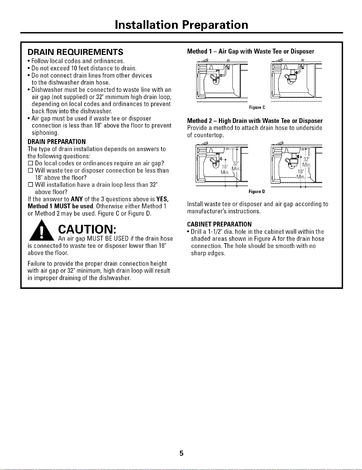
DRAIN REQUIREMENTS
• Follow local codes and ordinances.
• Do not exceed 10 feet distance to drain.
• Do not connect drain lines from other devices
to the dishwasher drain hose.
• Dishwasher must be connected to waste line with an
air gap (not supplied) or 32" minimum high drain loop,
depending on local codes and ordinances to prevent
back flow into the dishwasher.
• Air gap must be used if waste tee or disposer
connection is less than 18"above the floor to prevent
siphoning.
DRAIN PREPARATION
The type of drain installation depends on answers to
the following questions:
[] Do local codes or ordinances require an air gap?
[] Will waste tee or disposer connection be less than
18"above the floor?
[] Will installation have a drain loop less than 32"
above floor?
If the answer to ANY of the 3 questions above is YES,
Method 1 MUST be used. Otherwise either Method 1
or Method 2 may be used. Figure C or Figure D.
CAUTION:
An air gap MUST BE USED if the drain hose
is connected to waste tee or disposer lower than 18"
above the floor.
Method 1 - Air Gap with Waste Tee or Disposer
Figure C
Method 2 - High Drain with Waste Tee or Disposer
Provide a method to attach drain hose to underside
of countertop.
Figure D
Install waste tee or disposer and air gap according to
manufacturer's instructions.
CABINET PREPARATION
• Drill a 1-1/2"dia. hole in the cabinet wall within the
shaded areas shown in Figure A for the drain hose
connection. The hole should be smooth with no
sharp edges.
Failure to provide the proper drain connection height
with air gap or 32" minimum, high drain loop will result
in improper draining of the dishwasher.
5
Page 6

Installation Preparation
PREPARE ELECTRICAL WIRING
WARNING
FOR PERSONAL SAFETY:Remove house
fuse or open circuit breaker before
beginning installation. Do not use an
extension cord or adapter plug with
this appliance.
ATTENTION
SI_CURITI_: Enlever lefusible du circuit
ou d_clencher le disjoncteur avant de
commencer I'installation. Avec cet
appareil, ne pas utiliser une rallonge
ou un adaptateur de prise.
Electrical Requirements
• This appliance must be supplied with 120V,60 Hz., and
connected to an individual properly grounded branch
circuit, protected by a 15or 20 ampere circuit breaker
or time delay fuse.
• Wiring must be 2 wire with ground.
• If the electrical supply does not meet the above
requirements, call a licensed electrician before
proceeding,
Grounding Instructions - Cable Direct
This appliance must be connected to a grounded metal,
permanent wiring system, or an equipment grounding
conductor must be run with the circuit conductors and
be connected to the equipment grounding terminal or
lead on the appliance.
Grounding Instructions - Power Cord Models
This appliance must be grounded. In the event of a
malfunction or breakdown, grounding will reduce the
risk of electrical shock by providing a path of least
resistance for electric current. The plug must be
plugged into an appropriate outlet that is installed
and grounded in accordance with local codes and
ordinances.
WARNING
The improper connection of the
equipment grounding conductor can
result in a risk of electric shock. Check
with a qualified electrician or service
representative if you are in doubt that
the appliance is properly grounded.
Le mauvais branchement du conducteur
de mise _ la terre peut causer des risques
de choc _lectrique. En cas de doute sur
ATTENTION
la mise _ la terre de I°appareil, consulter
un _lectricien agree ou un technicien de
r_paration,
._/I _ l \
-- \
FigureE Black- White
Cabinet Preparation & Wire Routing
• The wiring may enter the opening from either side,
rear orthe floor within the shaded area.
• Cut a 1-1/2" max. dia. hole to admit the electrical cable.
The hole must be free of sharp edges. If the cabinet
wall is metal, the hole edge must be covered with a
bushing,
• Cable direct connections may pass through the
same hole as the drain hose and hot water line, if
convenient. If cabinet wall is metal, the hole edge must
be covered with a bushing, NOTE: Power cords with
plug must pass through a separate hole.
Electrical Connection to Dishwasher
Electrical connection is on the right front of dishwasher.
• For cable direct connections the cable must be routed
as shown in Figure E. Cable must extend a minimum of
24"from the rear wall.
• For power cord connections, install a 3-prong
grounding type receptacle, The power-supply
receptacle for the appliance shall be installed in a
cabinet or on a wall adjacent to the undercounter
space in which the appliance is to be installed.
/ II t \
1-1/2"Dia.
lob (Max.)
t \
from
Cabinet
6
Page 7

Installation Instructions
PREPARE HOT WATER LINE
• The line may enter from either side, rear or floor
within the shaded area shown in Figure E
• The line may pass through the same hole as the
electrical cable and drain hose. Or,cut an additional
1-1/2" dia. hole to accommodate the water line.
If power cord with plug is used, water line must not
pass through power cord hole.
m
Shut-off 1-1/2" Dia.
Valve H
n
Hot[;:::::
ii
From
Cabinet
CabinetFace
FigureF
3" FromFloor
Water Line Connection
• Turn off the water supply.
• Install a hand shut-off valve in an accessible location,
such as under the sink. (Optional, but strongly
recommended and may be required by local codes.)
• Water connection is on the left side of the
dishwasher. Install the hot water inlet line, using
no less than 3/8" O.D. copper tubing. Route the line
as shown in Figure F and extend forward at least
18"from rear wall.
• Adjust water heater for 120°F to 150°F temperature.
• Flush water line to clean out debris.
• The hot water supply line pressure must be
20-120 PSI.
\
CAUTION:
Opening the door will
cause the dishwasher to
tip forward. Do not open the door
until you are ready to install the
dishwasher. If it is necessary to
open the door, hold the top of the
dishwasher securely with one
hand and hold the door with the
other hand.
ATTENTION:
Quand vous ouvrez la
porte, cela fait basculer
vers I'avant le lave-vaisselle.
N'ouvrez jamais la porte avant d'etre pr_t a installer
le lave-vaisselle. Si vous devez ouvrir la porte,
tenez fort le haut du lave-vaisselle avec une main
en ouvrant la porte avec I'autre.
BEFORE YOU BEGIN
Locate and set aside the package containing
2 Phillips head countertop mounting screws
and 2 additional toekick screws (located in
the literature package).
Page 8

Installation Instructions
ISTEP 1 ICHECK DOOR BALANCE
•Tocheckthe doorbalance,holdthe topofthe dishwasherfirmly.
• Openthe door slowly. If the door drops when released,
you will needto increase spring tension. If the door closes
when released, youwill needto decrease tension.
ISTEP 1A I ADJUST DOOR SPRINGS
(IF NECESSARY)
Toadjustthe door springs,youwill needto removethe dishwasher
sidepanels.
Toremovethe side panels:
• Removethe screws fromthetop andbackofeachdishwasher
sidepanel,sixteenscrewstotal. Openthe doorandremovethe
fourscrews securingthe panelsto the insidedoorframe.
S rews
Screws
• If adjustments are needed,see Step1A. If no adjustments are
needed,skip to Step 2.
• Removethe singlescrew just aboveandtothe sideof eachfront
levelingleg.
Figure G
• Laythe dishwasheronits back.Removethe four screws
securingthe toekicktothe dishwasher,andremovethetoekick.
Front
FigureI
Figure H
Rear
FigureJ
• Removethe sidepanelsandsetthe dishwasherupright.
Toadjustthedoorsprings:
• Pullthe springadjustmentpin outoftheholes,insertin the next
highestor lowestholeandtest again.
!
Decrease
FigureK
• Adjustbothdoorspringstothe sametension.
• Continuemovingthe spring pin untildooris balanced.
• Replacethe dishwasherside panelsand proceedto Step 2.
8
Page 9

Installation Instructions
ISTEP 21ADJUST LEVELING LEGS
• Move the dishwasher close to the installation
location and lay it on its back.
/
Adjust to
Installation
Height
FigureL
• Measure installation height and dishwasher height.
Extend leveling legs out from the dishwasher base,
1/4" less than installation height.
ISTEP31REMOVE TOEKICK
• Remove the 4toekick screws, Lift off the 2-piece
toekick,
ISTEP 41 INSTALL POWER CORD
Skip this step if dishwasher will he direct wired.
Use power cord kit WX09X70910 available for
purchase from an authorized GEAppliances dealer.
The power cord and connections must comply with
the National Electrical Code, Section 422 and/or local
codes and ordinances,
• Recommended power cord length is 54" min. and
64" max.
A
Remove
JunctionBox
DUseULListed
WireNuts
FigureN C
• Connect incoming power cord white (or ribbed}
to dishwasher white, black (or smooth)to black and
ground to dishwasher green wire. Use UL listed wire
nuts of appropriate size.
• Replace junction box cover. Be sure wires are not
pinched under the cover.
B CheckThatWhite, Blackand
GreenDishwasherWiresAreThreaded
ThruHolein Back
Ground
]
Black
)wer
CordWiresThru
StrainRelief
and Tighten
FigureM
ISTEP 51 INSTALL 90° ELBOW
• Wrap 90° elbow with thread seal tape.
• Install a 90° elbow onto the water valve.
Fill
Hose
90 o •
Elbow
Water
Valve
Bracket
Thread
Figure0 SealTape
• Do not over tighten 90° elbow, water valve bracket
could bend or water valve fitting could break,
• Position the end of the elbow to face the rear of the
dishwasher.
9
Page 10

Installation Instructions
[STEP 6] POSITION WATER LINE
AND HOUSE WIRING
• Position water supply line and house wiring on the
floor of the opening to avoid interference with base
of dishwasher and components under dishwasher.
House-
Line WNng
FigureP
ISTEP71INSERT DRAIN HOSE
THROUGH CABINET
• Upright the dishwasher and position in front of the
opening. Insert drain hose into cabinet wall hole.
If a power cord is used, guide the end through a
separate hole.
ISTEP 81 SLIDE DISHWASHER
PARTIALLY INTO CABINET
DO NOT PUSH AGAINST FRONTPANELWITH KNEES.
DAMAGE WILL OCCUR.
• Slide dishwasher into the opening a few inches at
a time.
l__s_ as_"_her
byGraspingBothSides
)o Not Push Against
FrontDoor Panel With
Knee.Damage to The
FigureR
• As you proceed, pull the drain hose through the
opening under the sink. Stop pushing when the
dishwasher is a few inches forward of adjacent
cabinetry.
• Make sure drain hose is not kinked under the
dishwasher and there is no interference with the
water line and wiring or any other component.
DoorPanel Will Occur.
With Hands.
Maximum
DrainHose
engthI0'
Insuiati
Blanket
\
Hose
H
Wiring
\\ (If Used)
FigureQ
TIP: Position water line and house wiring on the
floor to avoid interference with base of dishwasher.
PowerCord
10
Page 11

Installation Instructions
ISTEP 91 POSITION DISHWASHER UNDER COUNTERTOP
• Checkto be sure thatwires are secure under the
dishwasher and not pinched or in contact with door
springs or other dishwasher components.
• Push dishwasher into cabinet. The front corners of the
dishwasher door should be flush with cabinet doors.
Be careful not to dent front panel with knees or
damage countertop or cabinets with dishwasher
parts.
__ RepositionDishwasher
_/ , \ byGraspingBoth
-_ I_i SidesWith Hands
DoNot PushAgainst_ _
• Carefully open and close the door to ensure that the
door panel does not catch or rub on the cabinet frame.
• If the door catches or rubs on the frame, reposition
and/or level the unit (see Step 10)until the door moves
freely and does not contact the cabinet frame.
NOTE: If the drain hose gets trapped between the
wall and the back side of the dishwasher, it can prevent
the dishwasher from sliding all the way back into the
cabinet opening, and thus preventing a flush fit with
the kitchen cabinet panels.
NOTE: If this dishwasher is replacing an existing
dishwasher, the old countertop bracket screw holes
may not be in the correct position. New holes may be
required.
ISTEP101LEVEL DISHWASHER
IMPORTANT- Dishwasher must
be level for proper dish rack operation and wash
performance.
• Place level on
door and rack
track inside the \
tub as shown to
check that the Chec
dishwasher is Level-
level, to Back
FigureT
Front
/
Check
Level
fo Side
Front Door PanelWith _. Hi _, _ _/
no .pDaSa vvt.,l; er "
FigureS
• Level the dishwasher
by adjusting the
four leveling legs
individually.
Turn Legs_'_/
to Adjust/
FigureU
TIP: Pull lower rack out, about halfway. Check to be sure
the rack does not roll forward or back into dishwasher.
If the rack rolls in either direction, the dishwasher must
be leveled again.
• If door hits the tub, the dishwasher is not installed
correctly. Adjust leveling legs to align door to tub.
11
Page 12

Installation Instructions
ISTEP 11] SECURE DISHWASHER
The dishwasher must be secured to the countertop
or the cabinet sides, When countertops are made of
wood, use Method 1.When countertops are granite
or other materials that will not accept screws, use
Method 2 to secure dishwasher atthe sides.
NOTE: If desired, drill pilot holes through the
dishwasher holes before inserting screws to minimize
the possibility of damage to cabinets or countertop,
Ii PORTANT - Checktobesure
the dishwasher is centered in the opening and there is
no interference with adjacent cabinets when opening
or closing the door.
Method 1 - Secure dishwasher to wood countertop:
• Fasten the dishwasher to the underside of the
countertop with the 2 Phillips wood screws provided.
ISTEP 12] CONNECT WATER SUPPLY
Connect water supply line to 90° elbow,
• Slide compression nut, then ferrule over end of
water line.
• Insert water line into 90° elbow.
• Slide ferrule against elbow and secure with
compression nut.
FigureX
IMPORTANT-Checktobe sure
that door spring does not rub or contact the fill hose
or water supply line. Test by opening and closing
the door. Re-route the lines if a rubbing noise or
interference occurs.
Figure V
Method 2 - Secure dishwasher with side mounting
brackets:
• Remove plug buttons (one on each side).
• Install screw through the hole in the side of the
dishwasher and into the adjacent cabinet, Reinstall
plug buttons,
FigureW
IMPORTANT- Drive screws
straight and flush. Protruding screw heads will
scratch the top of the control panel and can
interfere with door closing,
12
Page 13

Installation Instructions
[STEP 13] CONNECT DRAIN LINE
FOLLOWALL LOCALCODESAND ORDINANCES.
The drain hose molded end will fit 5/8", 3/4" or 1"
diameter connections on the air gap, waste tee or
disposer. Cut on the marked line as required for
your installation.
CuttingLines
IMPORTANT:Do not cut corrugated FigureY
portion of hose
• If a longer drain hose is required, add up to 42"of
length for a total of 10ft. to the factory installed hose.
Use 5/8" or 7/8" inside diameter hose and a coupler to
connectthe two hose ends. Secure the connection
with hose clamps.
DRAIN LINE INSTALLATION
• Connect drain line to air gap, waste tee or disposer
using either previously determined method.
Method 1 - Air gap with waste tee or disposer
__ re __ re
Waste Tee Installation Disposer Installation
FigureAA
Method 2 - High drain loop with waste tee or disposer
Fasten to underside
__ of countertop,
Fastento underside
_/_ of countertop,
Coupler
HoseClamp
HoseClamp
FigureZ
• Secure the drain hose to the air gap, waste tee or
disposer with clamps.
NOTE: TOTAL DRAIN HOSE LENGTH MUST NOT EXCEED
10 FEETFORPROPER DRAIN OPERATION.
Waste Tee Installation
FigureBB
IMPORTANT Remove
When connecting drain line to
Disposer Installation
-- | Hopper
L_ Plug
disposer, check to be sure that drain plug has been
removed. DISHWASHER WILL NOT DRAIN IF PLUG IS
LEFT IN PLACE.
TIP: Avoid unnecessary service call charges. Always
be sure disposer drain plug has been removed before
attaching dishwasher drain hose to the disposer.
13
Page 14

Installation Instructions
ISTEP 14] CONNECT POWER
SUPPLY
Skip this step if equipped with power cord,
Verify that power is turned off at the source.
• Remove junction box cover "A".
• Locate the three dishwasher wires, (white, black
and green) with stripped ends. Insert dishwasher
wires through the small hole in the junction box "B".
• Secure house wiring to the bottom of the junction
box with a strain relief "C'.
• Use wire nuts to connect incoming ground to green,
white to white and black to black "D'.
• Replace junction box cover "E'. Check to be sure
that wires are not pinched under the cover.
A
Remove
Junction Box
D Use UL Listed
Wire Nuts
FigureCC
E. Replace Junction Box Cover
B Check ThatWhite, Blackand
Green Dishwasher Wires Are Threaded
Ground
Thru Hole in Back
; White
'---__ Black
C
Insert Power
CordWires Thru
Strain Relief
andTighten
WARNING
If house wiring is not 2-wire with
ground, a ground must be provided
by the installer. When house wiring
is aluminum, be sure to use UL Listed
anti-oxidant compound and aluminum-
to-copper connectors.
ATTENTION
Si le circuit de la maison n'est pas
un circuit a deux ills plus fil de terre,
I'installateur doit installer un fil de
terre. Quand le circuit de la maison
est en aluminium, il faut prendre soin
d'utiliser une p_te antioxydante et des
connecteurs aluminium _ cuivre sur la
liste UL
I STEP 15] PRE-TEST CHECKLIST
Review this list after installing your dishwasher to
avoid charges for a service call that is not covered
by your warranty.
[] Check to be sure power is OFF.
[] Open door and remove all foam and paper
packaging.
[] Locate the Owner's Manual in the literature
package.
[] Read the Owner's Manual for operating
instructions.
[] Check door opening and closing. If door does not
open and close freely or tends to fall, check spring
adjustments. See Step 1.
[] Check to be sure that wiring is secure under the
dishwasher, not pinched or in contact with door
springs or other components. See Step 9.
[] Check door alignment with tub. If door hits tub,
level dishwasher. See Step 10.
[] Pull lower rack out, about halfway. Check to be
sure it does not roll back or forward on the door.
If the rack moves, adjust leveling legs.
See Step 10.
[] Check door alignment with cabinet. If door hits
cabinet, reposition or relevel dishwasher. See
Step 10.
[] Verify water supply and drain lines are not kinked
or in contact with other components. Contact with
motor or dishwasher frame could cause noise.
See Step 8.
[] Turn on the sink hot water faucet and verify
water temperature. Incoming water temperature
must be between 120°F and 150°F.A minimum of
120°Ftemperature is required for best wash
performance. See "Prepare Hot Water Line,"
page 7.
[] Add 2 quarts of water to the bottom of the
dishwasher to lubricate the pump seal.
[] Turn on water supply. Check for leaks. Tighten
connections if needed.
[] Remove protective film if present from the control
panel and door.
14
Page 15

Installation Instructions
ISTEP 16] DISHWASHER WET TEST
[] Turn on power supply (or plug power cord into
outlet, if equipped).
[] Turn dial to Normal "Wash" position.
[] Close door.
[] Check to be sure that water enters the dishwasher.
If water does not enter the dishwasher, check to
be sure that water and power are turned on.
[] Check for leaks under the dishwasher. If a leak
is found, turn power supply off, then tighten
connections. Restore power after leak is corrected.
[] Check for leaks around the door. A leak around the
door could be caused by door rubbing or hitting
against adjacent cabinetry. Reposition the
dishwasher if necessary. See Step 9.
[] The dishwasher will drain and turn off about 5to 7
minutes after the first fill. Check drain lines. If leaks
are found, turn power off atthe breaker and correct
plumbing as necessary. Restore power after
corrections are made. See Step 12.
[] Open dishwasher door and make sure most of the
water has drained. If not, check that disposer plug
has been removed and/or air gap is not plugged.
See Step 12. Also check drain line for kinking.
[] Run the dishwasher through another fill and drain
cycle. Check for leaks and correct if required.
[] Atthe end of drain, open door and turn dial to
OFFposition.
STEP 17 REPLACE TOEKICK
UseAdditional2Screws
forInstallationsOver33-1/2"High
FigureDD
• Place 2-piece toekick against the legs of the
dishwasher.
• Place the inner toekick piece (with slots) against
the toekick bracket. The slots should align with
toekick bracket screw holes. Allow the toekick
to touch the floor.
• Place larger toekick over the inner piece and
install 4 toekick screws.
• Use additional 2 screws for installations over
33-1/2" high.
• Use both toekick pieces for all installation heights.
ISTEP 181 LITERATURE
Be sure to leave complete literature package and
installation instructions with consumer.
15
Page 16

NOTE:While performing installations described in this book,
safety glasses or goggles should be worn.
I_)_rMo)wg'ram local s(o-vice i)z )(mr anna, call
1.600.444. l,_4).
NOTE: t roducl improvement is a continuing endeavor
al G(neral Electri(. Tht r(t'_n_e, malerials, appearanc(
and Sl)e(ifi(alions m-¢ stll_jett to (hang( wilhout noti(e.
o 6)
)
Pub.No.31-30571-1 ]
PartNo.20601559Plll
07-04JR
PrintedinChina
Monogram:
J
GEConsumer & Industrial
Louisville, KY40225
@2004GE Company
 Loading...