

Page 1
Installation Sheet No. 1337ZE R3.0
Z630-3 Conventional Optical Smoke Detector
2435-01
Brief description
The Conventional Optical Smoke Detector provides an
early response to a wide range of slow burning to
smouldering fires, and provides reliable sensing for
most conventional fire alarm applications. The detectors
aesthetic design and proven stability in air movements
associated with air conditioning systems, have made it
an ideal selection for modern building interiors.
Specifications
General information
Designation Optical Smoke Detector
Specification EN54 Part 7
Sensitivity 0.1 dB/m
Model number Z630-3
Part number 1337
Compatibility Compatible 24 V conventional
systems
Mounting Plugs into surface or semi
recessed base
Area coverage 80 m², subject to local codes
Wiring 2-wire zonal
Monitoring
Base Open and short circuit by end of
line resistor
Diode base Open and short circuit, and head
out continuity with suitable end
of line (EOL) component.
Indication Alarm LED (red)
Detection principle Photo electric light scatter
Environmental
Application Indoor use
Environmental rating IP32
Temperature range -20 to +70ºC
Humidity range 20 to 95% RH (non condensing)
Primary supply
Operating voltage 12 to 30 VDC
Current (quiescent) <60 µA @ 24 VDC
Current (alarm) Maximum 50 mA (limited by panel)
Mechanical details
Material Moulded ABS
Colour White
Dimensions (D x H) 106 x 52 mm – excluding base
Height (from ceiling
with base) surface base – 60mm
recessed base – 38mm
Weight 100 g (excluding base)
Manufacturer traceability
A barcode label is affixed to each product (see example
below). This label reflects, amongst other things, the date of
manufacture of the product in the form YYDDD.
These numbers are interpreted as follows:
YY = year of manufacture
DDD = day of manufacture
For example the numbers 07134 would indicate that the
product was manufactured on the 134th day of the year 2007,
that is 14
th
May 2007.
Page 1 501-1337ZE-1
www.gesecurity.eu • Copyright © 2007 GE Security B.V. All rights reserved 12 November 2007
Page 2
Installation Sheet No. 1337ZE R3.0
Z630-3 Conventional Optical Smoke Detector
Page 2 501-1337ZE-1
www.gesecurity.eu • Copyright © 2007 GE Security B.V. All rights reserved 12 November 2007
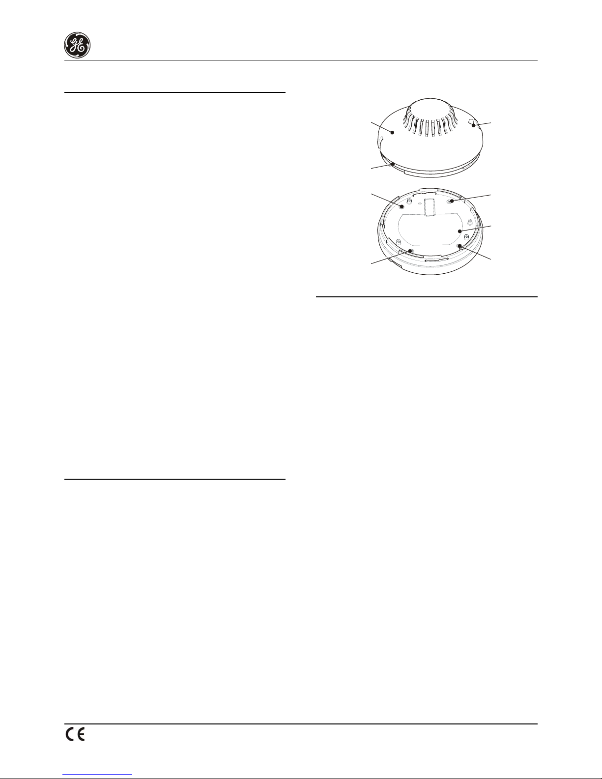
Figure 1: Mounting the detector
Detector Housing
Component
Cover Plate
Component
Cover Plate
Housing Assy
Screw
Housing Assy
Screw
Housing Assy
Screw
Housing Assy
Screw
2437-01
Top View
Bottom View
Indent Zone Labelling
Installation instructions
Note: No wiring is required during detector installation.
Refer to base datasheet for line wiring installation. All
installation should be in accordance with the
requirements of the authority having jurisdiction.
Refer to Figure 1. The detector attaches to compatible
bases with a plug-and-twist action as follows:
1. Align the detector with the base and turn it slowly
until the location lugs and grooves mate, allowing
the detector to slide completely into the base.
2. Rotate the detector clockwise until it locks. To
remove the unit from the base, perform these steps
in reverse order.
Note: To prevent unauthorized removal, a plastic breakout
tab is provided in the detector housing. Once the
breakout tab is removed the detector can only be
released by use of a special tool.
Functional test
3. Prior to initial testing remove the yellow plastic dust
cover from the detector and notify the proper
authorities that the fire alarm system is undergoing
maintenance and will be temporarily out of service.
Refer to local codes prior to testing.
Perform a functional test using an aerosol detector
tester.
4. An indent is provided on the detector exterior for
application of Zone number labelling to allow easy
zone identification.
Warnings: This device detects smoke from slow burning
to smouldering fires, and should only be used
as part of a broad-based life safety system.
For further information consult your local fire
protection specialist.
5. For head out continuity, a diode base must be used
and zone wiring must be terminated with a suitable
end of line (EOL) component. The choice of EOL is
dependant on the control panel used (refer to
Control Panel datasheet). For Control panels
without a head out facility, an active end of line unit
may be used.
Maintenance should be planned in
accordance with the requirements of the
authority having jurisdiction.
Cleaning
Refer to Figure 1.
1. Refer to local codes prior to cleaning.
2. Remove housing screws and the exterior. Remove
the optic chamber by releasing the catch on the
edge of the chamber and twisting the chamber out.
Care should be taken not to damage the insect
mesh window during this operation.
3. Clean the inside of the chamber using compressed
air.
4. Clean the optics and insect mesh windows using
alcohol and cotton buds.
5. Reassemble optic chamber and detector.
6. Check device is functioning correctly.
7. If the device is not functioning correctly, return to
your supplier.
 Loading...