

Page 1
WSLP1500J
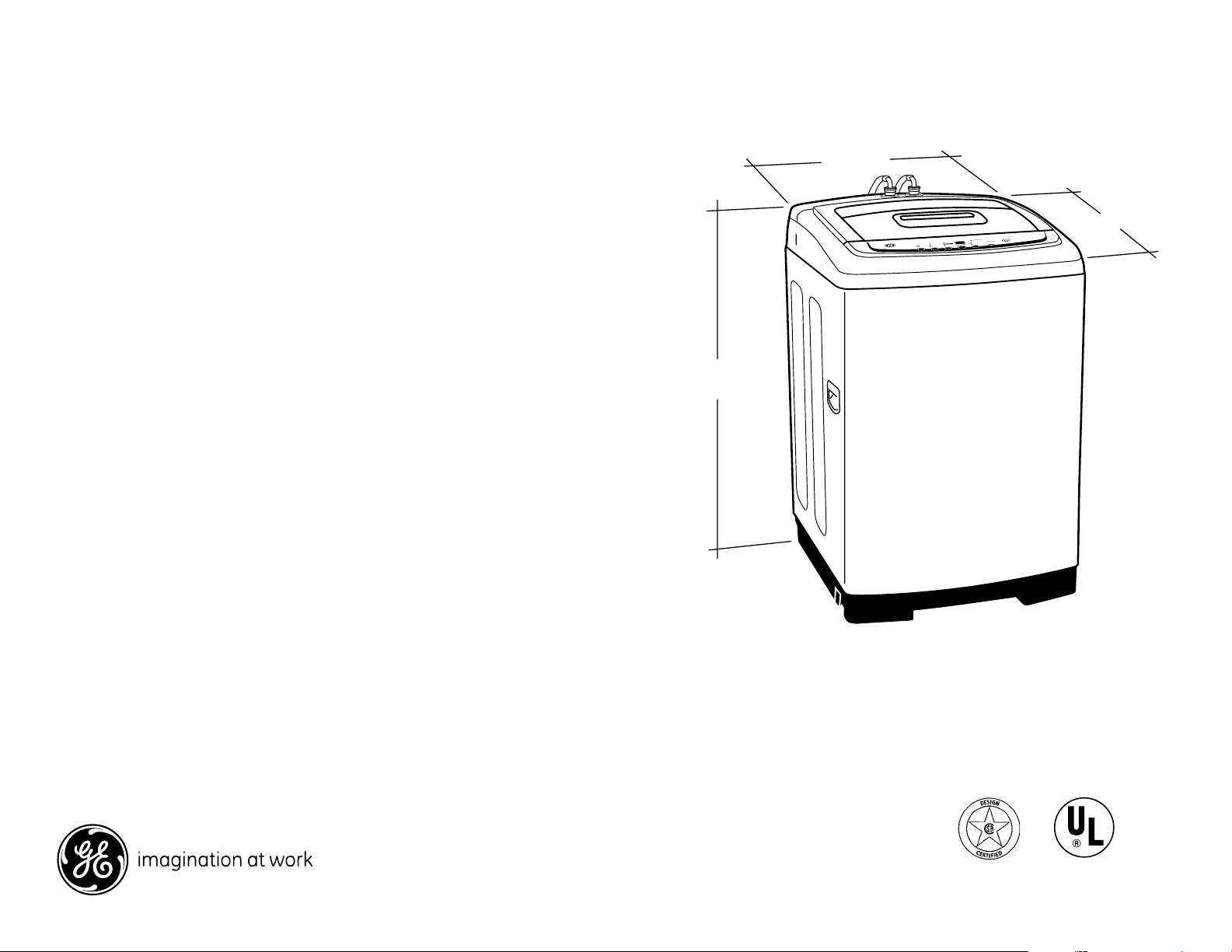
23-5/8”
26”
37-1/2”
GE Spacemaker® Portable Washer
Dimensions and Installation Information (in inches)
Circuit Requirements: An individual, properly-grounded
branch circuit, with a three-prong grounding-type
receptacle, protected by a 15 or 20 amp circuit breaker
or a time-delay fuse, is required.
Electrical Rating: 120V; 60Hz
Washer Note: Washer wall outlet must be located
within 36" of service cord entry. Wall outlet must not
be located behind dryer.
Installation Information: For complete information, see
installation instructions packed with your washer.
®
For answers to your Monogram,
GE® appliance questions, visit our website at
ge.com or call GE Answer Center® service,
800.626.2000.
GE Profile™ or
Specification Revised 10/09
Listed by
Underwriters
Laboratories
360429
Page 2
WSLP1500J
WALL BRACKET
REAR VIEW FRONT VIEW
2 x 4
figure 1
figure 2
1
/8" MAX
20" Max.
Opening
120V 20A or
208-240V 30A
3-3/4
3
3
Rear
Exhaust
5-1/8
8
74-1/8
78
74-1/8
Service
Cord
Entry at
Back of
Appliances
R.H
EXH
5-1/8
4" Dia.
Exhaust
3-1/8
Both
Sides
33-1/4
38
79-1/4
32
2 x 4
2 x 4
6
24-1/2
DSKS433
DSKS333
WSLP1500
WSLS1500
Standpipe
33" Minimum
If Less Than 33"
Use Syphon
Break Kit
WH49X228
26
28
23-7/8
6
120V
15 or 20A
1-1/2
23-5/8
Standpipe
& Faucets
33" Min.
prtbl_stnry_bifl_wshr_inst.eps
46
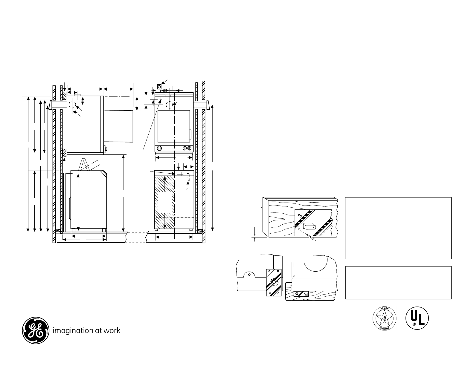
GE Spacemaker® Portable Washer
Dimensions and Installation Information (in inches)
WMK-35 Wall Kit Installation
General Information:
The back of the dryer is not accessible for service or maintenance after
dryer mounting installation is complete. It is recommended that the dryer be
checked and electrical installation completed prior to mounting. For service or
maintenance requiring rear access, the dryer must be removed from the wall.
CAUTION: DISCONNECT ELECTRICAL CURRENT BEFORE INSTALLING OR
SERVICING DRYER.
The electrical outlet must be located above the dryer, or beside the dryer if adequate
dryer-to-wall clearance is available. The outlet must be within three feet on a 240
volt dryer or a 120 volt dryer from the service cord entry on the rear of the dryer.
Dryer Mounting Position
These instructions explain two mounting positions for your 24 inch dryer.
Installation Procedure:
1. Obtain two pieces of 2x4 long enough to span at least two wall studs and the width of the dryer.
2. Locate wall stud center lines. Mark wall stud center lines on two pieces of 2x4 in relationship to
position dryer is to be mounted.
3. Referring to dimensional drawing, draw a horizontal reference line (72") from the floor to locate upper
2x4 support.
4. Position, level and secure upper 2x4 with four 1/4 x 3 inch wood screws. The bottom of the 2x4 should be
positioned on reference line.
5. Referring to dimensional drawing, draw a horizontal reference line 32" down from the bottom of the upper
2x4 support .
6. Position, level and secure lower 2x4 with two 1/4 x 3 inch wood screws. The center line of the 2x4 should be
positioned on reference line.
7. Referring to figure 1, mount the metal wall bracket 1/8 inch from the bottom of the upper 2x4 support with
five 1-1/2 inch wood screws.
8. Referring to figure 2, remove one screw from each lower rear corner of dryer and, using same screws, secure
lower brackets (supplied) as shown.
9. Dryer is supplied with exhaust at the top, locate and install outside exhaust duct referring to the dimensional
drawing. For other optional exhaust directions as shown in dimensional drawing (rear and sides) refer to dryer
installation instruction sheet .
10. Position the dryer on the wall mounting bracket and check that the dryer is plumbed.
11. If the dryer needs plumbing, use some of the twelve washers supplied with the kit as spacers behind lower
brackets of figure 2 and secure the dryer to the lower 2x4 support using the remaining 1-1/2 inch wood screws.
This kit consists of the following:
1 Wall mounting bracket
2 Bottom Brackets
6-1/4 x 3 inch wood screws
Figure 1
7-1/4 x 1-1/2 inch wood screws
12 washers
Dryer Requirements
Carefully read and follow individual dryer installation
instructions for exhausting requirements.
CAUTION
The 120 volt receptacle on the back of
the 240 volt dryer must not be used
with this wall mount kit.
Figure 2
Specification Revised 10/09
Listed by
Underwriters
Laboratories
360429
Page 3

WSLP1500J
GE Spacemaker® Portable Washer
Dimensions and Installation Information (in inches)
Features and Benefits
• Electronic One-Touch Controls with LED Read-Out – Simplify cycle
selection and provide accurate cycle times
• One-Touch Loading Sensing – Eliminates guesswork and helps reduce
water waste
• 14 Wash Cycles – A variety of fabric-specific settings, from extra-
heavy cottons to easy-care colors
• Three Wash/Rinse Temperatures – Offer better wash results and
longer fabric life
• One Wash/Spin Speed – Provides reliable cleaning performance for
regular clothes
• Five Water Levels – Offers water and energy savings
• Stainless Steel Basket – It resists rust and won’t chip, peel or snag
clothes
• Model WSLP1500JWW – White
Specification Revised 10/09
360429
 Loading...