

GE WNCJ2050D0WC, WNCK2050D0WC, WNCK2050D1WC, WNRD2050D1WC, WNRD2050DCWC Installation Guide
...Page 1
i i =ll = i i =• L •
BEFORE YOU BEGIN
Read these instructions completely and
carefully.
IMPORTANT - ObserveaH
governing codes and ordinances.
. Note to Installer- Be sure to leave these instructions
for the consumer's and local inspector's use.
, Skill revel - Installation of this commercial washer
requires basic mechanical and electrical skilrs. Proper
installation is the responsibility of the installer.
Product failure due to improperinstallation is not
covered underthe GEAppliance Warranty.
i i ii
IMPORTANT -I you,eceiveda
damaged commercial washer, you should immediately
contact your dealer or builder.
FOR YOUR SAFETY
Read and observe all CAUTIONS and WARNINGS
shown throughout these instructions.
Hit i= i ==n = i
READ CAREFULLY.
KEEP THESE INSTRUCTIONS.
IPub,No,31-t5558
[Dwg,No,143BB310P032
ND 658-04 (7/03)
Page 2
Installation Preparation
i i i ] i
i i i i
TOOLS YOU WILL NEED:
Socketset
Slip]oint pliers
i i i i
INSTALLATION REQUIREMENTS:
LOCATION
Washer must be installed on firm flooring to minimize
vibration during spin cycles. Concrete flooring is
best, but wood base [ssufficient providedthat floor
support meets FHA standards. Washer should not be
installed on rugs or carpet, be exposed to weather or
temperatures below freezing.
ELECTRICAL AND PLUMBING
REQUIREMENTS
• FORPERSONAL SAFETYDO NOTUSE
AN EXTENSION CORDORADAPTER
PLUGWiTH THIS APPLIANCE.
WARNING
• DONOT,UNDERANY CIRCUM-
STANCE, CUTORREMOVETHETHIRD
GROUNDING PRONG FROMTHEPOWERCORD,
• FOLLOWNATIONAL ELECTRICCODEANSIINFPA
70 ORLOCALCODESAND ORDINANCES.
i i i i ii i
i.iq
i
PLUMBING
•Water Pressure-Must be 10 psi minimum to 150psi
maximum dynamJc pressLire measured at faucet.
•Water Temperature-Water heater should be set to
deliver water at 120°F to 150% (50°Cto 66°C)IN
THEWASHER when HOTwash is selected.
• Shutoff Valves-Both hot and cold shutoff valves
(faucets) should be supplied.
• Drain-Water may be drained into a standpipe or set
tub. The discharge height MUST NOT BE LESS
THAN 30INCHES nor more than 8feet above the
base of the washer. The standpipe must be 1-1/2
inches minimum inside diameter and must be open
to the atmosphere.
i i i
COUNTDOWN DISPLAY
(WCCD AND WLCD MODELS ONLY)
The countdown display shows the remaining time in
the cycle. The display board isconfigured properly at
the factory for the correct cycle timer installed in the
washer. If you wish to change the cycle timer, or add a
debit card interface to the washer, you will need to
change the configuration setting of the countdown
display board as follows.
ON
1 2 3 4
Switch Numbers---]
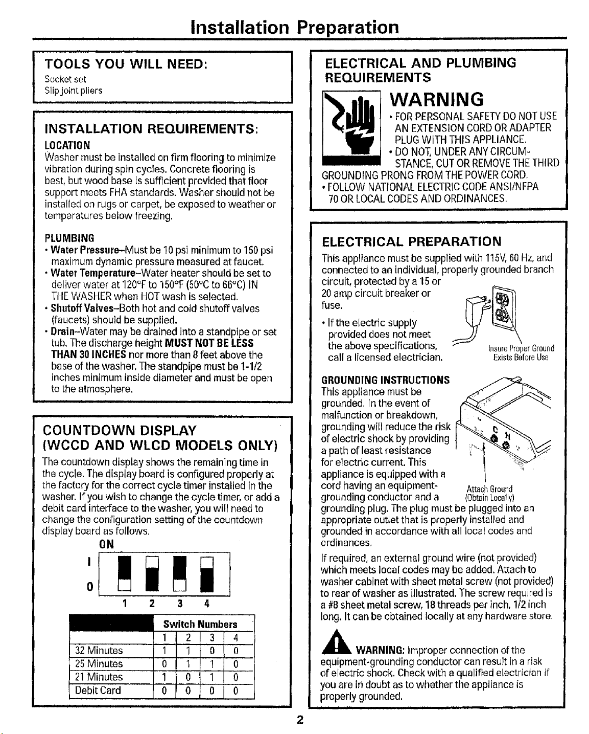
ELECTRICAL PREPARATION
This appliance must be supplied with 115V,60Hz,and
connected to an individual, properly grounded branch
circuit, protected by a 15or
20 amp circuit breaker or
fuse.
• If the electric supply
provided does not meet
the above specifications,
call a licensed electrician.
GROUNDING INSTRUCTIONS
This appliance must be
grounded. In the event of
malfunction or breakdown,
grounding will reduce the risk
of electric shock by providing
a path of least resistance
for electric current. This
appliance is equipped with a
cord having an equipment- AttachGroun_l
grounding conductor and a (ObtainLocally)
grounding plug. The plug must be plugged into an
appropriate outlet that is properly installed and
grounded in accordance with all local codes and
ordinances.
If required, an external ground wire (not provided)
which meets local codes may be added. Attach to
washer cabinet with sheet metal screw (not provided)
to rear of washer as illustrated. The screw required is
a #8 sheet metal screw, 18 threads per inch, 1/2 inch
long. It can be obtained locally at any hardware store,
InsureProperGround
ExistsBefareUse
32 Minutes
25 Minutes
21 Minutes
Debit Card
i i
1 1 0 0 '
0 1
1 0 10 _
o 0
i
,_ WARNING: improper connection of the
equipment-grounding conductor can result in a risk
of electric shock. Check with a qualified electrician if
you are in doubt as to whether the appliance is
properly grounded.
iii
ii ii i
Page 3

i i i
Installation Instructions
ii i i
rSTEP11 PREPARE WASHER ISTEP 3t ATTACH DRAIN HOSE
FOR INSTALLATION TO WASHER
•Grasp shipping rod on MoveWasherClose • Make certain all installation items have been
lower right side (it has a toFinalPosition removed from the washer basket.
tag or strap), and pull Shipping •IMPORTANT'.Remove red plug , Grommet
discard, NOTE',Some water may be
present, this is normal, Plug
rod straight out and Roe from drain hose port. _i_ t /iI,__
Remove inner pack _ Inner secure hose adapter to drain
• hose, Push plastic hose clamp over hose adapter into
and installation _ Pack grooved slot.
under lid, Drain hose is _[ _. _ Water positive click when forced into port. A positive click
in washer basket, __ Hoses(2) will ensure that the proper amount of force has been
[!,:_/1_ \ Drain Hose Drain
• Move washer to | Drain
t
_gor . Locate plastic drain hose
adapter, Place hose clamp over
drain hose on& Insert drain
hose adapter into bent end of
drain hose, Position clamp to
NOTE:This requires some force to install, and has aaccessories from Partsand
applied,
Screws Port
installation location for _ Hose
remaining hose and
Ti Hose Adapter Hose
electrical preparation.
i i i ii iii i ]
ii] i i
ISTEP21ATTACH FILL HOSES
• Push plastic conical end of drain hose adapter into
TO WASHER washer drain hose port. Insert two screws found in
insert rubber washers into both ends of each fill installation pack, and drive screws to mount drain
hose. Attach fill hose marked HOTto hot washer inlet hose to washer,
valve. Attach fill hose marked COLDto cold washer AntisiphanCip
inlet valve. Couplings should be hand
tightened plus 112turn with pliers, _,_!Cab!e tie
ColdWater_ Less
l-lose\ __ Hose _/ _aa..._ _
Water Washers ElectricalCord hose through supplied antisiphon clip and mount to
Hose
...... inserting top clip into top mounting hole and snap
HandTightenPlus 3C)"_'_ : , ]
1/2TurnwithPliers Iti_r_ /
Hose
Cabl_ Drain
NOTE:tf drain hose facility does not meet the 30"
minimum standpipe height requirement, thread drain
cabinet back as shown. Mount antisiphon clip by
second clip into position.
, ii
Page 4

]1 , lu
Installation Instructions
i ii i i i
iiii
ii
i
ii
ISTEP 41 ADJUST LEVELING LEGS
•Ptace level on front top edge of washer,
, Adjust front leveling legs until washer is level from
side-to-side. Remove level,
•Tilt washer forward (pivot on front legs) 4 to 6
inches, This action will set rear leg adjustments to
correspond to front setting.
•Gently set washer back down,
m
TiltWasherForward
4to6 Inchesto Set
ide
ont
LevelingLegs
RearLegAdjustment.
ISTEP 5J INSTALL FILL HOSES
• Be sure water supply lines have been thoroughly
flushed,
•Move washer to final location, DO NOT let fill or
drain hoses drag and get under washer.
!STEP 61 INSTALL DRAIN HOSE
• Insert one end of aluminum drain nozzle into
standpipe,
• Slip or cut wire wrap back approximately 2" below
top of standpipe,
• Cut drain hosejust below standpipe, Place silver
hose clamp over black drain hose end,
• Insert drain nozzle into end of drain hose, and
position clamp to secure drain nozzle to drain hose,
•Install drain hose in drain facility and secure with
cable tie strap provided as illustrated.
Secureto
Hose
CAUTION - BESUREFILL
HOSESAREFIRMLY SECUREDTO FAUCETS.
• Determine which is the HOT water line before
attaching fill hoses to faucets. Traditionally, HOT
faucet is on the left. Be sure rubber washers are in
both ends of washer flit hoses, Connect hose from
inlet valve on washer (marked HOT)to hot faucet
and connect hose from COLDinlet valve to cold
faucet. Couplings should be hand tightened plus
t/2 turn with pliers.
HandTightenPius
1/2TurnwithPliers
,o
t _ scr=_ _. Cold
Water.. L=IRubber"Water
Hose "-_ wa_ Hose
CableTie Hose
Drain
NOTE:Drain hose nozzle may be shortened if original
length prevents full insertion into drain facility.
CAUTION - BESURE
DRAIN HOSEIS TAPEDORSECUREDTO STANDPIPE
OROTHERDRAIN FACILITY.
NOTE:Water may be drained into astandpipe, The
discharge height must not be less than 30 inches, nor
more than 8 feet above base or washer. Standpipe
must be 1-1/2" minimum inside diameter and must be
open to atmosphere.
4
Page 5

i
i
Installation Instructions
= = = = i
ISTEP 71 ECONOMY WATER USAGE
The pressure sw tch sset nthe factory for the high
water level and usage,
Tochange setting from high water level to medium or
low:
WARNING - MA*E
SUREWASHER IS UNPLUGGED FROM ELECTRICAL
OUTLET.
• Remove 4 torx screws from back of control panel
and lay control panel front on cover.
Remove
. Fromthe front, move white plastic cam on pressure
switch inthe clockwise position with your finger
until it clicks over into the medium or low water
position, (See illustration below,)
RotaLe
kwise
[STEP 9] SPECIAL INSTRUCTIONS
COVERSECURITYLOCK INSTALLATION
Washer cover is designed to accept stud type lock
as shown below,
518"
5/16"-t8 Thread
I_- i-1/16"-"-I %arVbw
CamLockAvailable.__
FromGreenwald
Part#8-I222
To install lock:
• Remove plastic insert infront of cover,
•Install the lock washer on the lock shaft and locate
so that the lock can be engaged in a counterclock-
wise direction.
• Insert lock mechanism into cover opening and
tighten until snug. (Overtightening may damage
painted surfaces.)
• Install cam and tighten until snug,
ACCESSDOORLOCKINSTALLATION
Toremove the access door retainer before installing
a lock, place the door over a wood block with a t/2"
hole drilled in it and tap end of screw lightly with a
hammer.
!-*-L_f
11mF
i iJ i
i ii i i i i
ISTEP 81 ELECTRICAL CONNECTION
CAUTION -BEFORE
PLUGGING IN APPLIANCE, READ ELECTRICALAND
PLUMBING REQUIREMENTSAND CHECKLIST,
Plug electrical power cord into a properly grounded
wall outlet.
_-Wood
Bock
_) -SpringWasher
Nut_,,._l,._am
Nut
LockWasher
Page 6

Installation Instructions
ii i
i i i i i i
[STEP 1OI CHECK LIST
Review this list after installing the washer to avoid a
charge for a service call not covered by the warranty,
i
i i
i ii i i.i i ii
ii ii i ii ii
WARNING
Foryoursafety,the informationin these instructions mustbe
followed to minimizethe risk of fire or explosion, electric shock,or to
prevent property damage,personal Injury,orlossof life.
AFTER INSTALLATI0 N CH ECK TtIE FOLLOWI NG:
[] Drain hose must be pulled tight and secured to
drain facility to prevent lifting out of drain facility
during discharge, Nozzle clamp must be securely
tightened to prevent leaks. MAKE SURE DRAIN
HOSE IS NOT RUBBING AGAINST CONCRETE OR
BLOCK WALL. RUBBING MAY WEAR HOLES IN
HOSE.
[] Hose Washers-Rubber washers in both ends offitl
hoses.
El Hose Connections-Hot side (left valve) connected
to hot water supply, cold side (right valve) to cold
water supply. All connections should be hand
tightened plus 1/2 turn with pliers.
[] Grounding-Must be properly grounded to conform
to !ocal codes and ordinances.
[] Leveling-Adjust front leveling legs as necessary
(preleveled from the factory at 1"). Check side to
side and front to back. Tilt forward approximately
4" to adjust rear self-leveling legs.
[] 0peration-Turn on faucets and run washer com-
pletely through cycle by hand. Check for leaks,
noise, vibration, correct water temperatures and
proper operation in wash and spin. While washer
is in spin, raise lid and check Lid switch and brake
operation,
i
i i
ISTEP 11t LITERATURE
• Be sure to leave complete literature package and
installationinstructions with consumer.
IL i
i i iji ii ii i i
TYPICAL HOSE INSTALLATIONS:
WATER HEATER SAFETY
• Undercertain conditions hydrogengas maybe produced ina
water heater that has not been usedfor two wealdsormore.
Hydrogengas can be explosive under these circumstances.
• tf the hot water has not beenused for twoweeks or more,prevent
the possibility ofdamageor injury byturning onall hotwater
faucets andallowing them to run for several minutes.Dothis
before using any electrical appliancewhich isconnected tothe
hot water system.This simple procedure will allow anybuilt-in
hydrogengas to escape, Sincethe gas is flammable,do not smoke
or usean openflame or appliance duringthis process.
YOUR LAUNDRY AREA
•Keep the areaunderneath and aroundyourappliances freeof
• combustible materials such as lint,paper,rags,chemicals,etc.
Closesupervisionis necessary if this appliance is usedbyor near
children. Donot allow children te play on.with, or insidethisor
any other appliance.
WHEN USING THE WASHER
•Never reach intowasher while itis moving.Wait until the machine
has completely stopped before opening the _id.
•Do not mix chlorine bleachwith ammonia or acidssuch asvinegar
and/or rust remover. Mixing different chemicals can produce a
• toxic gaswhich maycause death,
Do not washor dryarticles that have beencleaned in, washed in,
soakedin, or spottedwith combustible or explosivesubstances
(suchaswax, oil, paint, gasoline, degreaaers,dry-cleaning
solvents,kerosene,etc.). Thesesubstancesgive offvaporsthat
may ign_taor explode.Do not add these substancesto thewash
water. Donot use or place these substances aroundyourwasher
or dryer during operation.
. Thelaundry process can reduce the flame retardancyoffabrics. To
avoidsuch a result,carefully follow the garmentmanufacturers
wash and care instructions.
• Tominimizethepossibility of electric shock, unplug this appliance
fromthe power supply or disconnect thewasher at the household
distribution panel by removing the fuse or switching off thecircuit
breaker beforeattempting anymaintenanceor cleaning.NOTE:
Turningthe Cycle Selector knobto anoff positiondoesNOT
disconnect the appliance from the power supply.
, Never attemptto o.j3eratethis appliance if it isdamaged,malfunc-
tioning,partially disassembled,or has missingor brokenparts,
including a damagedcord or plug.
WHEN NOT IN USE
• Turnoffwater faucets to relieve pressure onhosesand valvesand
tominimize leakageif a break or rupture should occur.Checkthe
condition ofthefill hoses;theyshouldbe replaced every5years.
• Before discardinga washer,or removingit from service, remove
the washer lid to prevent children fromhidlng inside.
• Donot attempt torepair or replaceany partof this appliance
unless specifically recommendedin these instructions or in
published user-repair instructions that youunderstandandhave
the skills tocarry out.
• Donot tamper with controls.
U
TypicalCompletedWasherAssembly
II J III
SPE01FICATIONSSUBJECTTOCHANGEWITHOUTNOTIOE
READ AND FOLLOW THIS SAFETY
INFORMATION CAREFULLY.
SAVE THESE INSTRUCTIONS
 Loading...