

Page 1
Technical Bulletin
GE Appliances
SmartCard System
WNCJ2050AWC
WNCK2050AWC
Commercial SmartCard Washer
TO REDUCE THE RISK OF
WARNING
• The power must be disconnected before servicing by unplugging the
machine or disconnecting the circuit breaker.
• The machine must be electrically grounded through the grounding
lead in the three-prong power cord. The cord must be plugged into a
properly installed and grounded appliance outlet. If local codes
require an additional ground connection, use a 16-gauge or larger
wire to connect the washer cabinet to an established ground. In all
cases the grounding method must comply with all local codes and
ordinances.
IMPORTANT - RECONNECT ALL GROUNDED DEVICES
IF GROUNDING WIRES, SCREWS, STRAPS, CLIPS, NUTS OR WASHERS USED
TO COMPLETE A PATH TO GROUND ARE REMOVED FOR SERVICE, THEY
MUST BE RETURNED TO THEIR ORIGINAL POSITION AND PROPERLY
FASTENED.
IMPORTANT SAFETY NOTICE
THIS INFORMATION IS INTENDED FOR USE BY INDIVIDUALS POSSESSING
ADEQUATE BACK-GROUNDS OF ELECTRICAL, ELECTRONIC AND
MECHANICAL EXPERIENCE. ANY ATTEMPT TO REPAIR A MAJOR APPLIANCE
MAY RESULT IN PERSONAL INJURY AND PROPERTY DAMAGE. THE MANUFACTURER OR SELLER CANNOT BE RESPONSIBLE FOR THE INTERPRETATION
OF THIS INFORMATION, NOR CAN IT ASSUME ANY LIABILITY IN CONNECTION WITH ITS USE.
This document provides the following technical information for GE SmartCard washer models WNCJ2050 and
WNCK2050:
• Introduction
• Features
• Accessing Components
• Troubleshooting and Service Information
• Wiring Diagram
ELECTRICAL SHOCK:
Introduction
The GE models WNCJ2050 and WNCK2050 introduce
SmartCard technology to the GE commercial laundry
line. SmartCard technology allows commercial laundry
establishments and customers to conduct commercial
transactions without hard currency. This technology
uses a memory chip based card that can store all the
necessary transaction information and provides the
consumer great convenience and flexibility. The
SmartCard system also provides owners of commercial
establishments improved security and added managerial
features as well as greater flexibility.
To use the card, the user would insert the card into a
special central vending station along with a money
deposit that will credit the SmartCard. The machine
encodes credit for the amount of money deposited onto
the card. The user then takes the card to the washer,
inserts the card and selects the wash cycle. Based on
the cost of the cycle, the card reader in the washer
deducts that amount from the card. When the total
amount on the card has been used, the card is inserted
back into the vending station where additional credit
may be added to the card for the amount of money
deposited.
GE Washer WNCJ2050 and WNCK2050 contain a
SmartCard reader located to the right of electronic
Control Panel. WNCJ2050 uses the BridgePoint SmartCard control reader. WNCK2050 uses the ESD SmartCard
control reader. A keypad electronic washer control has
been added to the model line to improve ease of use
and serviceability. The main wash functions are still
accomplished through a two-speed motor, hot and
cold water valves and a pump. The components are
controlled by the electronic control, the dual pressure
switch, and the keypad selector switches. The L3D
electronic control consists of a printed circuit board,
transformer and housing.
As detailed in the product warranty, the SmartCard
control reader is serviced by the reader’s original
equipment manufacturer. In cases where the field
service diagnostics indicates the error code EO (serial
communication – external), the user should contact the
reader original equipment manufacturer for service at
the following numbers:
Model WNCJ2050 BridgePoint: 1-800-562-5875
Model WNCK2050 ESD: 1-770-425-6298
Features
• Super Plus 2.7 cu. ft. Capacity
• 3 Wash/Spin Speed Combinations
• 3 Wash/Rinse Temperatures
• Automatic Water Levels
• Digital Cycle Countdown with LED indicators
• 5 Wash Cycles: Cottons - White, Colored; Bright Colors;
Permanent Press; Delicates
• BridgePoint SmartCard Reader with Alphanumeric
Display and Control Card (WNCJ2050)
• ESD SmartCard Reader with Alphanumeric Display and
Control Card (WNCK2050)
• Lid Instructions
Page 2
Accessing Components
SmartCard Reader – Removal and Replacement
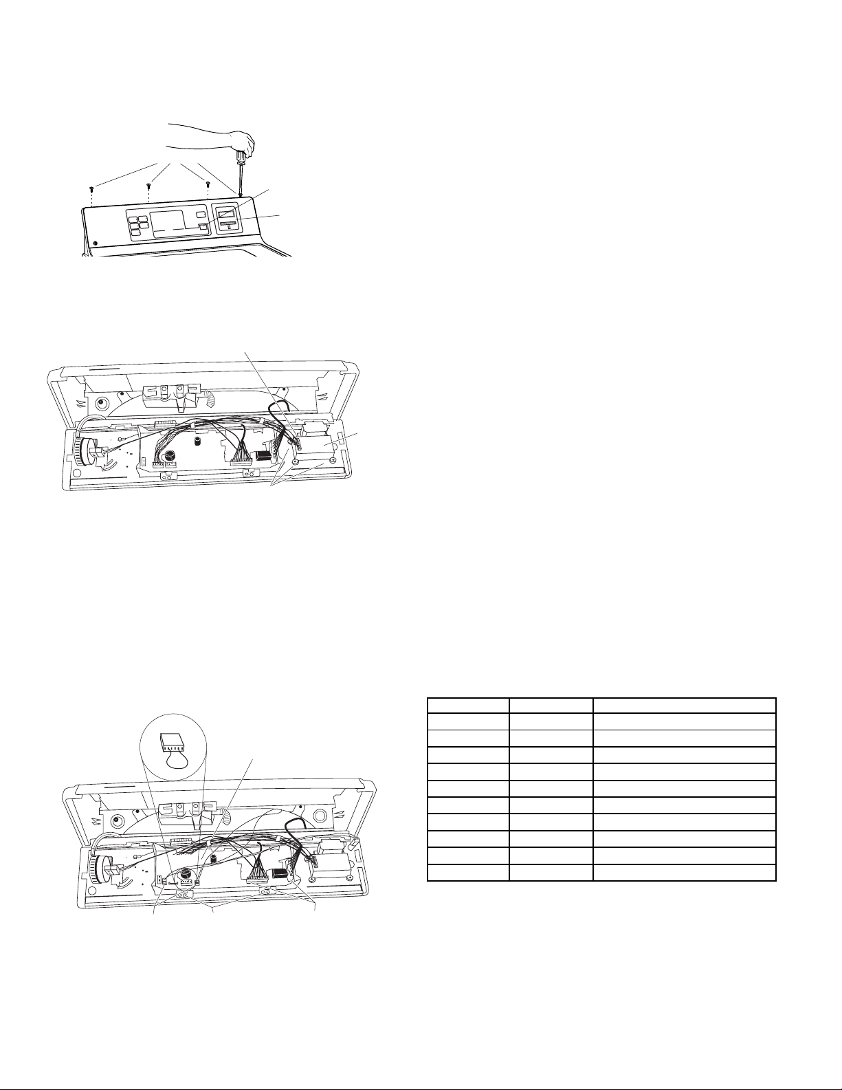
1. Remove four screws from top panel and pull forward.
Remove 4 Screws
/RINSE SPEED
ASH
W
TEMPERATURE
CLOTHES CARE SELECTION
RMAL/SLOW
NO
PERM
SH
A
HOT W
E
HIT
S
W
RES
P
NS
TTO
CO
ENTLE/SLOW
G
ASH
M W
AR
W
S
TE
ST
A
ELIC
D
AL/FA
RED
LO
ORM
CO
N
ASH
COLD W
NS
OTTO
C
STATUS
BRIGHT
LORS
CO
AL SP
FIN
SE
RIN
ASH
W
FILL
D
S
E
y
b
E
D
I
L
S
d
r
a
C
START
E
M
I
T
T
S
E
G
N
I
N
I
A
M
E
R
ISHED
FIN
IN
Dual Seven
Segment Display (DSSD)
SmartCard
Reader
2. Remove the four corner screws from the SmartCard
Reader.
3. Remove connector cable from reader.
4. Reverse the above procedure to reinstall.
Connector Cable
SmartCard
Reader
Remove 4 Screws
Electronic Control Board – Removal and Replacement
1. Follow step 1 above.
2. Remove 4 harness connections. Remove and retain the
model selector harness plug for reassembly.
3. Remove 2 screws (1/4-in) from the control board.
CAUTION: To prevent electrostatic discharge, ground
yourself to the washer cabinet or use an ESD wristband.
4. Remove the electronic control board.
Note: When reassembling, align the LEDs with the
appropriate control panel indicators.
5. Reverse the above procedure to reinstall.
Model Selector/
Service Selector
Harness
Remove Harness
Connections (2)
Electronic
Control Board
Screws
(2)
Remove Harness
Connections (2)
Field Service Mode
T
he Field Service Mode for L3D controls allows the field
service technician to test the inputs and outputs of the
control. It also allows the technician to step through the
test cycle and operate components on the washer.
The Field Service Mode can be entered manually or by
inserting a special Service Mode card (available to commercial laundry owners) into the SmartCard reader.
Manual entry into the Field Service mode requires the Model
Selector harness WD21X10026, to be installed into the L3D
control. This is the Service Selector harness. To install the
Service Selector harness, disconnect power to the machine
and remove the currently installed Model Selector harness.
Save the removed Model Selector harness for reinstallation
after service. Install the Service Selector harness into the
control board and reconnect power to the machine. Note:
When the service operation is completed, remove the
Service Selector harness and reinstall the previous Model
Selector harness.
After reconnecting power, the L3D control test cycle is
entered by pressing and holding the White Cotton and the
Start button simultaneously for 3 seconds. As soon as the
test cycle is entered, the control will power the Dual Seven
Segment Display (DSSD) to output the letters Fd (Field
Service Diagnostics).
Manual entrance into Field Service mode will be restricted to
the time period of 15 seconds after Power-On-Reset of the
L3D electronic control. Following this time, the key sequence
method of entry into the service mode will be disabled.
The service mode may also be entered by receiving the
appropriate command via the serial communication port
using the Service Mode Card. Entry into the Field service
mode will be allowed at any time the machine is powered
and in the idle state.
When any of the above buttons are pressed or when the
pressure switch is pushed or contacted, the control will beep
for 0.5 seconds.
The initial step after entering service mode for the L3D
electronic control will be defined as Step 0. This will
signal the DSSD to output Fd and the control will light all
LEDs. The following table gives required functions for
subsequent steps. To proceed to the next step, press the
Color Cottons pushbutton. To return to the previous position,
press the White Cottons.
DSSD
Position Output Function
0-Initial Fd LED Check
1 ** Model Code
2 E# Error Codes
3 H Hot Water Valve Active
4 C Cold Water Valve Active
5 AL Slow Agitate (Dry)
6 AH Fast Agitate (Dry)
7 P Pump
8 SP Spin
* ➔ Indicates model number
# ➔ Indicates number of error code if there is more than
one error, each error will display for 2 seconds, followed
by the next error)
This feature holds true for all tests with exception of the
serial communication test. The serial communication test
can be run only once due to the limited time required to
run the test. Once the serial communication test has
been run, the operator must exit and reenter the mode to
repeat the test.
2
Page 3
The lid switch will affect the LEDs by deactivating any
active LED in the service mode for L3D control when the
lid is raised. This allows the technician to determine if
the switch is working.
Service Mode Error Codes
E1 EEPROM Error
E2 Thermistor Error
E3 Flood Condition Detected Error
E4 Slow Pump Error
E5 Never Fills Error
E6 Pump Detection Circuit Error
E7 Pushbutton Error (shorted pushbutton)
E8 Pressure Switch Error
E9 Serial Communication – L3D Internal
E0 Serial Communication – External
If you are in the Error Codes Function Display and you
press the Start pushbutton, then the control will clear all
errors.
If you are in the Model Code Function Display and you
press the Start/Pause pushbutton, the control will
display the EEPROM Revision contained in the EEPROM
only while the button is depressed.
If you are in the Hot Water Valve Active Display and you
press the Start/Pause pushbutton, the control will
display the ROM Revision of the software only while the
button is depressed.
The service mode will allow the technician to operate
the washer in dry agitate. However, if the washer is
placed in either agitate function during the diagnostics
and the Start pushbutton is pressed for 2 seconds the
dry agitate will become wet agitate. This wet agitate
stops the motor, and energize the cold water valve until
the pressure switch is made. To determine if the pressure switch is working correctly, the control turns on
wash temperature LEDs in sequential order from the
smallest load size LED to the largest load size LED. For
example, the Cold Wash size LED will represent a small
load and the Hot Wash size LED represent a full basket
of water. After the tub has reached the full basket, then
the washer resumes agitation.
When advancing through the service mode functions,
energizing LEDs and the accompanying beeps will occur
immediately. However, a 0.5-second delay will occur
before initiating the new function. The sequence of
events are: the previous function will stop; the LED for
the previous function will deactivate; the LED for the
new function will activate and the beeper will beep; one
(1) second will pass and the new function will begin. This
will allow the technician to hear one function stop and
another start.
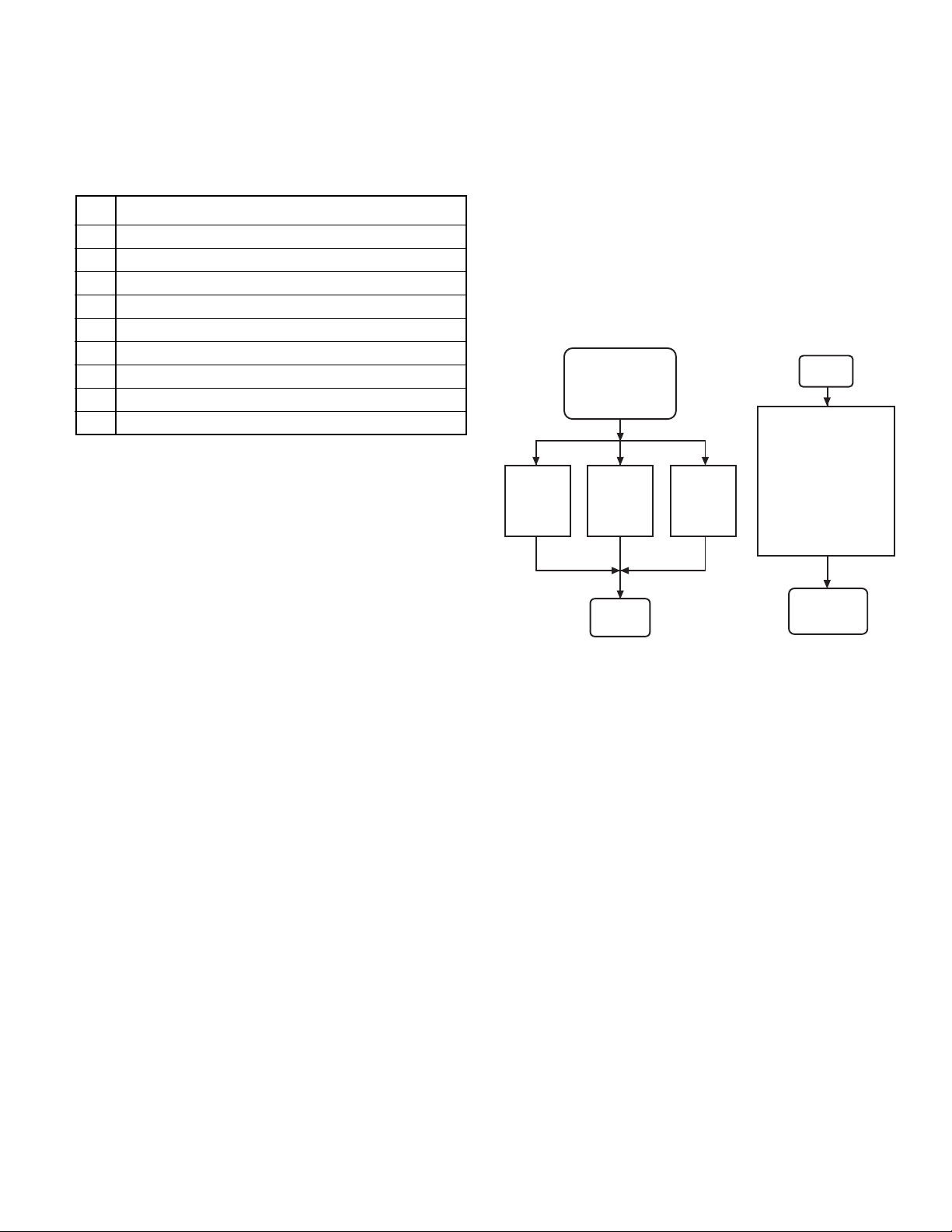
Termination of the Service Mode can be Accomplished
in Three Ways:
1. The user may remove power by unplugging the unit.
2. The control will exit the S1 – Field Service Mode 30
minutes after the beginning of the Mode.
3. Removal of the Service Mode Card
By removing the Service Mode Card, the DCR will
recognize that the service mode is terminated. The DCR
will transmit a Stop command to the L3D control to
return the L3D to the idle state.
L3D Field Service Mode
Entrance/Exit
Field
Service Mode
Removal
of
Service
Card
30 min
time-out
from
start of
mode
Idle
Loss of
Power to
Control
Diagnostics
The control provides diagnostics to inform the operator
of the current status of the washer. The LEDs displayed
to indicated the fault will flash at a rate of 1 hertz.
Serial Communication Diagnostic Test
To perform the serial communication diagnostic test, the
L3D control will issue a request to the DCR for its software version number. Verification of the transmitted
packet data will confirm the serial communication
hardware on the L3D is functional. Alternatively, reception of a machine status request command from the DCR
will also be considered sufficient to demonstrate functional serial communication hardware. If no status
request is received and there is either no response to
the DCR version number request or the response is
invalid, then an external communication error will be
assumed, generating a E0 error code on the DSSD.
If the external communication test fails, the L3D control
will perform a loop-back test by verifying the transmitted
packet data is also seen upon the RxD pin on the microprocessor. A failure in the loop-back test indicates a
potential failure on the L3D hardware or a short circuit
on the Data Comm I/O line, yielding an E9 fault.
3
Idle
Initiate field Service
Mode by using the
Service Mode card
or simultaneously
pressing and holding
the Start and
the White Cotton
pushbuttons with the
Service Selector
Harness inserted
Field
Service
Mode
Page 4

Troubleshooting Flowcharts
Component Operation Troubleshooting
Initiate field Service Mode by using
the Service Mode card
or simultaneously pressing and
holding the Start and the
White Cotton pushbuttons with
the Service Selector
Harness inserted
DSSD output displays Fd
Press Colored Cotton button
3 times
DSSD output displays H
Hot water valve is activated
Press Colored Cotton button
DSSD output displays C
Cold water valve is activated
Press Colored Cotton button
DSSD output displays AL
Slow agitate (dry) is activated
Press Colored Cotton button
Press Start button
for 2 seconds
Slow agitate
(wet)
Press Colord Cotton
button to
return to Fd
DSSD output displays AH
Fast agitate (dry) is activated
Press Colored Cotton button
DSSD output displays P
Pump is activated
Press Colored Cotton button
DSSD output displays SP
Spin is activated
4
Press Start button
for 2 seconds
Press Stop button
Fast agitate
(wet)
Exit field
service mode
Page 5

Error Code Troubleshooting
Washer
Proper voltage to
Washer
Yes
Initiate field Service
Mode by using
the Service Mode card
or simultaneously
pressing and holding
the Start and the
White Cotton
pushbuttons with
the Service
Selector Harness
inserted
No
Test
Mode
House fuse,
breaker, or wall
outlet problem
DSSD output
displays Fd
Lift lid, Cycle
Status, LEDs will go
OFF (confirms lid
switch operation)
Yes
Press Colored
Cotton button - DSSD
output indicates
model code
Check error codes
Press Colored
Cotton button - DSSD
ouput displays
error codes for
existing errors
No
NOTE: If control is operating, it is
likely that the control is not faulty.
Record all the error codes and
recheck error message at the
component level. Record errors on
the call sheet.
Check lid switch and contact
Replace if faulty
EEPROM faulty - Replace PC board
E1
Thermistor faulty or disconnected (if
present) - Check resistance (50k
E2
E3
E4
ohms) - Replace if faulty
Flood - Check water valves, pressure
switch - Replace if faulty
Slow pump - Check pump, standpipe
height and drain - Look for pump
obstructions - Replace pump if faulty
Press Stop to exit
field service mode
Press Colored
Cotton button to
proceed to Component
Operation
Troubleshooting
*If high level pressure switch is opened before low, or if
high pressure closes before low, the E8 error code is
displayed. If during the 20 second pump out, the high
pressure switch does not reset (opened to normally
closed), E8 is generated.
No fill - Check water is on, check
water valves, pressure switch-
E5
E6
Stuck Pushbutton - Replace PC board
E7
E8*
E9
Check SmartCard to PC board
connector harness and SmartCard
control reader - if faulty change
harness or SmartCard control reader
E0
by contacting reader manufacturer at:
BridgePoint: 1-800-562-5875
ESD: 1-770-425-6298
Replace if faulty
No pump - Check for pump
obstructions, operation - Replace
pump if faulty
Pressure switch faulty or
dicconnected-
Replace if faulty
Check serial port in PC board-
If faulty, replace PC board
5
Page 6

Wiring Diagram
Selector harness plug options:
09 for short wash cycles
01 for long wash cycles
14 Service Selector Harness
1
2
3
4
OX
5
6
7
DEBIT CARD
READER
VW
YX
RX
WX
NX
RW
0121110 9 8 7 6 5 4 3 2 1 0
NX
OX
TX
VX
BX
WR
WX
YR
321
RX
1234567
SELECTOR
HARNESS
PLUG
START
WX
NX
YX
CONTROL CIRCUIT BOARD
LID
COM
SWITCH
11
M2
M3
START
M7
M1
MOTOR
HIGH
LOW
M6
M5
16
HI
LOW
12
WATER
LEVEL
SWITCH
WATER LEVEL SWITCH
BEFORE DISCONNECTING HOSE FROM
WATER LEVEL SWITCH. BE SURE
WATER LEVEL IN MACHINE IS
BELOW BOTTOM OF WASH BASKET.
AFTER RECONNECTING HOSE, PUT
MACHINE IN SPIN FOR AT LEAST
ONE MINUTE BEFORE CHECKING
WR
N
PUMP
RR
RS
M
LI
OPERATION OF SWITCH.
COLOR CODE
LETTERS COLOR
AX
LT. BLUE
BX
BLACK
CX
BROWN
NX
DK. BLUE
OX
ORANGE
PX
PINK
LETTERS COLOR
RX
RED
SX
GRAY
TX
TAN
VX
PURPLE
WX
WHITE
YX
YELLOW
THE "X" INDICATES ONE SOLID COLORNO TRACER. WIRES WITH TRACER SHOW
BOTH COLORS. EXAMPLE -WR IS WHITE
WITH RED TRACER.
6
Page 7

Notes: _____________________________________________________________________
__________________________________________________________________________
__________________________________________________________________________
__________________________________________________________________________
__________________________________________________________________________
__________________________________________________________________________
__________________________________________________________________________
__________________________________________________________________________
__________________________________________________________________________
__________________________________________________________________________
__________________________________________________________________________
__________________________________________________________________________
__________________________________________________________________________
__________________________________________________________________________
__________________________________________________________________________
__________________________________________________________________________
7
Page 8

GE Commercial Washer Warranty.
Coin-Operated and Smart Card-Operated Models
Parts and service are available from your General Electric
Commercial Laundry distributor.
For The Period Of: We Will Replace:
Three Years Any part of the washer which fails due to a defect in materials or workmanship. During this
From the date of the limited three-year warranty, you will be responsible for any labor and related service costs.
original purchase
Five Years The outer tub and inner basket, if either of these parts should fail due to a defect in materials or
From the date of the workmanship, and the cabinet side panels, base and cover, if they should fail due to rust-through.
original purchase During this limited additional two-year warranty, you will be responsible for any labor and related
service costs.
What Is Not Covered:
■ Coin drop meter, coin slide mechanism, coin vault and
locks, smart card modules and cards, smart card system
accessories.
■ Service trips to your place of business to teach you how
to use the product.
■ Improper installation.
■ Failure of the product if it is abused, misused, or used for
other than the intended purpose.
■ Any and all implied warranties of merchantability and
fitness for a particular purpose.
■ Replacement of fuses or resetting of circuit breakers at
place of business.
■ Damage to the product caused by accident, fire, floods
or acts of God.
■ Incidental or consequential damage caused by possible
defects with this appliance.
This warranty is extended to the original purchaser and any succeeding owner for products purchased for commercial
use within the USA. In Alaska, the warranty excludes the cost of shipping to your place of business.
Some states do not allow the exclusion or limitation of incidental or consequential damages. This warranty gives you
specific legal rights, and you may also have other rights which vary from state to state. To know what your legal rights
are, consult your local or state consumer affairs office or your state’s Attorney General.
Warrantor: General Electric Company. Louisville, KY 40225
Pub. No. 49-90149
Dwg. No. 175D1807P412
N.D. 368-11
8
 Loading...