

Page 1
GE Consumer & Industrial
Technical Service Guide
DECEMBER 2005
GE Front Load
Washer
31-9135
WBVH6240
WCVH6260
WHDVH626
GE Appliances
General Electric Company
Louisville, Kentucky 40225
Page 2

IMPORTANT SAFETY NOTICE
The information in this service guide is intended for use by
individuals possessing adequate backgrounds of electrical,
electronic, and mechanical experience. Any attempt to repair a
major ap pli ance may result in personal injury and property
damage. The man u fac tur er or seller cannot be responsible for the
in ter pre ta tion of this in for ma tion, nor can it assume any liability in
connection with its use.
WARNING
To avoid personal injury, disconnect power before servicing
this prod uct. If electrical power is required for diagnosis or test
purposes, disconnect the power immediately after performing the
necessary checks.
RECONNECT ALL GROUNDING DEVICES
If grounding wires, screws, straps, clips, nuts, or washers used to
complete a path to ground are removed for service, they must be
returned to their original position and properly fastened.
GE Consumer & Industrial
Technical Service Guide
Copyright © 2005
All rights reserved. This service guide may not be reproduced in whole or in part
in any form without written permission from the General Electric Company.
– 2 –
Page 3

Table of Contents
Basic Wash Cycle ............................................................................................................................................................. 18
Component Locator Views ........................................................................................................................................... 20
Control and Inverter Board Connections ...............................................................................................................22
Control Board ......................................................................................................................................................................25
Control Features ................................................................................................................................................................ 6
Control Panel ..................................................................................................................................................................... 24
Dampers ............................................................................................................................................................................... 46
Dispenser Assembly ........................................................................................................................................................ 29
Dispenser Motor ................................................................................................................................................................ 32
Door ....................................................................................................................................................................................... 42
Door Hinge ........................................................................................................................................................................... 44
Door Lock .............................................................................................................................................................................26
Door Strike ............................................................................................................................................................................ 27
Error Codes ..........................................................................................................................................................................53
Front Panel ........................................................................................................................................................................... 28
Heater Assembly ...............................................................................................................................................................37
Introduction ......................................................................................................................................................................... 5
Inverter .................................................................................................................................................................................. 39
Line Filter ..............................................................................................................................................................................28
Motor Assembly ................................................................................................................................................................40
Nomenclature .................................................................................................................................................................... 4
Operation Overview ......................................................................................................................................................... 18
Outer Tub Assembly and Suspension .................................................................................................................... 49
Pedestal Installation (Washer and Dryer) .............................................................................................................. 12
Programming the Control Board ............................................................................................................................... 26
Pump ...................................................................................................................................................................................... 35
Schematic ............................................................................................................................................................................ 58
Service Panel ......................................................................................................................................................................23
Service Test Mode ............................................................................................................................................................. 51
Stacking Instructions ...................................................................................................................................................... 15
Top Panel .............................................................................................................................................................................. 23
Tub Gasket (Boot) .............................................................................................................................................................. 44
Using the Washer .............................................................................................................................................................10
Warranty for 2005 Product .......................................................................................................................................... 60
Warranty for 2006 and Later Product .................................................................................................................... 61
Washer Components ...................................................................................................................................................... 23
Washer Features ............................................................................................................................................................... 8
Wash Basket .......................................................................................................................................................................47
Water Level Control ......................................................................................................................................................... 33
Water Valve ......................................................................................................................................................................... 34
– 3 –
Page 4
Model Number
Brand
W = General Electric
Feature Packages
B = Base
C = Contract/HPS
HD = Brand Feature Pack
Nomenclature
W C V H 6 2 6 0 F 0 W W
Control
Features
Color
WW - White
GG - Granite
Engineering Revision
Alpha or Numeric
Capacity/Confi guration
V = Very Big
Backsplash Control/Platform
H = Horizontal
Model Year
F - 2005
G - 2006
H - 2007
J - 2008
K - 2009
Fuel/Voltage
0 = US Voltage
Serial Number
The fi rst two characters of the serial number
identify the month and year of manufacture.
Example: AH123456S = January, 2005
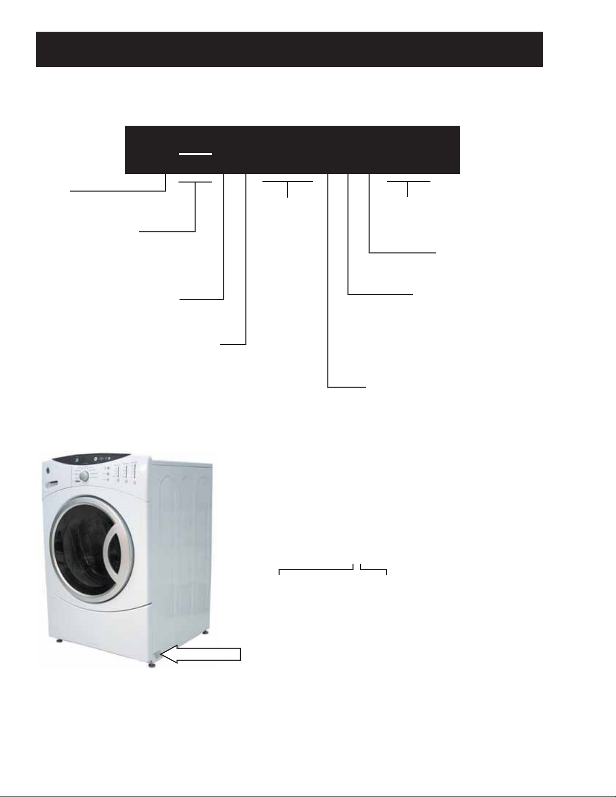
Nomenclature
The nomenclature tag is lo cat ed on
the bottom front corner on the right
side of the cabinet.
Note: The technical sheet is located
behind the control panel.
A - JAN 2005 - H
D - FEB 2004 - G
F - MAR 2003 - F
G - APR 2002 - D
H - MAY 2001 - A
L - JUN 2000 - Z
M - JUL 1999 - V
R - AUG 1998 - T
S - SEP 1997 - S
T - OCT 1996 - R
V - NOV 1995 - M
Z - DEC 1994 - L
– 4 –
The letter des ig nat ing
the year re peats every
12 years.
Example:
T - 1974
T - 1986
T - 1998
Page 5
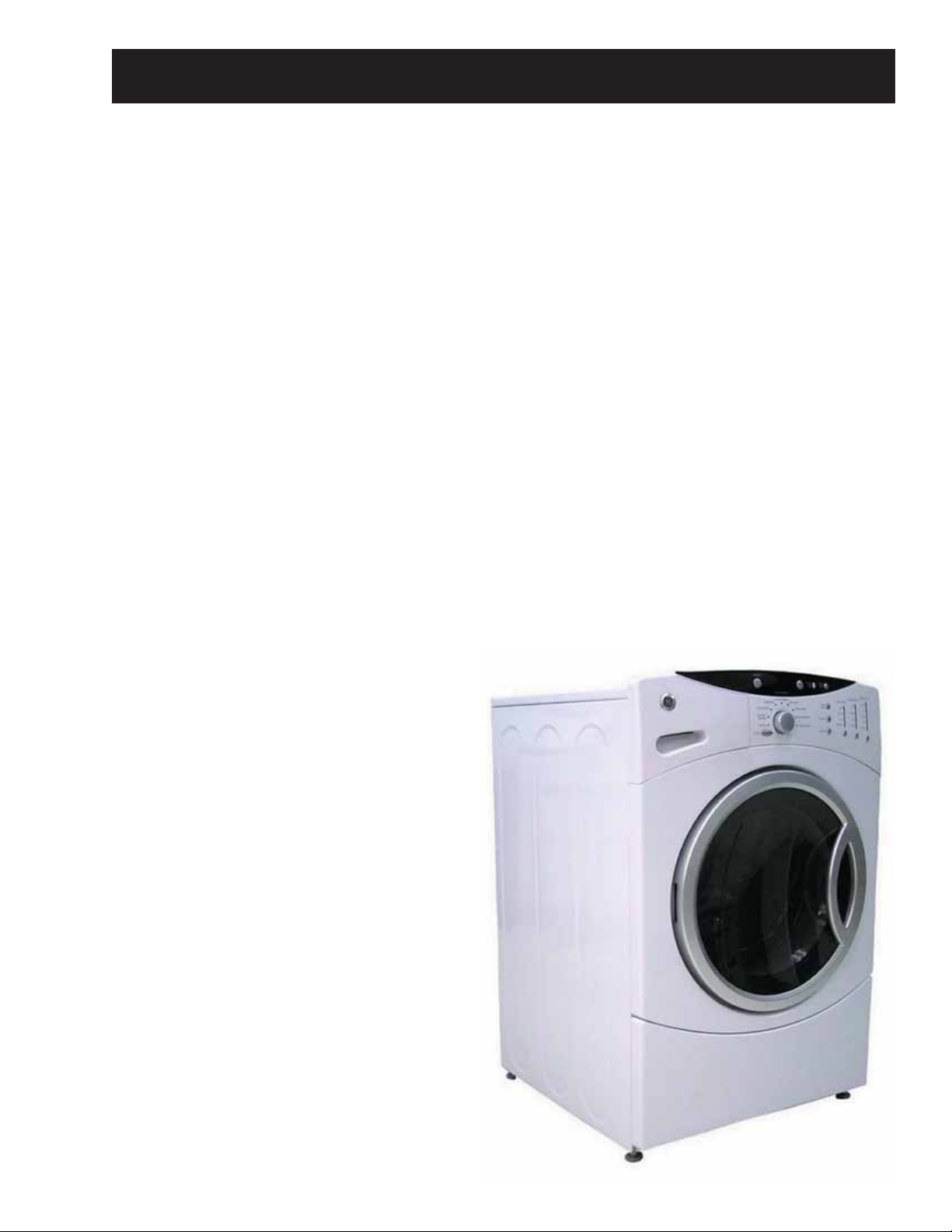
Introduction
The new GE Front Load Washer has the following features:
Energy Star Qualifi cation assures less energy waste and lower utility bills.
•
10 wash cycles include a variety of fabric-specifi c settings, from Extra-Heavy Cottons to Easy-Care
•
Colors.
My Cycle selection saves a favorite cycle for future use.
•
Dispenser adds diluted detergent, bleach, and fabric softener at the correct time during the wash or rinse
•
cycles.
A nozzle sprays water on the inner door glass to reduce detergent and mineral buildup.
•
End-Of-Cycle Signal alerts user when the cycle is done, saving time between loads. Signal volume can be
•
adjusted.
Overfl ow protection activates the drain pump whenever water reaches overfl ow level.
•
Service test mode built-in. Specifi c washer components can be operated. Error codes are recorded and
•
accessible on the control panel's 7-segment display.
Two piece plastic outer tub is formed from tough, lightweight polypropylene.
•
The wash tub is constructed of durable stainless steel.
•
Two suspension springs and four dampers provide maximum off-balance load protection with minimal
•
vibration transfer to the fl oor.
Intricate door lock keeps the door locked
•
during operation.
Blackout protection. Restoring power resumes
•
cycle where it was interrupted. Eliminating
restarting entire wash cycle.
Flush door handle.
•
UV stabilizers are utilized on the control panel,
•
top cover, and door outer panel to prevent
yellowing when exposed to sunlight.
The GE dryer can be installed on top of the
•
washer. (Stacking kit supplied with washer.)
Pedestal available at additional cost. White
•
(model number SBSD227FWW) and granite
(model number SBSD227FGG).
– 5 –
Page 6
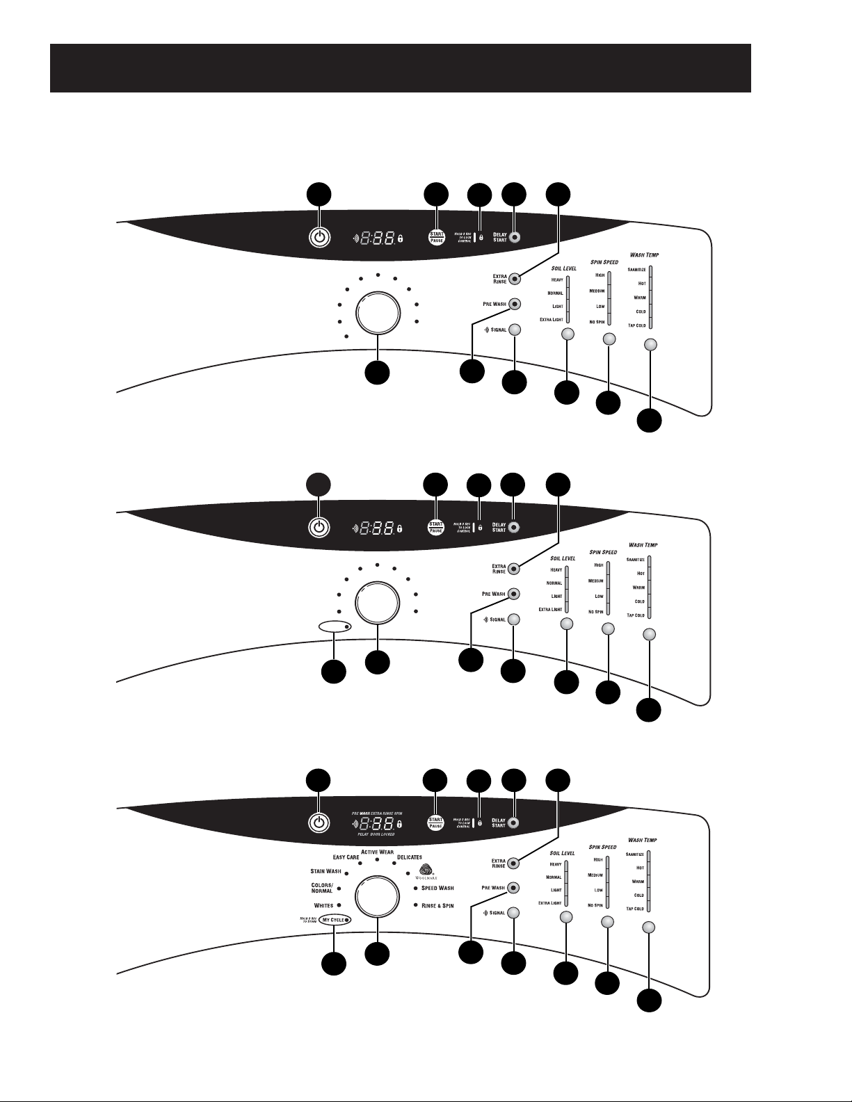
Control Features
1
5
3
4
6
2
Model WCVH6260
11
10
12
7
8
9
1
5
3
4
6
2
Model WHDVH626
11
10
12
7
8
9
4
1
5
3
4
6
2
Model WBVH6240
11
10
7
8
9
PREWASH EXTRA RINSE SPIN
DELAY DOOR LOCKED
D
ELICATES
A
S
TAIN WASH
C
N
E
ASYCARE
OLORS/
ORMAL
W
CTIVEWEAR
HITES
H
ANDWASH
S
PEEDWASH
D
R
RAIN & SPIN
INSE & SPIN
PREWASH EXTRA RINSE SPIN
DELAY DOOR LOCKED
A
CTIVEWEAR
E
ASYCARE
S
TAIN WASH
C
OLORS/
N
ORMAL
W
HITES
H
OLD
3 S
EC
MYC
YCLE
TO
S
TORE
D
ELICATES
H
ANDWASH
S
PEEDWASH
R
INSE & SPIN
– 6 –
(Continued Next Page)
Page 7
1
2
Power
Press to “wake up” the display. If the display is active, press to put the washer into standby mode.
NOTE: Pressing POWER does not disconnect the appliance from the power supply.
Wash Cycles
The wash cycles are optimized for specific types of wash loads. The chart below will help you match
the wash setting with the loads.
WHITES For heavily to lightly soiled white cottons, household linens, work and play clothes.
COLOR/NORMAL For heavy to lightly soiled colorfast cottons, household linens, work and play clothes.
STAIN WASH For heavy soiled colorfast cottons, household linens, work and play clothes.
EASY CARE For wrinkle-free and permanent press items.
(PERMA PRESS)
ACTIVE WEAR For active sports, exercise and some casual wear clothes. Fabrics include modern technology finishes and
fibers such as spandex, stretch and micro-fibers.
DELICATES For lingerie and special-care fabrics with light to normal soil. Provides gentle tumbling and soak during
wash and rinse.
HANDWASH For items labeled hand-washable with light soils. Provides gentle rocking to mimic the handwashing action.
WOOLMARK The wool wash cycle of this machine has been approved by Woolmark
®
for the washing of machine
washable Woolmark
®
products provided that the products are washed according to the instructions on the
garment label and those issued by the manufacturer of this washing machine.
MY CYCLE Press to use, create, or modify custom wash cycles.
SPEED WASH For lightly soiled items that are needed in a hurry. Cycle time is approximately 30 minutes, depending
on selected options.
DRAIN & SPIN Drain and spin at any time.
RINSE & SPIN To quickly rinse out any items at any time.
Soil Level
Changing the SOIL LEVEL increases or decreases the wash time to remove different amounts
of soil.
To change the SOIL LEVEL, press the SOIL LEVEL button until you have reached the desired
setting. You can choose between Extra Light, Light, Normal or Heavy soil.
Spin Speed
Changing the SPIN SPEED changes the final spin speed of the cycles. Always follow the fabric
manufacturer’s care label when changing the SPIN SPEED.
To change the SPIN SPEED, press the SPIN SPEED button until you have reached the desired
setting. Higher spin speeds are not available on certain cycles, such as Delicates.
Higher spin speeds remove more water from the clothes and will help reduce dry time, but may
also increase the possibility of setting wrinkles on some fabrics.
Wash Temp
Adjust to select the proper water termperature for the wash cycle. The prewash and rinse water is
always cold to help reduce energy usage and reduce setting of stains and wrinkles.
Follow the fabric manufacturer’s care label when selecting the wash temperature.
To change the wash temperature, press the WASH TEMP button until you have reached the desired
setting. The Sanitized wash temperature is not available on certain cycles, such as Delicates.
NOTE: The first 10 seconds of the wash fill is always cold. This feature assists in conditioning the fabric and
preventing stains from setting on garments.
START/PAUSE
Press to start a wash cycle. If the washer is running, pressing it once will pause the washer and
unlock the door. Press again to restart the wash cycle.
NOTE: If the washer is paused and the cycle is not restarted within 2 hours, the current wash cycle will be cancelled.
3
4
5
6
– 7 –
Page 8
Washer Features
7
8
9
10
Cycle Signal
Use the SIGNAL button to change the
volume of the end of cycle signal.
Prewash
Prewash is an extra wash before the
main wash. Use it for heavily soiled
clothes or for clothes with a care label
that recommends prewashing before
washing. Be sure to add high-efficiency
detergent, or the proper wash additive
to the prewash dispenser.
Extra Rinse
Use an extra rinse when additional
rinsing is desired to remove excess dirt
and detergent from soiled loads.
Delay Start
You can delay the start of a wash cycle
for up to 12 hours. Press the DELAY
START button to choose the number of
hours you want to delay the start of the
cycle, then press the START button. The
machine will count down and start
automatically at the correct time.
Press the button until you reach the
desired volume.
NOTE: If you forget to fully close the door, a
reminder signal will beep reminding you to do
so.
NOTE: If you open the door when the delay is
counting down, the machine will enter the
pause state. You must close the door and
press START again in order to restart the
countdown.
11
12
Lock
You can lock the controls to prevent any
selections from being made. Or you can
lock the controls after you have started a
cycle.
Children cannot accidentally start the washer
by touching pads with this option selected.
To lock the washer, press and hold the
lock button for 3 seconds. To unlock
the washer controls, press and hold the
lock button for 3 seconds.
The control lock icon on the display will
light up when it is on.
NOTE: The POWER button can still be used
when the machine is locked.
MY CYCLE
H
OLD
3 S
EC
S
TORE
MY CYCLE
TO
To save a favorite cycle, set the desired
settings and hold down the MY CYCLE
button for 3 seconds. A beep will sound
to indicate the cycle has been saved.
To use your custom cycle, press the MY
CYCLE button before washing a load.
To change the saved cycle, set the
desired settings and hold down the MY
CYCLE button for 3 seconds.
NOTE: When using MY CYCLE, wash
options cannot be modified after the cycle
has been started.
NOTE: If you change wash options with MY
CYCLE before starting the cycle, the MY
CYCLE light will turn off and you will be
returned to the base cycle.
(Continued Next Page)
– 8 –
Page 9
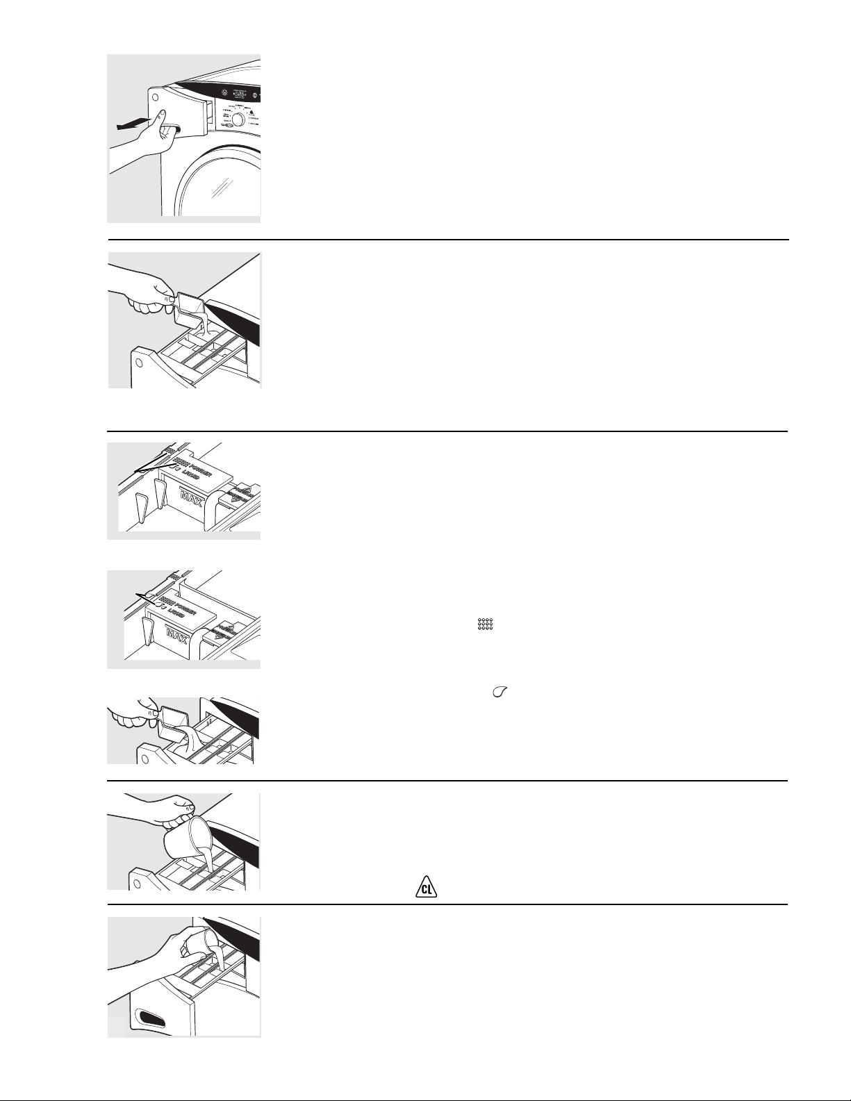
The Dispenser Drawer
Slowly open the dispenser drawer by pulling it
out until it stops.
After adding laundry products, slowly close the
dispenser drawer. Closing the drawer too quickly
could result in early dispensing of the bleach,
fabric softener or detergent.
You may see water in the bleach and fabric softener
compartments at the end of the cycle. This is a result
of the flushing/siphoning action and is part of the
normal operation of the washer.
The Liquid Bleach Compartment
If desired, measure out the recommended
amount of liquid bleach, not to exceed
1/3 cup (80 ml) and pour into the center
compartment labeled “LIQUID BLEACH”
marked with this symbol .
Do not exceed the maximum fill line. Overfilling can
cause early dispensing of the bleach which could result
in damaged clothes.
NOTE: Do not use powdered bleach in the dispenser.
The Fabric Softener Compartment
If desired, pour the recommended amount of
liquid fabric softener into the compartment
labeled “FABRIC SOFTENER.”
Use only liquid fabric softener in the
dispenser.
Dilute with water to the maximum fill line.
Do not exceed the maximum fill line. Overfilling can
cause early dispensing of the fabric softener which
could stain clothes.
NOTE: Do not pour fabric softener directly on
the wash load.
The Detergent Compartment
■ High efficiency detergent is
recommended for this washer. Use the
detergent manufacturer’s recommended
amount.
The detergent selection insert must be placed
in the detergent compartment in a specific
position according to what type of detergent
you are using.
■ Powder Detergent – Place the insert in the
rear position. The Powder Icons must
line up on center when the insert is in the
powder position.
■ Liquid Detergent – Place the insert in the
forward position. The Liquid Icons
must line up on center when the insert is
in the liquid position.
Move the insert by pulling it up and replace
it by sliding it down between either the rear
or front detergent compartment molded rails,
as desired, for powder or liquid detergent.
■ Add measured detergent to the front left
detergent compartment of the dispenser
drawer.
■ Detergent is flushed from the
dispenser at the beginning of the
wash cycle. Either powdered or liquid
detergent can be used.
■ Detergent usage may need to be adjusted
for water temperature, water hardness,
size and soil level of the load. Avoid using
too much detergent in your washer as it
can lead to oversudsing and detergent
residue being left on the clothes.
Insert in rear position for powder detergent
Insert in forward position for liquid detergent
The Prewash Compartment
■ Only use the Prewash Compartment if you
are selecting the Prewash cycle for heavily
soiled clothes. Add measured detergent or
prewash additive to the back left prewash
compartment of the dispenser drawer.
■ Detergent or prewash additive is flushed
from the dispenser in the prewash cycle
(if selected).
NOTE: Liquid detergent will drain into the washer
drum as it is added.
■ Detergent usage may need to be adjusted
for water temperature, water hardness,
size and soil level of the load. Avoid using
too much detergent in your washer as it
can lead to over sudsing and detergent
residue being left on the clothes.
8
Powder
Icons
Liquid
Icons
– 9 –
Page 10
Sorting Wash Loads
Loading the Washer
Wash drum may be fully loaded with loosely
added items. Do not wash fabrics containing
flammable materials (waxes, cleaning fluids, etc.).
To add items after washer has started,
press START/PAUSE and wait until the door is
unlatched. The washer may take up to 30 seconds
to unlock the door after pressing START/PAUSE
depending on the machine conditions. Do not
try to force open the door when it is locked. After
the door unlocks, open gently. Add items, close
the door and press START/PAUSE to restart.
Colors
Whites
Lights
Darks
Soil
Heavy
Normal
Light
Fabric
Delicates
Easy Care
Sturdy Cottons
Lint
Lint Producers
Lint Collectors
■ Combine large and small items in a load. Load large items first. Large items should not be more than half the
total wash load.
■ Washing single items is not recommended. This may cause an out-of-balance load. Add one or two similar
items.
■ Pillows and comforters should not be mixed with other items. This may cause an out-of-balance load.
Sort laundry into loads that can be washed together.
Using the Washer
Care and Cleaning
Exterior: Immediately wipe off any spills. Wipe with damp cloth. Do not hit surface with
sharp objects.
Interior: Dry around the washer door opening, flexible gasket and door glass. These areas should
always be clean to ensure a water tight seal.
Moving and Storage: Ask the service technician to remove water from drain pump and hoses.
Do not store the washer where it will be exposed to the weather. When moving the washer,
the tub should be kept stationary by using the shipping bolts removed during installation.
If these parts are not available, they can be ordered by
visiting our Website at www.GEAppliances.com or by calling 800.GE.CARES.
Long Vacations: Be sure water supply is shut off at faucets. Drain all water from hoses if weather will
be below freezing.
– 10 –
(Continued Next Page)
Page 11
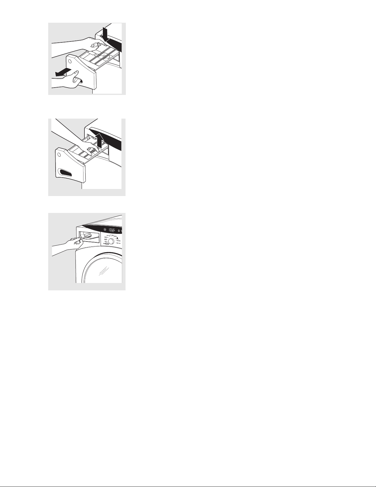
Dispenser Drawer Area: Detergent and fabric softener may build up in the
dispenser drawer. Residue should be removed once or twice a month.
■ Remove the drawer by first pulling it out until it stops. Then reach back into
the left rear corner of the drawer cavity and press down firmly on the lock
tab, pulling out the drawer.
■ Remove the inserts from the bleach and fabric softener compartments and
the detergent insert. Rinse the inserts and the drawer with hot water to
remove traces of accumulated laundry products.
■ To clean the drawer opening, use a small brush to clean the recess. Remove
all residue from the upper and lower parts of the recess.
■ Return inserts to the proper compartments. Replace the dispenser drawer.
Lock tab is visible only after drawer
has been pulled out
– 11 –
Page 12
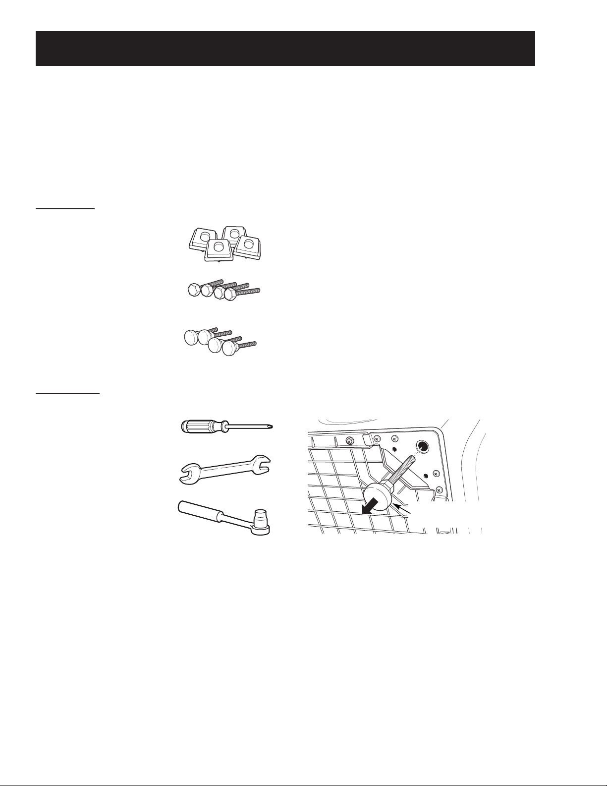
Pedestal Installation (Washer and Dryer)
Back out and remove
all 4 leveling legs
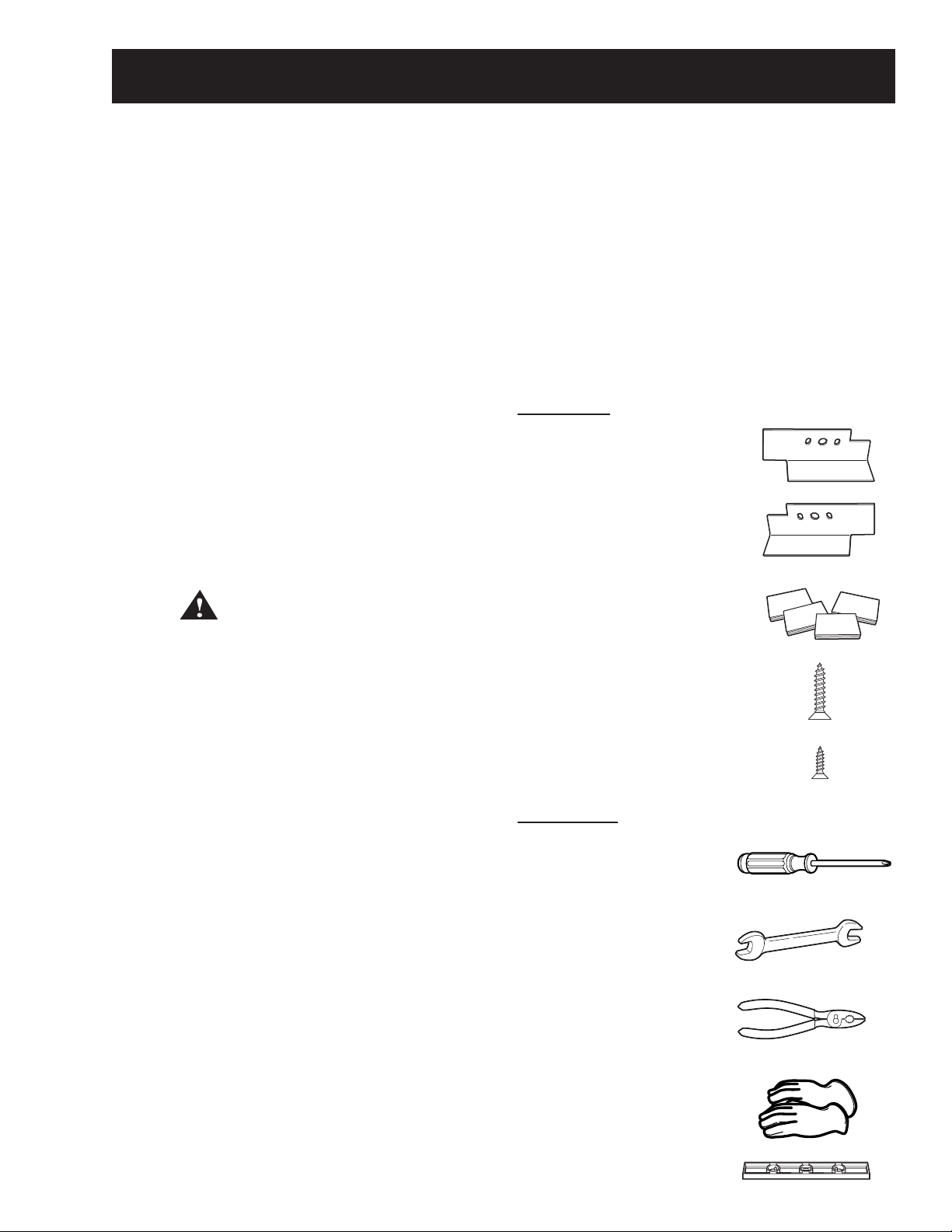
Optional 12-in. high storage drawer pedestals with
dividers are available to provide convenience and
extra storage space for detergent, dryer sheets and
other cleaning supplies. The pedestal installation kit
includes 4 support pads, 4 mounting screws, and 4
leveling legs with locknuts.
Kit Contents
4 Support Pads
4 Mounting Screws
4 Leveling Legs
with Locknuts
Tools Needed
WARNING: Due to the size and weight of the
washer or dryer, and to reduce the risk of personal
injury or damage, 2 people are required for proper
installation.
Note:
DO NOT remove washer shipping bolts prior to
•
pedestal installation. Shipping bolts MUST be
reinstalled, if previously removed.
Care should always be taken when laying
•
the washer or dryer on its side to prevent
component damage.
Do not lay washer or dryer on its back. Use a
•
pad or protective surface when laying washer or
dryer on its side.
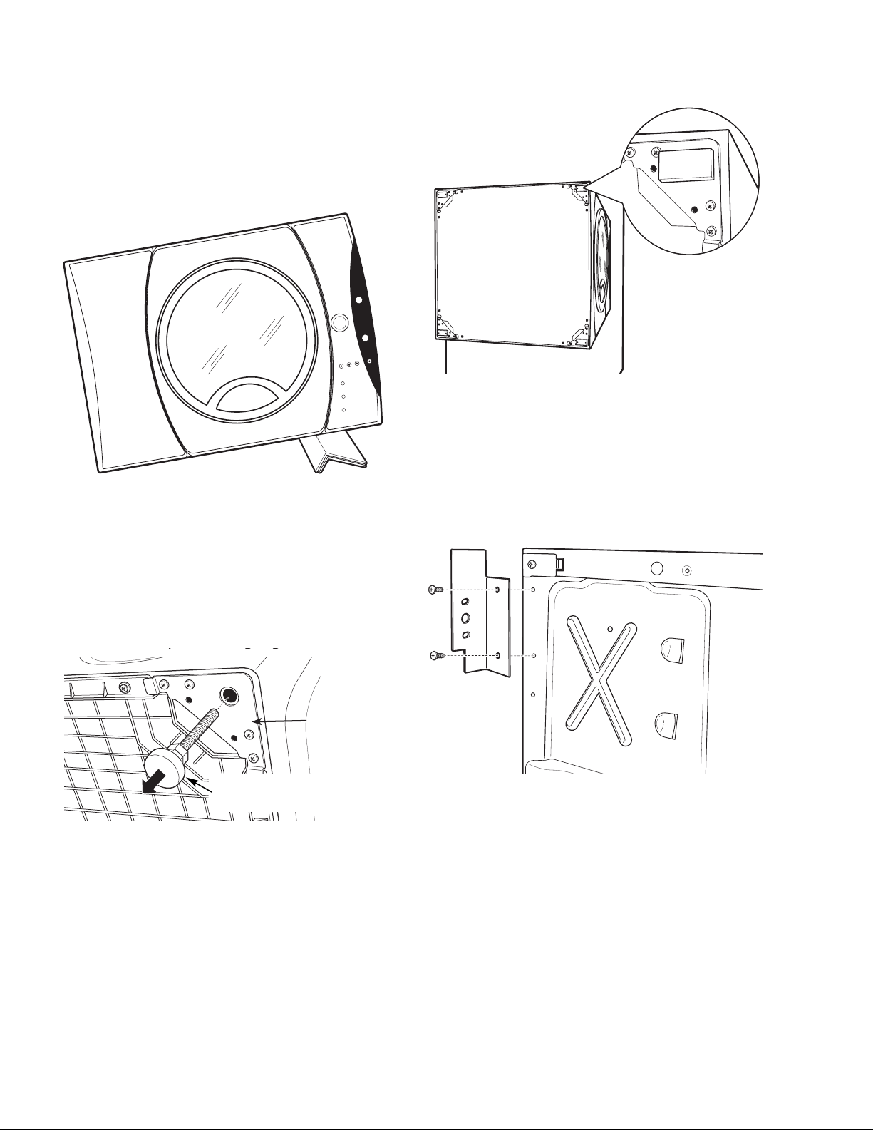
To install the pedestal:
Lay the washer or dryer on its side.
1.
Remove the 4 leveling legs.
2.
Phillips-head Screwdriver
9/16" Open End Wrench
or Adjustable Wrench
8-mm Socket Wrench
– 12 –
(Continued Next Page)
Page 13
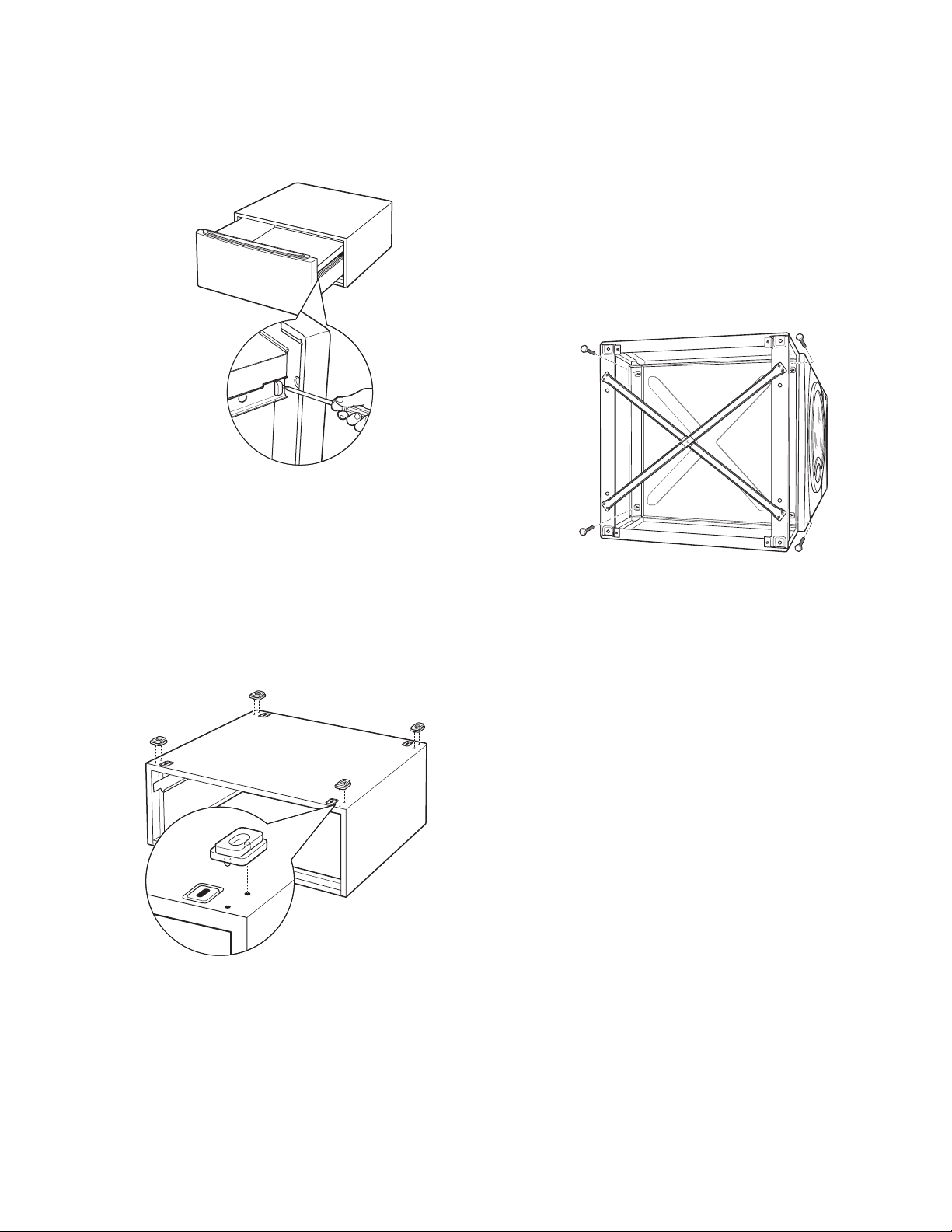
Pull the drawer out to its stop position.
3.
Remove the screws from the drawer slides.
4.
Slide the drawer out of the base and set it aside.
5.
Place the pedestal against the bottom of the
7.
washer or dryer. Ensure that the drawer front is
at the front of the washer or dryer.
Align the holes in the pedestal with the holes in
8.
the bottom of the washer or dryer base.
Use a Phillips-head screwdriver to install the 4
9.
(8-mm) bolts through the pedestal and into the
unit. DO NOT tighten the bolts.
Align the pedestal with the unit. Use an 8-mm
10.
socket wrench to securely tighten the bolts.
Note: The support pads should be installed on the
dryer only. DO NOT INSTALL THE PADS ON THE
WASHER PEDESTAL.
Install a support pad at each top corner of the
6.
pedestal. Ensure both protrusions on each pad
are inserted in the holes on top of the pedestal.
– 13 –
(Continued Next Page)
Page 14
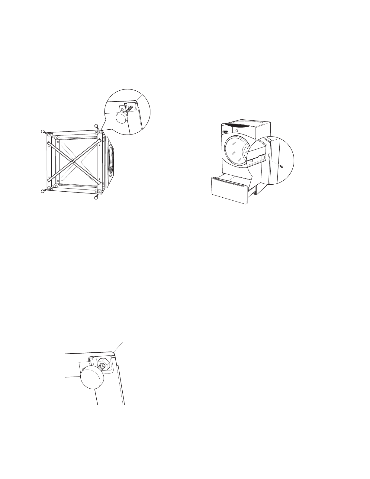
Screw locknuts onto the supplied leveling legs.
11.
Turn the nuts toward the bottom and against
the rubber part of the leg.
Install the leveling legs, with locknuts, in each
12.
corner support. Screw the legs all the way into
the pedestal. Do not tighten.
Ensure that the slides are closed, then slide the
16.
drawer into the opening.
Align the drawer supports to the slides on each
17.
side.
Reinstall the original screws in each drawer
18.
slide.
Note: The drawer should slide smoothly when you
push it closed.
Stand the washer or dryer upright. Move it close
13.
to its fi nal location.
Make sure that the washer or dryer is level by
14.
placing a spirit level on top. Check side to side
and front to back.
Use an open end or adjustable wrench to adjust
15.
the legs in or out. Tighten the locknuts against
the bottom of the pedestal.
Note: To minimize vibration, the locknuts must be
tight.
Remove the 4 shipping screws from the back of
19.
the washer.
Note: Refer to the washer or dryer installation
instructions to complete the installation.
– 14 –
Page 15
Stacking Instructions
The GE front load washer is designed to allow
certain models of the GE dryer to be placed on top
(stacking). Dryer models that currently qualify for
stacking are:
•
DBVH512
•
DCVH515
•
DHDVH52
The parts and instructions necessary to convert the
separate units to a stack unit are included with the
washer installation parts.
Note: The stacking parts and instructions are NOT
included with the GE dryers listed above, but can be
ordered separately. (Part # WE25X10018)
Minimum vertical space from fl oor to overhead
•
cabinets, ceiling, etc. is 43 inches without
pedestal, 55 inches with pedestal, and 84
inches stacked. Closet doors must be louvered
or otherwise ventilated and must contain a
minimum of 120 square inches of open area,
equally distributed.
The dryer MUST be vented to the outdoors.
•
(Refer to dryer installation instructions for
details.)
Kit Contents
Right Bracket
Note: Reverse the dryer door swing (if desired)
BEFORE stacking. The washer door swing is NOT
reversible.
WARNING!
• Make sure the dryer is unplugged.
• More than 2 people are recommended to safely
lift the dryer into position.
• Avoid damage to the existing utility services.
DO NOT place the washer on top of the dryer.
•
Stacking of a gas dryer is NOT permitted in a
•
mobile home or a manufactured home.
Location Requirements
When installed in a location other than an alcove
or closet, the minimal clearances to combustible
surfaces and for air opening are: 0 inches on both
sides, and 1 inch at the rear.
Left Bracket
4 Rubber Pads
4 #12 x 1" Screws
4 #8 x ½" Screws
Tools Needed
Phillips Screwdriver
Open End Wrench
Note: If your dryer is approved for installation in an
alcove or a closet, it will be stated on a label on the
back.
When installed in an alcove or closet:
Minimum clearance between dryer cabinet
•
and adjacent walls or other surfaces is 0 inches
either side, and 3 inches front and rear.
Pliers
Gloves
Level
(Continued Next Page)
– 15 –
Page 16
To stack the dryer:
y gg
Back out and remove
all 4 leveling legs
Caution: Do not lay dryer on its back. Use the
packing material or a protective surface when
laying dryer on its side.
Carefully lay the dryer on its side. 1.
Remove the adhesive backing and fi rmly place
3.
the 4 rubber pads over the leg brackets.
Align the holes in the left bracket with the holes
4.
in the bottom left corner of the dryer. Attach
the bracket using 2 (#12 x 1-in.) Phillips-head
screws.
Use an open end wrench or pliers to remove the
2.
4 dryer leveling legs from the leg brackets.
Leg bracket
Align the holes in the right bracket with the holes
5.
in the bottom right corner of the dryer. Attach
the bracket using 2 (#12 x 1-in.) Phillips-head
screws.
– 16 –
(Continued Next Page)
Page 17
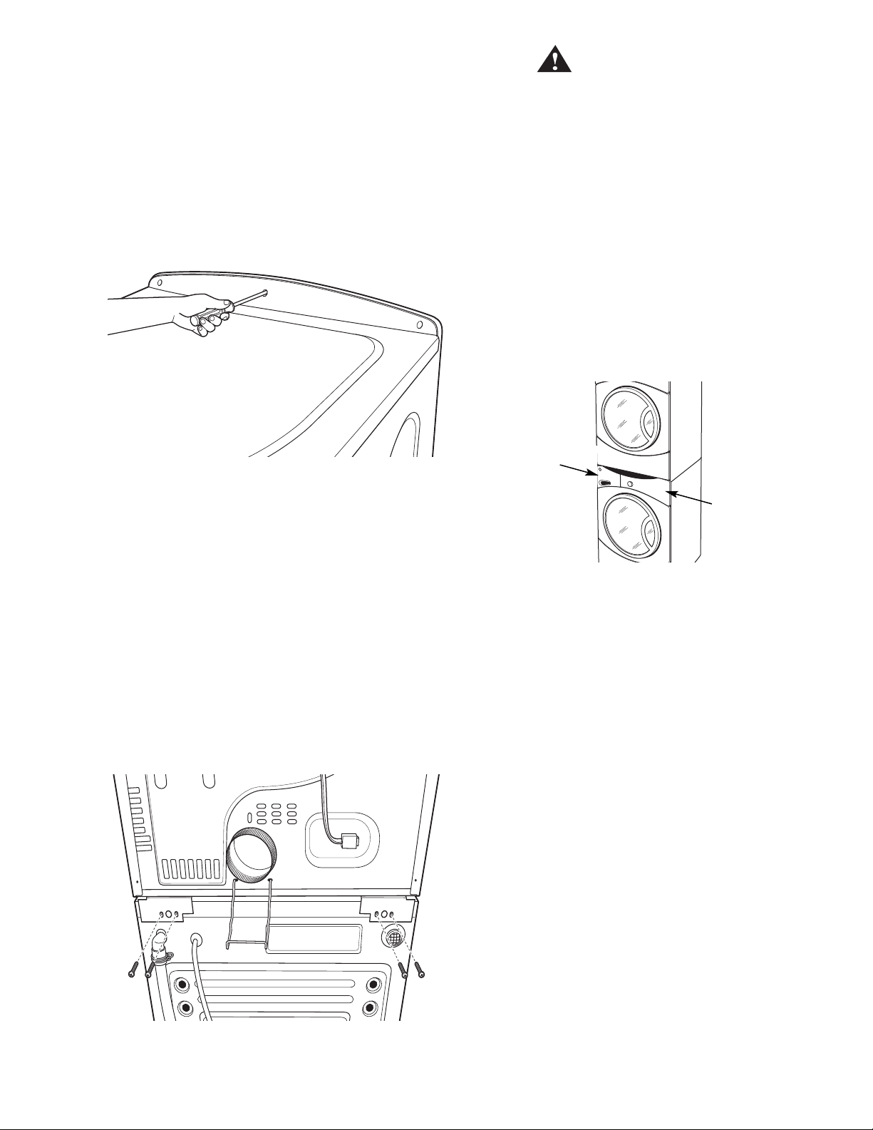
Set the dryer upright using packing material or a
Place hands here
Place hands here
6.
protective surface that ensures the brackets do
not damage the fl oor.
Place and level the washer in the approximate
7.
location. (Refer to washer installation
instructions for details.)
Remove the 3 Phillips-head screws that attach
8.
the top cover, then pull the cover rearward.
WARNING!
Do not push on the dryer after it is stacked on the
washer. Pushing on the dryer may result in pinched
fi ngers.
Caution: Use felt pads or other sliding device to
assist moving and to protect fl ooring.
Note: Ensure that the washer and the dryer are
in compliance with their respective installation
instructions.
Carefully slide or walk the stacked washer and
11.
dryer into place.
Caution: Protect the washer control panel with
cardboard or other protection to prevent damage
caused by contact with the dryer brackets.
Lift the dryer high enough to clear the washer
9.
control panel and place the dryer on top of the
washer.
Align the holes in the brackets with the holes
10.
in the back of the washer. Attach the brackets
to the washer using 4 (#8 x ½-in.) Phillips-head
screws.
– 17 –
Page 18

Operation Overview
Basic Wash Cycle
Note: See Component Locator Views for identifi cation
and location of washer components.
After a load is placed in the wash basket, the user
opens the dispenser drawer and positions the
detergent selector for the type of detergent to be
used.
Detergent is added to the detergent compartment.
Detergent is added to the prewash compartment
only if prewash cycle is selected.
Note: The prewash compartment is only fl ushed
with water when the PRE WASH option is selected
on the control.
If desired, add a measured amount (1/3 cup or less)
of bleach into the bleach compartment.
If desired, add the recommended amount of fabric
softener in the fabric softener compartment and
dilute with water to the maximum fi ll line.
Select the SPIN SPEED to change the fi nal spin speed
of the cycles. Follow the fabric manufacturer's care
label when selecting spin speed.
Select the WASH TEMP to adjust the proper water
temperature for the wash cycle. Follow the fabric
manufacturer's care label when selecting wash
temperature.
Press START/PAUSE to start the wash cycle. Each
time the washer starts, a wake up routine is
initiated:
1.
The door locks.
2.
The wash basket briefl y tumbles in both
directions.
3.
The door unlocks.
4.
The door locks.
5.
The fi ll cycle begins.
Water Fill
After adding laundry products, slowly close the
dispenser drawer.
The user presses the POWER button to activate the
display. If the display is active, press POWER button
to put washer into standby mode.
Rotate the cycle knob to the desired wash setting.
When selecting Whites, Colors/Normal, Active Wear,
or Delicates cycles, the following control default
settings can be changed:
EXTRA RINSE
•
PRE WASH
•
SOIL LEVEL
•
SPIN SPEED
•
WASH TEMP
•
Select EXTRA RINSE and PRE WASH options. Use the
SIGNAL button to change the volume level of the
end of cycle signal.
The washer automatically fi lls before tumbling, and
maintains the proper fi ll level using a programmed
adaptive fi ll. The machine will not tumble while
fi lling.
Wash Water Temperature
The fi rst 10 seconds of fi ll is tap cold water only. If
needed, the control board will cycle the water valves
(water tempering) to achieve the target wash water
temperature selected. Water tempering only occurs
during the main wash cycle.
Tap Cold:
Cold water valve energized.
•
Tap cold never involves water tempering.
•
Water temperature determined by supply
•
temperature.
All fi lls except main wash are tap cold.
•
Select the SOIL LEVEL to increase or decrease wash
time needed to remove different amounts of soil.
– 18 –
(Continued Next Page)
Page 19

Cold:
Cold water valve energized.
•
Cold selection is tempered by default for main
•
wash.
Cold can be tempered by cycling of hot water
•
valve to achieve target temperature of 80°F
(27°C).
The available selection of spin speeds is controlled
by cycle selection.
For example:
Spin Speed Whites Delicates
High 1000 rpm 525 rpm
Medium 750 rpm 450 rpm
Low 525 rpm 350 rpm
Warm:
Hot and cold water valves energized.
•
Warm can be tempered by cycling of hot and
•
cold valves to achieve target temperature of
105°F (40.5°C).
Warm selection is tempered by default for main
•
wash.
Hot:
Hot water valve energized.
•
Hot can be tempered by cycling of cold water
•
valve to achieve target temperature of 120°F
(49°C).
Hot selection is tempered by default main wash.
•
Sanitize:
Hot water valve energized.
•
Selecting a spin speed modifi es fi nal spin only
and must be made before fi nal spin takes place.
The length of time required to achieve spin rpm is
monitored by the control via the motor sensor. With
a balanced load, if the selected spin speed cannot
be achieved, the washer will default to highest
speed attained and will increase spin time.
Off-balance load protection is programmed into
the control board. If speed is not achieved, the spin
routine halts. The washer tumbles to redistribute the
load and attempts to spin again. After 5 attempts,
if an off-balance load remains detected, spin speed
defaults to the highest speed attained or 90 rpm
(whichever is greater) for the remainder of the cycle.
Sanitize can be tempered by cycling of cold
•
water valve, or heater operation, to achieve
target temperature of 160°F (71°C).
Tumble Wash
Wash routines are programmed by cycle. The only
adjustment to the tumble routine is through cycle
selection.
The basket rotates clockwise for a predetermined
period of time at a predetermined speed. The
basket pauses for a predetermined period of
time. The basket rotates counterclockwise for a
predetermined period of time at a predetermined
speed. The length of tumble wash time is adaptive
to the soil level programmed into the machine at the
start of the cycle.
Spin
The spin is designed to extract as much water and
detergent as possible without harming fabrics.
Speeds can be as slow as 90 rpm (out of balance
default) to as high as 1000 rpm.
– 19 –
Page 20

Top View
Water Valve Outlet Hose
Component Locator Views
3-Way Pipe
Dispenser Inlet Hose
Dispenser
Assembly
Water Valve
Line Filter
Nozzle Hose
Dispenser Vent Hose
Thermistor
Water Level Control
Heating Element
Front View
Damper
Inverter
Motor
Tub Drain Hose
– 20 –
Pump Outlet Hose
Pump
(Continued Next Page)
Page 21

Component Locator Views (Con't)
Tub Drive Pulley
Belt
Motor
Dispenser Drawer
– 21 –
Page 22

Control Board
Control and Inverter Board Connections
P4
P5
P3
P2
P6
P8
P7
P9
P1 Door lock and line fi lter
P2 Door lock, heater, 120 VAC output to inverter, dispenser motor, hot and cold water valves
P3 WCL main level and overfl ow switches, heater, neutral output to inverter, and door lock
P4 Dispenser switch
P5 Hot and cold water valves and dispenser motor
P6 WCL foam switch and door switch
P7 Thermistor
P8 WCL overfl ow switch, pump, door lock, and unlock solenoids
P9 Motor sensor and DC voltage output to inverter
Inverter Board
P1
DC Input Voltage
from Control Board
Output To Motor
120 VAC Input From Control Board
– 22 –
Page 23

Washer Components
Top Panel
WARNING: Sharp edges may be exposed when
servicing washer. Use caution to avoid injury and
wear Kevlar gloves or equivalent protection.
Note: Combined Phillips-head/square-drive recess
screws can be utilized throughout this appliance.
Either Phillips or square-drive screwdrivers can be
used to extract or install these screws.
Removal of the top panel provides access to the
control panel, dispenser, water valve, water level
control, and line fi lter. The top panel is held in place
by a top cover and 3 screws on the back.
To remove the top panel:
Remove the 3 Phillips-head screws that attach
1.
the top cover, then pull the cover rearward.
Note: It may be helpful to place a putty knife along
the top seam between the cover and control panel,
then tap lightly rearward.
Service Panel
Removal of the service panel provides access to
the pump cleanout, pump, tub drain hose, heater
assembly, inverter, wire junction box, front dampers,
and the door lock release ring.
To remove the service panel:
Remove the 3 Phillips-head screws that hold the
1.
service panel to the cabinet.
Pull the service panel down.
2.
Remove the 3 (7-mm) hex-head screws that
2.
attach the rear of the top panel to the cabinet.
Rear View
Top Cover Screws
Top Panel Screws
Slide the top panel rearward 1 inch then lift the
3.
panel.
– 23 –
Page 24

Control Panel
The control panel is held in place with 5 Phillipshead screws and 5 tabs.
To remove the control panel assembly:
Remove the top panel. (See Top Panel.)
1.
Pull the dispenser out to the stop position. Press
2.
down on the lock tab. Pull the dispenser out.
Lock Tab
From inside the cabinet, lift and push forward to
5.
release the bottom tab from the front bracket.
Bottom Tab
Side Tab
Remove the single Phillips-head screw from the
3.
control panel dispenser recess.
Lift the top edge of the panel to disengage the 3
6.
tabs that hold the top of the panel in place.
Remove the 4 Phillips-head screws that attach
4.
the top of the control panel to the control panel
cover.
Rear View
7.
8.
– 24 –
Push the control panel towards the left, then
release the side tab.
Disconnect the 9 wire harnesses from the
control panel.
Page 25

Control Board
The control board is mounted in a housing that is attached to the inside of the control panel. The control
board and housing are replaced as an assembly. The control board assembly is held in place by 4 Phillipshead screws and 3 tabs. The control board is programmed to recognize 6 modes of operation.
Mode Name Description
Idle No cycle is selected. All LEDs, 7-segment display on front panel, load selections and
options are off. The door is unlocked. The control board is ready to take input from
user.
Standby A cycle is selected with the appropriate load selections and options. LEDs and 7-segment
display on front panel are on. The door is unlocked. The control board is ready to take
user input to either modify cycle selections or start a selected cycle.
Run The control board is executing the currently selected cycle. The door is locked.
Pause The control is stopped by user during the execution of a cycle. LEDs and 7-segment
display on front panel stay on, all loads are turned off. The door is unlocked. The control
board is ready to take user input to either modify, resume, or cancel the cycle.
End of Cycle A cycle is completed. LEDs and 7-segment display on front panel stay on, all loads are
turned off. The door is unlocked. The control board remains in this mode until the door
is opened or after 2 hours have passed.
Fault The control board detected a critical failure condition. The 7-segment display shows the
fault code, all loads are turned off. The fault code can only be removed in the service
test mode. (See Service Test Mode.)
Operation of the control board can be checked by using the service test mode. (See
Specifi c failures associated with the control board can initiate error codes E52, E57, E58, E70, and E71. (See
Service Test Mode.)
Service Test Mode.)
– 25 –
(Continued Next Page)
Page 26

To remove the control board assembly:
Remove the control panel. (See Control Panel.)
1.
Pull the cycle knob off.
2.
Remove the 4 Phillips-head screws that hold the
3.
control board assembly to the control panel.
Release the 3 tabs at the bottom of the control
4.
panel.
Ta bs
Remove the control board assembly from the
5.
control panel.
Remove the cycle selection buttons.
6.
Note:
The replacement control board will always enter
•
into test mode t01 on initial power-up.
If replacing the control board, the washer will
•
not function until the replacement control board
has been programmed.
Door Lock
The door lock contains a door switch and solenoid
operated locking and unlocking mechanism. A
release ring, located at the bottom, allows for
manual unlocking of the door.
The door locks when a cycle is entered (Wake-up
routine) and during every cycle. The door unlocks at
the completion of a cycle.
The door will not open when:
The foam switch is open
•
Water temperature is above 130°F (54°C)
•
Wash basket is rotating
•
Specifi c failures associated with the door lock can
initiate error codes E60 thru E64. (See Service Test
Mode.)
The door lock is held to the front panel with 3
Phillips-head screws. The door lock is accessed from
the front of the washer when the right side of the
gasket is partially pulled back.
To remove the door lock :
Remove the 3 Phillips-head screws that hold the
1.
door lock to the front panel.
Programming the Control Board
To program the replacement control board:
Reconnect power to the washer. (The display
1.
will now show "---", which means no model has
been selected.)
Rotate the cycle knob until the correct model
2.
number is displayed:
Select 1 for model WHDVH626F
•
Select 2 for model WCVH6260F
•
Select 3 for model WBVH6240F
•
Press and hold the Start key for 3 seconds (or
3.
until a second beep is sounded).
Press the Power key to reset the control.
4.
Note: If an error is made in programming the
control, enter test mode and select t01. Then repeat
steps 2 thru 4.
– 26 –
(Continued Next Page)
Page 27

Use a long-nose pliers to grasp the wire loop at
2.
the spring location and expand it to clear the
gasket.
Note: The door latch is solenoid activated. It can
remain locked after power is removed.
To manually unlock door:
1.
Disconnect the washer from electrical supply.
WARNING: To avoid injury, ensure all mechanical
movement has stopped.
Remove the spring and wire from the gasket.
3.
Pull the right side of the gasket away from the
4.
front panel.
Pull the door lock to the opening and remove the
5.
3 wire harnesses.
2.
Remove the service panel. (See
Reach behind and up the right side of the front
3.
Service Panel.)
panel, pull the release ring down, then open the
door.
Door Strike
To remove the door strike:
Open the door.
1.
Remove the 2 Phillips-head screws that hold the
2.
door strike to the door frame cover.
Door Strike
Release Ring
Door Frame Cover
3.
Remove the door strike.
Note: The door strike position on the door can be
1
horizontally adjusted
/8-inch. Adjust position of the
door strike for best door closure.
– 27 –
Page 28

Front Panel
Line Filter
The front panel is hung on 2 hooks attached to
the cabinet and held in place with 4 Phillips-head
screws. A gasket provides a watertight seal between
the front panel and outer tub. The front of the gasket
is secured to the front panel fl ange by a spring and
wire located in the fold of the gasket. The door lock
and wiring is attached to the front panel.
To remove the front panel:
Remove the control panel. (See Control Panel.)
1.
Remove the service panel. (See Service Panel.)
2.
Open the door. Remove the 3 Phillips-head
3.
screws that hold the door lock to the front panel.
(See Door Lock.)
Remove the spring and wire from the gasket.
4.
(See Door Lock.)
Position the gasket behind the front panel door
5.
opening. Close the door.
Remove the 4 Phillips-head screws that attach
6.
the front panel to the cabinet.
The line fi lter helps to smooth out any fl uctuations in
voltage, protecting the control board and providing
more reliable operation. The line fi lter is installed on
the interior side of the rear panel, and is located left
of the water valve.
To check the line fi lter, look for the outer surface
to be burnt by heat or a power surge. The fi lter
resistance should be approximately 0 Ω between
the black (top) wire terminals and 0 Ω between the
white (bottom) wire terminals.
To remove the line fi lter:
Remove the single black (top) and single white
1.
(bottom) wires.
Disconnect the wire harness by pressing the tab
2.
and pulling outward.
Press the locking tab and remove the ground
3.
wire.
Lift up then remove the front panel from the 2
7.
hooks.
4.
– 28 –
Remove the 2 (7-mm) hex-head screws that hold
the fi lter to the frame.
Move the fi lter to the right. 5.
Page 29

Dispenser Assembly
The dispenser assembly provides automatic
dispensing of detergent, bleach, and fabric softener
as long as the user fi lls the compartments prior to
starting the washer.
Caution: When testing the dispenser motor, DO
NOT remove the wiring harness from the dispenser
motor unless replacing the motor assembly. The
motor assembly has a special locking connector
and the wiring harness will not stay reconnected if
removed and reinstalled on the same motor.
The products added to the dispenser are diluted
with water before they are dispensed into the wash
tub. This is accomplished by a water diverter that
sprays a controlled jet of water into the proper
compartment at the correct time. The water diverter
movement is provided by a motor driven cam
located on the dispenser tank. The diverter motor
and water valve are operated by the control board.
At the start of a cycle, after the wake-up routine
is completed, the dispenser always moves into
position before fi ll takes place.
Motor Driven Cam
Water Diverter
To remove the dispenser assembly:
1.
Remove the top and control panels. (See
Control Panels.)
Remove the gasket from the front panel. (See
2.
Gasket.)
Remove the gasket inlet hose from the clip
3.
Top and
attached to the dispenser.
Remove the inlet and the dispenser vent hoses
4.
from the dispenser:
Note: The inlet and the dispenser vent hoses are
diffi cult to remove.
a. Squeeze each clamp and slide it back.
b. Carefully break each hose loose by inserting
a small fl at-blade screwdriver under the
hose to break the seal.
c. Remove the hoses.
Dispenser Tank
Position Dispenser Function
1 Pre Wash
2 Wash
3 Bleach
4 Fabric Softener
Operation of the dispenser can be checked by using
service test mode t12. (See
Service Test Mode.)
Specifi c failures associated with the dispenser can
initiate error codes E38, E39, and E62. (See Service
Test Mode.)
Note: An inlet tube is placed between the inlet hose
and the dispenser tank. The inlet tube provides
proper water pressure to the dispenser and nozzle.
When removing the inlet hose, the inlet tube may
remain in the hose. Ensure the inlet tube is fully
inserted into the tank inlet upon reassembly.
– 29 –
(Continued Next Page)
Page 30

Inlet Hose
Inlet Tube
Tank Inlet
Gasket
Inlet
Hose
Caution: A small retainer for the dispenser motor
wiring, located underneath the unused inlet, is
fragile. To avoid breakage, use minimal outward
pressure when releasing wiring.
Release the dispenser motor wiring from the
5.
retainer.
Remove the 2 Phillips-head screws that attach
6.
the motor and clip to the dispenser tank. Place
the motor and clip aside.
Motor
Unused Inlet
Clip
Dispenser Vent Hose
Note: Reinstall dispenser vent hose with notch
aligned on dispenser tank and ensure seam remains
aligned with the pointer on the outer tub.
Notch
Seam
Clip
Disengage the 2 plastic wire retainers from the
7.
front bracket by pressing the lock tabs inward.
Pointer
– 30 –
(Continued Next Page)
Page 31

Remove the 2 Phillips-head screws that hold the
8.
dispenser to the front bracket.
Remove the 8 Phillips-head screws that attach
9.
the control rear cover and the front bracket.
Remove the dispenser from the cabinet.
11.
Caution: The water inlet pipe is fi rmly attached to
the dispenser tank. Care must be taken to avoid
damage to the dispenser tank.
Remove the water inlet pipe by twisting and
12.
pulling outward.
Screw Locations
Raise the control rear cover and the front
10.
bracket vertically and set them towards the top
rear of washer.
Inlet Pipe Seal
Water Inlet Pipe
– 31 –
(Continued Next Page)
Page 32

Note: The inlet pipe seal is diffi cult to install, place a
small amount of liquid soap on the seal. Install the
inlet pipe in alignment with the indentation at the
bottom of the dispenser tank.
Bottom of Tank
Dispenser Motor
The dispenser is operated by a 120 VAC, 60 HZ.
motor. The dispenser motor receives commands
from the control board and controls dispenser
operation.
Operation of the dispenser motor can be checked
by using the Service Test Mode t12. (See Service Test
Mode.)
Specifi c failures associated with the dispenser
motor can initiate error codes E38, E39, and E62.
(See Service Test Mode.)
To remove the dispenser motor:
Indentation
Water Inlet Pipe
Note: Ensure the dispenser guide pin is inserted into
the slot in the side of the cabinet left side top brace.
Access the dispenser assembly. (See Dispenser
Assembly.)
Caution: Lock tabs on dispenser motor wiring
harnesses are fragile. Tab breakage can occur if
excessive release pressure is applied.
Disconnect the 2 wire harnesses from the
1.
dispenser motor.
Note: It can be helpful to insert a small fl atbladed screwdriver (as shown) to remove the wire
harnesses.
Harness Removal
Slot
Pin
2.
3.
– 32 –
Remove the 2 Phillips-head screws that attach
the motor and gasket inlet hose clip to the
dispenser tank. (See
Dispenser Assembly.)
Lift dispenser motor vertically from dispenser
tank.
Page 33

Water Level Control
Water Level Control Operation
The water level control is installed on the cabinet
right side top brace. The water level control is
connected by a hose to an air chamber attached to
the bottom of the outer tub. The water level control
consists of 3 internal switches that monitor 4 water
level conditions.
When the water level rises in the outer tub, air is
•
trapped in the air chamber.
As the water level rises, the air pressure in the
•
air chamber increases.
The increased pressure operates the 3 internal
•
switches.
The washer has overfl ow protection and will
•
automatically pump out regardless of whether
the washer is on or off, as long as the unit is
plugged in. This action supersedes all other
commands.
The 3 internal switches are identifi ed as foam,
•
main, and overfl ow. The 4 water level conditions
monitored are empty, foam, main, and overfl ow.
When the machine is empty, the foam switch is
closed and the motor circuit is disabled. When the
main wash cycle is activated, the fi ll valve begins
operating. The machine fi lls to the foam water
level, the foam switch opens, and tumble begins.
Water temperature is read by the thermistor and
fi ll valve percentage of operation (water tempering)
is calculated for the main wash. When calculated,
and/or when the load absorbs water, the tumbling
will pause. Fill will continue until the main water level
is reached (Adaptive fi ll), the main switch closes, and
main wash tumbling begins.
Water Levels
The foam water level is approximately 2 1/2 inches
below the door opening and approximately 3/4 inch
deep at the bottom center of the wash basket.
Foam Water Level
Level Switch Position
Foam Main Overfl ow
Empty Closed Open Open
Foam Open Open Open
Main Open Closed Open
Overfl ow Open Closed Closed
Foam
Main
Overfl ow
1
The main water level is approximately 1
/2 inches
below the door opening and approximately 2 1/8
inches deep at the bottom center of the wash
basket.
Main Water Level
Water Level Control
– 33 –
(Continued Next Page)
Page 34

The overfl ow water level is approximately 6
1
/2 inches
above the door opening. Overfl ow protection will
occur at this water level.
Overfl ow Water Level
To remove the water level control:
Remove the top panel. (See Top Panel.)
1.
Press down the single tab, then disconnect each
2.
of the 2 wire harnesses.
Remove the pressure tube.
3.
Note: The pressure tube is diffi cult to remove.
a. Squeeze the clamp and slide it back.
b. Carefully break the hose loose by inserting a
small fl at-blade screwdriver under the hose
to break the seal.
c. Remove the hose.
Pull the bottom of the water level control outward,
rotate it 1/4 -turn clockwise to clear the suspension
spring.
Operation of the water level control can be checked
by using service test mode t06. (See
Mode.)
Service Test
Specifi c failures associated with the water level
control can initiate error codes E23 and E62. (See
Service Test Mode.)
Ta bs
Pressure Tube
Water Valve
The water valve assembly consists of a valve body
and two solenoid coils. The water valve has a fl ow
rate of 2.1 gallons (8 liters) per minute. It is inserted
and retained in a cutout in the rear of the cabinet
and held in place by a single 6-mm hex-head screw.
It is only available as a complete assembly.
Each solenoid coil has an approximate resistance
value of 1.1K Ω.
Operation of the water valve can be checked by
using service test modes t08 and t09. (See Service
Test Mode.)
Specifi c failures associated with the water valve can
initiate error codes E22 and E62. (See Service Test
Mode.)
(Continued Next Page)
– 34 –
Page 35

To remove the water valve:
Disconnect the 2 blue wires and the orange wire
1.
from the cold water (C) solenoid.
Disconnect the 2 blue wires and the brown wire
2.
from the hot water (H) solenoid.
Disconnect the valve outlet hose:
3.
Note: The valve outlet hose is diffi cult to remove.
a. Squeeze the clamp and slide it back.
b. Carefully break the hose loose by inserting a
small fl at-blade screwdriver under the hose
to break the seal.
Pump
The pump consists of a 120 VAC, 60-Hz motor,
impeller, impeller housing, and a removable strainer
that helps prevent foreign objects from entering the
pump impeller and drain outlet.
•
The pump runs whenever the washer is in the
spin function of a cycle.
•
The pump runs if the water level control
overfl ow switch is closed and the washer is
plugged in. (Overfl ow protection)
•
The pump is capable of eliminating 17 gallons
(64 liters) per minute.
c. Remove the hose.
Cold Water
Outlet Hose
Remove the single (6-mm) hex-head screw that
4.
Hot Water
holds the valve to the cabinet.
•
Recommended minimum standpipe diameter is
1
/4 inches.
1
Standpipe maximum height is 96 inches,
•
measured from the fl oor at the washer location.
The pump motor has an approximate resistance
•
value of 10.6 Ω.
Operation of the pump can be checked by using
service test mode t05. (See Service Test Mode.)
Specifi c failures associated with the pump can
initiate error codes E30 and E31. (See Service Test
Mode.)
Move the valve horizontally to the right. 5.
(Continued Next Page)
– 35 –
Page 36

To remove the pump:
Remove the service panel.
1.
Caution: Under normal conditions, approximately
1 quart of water will drain out when the pump
cleanout is removed.
Place a shallow pan under the drain cleanout.
2.
Turn the pump cleanout counterclockwise
3.
approximately 2 turns, then pull outward.
Strainer
Disconnect the 2 wires from the pump.5.
Tub
Outlet
Hose
Drain Hose
Remove the 2 Phillips-head screws that hold the
6.
pump to the chassis.
Pull the pump rearward to clear the 2 locator
7.
pins from the 2 grommets in the front frame.
Pump
Wires
Note: Remove any debris or foreign objects from the
strainer and interior of the pump before reinstalling.
Remove the drain hoses from the pump:
4.
Note: The drain hoses are diffi cult to remove.
Squeeze each clamp and slide it back.
a.
Carefully break each hose loose by inserting
b.
a small fl at-blade screwdriver under the
hose to break the seal.
Remove the tub outlet hose from the pump
c.
inlet.
Remove the drain hose from the pump
d.
outlet.
Locator Pins
Remove the pump thru the enlarged opening on
8.
the left side of the front frame.
– 36 –
Page 37

Heater Assembly
Approximately 8
Amps
The heater assembly is located above the pump,
•
and is accessed from the front of the washer.
The heater assembly consists of a heating
•
element and a water temperature thermistor.
The heater can operate in whites, or stain wash
•
cycles, and when sanitize wash temperature is
selected.
The heater assembly is held in place by a
•
bracket attached to the inside of the outer tub
and a 10-mm nut which compresses a rubber
gasket to the tub opening.
When the 10-mm hex nut is tightened, it
•
squeezes the rubber gasket between 2
mounting plates to seal the heater assembly to
the opening of the tub.
The hex nut is set from the factory at 31 in. lbs
•
of torque.
Operation of the heater assembly can be checked
by using service test mode t07. (See Service Test
Mode.)
Heating Element Specifi cations:
120 VAC
•
970 Watts
•
Approximately 8
•
Approximately 15 Ω
•
Amps
Thermistor Specifi cations:
12 KΩ at 75°F (24°C).
•
Resistance goes down as temperature goes up.
•
To remove the thermistor:
Remove the service panel. (See
1.
Drain the washer using the pump cleanout. (See
2.
Pump.)
Disconnect the wire harness from the thermistor.
3.
Loosen the 10-mm hex nut until it is fl ush with
4.
Service Panel.)
the end of the stud.
Push inward on the 10-mm hex nut to relax the
5.
rubber gasket.
Grasp the thermistor and pull outward.
6.
Specifi c failures associated with the heater
assembly can initiate error codes E62, E66, and E67.
(See Service Test Mode.)
Thermistor
10-mm Hex-Head Nut
Thermistor Removal
Thermistor
– 37 –
(Continued Next Page)
Page 38

To replace the thermistor:
Push the thermistor into the rubber gasket until
1.
fully seated.
Note: Ensure heater assembly is fully seated in the
tub.
Use a torque wrench to tighten the 10-mm hex
2.
nut to 31 in. lbs of torque.
Torque Wrench
To reinstall the heater assembly:
Slide the heater assembly into the tub opening
1.
and inside the bracket attached to the outer tub.
Bracket
Seat the heater assembly in the tub opening.
2.
Use a torque wrench to tighten the 10-mm hex
3.
nut to 31-in. lbs of torque.
CAUTION: Proper torque must be applied to the 10mm hex nut to assure a proper seal. Under torquing
could cause water leakage; over torquing could
cause the tub to crack.
CAUTION: Proper torque must be applied to the 10mm hex nut to assure a proper seal. Under torquing
could cause water leakage; over torquing could
cause the tub to crack.
3.
Reconnect the wire harness to the thermistor.
To remove the heater assembly:
1.
Remove the service panel. (See
Drain the washer using the pump cleanout. (See
2.
Pump.)
Disconnect the blue and the purple wires from
3.
Service Panel.)
the heater and the wire harness from the
thermistor.
Loosen the 10-mm hex nut until it is fl ush with
4.
the end of the stud.
Heater Assembly Removal
Heater Assembly
Reconnect the wire harness to the thermistor
4.
and the blue and the purple wires to the heater.
Push inward on the 10-mm hex nut to relax the
5.
rubber gasket.
Grasp the heater assembly and pull outward.
6.
(Continued Next Page)
– 38 –
Page 39

Inverter
The inverter receives commands from the control
board and controls motor operation. The inverter is
enclosed in a protective housing and is located on
the chassis, under the left side of the outer tub. It is
inserted in 2 guides at the rear and held in place by
a single Phillips-head screw at the front.
For the inverter to operate the motor correctly
requires a supply voltage of 120 VAC, DC input from
the control board, and the three motor windings
intact.
Specifi c failures associated with the inverter can
initiate error codes E43, E4A, E4B, E4C, E4E, E4F, and
E53. (See Service Test Mode.)
To remove the inverter:
1.
Remove the service panel. (See
Press the 4 tabs inward and remove the junction
2.
Service Panel.)
box cover.
Disconnect the AC and DC input wire harnesses
3.
contained in the junction box.
Junction Box Cover
To check the inverter:
Remove the service panel. (See Service Panel.)
1.
Press the 4 tabs inward and remove the junction
2.
box cover.
Enter test mode t10, t11, or t14.
3.
Check for 120 VAC between the blue and red
4.
wires at the AC input harness.
Note: The 120 VAC inverter supply voltage is present
only when the motor is supposed to be operating.
Unplug washer, then check motor resistance.
5.
(See Motor Assembly.)
If 120 VAC is present at the AC input harness and
6.
motor resistance is correct, replace the inverter.
Note: If the inverter overheats, the washer will stop
for 5 minutes.
Tab (1 of 4)
Junction Box
Disconnect the motor wire harness.
4.
AC Input
DC Input
Note: The motor wire harness is soldered to the
inverter. Any fault in the inverter or motor wire
harness requires inverter replacement.
– 39 –
(Continued Next Page)
Page 40

Press the lock tab and remove the motor ground
5.
wire.
Remove the plastic wire tie that holds the motor
6.
wiring in place.
Wire Harness
Ground Wire
Motor Assembly
The motor assembly consists of a reversible,
variable speed, 3-phase induction DC motor, and
sensor. The motor drives the tub drive pulley with
a 7-rib belt. The sensor monitors motor rpm and
is connected to the control board. The motor
assembly is checked from the front of the washer
and removed from the rear.
There are 2 methods to check the motor assembly.
Method A:
Remove the service panel. (See Service Panel.)
1.
Disconnect the motor wire harness.
2.
On the motor plug, check for an approximate
resistance value of 6 ohms between any two of the
three wires:
Blue to white - 6 Ω
•
Wire Tie
Remove the single Phillips-head screw that
7.
holds the right front leg of the inverter to the
base pan.
Inverter
Blue to red - 6 Ω
•
White to red - 6 Ω
•
The sensor has a resistance value of
•
approximately 118 Ω between the two orange
wires.
Operation of the motor assembly can be checked
by using service test modes t10, t11, and t14. (See
Service Test Mode.)
Specifi c failures associated with the motor assembly
can initiate error codes E42, E48, and E49. (See
Service Test Mode.)
Method B:
Remove the service panel. (See Service Panel.)
1.
Remove the single Phillips-head screw that
2.
holds the right front leg of the inverter to the
base pan.
Slide the inverter rearward to clear the guides
3.
that hold the rear of the inverter to the base
pan.
Slide the inverter rearward to clear the guides
8.
that hold the rear of the inverter to the chassis.
Remove the inverter thru the enlarged opening
9.
on the left side of the front frame.
4.
– 40 –
Position the inverter to access the inverter
board.
(Continued Next Page)
Page 41

On the inverter board, check for an approximate
5.
resistance value of 6 ohms between any two of
the three terminals:
A to B (Blue to white) - 6 Ω
•
A to C (Blue to red) - 6 Ω
•
B to C (White to red) - 6 Ω
•
Remove the belt by turning the tub drive pulley
3.
and rolling the belt off the pulley.
C
B
A
Note: The sensor and sensor wiring can be checked
at the control board. Check for a resistance value
of approximately 118 Ω resistance between the 2
yellow wires located on the wire harness located at
P9.
P9
Belt
Tub Drive
Note: The belt is elastic and is designed to be
removed and installed in this manner.
Remove the
4.
1
/2 -in. bolt from the threaded plate
that holds the motor arm to the outer tub.
Motor Arm
Pulley
To remove the motor:
Remove the 4 Phillips-head screws from the
1.
cabinet rear cover.
Pull the cover outward from the middle.
2.
Slot
Plate
(Continued Next Page)
– 41 –
Page 42

Note: The threaded plate can fall out of the
recessed slot in the motor mount. Ensure this plate
is reinserted in the slot upon reassembly.
Door
To remove the door components:
Note: When reinstalling bolt, apply Locktite (Part #
WX5X1005) to bolt threads. Ensure motor arm is at
lowest position under motor bolt before tightening.
Rock motor rearward to clear the motor mounts
5.
from the outer tub. Place the motor on the
washer chassis.
Disconnect the motor wire harness.
6.
Press the lock tab and remove the motor ground
7.
wire.
Remove the plastic wire tie that holds the motor
8.
wire harness and ground wire to the motor.
Remove the motor.
9.
Note: When reinstalling the belt, ensure the belt
is positioned to track in the 7 outer grooves of the
motor pulley.
Remove the 4 Phillips-head screws that hold the
1.
hinge cover to the door. Lift the hinge cover from
the door.
Remove the 2 Phillips-head screws that hold the
2.
door to the hinge door plate.
– 42 –
(Continued Next Page)
Page 43

Note: Place the door on a soft protected fl at surface
so that the door glass faces up. (The door should
rest on the handle side)
Remove the 8 Phillips-head screws that hold the
3.
door cover and door strike to the door frame.
Remove the 5 Phillips-head screws from the
6.
protect cover and ring.
Release the 2 tabs that hold the protect cover
7.
and ring from the door frame.
Grasp and unsnap the door cover from the door
4.
frame.
Lift the door glass out of the door frame.
5.
Plastic Window
Ta b
Slide the protect cover and ring away from the
8.
Ta b
handle side of the door frame.
Note: The door handle and door frame are replaced
as an assembly. (Part # WH46X10125)
Door Glass
Door Frame
Door Handle
– 43 –
Page 44

Door Hinge
To remove the door hinge:
Remove the door. (See Door.)
1.
Grasp the hinge pin with a pair of pliers and pull
2.
the pin out of the hinge. Remove the door hinge
plate.
Note: It may be helpful to drive hinge pin upward
using a punch.
Hinge Pin
Door Hinge Plate
Caution: When reinstalling the door hinge, be sure
to use the short screw on the top. Damage to the
dispenser inlet may result if the wrong screw length
is used.
Push the tub assembly back while pressing the
6.
hinge arm inward and carefully remove the door
hinge through the opening.
Remove the gasket from the front panel. (See
3.
Front Panel.)
Push and fold the gasket inside the wash basket.
4.
Remove the 6 Phillips-head screws that hold the
5.
door hinge to the front panel.
Short Screw
Door Hinge
Tub Gasket (Boot)
The tub gasket provides a watertight seal between
the front and the outer tub. The front of the tub
gasket is secured to the front panel fl ange by a
spring and wire located in the fold of the gasket. The
back of the tub gasket is attached to the outer tub
lip with a wire and bolt assembly.
To remove the tub gasket:
Remove the front panel. (See Front Panel.)
1.
Pull down and disengage the gasket from the
2.
nozzle.
Nozzle
Gasket
– 44 –
(Continued Next Page)
Page 45

Note: When reinstalling the nozzle to the gasket, it
may be helpful to remove the nozzle from the hose.
Ensure that the washer is placed on the outside
and that the nozzle is aligned with the indent on the
inside of the gasket.
Gasket Outside Gasket Inside
Indent
Pull the tub gasket off the outer tub lip.5.
Outer
Tub
Lip
Washer
Nozzle
Disengage the gasket from the water inlet pipe.3.
Water Inlet Pipe
Gasket
4.
Loosen the 7-mm bolt that holds the wire and
bolt assembly to the outer tub lip. Remove the
wire and bolt assembly from the tub gasket.
Note: When reinstalling the tub gasket on the
outer tub, align the notch in the gasket with the
arrow located on the top of the outer tub lip before
tightening the wire and bolt assembly.
Arrow
Notch
Note: When reinstalling the wire and bolt, tighten
1
to a gap of approximately 1
/4 inches (as shown). Do
not overtighten.
11/4 -in. Gap
Wire and Bolt Retainer
– 45 –
Page 46

Dampers
Each of the 4 dampers are secured to the outer tub
by a gray upper bushing that locks in a slot in the
outer tub. Each damper is held to the chassis with a
plastic pin.
To remove the dampers:
Caution: Do not twist the damper cylinder by
hand to remove. Stress may result in the damper
developing noise at a later date.
Rotate the gray upper bushing a quarter-turn
1.
clockwise (as viewed from the top) using a 6-in.
adjustable crescent wrench with a jaw opening
of approximately 7/8 inch.
Compress and remove the damper from the slot
2.
in the outer tub.
Gray Upper
Bushing
Remove the pin that secures each damper to
3.
the chassis by pressing the lock tab while pulling
the pin out.
Note: It may be helpful to tap the pins out with a
small hammer while pressing on the lock tabs.
Pin
Ta b
To replace the dampers:
Note: The pin will be damaged when removed from
the chassis. Be sure to install the new pin supplied
with the replacement damper.
Insert and fully seat the pin that secures each
1.
damper to the chassis.
Wrench
Location
Damper
Note: It may be helpful to tap the pins into the
chassis with a small hammer.
Extend and fully insert the damper into the slot
2.
in the outer tub.
Rotate the gray upper bushing a quarter-turn
3.
counterclockwise (as viewed from the top), using
a 6-in. adjustable crescent wrench with a jaw
opening of approximately
7
/8 inch.
Note: Ensure the 2 lock tabs on the gray upper
bushing are in the square holes in the outer tub.
– 46 –
Page 47

Wash Basket
The wash basket is contained inside the outer tub.
The wash basket is rotated by a belt driven tub drive
pulley. A drive nut attaches the tub drive pulley to
the wash basket. To remove the wash basket it will
become necessary to separate the outer tub halves.
To remove the wash basket:
Drain the washer using the pump cleanout. (See
1.
Pump.)
Remove the top, control, service, and front
2.
panels. (See Top, Control, Service, and Front
Panels.)
Remove the cabinet rear cover, then remove the
3.
belt. (See Motor.)
Remove the 24-mm drive nut that holds the tub
4.
drive pulley to the wash basket. Remove the
pulley.
Remove the 3 (10-mm) hex-head screws and
8.
washers that hold the top counterweight to the
outer tub. Lift the counterweight.
Note: When reinstalling the top counterweight, use
a torque wrench to tighten the 3 (10-mm) screws to
80 in. lbs of torque.
Remove the 8 (13-mm) nuts and washers from
9.
the bolts that hold the front top and bottom
counterweights to the front of the outer tub.
Drive Nut
Caution: The nylon locking material used inside
the drive nut will be damaged upon removal. Use
replacement drive nut (Part # WH02X10211) when
reinstalling the tub drive pulley. Use a torque
wrench to tighten the 24-mm hex nut to 44 ft. lbs of
torque.
Remove the dispenser vent hose from the outer
5.
tub, and the gasket inlet hose from the clip. (See
Dispenser.)
Remove the control rear cover and the front
6.
bracket and set them towards the top rear of
the washer. (See Dispenser.)
Remove the counterweights and the 8 bolts
10.
from the slots in the outer tub.
Set the dispenser aside.
7.
– 47 –
(Continued Next Page)
Page 48

Disconnect the heater assembly wires.
11.
Remove the plastic wire tie that holds the heater
12.
assembly wiring and the tub ground wire to the
outer tub.
Remove the front dampers from the outer tub.
13.
(See Dampers.)
Remove the 26 (8-mm) hex-head screws from
14.
the perimeter of the outer tub.
Installing Front Counterweights
When installing the front counterweights, make
sure the short bolts are used to attach the top
counterweight and the long bolts are used to attach
the bottom counterweight. Insert the bolts into the
slots with beveled edges outward.
Use a torque wrench to tighten the 8 (10-mm) nuts
to 142 in. lbs of torque.
Beveled Edges
Press the 2 tabs located on the sides of the
15.
outer tub inward and remove the outer tub front
half.
Note:
Install new outer tub seal (Part # WH08X10023)
•
whenever tub halves have been separated. Use
a torque wrench to tighten the 26 tub screws to
45 in. lbs of torque.
When installing outer tub front half, ensure
•
heater is inserted inside the bracket attached
to the rear half of the outer tub. (See
Assembly.)
Heater
Note: To make installation of the front bottom
counterweight easier, secure the placement of the
bottom bolts with electrical tape.
Ta pe
Ta pe
Pull the wash basket out of the outer tub rear
16.
half.
– 48 –
Page 49

Outer Tub Assembly and Suspension
The outer tub assembly is constructed in two halves
and contains the wash basket. The bearing and seal
assembly is part of the outer tub rear half. The outer
tub assembly is supported by 2 suspension springs
and 4 dampers. Each spring is located between the
top of the tub assembly and a cabinet top brace,
one on each side. Washer stabilization is achieved
by the use of 4 dampers that are located between
the bottom of the tub assembly and chassis, 2 per
side.
To remove the outer tub assembly:
WARNING: The outer tub assembly is heavy and
requires two people to remove it from the washer
cabinet. Care should be taken when removing and
installing the outer tub assembly.
Drain the washer using the pump cleanout. (See
1.
Pump.)
Remove the tub vent hose from the left rear of
6.
the outer tub:
Note: The tub vent hose is diffi cult to remove.
a. Squeeze the clamp and slide it back.
b. Carefully break the tub vent hose loose
by inserting a small fl at-blade screwdriver
under the hose to break the seal.
c. Remove the hose.
Remove the top, control, service, and front
2.
panels. (See Top Panel, Control Panel, Service
Panel, and Front Panel.)
Remove the dispenser. (See Dispenser.)
3.
Remove the nozzle hose from the 3-way pipe:
4.
Note: The nozzle hose is diffi cult to remove.
a. Squeeze the clamp and slide it back.
b. Carefully break the nozzle hose loose by
inserting a small fl at-blade screwdriver
under the hose to break the seal.
c. Remove the hose.
3-Way Pipe
Nozzle Hose
Tub Vent Hose
Remove the air pipe from the water level control.
7.
Disconnect the heater assembly wires.
8.
Remove the plastic wire tie that holds the heater
9.
assembly wiring and the tub ground wire to the
outer tub.
Disconnect the motor wire harness, ground wire,
10.
and the plastic wire tie that holds the wiring to
the motor.
Remove the tub drain hose from the pump.
11.
Remove the 4 Phillips-head screws from the
12.
cabinet rear cover.
Pull the cover outward from the middle.
13.
Set the front bracket aside.5.
(Continued Next Page)
– 49 –
Page 50

Remove the Phillips-head screw that holds the
14. Lift the outer tub assembly up, then release the
tub ground wire. Remove the ground wire from
the outer tub wire guides.
18.
2 suspension springs from the slotted plastic
inserts in the cabinet top braces.
Carefully remove the tub assembly out the front
19.
of the cabinet.
Note: When reinstalling the tub assembly, hook
each of the suspension springs in the forward hole
of the outer tub spring mounts.
Insert
Ground Wire
Remove the top, front top, and bottom
15.
counterweights. (See Wash Basket.)
Remove the 4 dampers from the outer tub. (See
16.
Dampers.)
Compress the dampers and position them
17.
towards the outside of the cabinet.
Front of Washer
Forward Hole
Suspension Spring
Outer
Tub
Spring
Mount
– 50 –
Page 51

Service Test Mode
The washer control has a service test mode that can be utilized by the service technician in order to test
critical components and to access error codes. This test mode will help the service technician to quickly
identify failed or improper operation of washer components.
Caution: Testing is accomplished through built-in test procedures. Unplugging components for testing can
damage component connections.
Machine must be in idle mode before entering test. Idle mode occurs when the washer has completed a
cycle. If the cycle is interrupted, the washer will drain water when the power is re-applied. The water level
switch must reset BEFORE the test mode can be entered. If water remains in the washer, manually drain the
washer to reset the water level switch. A failed water level switch can cause an inability to enter the test
mode.
To enter the test mode: To exit the test mode:
Press power button to clear any current cycles.
1.
Press signal button.
1.
Note: The display must be blank to proceed.
Disconnect the power for 30 seconds.
2.
Reconnect power and within 30 seconds of
3.
reconnecting power:
Press signal button.
a.
Press delay start button.
b.
Press signal button.
c.
Press delay start button. (The door will lock,
d.
then will display t01.)
Note: A washer left in the test mode will exit the test
mode and unlock the door after a period of 2 hours.
Press delay start button.
2.
Press signal button.
3.
Press delay start button.
4.
Note: Attempting to exit the service mode by
disconnecting the power will result in a locked
washer.
Test Mode Description
t01 Model ID Verifi es (or sets on new board) the proper model id
t02 Error Codes Lists up to 10 control-detected problems
t03 Software ID
t04 LED Illumination and Button Test Verifi es that all displays and buttons work
t05 Pump Test Operates pump
t06 Pressure Switch Test Fills to all 3 fi ll levels, then pumps out water
t07 Thermistor/Heater Test Verifi es that both the thermistor and heater work
t08 Hot Water Test Verifi es hot water valve works
t09 Cold Water Test Verifi es cold water valve works
t10 Tumble Test Verifi es washer tumbles (i.e. wash cycle)
t11 Spin Test Verifi es washer spins
t12 Dispenser Test Verifi es dispenser fi ll works―for all four fi ll modes
t13 EOL Test Performs factory end-of-line test sequence
t14 Spin Test Verifi es washer spin speeds
Verifies using latest control-EEPROM-inverter
software
(Continued Next Page)
– 51 –
Page 52

Test
Mode
t01 Start/
Pause
t02 Start/
Pause
t03 Start/
Pause
t04 Start/
Pause
t05 Start/
Pause
t06 Start/
Pause
t07 Start/
Pause
t08 Start/
Pause
t09 Start/
Pause
t10 Start/
Pause
t11 Start/
Pause
t12 Start/
Pause
t13 Start/
Pause
t14 Start/
Pause
Press Displays Exit
Display defi nes model id (01-03). Always displays"---" when control
board replaced. Proper model must be set when control board
replaced. Rotate knob until desired selection is displayed (01-03),
then press and hold Start/Pause until beep.
Displays the most recent error code. (E00=none) Repeat pressing
Start/Pause to display up to previous 10 error codes. Press and hold
Start/Pause to clear all error codes. (Will then display E00.)
Displays software revision numbers. Press Start/Pause to alternate
between COD (Control software version), EE (eeprom version), and
InV (Inverter software version).
Displays and tests loops on lighting of LED'S and cycle lights.
Buttons beep when pressed.
Displays P and operates pump for 60 seconds, then returns to t05. Press Power.
Water level control test. Pump runs and displays E at start (no
water in tub). Press Start/Pause to advance. Water valve begins fi ll.
Displays F when reaches FOAM level. Displays nl when reaches
MAIN level, and briefl y displays oF when reaches overfl ow level,
then pumps water out. Displays E when empty.
Water heater/thermistor test. (Note: Main level switch must be
functional.) Fills with water to main level, then operates heater
for up to 5 minutes. Displays temperature of water, as heated, in
degrees F. After 5 minutes, water pumps out, then returns to t07.
Water valve test. Displays hOt and pump runs. Fills with hot water.
Maximum level is main level switch setting. Pumps out water and
returns to t08.
Water valve test. Displays Cld and pump runs. Fills with cold water.
Maximum level is main level switch setting. Pumps out water and
returns to t09.
Tumble test. Displays tt . Wash basket spins in one direction for 5
seconds, pauses, then spins in the opposite direction for 5 seconds.
Repeats until exit initiated. (Note: Beginning direction is random.)
Spin speed-low spin/high spin test. Display shows rpm. Pump runs,
displays 0, then wash basket ramps to 400 rpm. Press Start/Pause
a second time to ramp to 1000 rpm. (May display 999 or 0 for 1000
rpm.) Then motor is unpowered, displays 0, pump runs, and returns
to t11.
Dispenser motor/mechanism test. Press Start/Pause to advance.
Displays Pdt and fi lls via prewash compartment . Displays
ddt and fi lls via wash compartment. Displays bdt and fi lls via
bleach compartment. Displays Fdt and fi lls via fabric softener
compartment. (Note: If main level reached during test, dispenser
operation stops, pump runs, and returns to t12.)
EOL test sequence. Not used for service. Press Power.
Spin speed ramp up test. Display shows rpm. Pump runs, displays
0, then wash basket ramps to 100 rpm, pauses, ramps to 350 rpm,
pauses, then ramps to and holds at 1000 rpm. (May display 999 or
0 for 1000 rpm.)
Press Power.
Returns to t01
Press Power.
Returns to t02
Press Power.
Returns to t03
Press Power.
Returns to t04
Returns to t05
Press Power.
Pump runs.
Returns to t06
Press Power.
Pump runs.
Returns to t07
Press Power.
Pump runs.
Returns to t08
Press Power.
Pump runs.
Returns to t09
Press Power.
Pump runs.
Returns to t10
Press Power.
Pump runs.
Returns to t11
Press Power.
Pump runs.
Returns to t12
Returns to t13
Press Power.
Pump runs.
Returns to t14
– 52 –
Page 53

Error Codes
Error Code Description Problem Possible Cause/Action
E22
Fill timeout - No
fi ll/slow fi ll
E23
Flood protect
drain
E30 Drain pump not
present
Fill time exceeds
8 minutes.
Foam switch
closes in idle
state.
Drain problems
- no electrical
signal from
drain pump.
Ensure manual water supply valves are fully open.
•
Inspect inlet hoses for kinks/obstructions.
•
Inspect water valve screens for restriction.
•
Check water valve functions - t08 for hot water, t09
•
for cold water.
If above steps do not clear the problem replace solenoid
water valve.
Check water valve functions - t08 for hot water, t09
•
for cold water.
Check pressure switch foam contacts - t06 - fi rst
•
display should be E.
Off balance loads with heavy vibration can cause
•
code - retry before replacing any component.
Check drain pump - t05.
•
Check drain pump motor for open.
•
Check power to drain pump.
•
E31 Drain timeout
E38 Dispenser error Correct
E39 Dispenser timeout No switches
E42 Drive motor
- instantaneous
current
Slow drain
- machine will
have water
- not full.
reservoir is not
found and 8
switches are
seen when
motor is
running.
found in 45
seconds.
Motor excess
current draw.
Check drain pump for stalling.
•
Check drain pump - t05.
•
Check drain pump for restriction.
•
Check for drain restriction.
•
Drain height over 96-in. can cause code.
•
Check dispenser - t12 (Note: Do not unplug
•
connectors from dispenser motor unless replacing.)
Check dispenser - t12 (Note: Do not unplug
•
connectors from dispenser motor unless replacing.)
Check drive motor - t10 tumble, t11 spin, t14 spin.
•
Power down (unplug) washer, wait 30 seconds and
•
retry. If code reoccurs, check drive motor windings.
If motor windings OK, replace inverter. (You may see
a burned spot on inverter.) (Note: Cannot occur with
open motor winding.)
– 53 –
(Continued Next Page)
Page 54

Error Code Description Problem Possible Cause/Action
E43
DC Fault Inverter
E45 Drive motor -
overload current
E46 Drive motor -
over temperature
E47 Heat sink - over
temperature
E48 Drive motor
- open
E49 Drive motor -
overload power
Inverter failure.
Load too
heavy.
Inverter over
temperature.
Inverter over
temperature.
Open motor
phase.
Load too
heavy.
Non-recoverable error.
•
Replace inverter control board.
•
Check Motor - t10 tumble, t11 spin, T14 spin.
•
Check mechanical faults - check belt, basket,
•
bearing - rotate basket by hand.
Power down (unplug) washer, wait 30 seconds and
•
retry - if reoccurs, replace inverter. (Note: Cannot
occur with open winding.)
Check Motor - t10 tumble, t11 spin, T14 spin.
•
Power down (unplug) washer, wait 30 seconds and
•
retry - use whites cycle sanitize temperature - if
reoccurs, replace drive motor. (Note: Cannot occur
with open winding.)
Check Motor - t10 tumble, t11 spin, T14 spin.
•
Power down (unplug) washer, wait 30 seconds and
•
retry - use whites cycle sanitize temperature - if
reoccurs, replace drive motor. (Note: Cannot occur
with open winding.)
Check Motor - t10 tumble, t11 spin, T14 spin.
•
Check motor for open winding - if OK, replace
•
inverter. (Note: Occurs with open winding.)
Check Motor - t10 tumble, t11 spin, T14 spin.
•
Check mechanical faults (binding) - belt, basket,
•
bearing - rotate basket by hand.
E4A Under volts Under volts -
DC bus voltage
(inverter).
E4B Power up
problems
E4C Over volts Over volts - DC
Software/
hardware
problems.
bus (inverter).
Check motor for shorted winding - if OK, replace
•
inverter.
Power down (unplug) washer, wait 30 seconds and
•
retry - if reoccurs, replace inverter. (Note: Cannot
occur with open winding.
Check Motor - t10 tumble, t11 spin, T14 spin.
•
Power down (unplug) washer, wait 30 seconds and
•
retry - if reoccurs, replace inverter. (Note: Cannot
occur with open winding.)
Check Motor - t10 tumble, t11 spin, T14 spin.
•
Check motor windings - internal short
•
Power down (unplug) washer, wait 30 seconds and
•
retry - if reoccurs, replace inverter. (Note: Cannot
occur with open winding.)
•
Check Motor - t10 tumble, t11 spin, t14 spin.
•
Power down (unplug) washer, wait 30 seconds and
retry - if reoccurs, replace inverter. (Note: Cannot
occur with open winding.)
– 54 –
(Continued Next Page)
Page 55

Error Code Description Problem Possible Cause/Action
E4E Under volts after
start
E4F EEProm fault EEProm reading
E52 Main control
wake-up error
E53 Buffer error Internal
E54 No motor
response
E57 Checksum failure Software
E58 Communication
failure
E60 Door lock switch
failure
Initial minimum
voltage not
received
- motor does
not run. DC bus
(inverter).
error occurs.
Lost
communication
between
control and
drive motor
after initial
success.
software buffer
error.
Lost
communication
between
control and
drive motor.
error occurs
- checksum
failure.
Communication
error occurs.
Switch failure
occurs during
lock.
Check Motor - t10 tumble, t11 spin, t14 spin.
•
Power down (unplug) washer, wait 30 seconds and
•
retry - if reoccurs, replace inverter. (Note: Cannot
occur with open winding.)
Non-recoverable error.
•
Replace inverter control board.
•
Check Motor - t10 tumble, t11 spin, t14 spin.
•
Check connections/cables between main control
•
and inverter.
Power down (unplug) washer, wait 30 seconds and
•
retry - if reoccurs, replace inverter. (Note: Cannot
occur with open winding.)
Main control board can cause code in limited
•
circumstances, as loose plug on board.
Check Motor - t10 tumble, t11 spin, t14 spin.
•
Power down (unplug) washer, wait 30 seconds and
•
retry - if reoccurs, replace inverter. (Note: Cannot
occur with open winding.)
Check Motor - t10 tumble, t11 spin, t14 spin.
•
Check connections/cables between controls.
•
Power down (unplug) washer, wait 30 seconds and
•
retry - if reoccurs, replace inverter.
Non-recoverable error.
•
Main control board must be replaced.
•
Non-recoverable error.
•
Main control board must be replaced.
•
Power down (unplug) machine, wait 30 seconds and
•
retry.
Check wiring and connections between door lock
•
and main control.
Check door lock switches and solenoid.
•
Replace main control if wiring, switches, and
•
solenoid test functional.
(Continued Next Page)
– 55 –
Page 56

Error Code Description Problem Possible Cause/Action
E61 Door unlock
switch failure
E62 System contact
failure
E63 Unexpected
open door
Switch failure
occurs during
unlock.
Load failure
occurs. Heater/
pump/pressure
switch/door
lock/water
valves/
dispenser
motor.
Switch failure
occurs during
wake-up.
Power down (unplug) machine, wait 30 seconds and
•
retry.
Check wiring and connections between door lock
•
and main control.
Check door lock switches and solenoid.
•
Replace main control if wiring, switches, and
•
solenoid test functional.
Power down (unplug) machine, wait 30 seconds and
•
retry.
This error code found a shorted component.
•
Check integrity of wiring and connections - replace
•
harness if necessary.
Check integrity and connections of all loads and
•
replace as necessary.
Replace main control if actions do not resolve.
•
Power down (unplug) machine, wait 30 seconds and
•
retry.
Check wiring and connections between door lock
•
and main control.
E64 Unexpected
open door while
running
E65 Water level
sensor failure
- foam
E66 Water
temperature
sensor open
Switch failure
occurs during
cycle.
Main level
switch is
satisfi ed before
foam level
switch.
Water
temperature
sensor open.
Check door lock switches and solenoid.
•
Replace main control if wiring, switches, and
•
solenoid test functional.
Power down (unplug) machine, wait 30 seconds and
•
retry. Check wiring and connections between door
lock and main control.
Check door lock switches and solenoid.
•
Replace main control if wiring, switches, and
•
solenoid test functional.
Check integrity of wiring and connections between
•
main control and water level sensor.
Check integrity of water level sensor t06 - replace if
•
necessary.
Replace main control if actions do not resolve.
•
Check water temperature sensor - t07
•
Check integrity of wiring and connections between
•
main control and water temperature sensor.
Check integrity of water temperature sensor -
•
replace if necessary.
(Continued Next Page)
– 56 –
Page 57

Error Code Description Problem Possible Cause/Action
E67 Water
temperature
sensor shorted
E70 Stuck key Continuous
E71 Key fault Communication
Water
temperature
sensor shorted.
key read for 60
seconds.
error occurs
between
control and
keys.
Check water temperature sensor - t07.
•
Check integrity of wiring and connections between
•
main control and water temperature sensor.
Check integrity of water temperature sensor -
•
replace if necessary.
Power down (unplug) machine, wait 30 seconds and
•
retry.
Use t04 test to test keys.
•
Separate control and control housing from front
•
panel - clean and remove foreign debris.
Ensure all keys can be operated freely without
•
sticking.
Replace control panel if actions do not resolve.
•
Power down (unplug) washer, wait 30 seconds and
•
retry - if reoccurs, replace main control.
NOTE: It’s important to note error codes should only be used to help identify those components which
require testing. Never replace a part based solely on an error code. The control can generate a false error
if the right conditions exist. Use the code only as a reference and always check the component before
replacing.
– 57 –
Page 58

Schematic
– 58 –
(Continued Next Page)
Page 59

PRESSURE SWITCH
PUMP
120 VAC
ASSEMBLY
DOOR LOCK
GND
N
L
9
8
2
3
6
7
1
5
4
P8
P1
FILTER
GND
L
N
HEATER
DISPENSER
COLD
WATER
HOT
WATER
1
3
P6
P2
P3
INVERTER
2
P5
VALVE
P4
VALVE
2
3
1
P9
P7
2
1
1
1
1
2
2
4
4
35
35
6
6
THERMISTOR
L
N
GND
C
1
2
35
4
B
A
1
MOTOR
5
432
SENSOR
– 59 –
Page 60

Warranty for 2005 Product
All warranty service provided by our Factory Service Centers,
or an authorized Customer Care
®
technician. To schedule service,
on-line, 24 hours a day, visit us at ge.com, or call 800.GE.CARES
(800.432.2737).
For The Period Of: We Will Replace:
One Year Any part of the washer which fails due to a defect in materials or workmanship. During this
From the date of the full one-year warranty, GE will also provide, free of charge, all labor and related service costs
original purchase to replace the defective part.
Second through Fifth The suspension strut assembly or motor, if any of these parts should fail due to a defect in
Year materials or workmanship. GE will also replace the washer door or door panel, if they
From the date of the should rust under normal operating conditions. During this additional four-year limited warranty,
original purchase you will be responsible for any labor and related service costs.
Second through Tenth The outer tub, if it should fail due to a defect in materials or workmanship. During this
Year additional nine-year limited warranty, you will be responsible for any labor and related
From the date of the service costs.
original purchase
Second through The inner wash basket, if it should fail due to a defect in materials or workmanship. During
Twentieth Year this additional nineteen-year limited warranty, you will be responsible for any labor and
From the date of the related service costs.
original purchase
What Is Not Covered (in the United States):
■
Service trips to your home to teach you how to use
the product.
■
Improper installation, delivery or maintenance.
■
Failure of the product if it is abused, misused, or used for
other than the intended purpose or used commercially.
■
Damage after delivery.
This warranty is extended to the original purchaser and any succeeding owner for products purchased for home use within the USA. In Alaska, the
warranty excludes the cost of shipping or service calls to your home.
Some states do not allow the exclusion or limitation of incidental or consequential damages. This warranty gives you specific legal rights, and you
may also have other rights which vary from state to state. To know what your legal rights are, consult your local or state consumer affairs office or
your state’s Attorney General.
Warrantor: General Electric Company. Louisville, KY 40225
■
Replacement of house fuses or resetting of circuit
breakers.
■
Damage to the product caused by accident, fire, floods or
acts of God.
■
Incidental or consequential damage caused by possible
defects with this appliance.
– 60 –
Page 61

Warranty for 2006 and Later Product
For The Period Of: We Will Replace:
GE Washer Warranty.
(For customers in the United States)
All warranty service provided by our Factory Service Centers,
or an authorized Customer Care
®
technician. To schedule service,
on-line, 24 hours a day, visit us at ge.com, or call 800.GE.CARES
(800.432.2737). Please have serial number and model number
available when calling for service.
This warranty is extended to the original purchaser and any succeeding owner for products purchased for home use
within the USA. If the product is located in an area where service by a GE Authorized Servicer is not available, you may
be responsible for a trip charge or you may be required to bring the product to an Authorized GE Service location for
service. In Alaska, the warranty excludes the cost of shipping or service calls to your home.
Some states do not allow the exclusion or limitation of incidental or consequential damages. This warranty gives you
specific legal rights, and you may also have other rights which vary from state to state. To know what your legal rights
are, consult your local or state consumer affairs office or your state’s Attorney General.
■
Service trips to your home to teach you how to use
the product.
■
Improper installation, delivery or maintenance.
■
Failure of the product if it is abused, misused, or used for
other than the intended purpose or used commercially.
■
Damage after delivery.
■
Replacement of house fuses or resetting of circuit
breakers.
■
Damage to the product caused by accident, fire, floods
or acts of God.
■
Incidental or consequential damage caused by possible
defects with this appliance.
■ Product not accessible to provide required service.
What Is Not Covered (in the United States):
Warrantor: General Electric Company. Louisville, KY 40225
Staple your receipt here.
Proof of the original purchase
date is needed to obtain service
under the warranty.
One Year Any part of the washer which fails due to a defect in materials or workmanship. During this
From the date of the limited one-year warranty, GE will also provide, free of charge, all labor and related service
original purchase costs to replace the defective part.
EXCLUSION OF IMPLIED WARRANTIES—Your sole and exclusive remedy is product repair as provided in this Limited Warranty.
Any implied warranties, including the implied warranties of merchantability or fitness for a particular purpose, are limited to
one year or the shortest period allowed by law.
– 61 –
 Loading...