

GE Ultra Sport GEH-5897 Instructions Manual
GE
g
READ THOROUGHLY BEFORE INSTALLING
Lighting Solutions
WARNING
Risk of electric shock
• Turn power o before servicing
– see instructions
NOTE: Make all electrical connections in accordance with
the National Electrical Code and any applicable local
code requirements.
NOTE: This luminaire is equipped with a safety circuit
to prevent lamp operation if the reector lens is broken.
Complete optical assembly must be replaced if the reector lens is broken.
This luminaire is shipped with the lamp installed.
This luminaire is designed for use in outdoor applications and should not be used in areas of limited ventilation
or high ambient temperature enclosures unless otherwise
stated on nameplate. Install and maintain it according to
the following recommendations.
INSTRUCTIONS
Ultra✭Sport
TM
Floodlight
CAUTION
Unit will fall if not installed properly
• Follow installation instructions
NOTE: Verify that supply voltage is correct by comparing
it to nameplate.
Do not place combustible materials within 7 feet (2 me-
ters) of the front of the reector lens.
GEH-5897
NOTE: Connect ground lead to the green lead, green
ground screw on housing or terminal block provided.
Replace power fuses only with fuses of the same type
and ratings.
WARNING
Risk of re
• Keep combustible materials
away from lens – see instructions
• Use lamps specied on nameplate
Step 1 — POWER CABLE INSTALLATION
A. Disconnect Power
B. Remove Cover (a)
C. Loosen clamp (b)
Insert cable thru
clamp and grommet
D. Splice leads (c)
to power cable
E. Tighten clamp (b)
F. Replace cover (a)
NOTE: Use 9/16 OD-
cable only.
3 conductor AWG #14
SEO 105C cable
is recommended.
Step 2 — LUMINAIRE MOUNTING
Step 3
These instructions do not purport to cover all details or variations in equipment nor to provide for every possible contingency to be met in connection with installation, operation or
maintenance. Should further information be desired or should particular problems arise which are not covered suciently for the purchaser’s purposes, the matter should be referred to
GE Lighting Solutions.
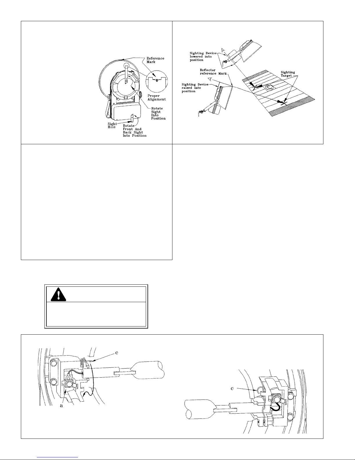
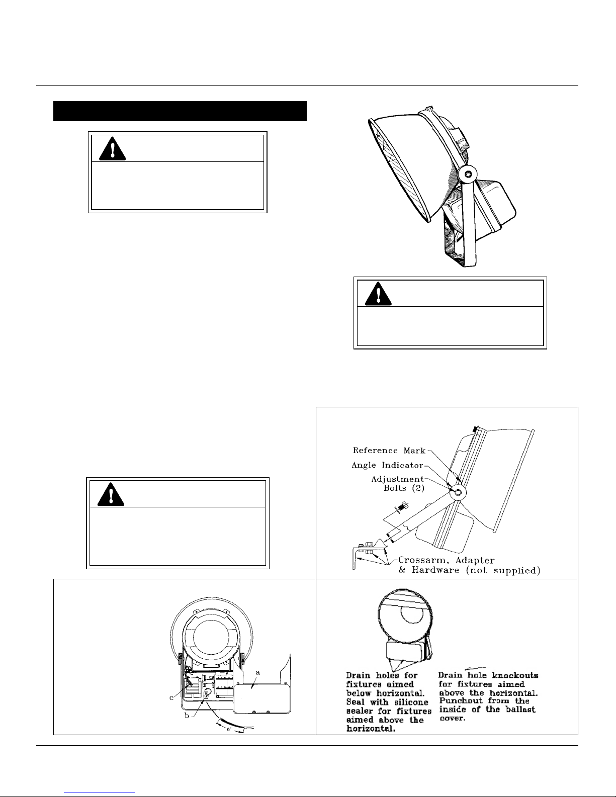
Step 4 — LUMINAIRE AIMING
Two sighting systems are provided for your convenience.
Use the sight system which is most easily accessed.
Optical Sight:
A. Rotate sight into vertical
position.
B. Align the reference mark
of top of reector ange
with notch in sight for
proper aiming.
Base Sight
A. Rotate front and back
sight into vertical posi-
tion.
B. Align the two sighting
holes for proper aiming.
Step 5
After positioning luminaire, tighten all mounting
hardware.
Step 6
Connect power cable to suitable supply in accord ance
with all applicable codes.
INSTALLATION CLEANING:
DO NOT CLEAN INTERNAL OPTICAL SYSTEM
The Ultra✭Sport oodlight has been specially recleaned at the
factory. Field cleaning of the internal optical system during
installation is not recommended.
EXTERNAL CLEANING
Initial cleaning of the outside of the glass lens may be
required to ensure optimum optical eciency.
Clean front glass with a mild soap and water solution
rinse clean and wipe dry.
CLEANING INSTRUCTIONS AND CAUTIONS
CAUTION
Risk of burn
• Allow lamp/xture to cool be-
fore handling
Caution: Do not touch quartz tube lamp with bare
hands! If lamp is handled, nger prints, grease or oils
should be removed from the lamp with isopropyl alcohol.
This will remove material which cause whitish spotting
and premature lamp failure. Dry lamp carefully with cotton or clean cloth.
PERIODIC CLEANING WHEN RELAMPING:
INTERNAL:
Should the internal reector system require cleaning,
use only non-abrasive, neutral (pH 6-8) cleaner containing no chlorinated or aromatic hydrocarbons.
Rinse clean and wipe dry.
EXTERNAL:
Clean front glass with a mild soap and water solution, rinse clean and wipe dry.
NOTICE: Drain holes are provided in the proper loca-
tions for customary mounting positions. If oodlight is
to be aimed up above the horizontal, it is necessary to
punch out the two knockouts in the rear ballast cover
and plug the three front housing drain holes with a
suitable material such as silicone RTV.
LAMP REPLACEMENT
A. Insert the lamp terminal into the
socket terminal (a) at both ends of the
lamp and tighten screws.
B. Slide the lamp ends into the sockets.
C. Latch the lamp retainers (c).
D. Close and rebolt the relamping door. Tighten
bolts to 50 in. lbs. torque.
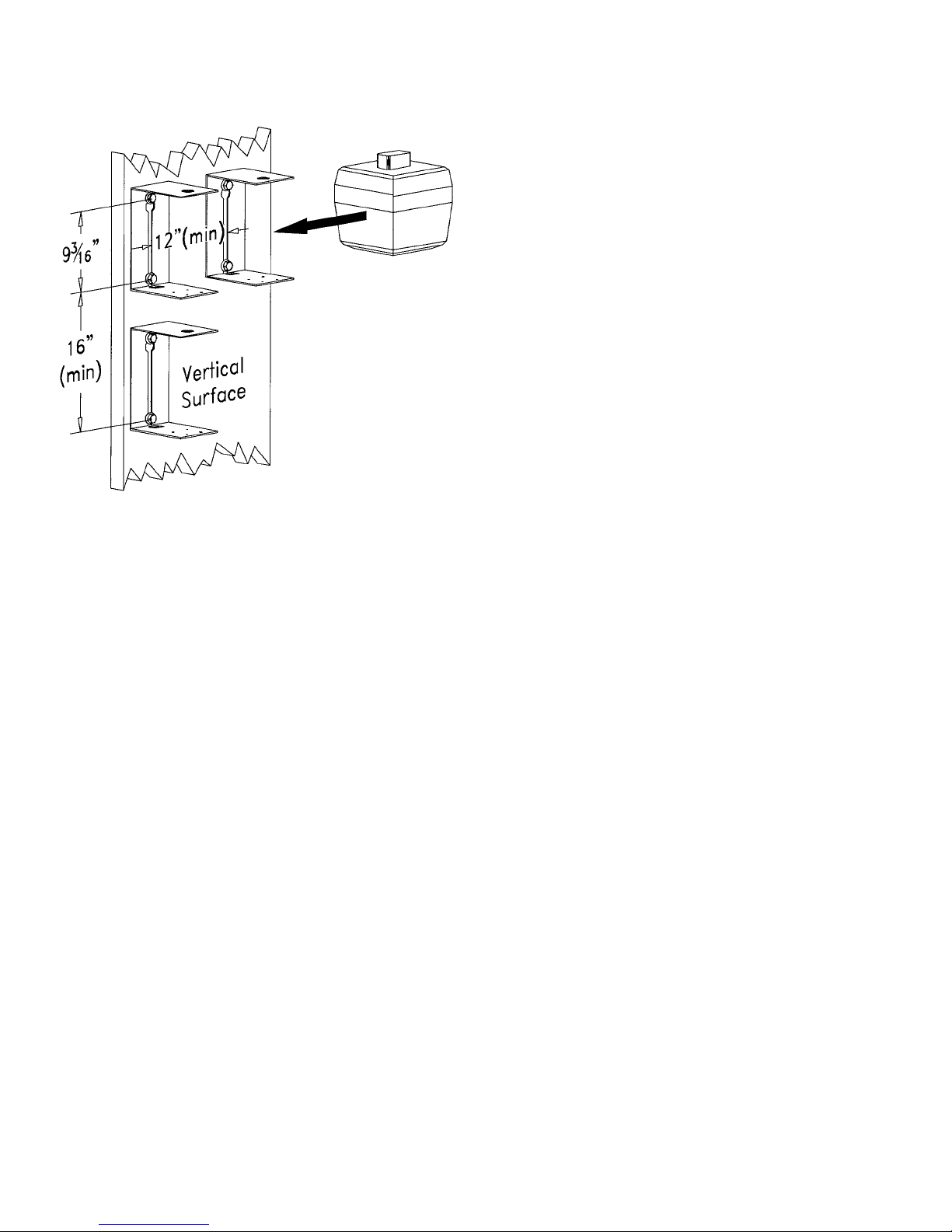
REMOTE BALLAST MOUNTING
See below illustration for bolt spacing and bracket mini-
mum spacing.
 Loading...