

Page 1
-.
—-
‘*
UseandCare
ProblemSolver
RepairService
Installation
What’sinThisKit 5
OtherPartsYouWillNeed 5
InstallingtheWaterLine 9-11
Warranty BackCover
Models
UK-KI’P4
2
4
5-:
UK-KI’I?5
These kitsfitmostmodels cdl-
ingforUK-KIT-IcmUK-KIT-2.
Can beused inall“M” (1971)and
later GE and Hotpoint refrigerators except those with an ice
dispenser.
UK-KIT-4 isdesigned for all topfreezer no-frost refrigerators 1’7
cu. ft. and larger and allside-byside models exceptthose with an
ice dispenser.
UK-KIT-5can be used in all 14
through 16 cu. ft. top-freezer
no-frost refrigerators.
If youarereplacinganitmmker
withUK-KIT-4 or UK-KIM, see
5.
page
Page 2
~
DOnotplacefingersorhands
ontheautomaticicemaking
mechanismwhiktherefrigerator
pluggedin, Thiswillhelp
is
protectyoufrompossibleinjury.
Itwillalsopreventinterference
withmovingpartsoftheejector
mechanismandtheheating
elementthatreleasesthecubes.
Undercertainrarecircumstances,
icecubesmaybediscolored,
usuaiiyappearingwithagreen-
Muishhue.
unusualdiscolorationisapparently
acombinationoffactorssuchas
certaincharacteristicsoflocal
waters,householdplumbingand
the accumulationofcoppersaltsin
aninactivewatersupplylinewhich
feedsthe icemaker.Continued
consumptionofsuchdiscoloredice
cubesmaybeinjurioustohealth.If
suchdiscolorationis observed,
discardtheicecubesandcontact
the dea~erfromwhomtheicemaker
orrefrigeratorwaspurchased,a
FactoryServiceCenter,oran
authorizedCustomerCare”
servicer.
Thecauseofthis
InletTube-@
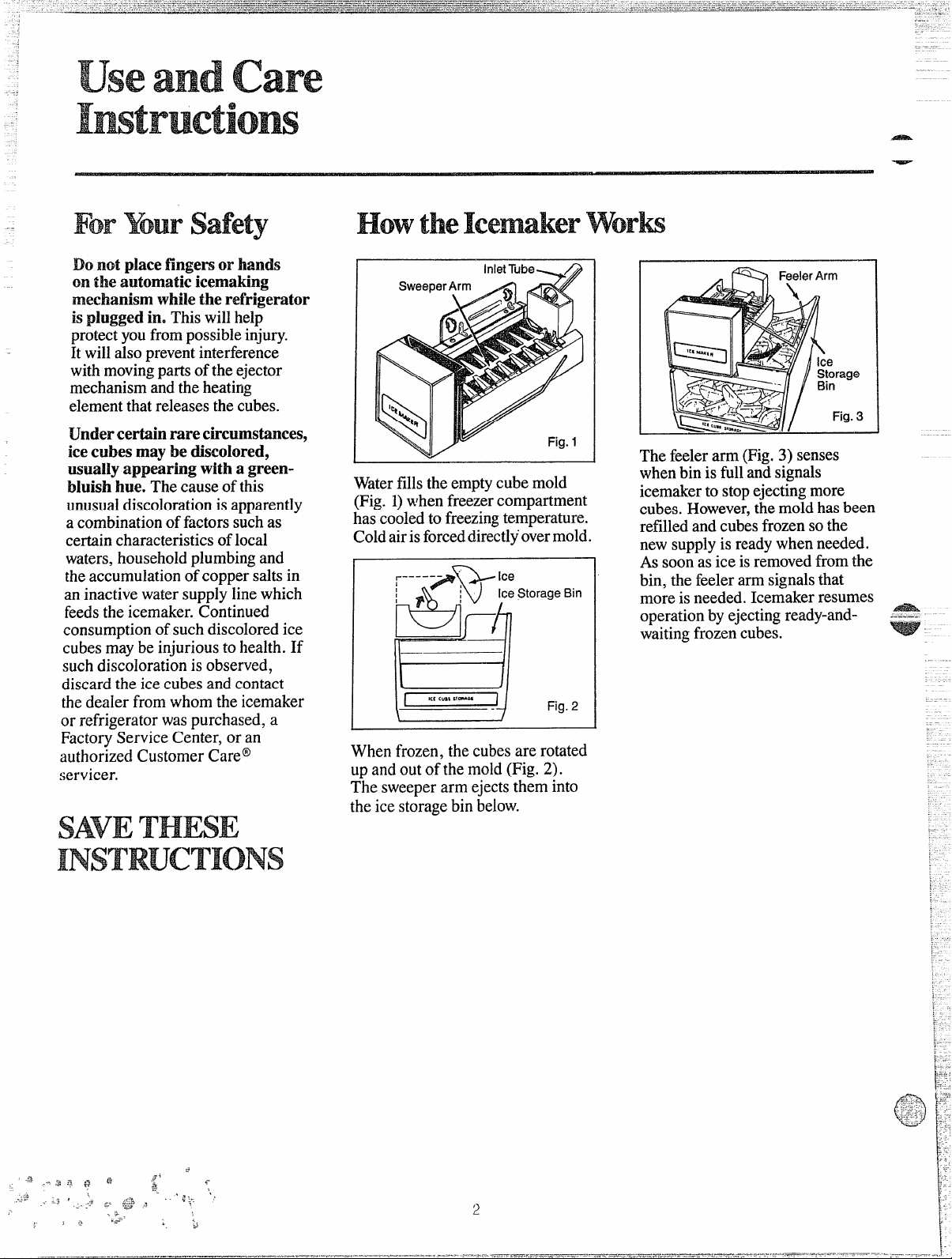
Waterfillstheemptycubemold
(Fig.1)whenfreezercompartment
has-co~ledtofreezingtemperature.
Coldairisforceddirectl~overmold.
r----P;
~P :
R-
Ice
Ice Storage Bin
C&l
ICCC“*S11-M
H
Whenfrozen,thecubesarerotated
upandoutofthe mold(Fig.2).
Thesweeperarmejectsthem into
theicestoragebinbelow.
Fig. 2
The feeler arm(Fig.3)senses
whenbinisfullan~signals
icemakertostopejectingmore
cubes.However,the moldhasbeen
refilledandcubesfrozensothe
newsupplyisreadywhenneeded.
Assoonasiceisremovedfromthe
bin,the feelerarmsignalsthat
moreisneeded.Icemakerresumes
operationbyejectingready-andwaitingfrozencubes.
Page 3
touse
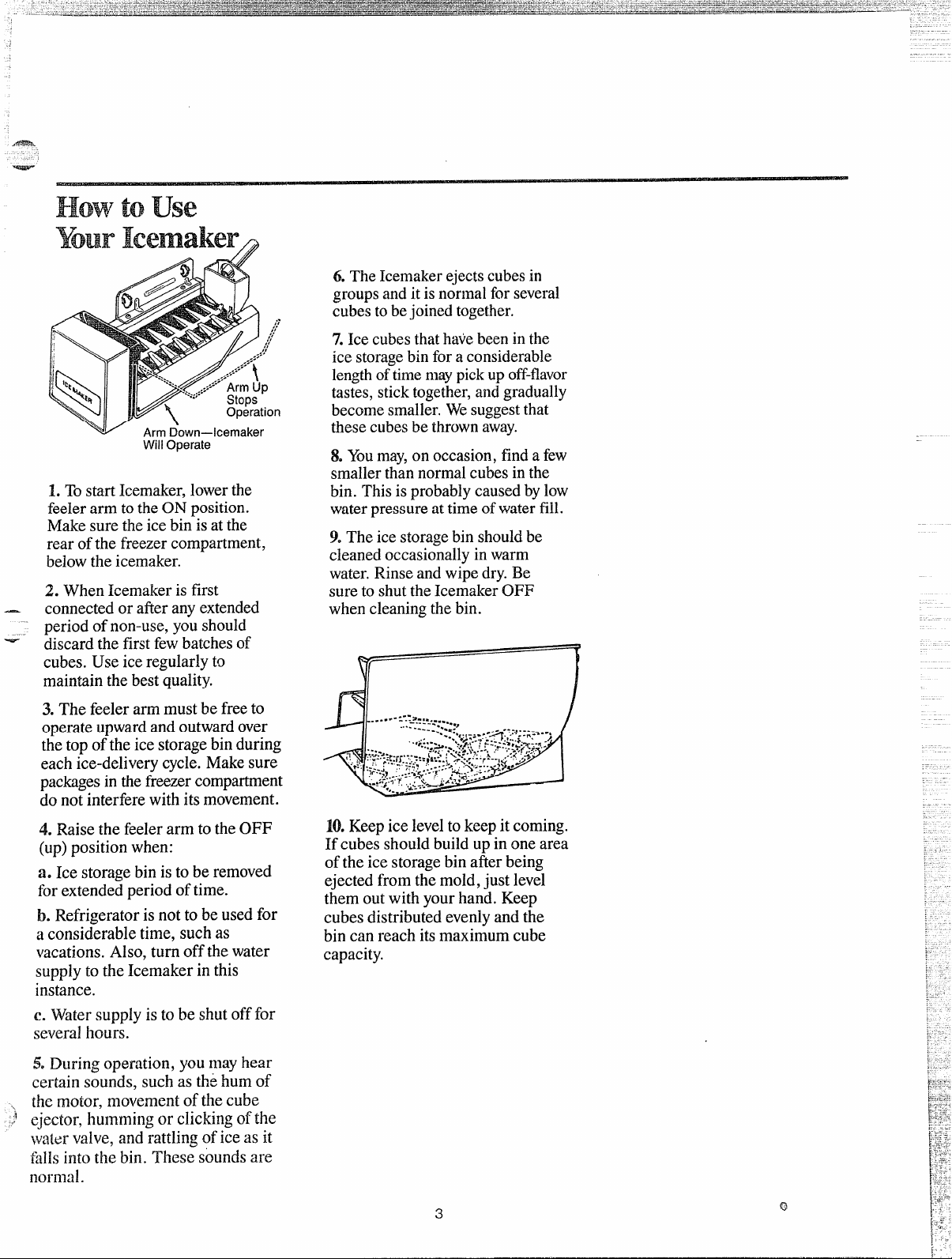
Will Operate
TostartIcemaker,lowerthe
1.
feelerarmtotheONposition.
Makesurethe icebinisatthe
rearofthefreezercompartment,
belowtheicemaker.
2. WhenIcemakerisfirst
connectedorafteranyextended
~eriodofnon-use.voushould
-
~iscardthe firstfe~ batchesof
cubes.Useice regularlyto
maintainthebestquality.
6.TheIcemakerejectscubesin
groupsandit isnormalforseveral
cubestobejoinedtogether.
7.Icecubesthathavebeeninthe
icestoragebinforaconsiderable
lengthoftimemaypickupoff-flavor
tastes,sticktogether,andgradually
becomesmaller.Wesuggestthat
thesecubesbe thrownaway.
8.Youmay,onoccasion,findafew
smallerthannormalcubesinthe
bin.Thisisprobablycausedbylow
waterpressureattimeofwaterfill.
9.Theicestoragebinshouldbe
cleanedoccasio-nallyinwarm
water.Rinseandwipedry.Be
suretoshuttheIcemakerOFF
whencleaningthebin.
3.Thefeelerarmmustbefreeto
operateupwardandoutwardover
the topoftheicestoragebinduring
eachice-deliverycycle.Makesure
packagesin the freezercompartment
donot interferewithitsmovement.
4. RaisethefeelerarmtotheOFF
(up)positionwhen:
a. Ice storagebinistoberemoved
forextendedperiodoftime.
b. Refrigeratorisnottobeusedfor
aconsiderabletime,suchas
vacations.Also,turnoffthewater
supplytotheIcemakerinthis
instance.
C. Watersupplyistobeshutofffor
severalhours.
5,Duringoperation,youmayhear
certainsounds,suchas th~humof
themotor,movementofthecube
ejector,hummingorclickingofthe
watervalve,andrattlingoficeas it
faHsintothebin. Thesesoundsare
normal.
10.Keepiceleveltokeepit coming.
If cubesshouldbuildupinone area
oftheicestoragebinafterbeing
ejectedfromthemold,justlevel
themout withyourhand.Keep
cubesdistributedevenlyandthe
bincanreachitsmaximumcube
capacity.
Page 4
.— ~
use
save‘timeand ● e you service,checkthe
CAUSEAJ?m
—.
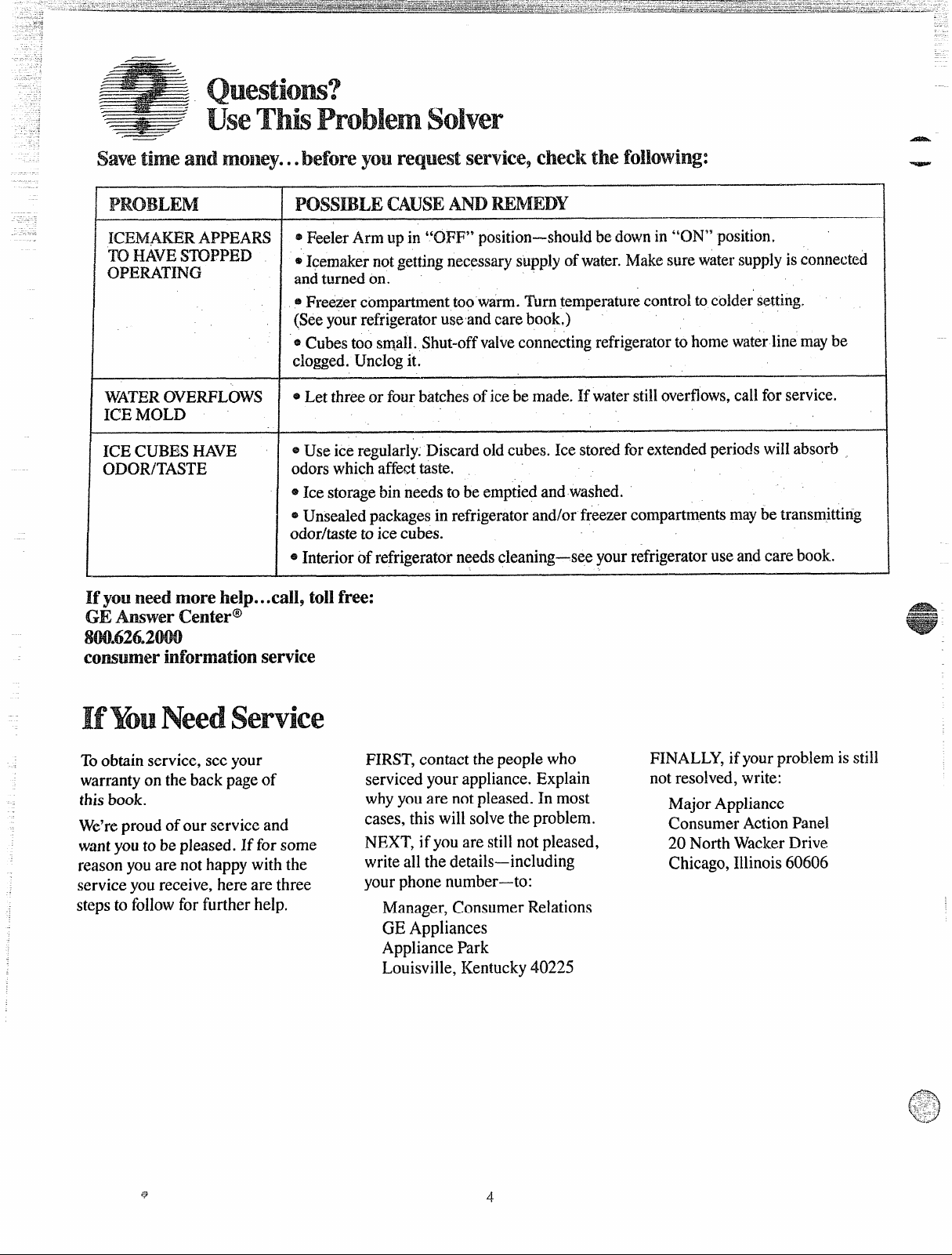
ICEh@.KER.APPEARS
m HAVE!SmPP13D
OPERATING
W?ATEROVERFLOWS
ICEMOLD
ICECUBESHAVE
ODOR/TASTE
*FeelerArmupin “OFF” positicm—slmuklbedownin“ON”position”
@Icemakernotgettingnecessarysupplyofwater.IvIaktisurewatersupplyisconnected
andturnedon.
@Freezercompartmenttoowarm.Turntemperaturecontroltocoldersetting,
(Seeyourrefrigeratoruseandcarebock)
*Cubestoos~aH.Shut-offvalveconnectingrefrigeratortohome waterlinemaybe
clogged.Unclogit.
= Letthreeorfourbatchesoficebemade.Ifwaterstilloverflows,callforservice.
~Useiceregular~yrDiscardoldcubes.Icestoredforextendedperiodswillabsorb
odorswhichaffecttaste.
~Icestorage
*Unsealedpackagesinrefrigeratorand/orfreezercompartmentsmaybetransmitting
odor/tastetoicecubes.
@Interiorofrefrigeratorneedscleaning—seeyourrefrigeratoruseandcarebook.
Ifyouineed!rlnOre I’ldp...cau,tollfree:
GEAnswerCentero-
cmsumerinformationservice
binneedstobeemptiedandwashed.
Toobtainservice,seeyour
warrantyonthebackpageof
thisbook.
We’reproudofour serviceand
wantyouto bepieased.If forsome
reasonyouare nothappywiththe
serviceyoureceive,herearethree
stepsto followforfurtherhelp.
FIRST,contactthepeoplewho
servicedyourappliance.Explain
whyyouarenotpleased.In most
cases,thiswillsolvetheproblem.
NEXT’,ifyouarestillnotpleased,
writeallthedetails—including
yourphonenumber—to:
Manager,ConsumerRelations
GEAppliances
AppliancePark
Louisville,Kentucky40225
‘4
FINALLY,ifyourproblemisstill
not resolved,write:
MajorAppliance
ConsumerActionPanel
20NorthWackerDrive
Chicago,Illinois60606
Page 5
Areyou repkmcingan
withthis kit?
H’simportantthatyouusethe
watervalveandfilltube
extension
even though your refrigeratormay
alreadyhavethem installed.
TheOMvalvewillnotallow enough
waterthrough to fill the icemaker
properlyand cancausedamage.
Thefili tube extensionneedsto
beadifferent lengththan the
original tube for proper waterflow.
Cutthe tube to the length indicated
foryourmodel of refrigerator.
—
thatcome with thiskit
F%cy$8“16Cxmtainsix
different
instructions.
The actual installationofthe
icemakerwill depend onwhich
model refrigeratoryouhave.There
isa label on the back of the
refrigeratorthat will tell you
whetherto use InstructionA, B,C,
D,Eor F.
.’
5
Page 6
@
@ -==-
Slotted Hex-HeadScrew
CD
Adhesive43ackedFasteners
l-loseCiamp
0
——
@
Iilslaw..
Date
Ueii!d3r.-.—..._..._ -_ ..––__
WarrantyLabel
Ice Bucket
-.
@
—
WaterLine Clamp
WaterLine Clamp
(usedonlywith
Instruction Sheet F)
@
(he & Care
hstructicms,
tmd
“., ,, - -. ...-.,:.:,’
. --.
‘.
N,
,>.
. ‘. .- .-J
.-.+,:.;$7:
::-,..
t“’,
f\c-
i3
Page 7

us-r
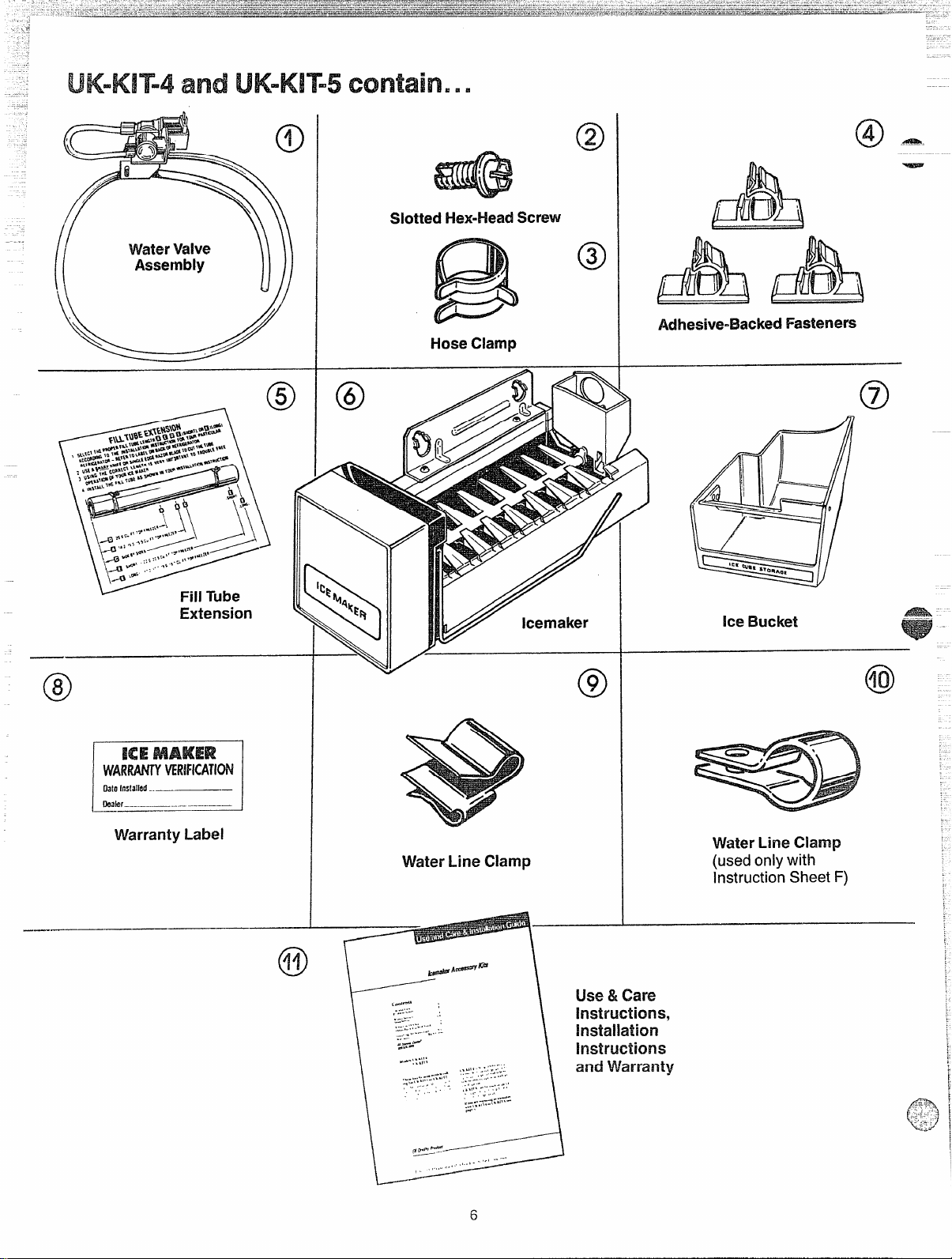
1. WaterValveAssembly
2. SlottedHex-HeadScrew
3. HoseClamp
x
x x
x X1X
x
lx
x
I
x
I
I
x
x
x
x
I
x
I
x
I
NO
I
x
I
4. Adhesive-BackedFasteners
5. FillTubeExtension
6. Icemaker
7. Ice Bucket
8. WarrantyLabel x
9. WaterLine Clamp
10. WaterLineClamp
11. LJserInstruction and Warranty x
PARTSYou NEED...
Coppertubing, shut-offvalve andfittings necessary
to supplywaterto your refrigerator are not included
in UK-KIT-4or UK-KIT-5.
Youcanpurchase a compiete water supply kit from
your GEor Hotpoint dealer.
Recommended water supply kitsareCat. No.
WX8X2(15feet of copper tubing), WX8X3(20feet),
or WX8X4(25 feet).
——.——
x
x x
x
x
-+--t+-
x x
NO
x
x
NO I NO
x
UK-KIT-5also contains a bucket support for useas
described in Instruction A.
ForInstruction B only... you will need a higher
bucketsupport and different fill tube extension.
See page 12.
x
I
x
I
x
I
x
I
1
x x
~lxlx
‘x
x
x
X
x
NO I NO
x
I
x
I
x
I
x
I
x
I
x
I
x
I
x
I
x
I
x
I
No
I
x
I
x
I
7
Page 8

-m=
Read each
before prfxxxxiirg.
Txds needed:
@Phillips”typescrewdriver
@Elk3de-typescrewdriver
oMap knife
~Pliers
step Wmxg@y
1
2
Atbottomof rearof refrigerator
remove2screwsholding
compressorcompartmentcover
(if covered)andsavethemfor
reinstallationlate~Bendcoverback
for accessto thecompartment.
* Loc~tefemaleconnectorplug
(A)whichis attachedtocabinet
byawiretie.Removewiretie
and discardit.
=1Removeanddiscardtapefrom
femaleconnectorandplug onto
male terminalsonwatervalve
(1).Eitherwirecangoon either
terminal.
4
~Pushmetalclamp(9)ontolower
flangeofcabinetbackdirectlyin
linewith watervalveasshown.
Checkplasticwa@rIirwnutori
bottomofwatervalveto besureit
ishandtight.DONOTUSETOOLS.
~Mf3talclampisforcoppertubein
~ housepiumbing.Nottobewedfor
~ piastictubingfromthewatervaiv.o.
~Re-installcompressor
compartmentcoverso plastic
waterlineisdirectedoutof
compartmentandupbackof
refrigerato~Fittingonwatervalve
shouldextendthrough holein
coverasshown.
Note:Onsomemodels,youmay
haveto usescissorsto cut the
compressorcompartmentcover
iustenoughtoallowthewater
~alveinletto stickoutsothe
copperwaterlinecanbe
connectedtoit later.
—
6
* Removesmallplasticcap(B)
frombottomoffill tubeinlet
locatedinupperrightrearcorner
cf refrigerator.Squeezeendsof
hoseclamp($)from kit with
pliersandslideclampovwfill
tubeinlet.Whilestill squeezing
clamp,inseflplasticwaterline
intoinletasfarasitwill go
(approximatelyV). Thenslide
clampdownwardtocapture
plasticwaterlineinplace.
* Makesurefill tubeinletis
aimeddown asshownbelow.
1
@
(Remove)\
‘7’
Fastenplasticwaterlinetp bqck,
ofcabinetwith adhesive-backecf
fasteners(4), spacingfasteners
asshownto takeupslackinline.
(c) Fastenwatervalveto cabinet
edge hole(X)usingslotted hexhead screw(2)from kit. DONOT
DRILLANYADDITIONALHOLES.
5
On mbdelsthat havecondenser
tubinaonbackofcabinet,insert
thepbstic waterline between
tubingandbackofcabinet.
~=
h
as
fdiEh
0-
Adh8sivL?-back6tifK@IfNS
forplasticwatwline
WAdhr3sivMacWl fasterm
forplasticWM lin~
Page 9

FM?adeach step
*
——..——-—..——.—.
before pilxx?eding.
“rods needed:
~ screwdriver
~Bkk-type
efi14;fI’lutdrh%?r
@Sharp knife
@Pliers
screwdriver
3
(a)Locatefemaleconnector
plug(C)whichisattachedto
cabinetbyametalclip.Remove
clip byremoving screw.Save
screw for mounting the water
valve late~ Discard clip.
(d)Checkplasticwaterlinenuton
bottomof w~tervalveto besureit
is handtight. DONOTUSETOOLS.
%Putcompressorcompartment
coverbackinplaceso plastic
waterlineis directedoutofthe
topofthecompartment!Replace
screw(A),removedinStep2+
Note:Onsomemodels,youmay
haveto usescissorsto cut the
compressorcompartmentcover
justenoughto allow thewater
valveinletto stick outsothe
copperwaterlinecanbe
connectedto it later.
6
~ Removesmall plastic cap(D)
from bottom of fill tube inlet
locatedinupperright rearcorner
of refrigerator.Squeezeends of
hoseclamp(3)fromkit with
pliersandslideclampoverfill
tubeinlet,Whilestill squeezing
clamp,insertplasticwaterline
intoinletasfarasit wili go
(approximately1“), Thenslide
clampdownwardto capture
plasticwaterlineinplace.
* Makesurefill tubeinletis
aimeddownasshownbelow.
———
1
2
Atbottomof rearof refrigeratofi
remove 2screwsholding
compressorcompartmentcover
and savethem for reinstallation
later Bendcoverbackfor access
tothecompartment.
(I)
(ii’)
(b)Plug female connector onto
male terminals on water valve
(1). Either
terminal.
(c) Fastenwatervalveto cabinet
edgehole(X)usingslotted hexhead screwthatyouremovedin
Step3 (a). DONOTDRILLANY
ADDITIOhlALHOLES.
wirecangoon either
QM-
inlet———4—
7
Faste~p;asticwaterlineto back
ofcabinetwith adhesive-backed
fasteners(4), spacingfasteners
asshowntotakeupslackinline.
5
Attachwaterlineclamp(10) from
kitto refrigeratorfor safekeeping
untilyouconnectthe house
waterlineto the icemakerwater
valve(seepage17).Drivescrew
(El), removedinStep2, into
cabinetedgethroughclampand
holeincompressorcover.
Beforetheicemakerisoperated,
theclampmustattachthecopper
waterlineto the refrigeratorto
helpavoidunduewearonthe
tubingthatmight causeleaks.
Acihesive-k2ackedfasteners
for plastic water line
(continued next page}
‘a
Page 10

Follow instructions in appropriate Step 8A below.
step %34
I
Removeicetray tunnel.
o Disengageicetunnelside andbot-
tomfromretaininghooks.Lowert!.mneluntil side is clearof freezershelf
and removeit from freezer.Discard
icetunnel.
step8A
Removeice
o
Removetwo screws (C) andsave
themforinstallationof icemaker.
e Lift ice traytunneloff plastic hook
(D)anddiscardit.
traytunnel.
step 8A
step8A
Renmveice
~ As
with bladeof screwdriver,pull tunnel
forwardand out. Discardicetunnel.
traytunnel.
vou lift tabonleft sideintunnel
SW38A
.
—
Removeicetray shelf.
e Pullicetrayshelfto disengage
pinsfromholesoncabinetwaii.
,
“ Tilt ice travshelfandremoveit.
Discardshe~.
-
Removeice trayshelf.
Lift ice tray shelf upto disengage
;romtabs oncabinetwall and pull it
forwardasshown.
o Tilt ice
Discardshefi.
trayshelf andremoveit
Follow instructions in appropriate Step 85 IMow.
To repositiorlthe 2-piecesht?lf
:
10
Page 11

step9
.—-..-+.......
Removescrew(A)that holds electrical~lugcoverinplace.Discardscrew
andcover.
A
step10
DRemoveplastic insert (B) from air
ductand discardit.
o Loosen two icemaker mounting
screws (C) armroximately1/2”. DO
step11
Cutthefill tubeextension(5)tothen
length with a sharp knife or singleedaerfizorbladeand slide it onthefill
tu&?againstthestop
step12
Place icemakerin freezercompartmentasshown.Inserticemakerpower
cordplug(II) intosocketonsidewall,
makingsure prongsare matchedto
correspondingholesandplugisfirmly
seatedinsocket.
step13
0Lifticemakerandpositionrearopen-
ing in fill cup (E) overfill tube extension (5). Hang icemaker on two
screws(C).
Makesure:
● electrical plug is still firmly in
socket.
~fill tubeextension(5) is still in fill
CUPopening–Checkrearof refrigerator to makesure fill tube has not
beenpushed out of the backof the
refrigerator.
.
icemakermountingscrews are locatedinuppermostpositionof mountingslots.
THENTIGHTENICEMAKERMOUNTINGSCREWSSECURELY
step34
Theicemakershouldfeelsecurewhen
youlift theicemakerfeelerarm(F)to
the“OFF”(up)position.Leaveitthere
until the refrigeratoris connectedto
thewatersupplytopreventpremature
operation.
r /7
icemaker
F ~qilloperate
“c)
step15
Replacefreezershelf. Movebucket
supportandicebucket (7) into place
directly under the icemaker. See
illustrationbelow.
NOTE:Checkagaintomakesurothe
icemakerpowercord
sorted into its soclmt
matcf’iedto correspondingholes.
Checkagain to make sure the icemakerf6elerarm(F)
(up)position.
SWi?p 16
Alabel($)isprovidedinthekitto record
the date of installationfor warranty
purposes.Applyit to the backof the
refrigerator.
plugisfullyln-
with ~rongs
is inthe“OFF”
step17
Thewarrantyfortheice~akerk$prir!tedanthehackgageofthi~bo~klet.Keep
thisbookletwithyourRefrigeratorWe &Carebook.
Theicemakerinstallationisnowcomplete.Refertowaterlinehook-upinstructions
onthebackoftherefrigeratorfOrconnectiontohomewatersupply.Afterwaterline
installationis completed,lowericemakerfeelerarmtothe“ON” (dawn)position.
Tireicen?akhgqfc!e w~llnotbegifl until theictw?akerandfreezercompartment
reachoperatingtemperature,/henicemakingwill beginautomaticdily.
_—._J
—
Page 12

MODELSTHAI’CALLF(N3THIS
.- ...--- -.—-..-”-.-..-—--
1
.—
BELfsim ON
SHEETNEED A
SUPPORTAwl
FILLTUBETHANIS
ml
Ttmm.THIS
M.wqwlm Clul mm’
I’vlfxmsWin-f
ii
Obtainthisnewsupportandafilltube
extensionatnochargebyrequesting
Pub. No. 2-1003 from General
Electric Publications, c/o Dri-View
iManufacturingCo., 4706Allmond
Ave.,Louisville,KY40209.
step9
eRemovescrew(A)thatholdselectricalplugcoverinplace.Discardscrew
andcover.
e Loosen two screws (C) approxi-
mately1/2”. DONOTREMOVETHE
SCREWS.
step12
● Lifticemakerandpositionrearopen-
inginfill cup(E) overfill tubeexten-
sion(5).Hangicemakeron twoscrews
(c).
Makesure:
oelectrical plug is still firmly in
socket.
efill tubeextension(5) is still in fill
cupopening–checkrearof refrigerator to makesure fill tube hasnot
been pushedout of the backof the
refrigerator.
@icemakermountingscrewsare lo-
catedinuppermostpositionofmountingslots.
THENTIGHTENICEMAKERMOUNTINGSCREWSSECURELY.
icemaker
willoperate
F
c)
step14
Replacefreezershelf. Movebucket
supportandicebucket(7)into place
directly under the icemaker.See
illustrationbelow.
NOTE:Checkagainto makesurethe
icemakerpowercordplugis fully insefied into its socket with prongs
matchedto comespondingholes.
Checkagainto makesure the icemakerfeeler arm(F) is inthe“OFF”
(up)position.
step15
Alabel(8)isprovidedinthekittorecord
the dateof installationfor warranty
purposes.Applyitto thebackof the
refrigerator,
step 16
warranly for the icemakeris
The
printdonthebackpage ofthisbookh?t.IWp this booklet with your
Ilefrigerator(ke& Carebook.
Theicernakerinstallationisnowcom-
plete. Refer to water line hook-up
instructionsontheback of the refrigeratorfor connectionto homewater
supply,After wateriine installationis
completed,lowericemakerfeelerarm
tothe“ON” (down)position.
Icemakingcycle will not beginuntil
icemakerandfreezer compartment
reach ofleratina temperature, then
icemakiig wil[ tieginautomatically.
Cover
I
i
!
rrirmov~d
1
k=-=.-”.
step10
Takethefill tubeextension(5)fromthe
supplementarykit 2-1003thatyougot
bymail andslide it ontothe fill tube
againstthestop.
Plac(?icemaker in freezer compart-
nwntasshown.Inserticemakerpower
cwd +UU(D)intosocketonside wall,
tmhing surwprongsare matched(o
corrcspontfingholesand pluQis firmly
S[?JftlIl ill SOCket.When
cord plug shouldfit flush to
pow
f[ct.wr wall.
inser~efi,
I
#
step13
Theicemakershouldfeelsecurewhen
yotjlift tile icemakerfeelerarm
the“OFF”(up)position.Leaveitthere
until the refrigeratoris connectedto
the watersupp~yto preventpremature
operation.
(F)to
I
ICEMAWI
1I
II
ill
II /4===
4
-{2
Page 13

step9
..—————
..———
—.-——.. -—..... . .
. . . .
... ,. . .
..4.—.-—.——r
0Removescrew(A) that holdselec-
trical ~lug cover in place. Discard
screwandcover.
0 Removelight shield insert (B) and
discarrtit.
o Loosen two screws (C) approximately1/21!DONOTREMOVETHESE
SCREWS.
step10
Cutthefill tubeextensiort(5)tothea
length with a sharp knife or singleedgerazorbladeand slide it ontothe
fill tubeagainstthestop.
step11
Place icemakerin freezercompart-
mentasshown.Inserticemakerpower
cordplug(D)intosocketonsidewall,
makingsure prongs are mafchedto
correspondingholesandplugisfirmly
seatedinsocket.
step12
0Lift icemakerandpositionrearopening in fill cup (E) over fill tube ex-
tension (5). Hangicemakeron two
screws(C).
Makesure:
electrical plug is still firmly in
o
socket.
ofill tubeextension(5) is still in fill
cup opening–check rearof refrigerator to make sure fill tube has not
beenpushedout of the backof the
refrigerator.
oicemakermountingscrewsarelo-
catedin uppermostpositionof mountingslots,
THENTIGHTENICEMAKERMOUNTINGSCREWSSECURELY
step13
Theicemakershouldfeelsecurewhen
youlift the icemakerfeelerarm(F)to
the“OFF”(up)position.Leaveitthere
until the refrigeratoris connectedto
thewatersupplyto preventpremature
operation.
icomaker
F willoperate
I
o
step14
Put icebucket (7) into placedirectly
undericemaker(totheleftand allthe
way to the rear of the shelf under
icemaker).
NOTE:Checkagainto makesurethe
icomakerpowercordplugisfullyinserted into its socket
matchedto correspondingholes.
Checkagainto makesure icemaker
feelerarm(F)isin“OFF’’(UP)position.
step15
Alabel(B)isprovidedinthekitto record
the dateof installationfor warranty
purposes.Applyit to thebackofthe
refrigerator.
step-16
The wmmty for fhe icernakwis
priotedonth~backpage ofthisbookM. Keep this MoWA with your
RefrigeratorMe&Care book.
Theicemakerinstallationisnowcom-
plete. Refer to water line hook-up
instructionsonthe backoftherefrigeratorfor connectionto homewater
supply.Afterwaterline installationis
completed,lowericemakerfeelerarm
tothe“ON” (down)position.
Icemakingcycle wiil frol beginwrtil
icemakerad freezer comfx?ftmeflt
reach operating temperature, then
icemakiflgWMbeginautomatically.
with prongs
13
I
[
Page 14

---
..—
step$l
Removeand discard electric plug
coverandmountingscrew(A).
r II I
‘--==%. “
-1
m
A
@—,
0
Soe
4
Cover
removed
F!!!l
step10
Removeanddiscard plate (B) from
frontof air duct.
edgerazorbladeandslideit ontothe
fill-tubeagainstthestop,
StepK?
Placeicemakeronrelocatedshelf in
freezercompartmentasshown.Insert
icemaker power cord plug (D) into
socket on side wall, making sure
prongsare matchedtocorresponding
holes and
socktt
plug is firmly seated in
Makesure:
odectrical plug is still firmly in
socket.
~fill tubeextension(5) is still in fill
cupopening–checkrearof refrigerator to makesurefill tube hasnot
beenpushedout of the back of the
refrigerator.
oicemakermountingscrews arelocatedin uppermostpositionofmountingslots.
THENTIGHTENICEMAKERMOUNTINGSCREWSSECURELY.
Step 15
Theicemakershouldfeelsecurewhen
you lift the icemakerfeelerarm(F)to
the“OFF” (up)position.Leaveitthere
until the refrigeratoris connectedto
thewatersupplytopreventpremature
operation.
icemaker
F willoperate
‘o
step16
Moveicebucket(7)intoplacedirectly
undericemaker.Seeillustrationbelow.
NOTE:Checkagaintomakesurethe
hxmakerpowercordplug isfuliyinserted into its socket
matchedto correspondingholes.
Checkagainto makesure the ice-
maker feeler arm (F) is in “OFF”
(up)position.
step 17
A label(8) is providedin the kit to
recordthedateofinstallationforwar-
rantypurposes.Applyittothebackof
therefrigerator.
step 18
The warranty for the icemakeris
printedonthebackpageofthisbook-
Iet. Keep this booklet with your
RefrigeratorlJse&Carebook.
Theicemakerinstallationisnowcomplete. Refer to water line hook-up
instructionsontheback of the
eratorfor connectionto home
supply.After waterline installation
cGmpleted,lowericemakerfeelerarm
tothe“ON” (down)position.
Icemakingcycle willnotbeginunlil
icemakerafid freei!er compartment
reach operating temperate, then
icemakinflwill beginautomatically.
with prongs
step11
0 Loosen two screws (C). Replace
them if youremovedthemwhentakingout the ice tray tunnel.
Screws should extendapproximately
1/2” out from freezerwall.
Sw$p12
Cu[[hefill WC extension(5)tothem
ILuIC:hwith a sharp l-wife or single-
—
step1’4
o Lift icemakerandpositionrearopeninginfill cup(E)overfill tube extension
(5).Hangicemakerontwoscrews(C).
14
Page 15

—
-m
‘“-
-.
—.
step9
= Removeand discard electric
coverandmountingscrew(1!}
—
@—
0
●00
Cover
A
0
removed
step10
Ifgrille(B)isnotinplacesoits louvers
directairtotheleft,turn itasfollows:
~ Removescrew (Bl) which holds
grille(B).
DRemovegrille (B), rotate it 90°
counterclockwise,andreinstall it as
1
shownbelow.
plug
Removeanddiscardwhiteplugfrom
upperleftcorneroffreezerwall.
~Cutthefilltubeextension(5)tothe
❑SHORTlengthif yourrefrigerator
is22.0or22.5cubicfeet(usea
sharpknifeor single-edgerazor
blade.)Otherwiseusethe
length.Slidetheextensiononto
thefill tubeagainstthestop.
step12’
❑long
step14
~Lift icernaker and position rear
openingin fill
extension(5). I-fangicemakerontwo
screws(C).
Makesure:
electricalplug is still firmly in
o
socket.
e
fill tubeextension(5)is still infill
cupopening–check rearof refrigerator to makesurefill tube has not
been pushedout of the backof the
refrigerator.
oicemakermountingscrewsarelocatedinuppermostpositionofmountingslots.
THENTIGHTENICEMAKERMOUNT-
ING SCREWSSECURELY.
cup(E]overfill tube
step16
Moveicebucket(7)intoplaceonshelf
directlyundericemaker.
NOTE: Checkagaintomakesurethe
icemakerpowercordplugis fuilyinserted into its sock@
matchedto correspondingholes.
Checkagainto makesure icemaker
feelerarm(F)isin“OFF’’(up)position.
with prongs
step17’
Alabel(8)isprovidedinthekitto record
the dateof installation for warranty
purposes.Applyit to the backof the
refrigerator.
1
step13
m
{&’
C@
.-.-,
.“4
---. *
(iijliiil~.
o Replacescrewandtighten.
11
Loosenscrews (C) hut do not screw
them all {hewayout. Screwsshould
exte[?d~pproxirmtely 1/2” out from
freeze!wall
l—...-.-... “----–-
>—A----
. ~-— --
——
-T-.---:-.=
i
.——- . ,..—.
---1
Place icemaker on shelf in freezer
compartment as shown. Insert ice-
makerpowercordplug(D)intosocket
orrside wall, makingsureprongsare
matchedto correspondingholesand
.
@
!,
-.
insocket.
-/-.
IT
plugiSfirmlyseated
=z.3
D
0
12’
]-
@
‘?- /
step15
Theicemakershouldfeelsecurewhen
youlift the icemakerfeelerarm(F)to
the“OFF” (up)position.Leaveitthere
until the refrigeratoris connectedto
thewatersupPlytopreventpremature
operation.
icemaker
F
will operate
‘o
15
step18
The warranty for the icemaker is
printedonthe
let. Keep ihis booklet with your
RefrigeratorLis8&Carebook.
Theicemakerinstallationis nowcom-
plete. Refer to water line hook-up
instructionsonthe backof the refrigerator for connectionto homewater
supply.After water line installation is
completed,lowericemakerfeelerarm
to the “ON” (down)position.
,,;
,,.,
,’
n
Page 16

I
~ÑÛ
~DJ
~DJ
—
~+~
~;’:
1:.:
~~-
-:.
:-
~
9
llqdacedkmtricfllugcover.
removethetypeshownin
To
Fig.1,insertstandardscrew-
chiverMadein
s!otatbottom
ofcove~apply =’
pressureup- --
wards,andpry
coverawavfrom
freezerwill.
Discardthis ‘ig”7 ‘ /
cover
ToremovethetypeshowninFig.2,
presstopof
coverdownto
freeits upper
tabfrom slotin
freezerwail.
Thenpullcover
straightoutto
freethelower =
tabsfrom their ., .:.N
slots.Save J- -
this
COW’fOr
reinstallation
MB?.
T
] Fig.2
,-zq
L
quy
D
,,
b
‘S_ -
“,.-.,,
,.-A
\
R
(b)Cutthefill tubeextension(5)
to the “F” length. (Useasharp
knifeorsingle-edgerazorblade.)
step12
(a) R6moveicemakerpowercord
from clip.Holdicemakeronin
freezercompartmentasshown.
Inserticemakerpowercordplug
(F)intosocketonrearwall,
makingsureprongsarematched
to correspondingholesandplug
I
isfirmlyseatedinsocket.
step13
@Lift icemakerand ositionrear
openingin
tubeextension(5).Hang
icemakerontwoscrews(E).
Makesure:
6
electricalplugisstillfhm!yh
socket
~cover,iftypeshowninFig.2,
has beenrfhs!alkd.
fill tubeextension(5) isstillin
e
fill cupopening–checkrearof
refrigeratorto makesurefill tube
hasnotbeenpushedoutofthe
backofthe refrigerator
eicemakermountingscrewsare
locatedinuppermostpositionof
mountingslots.
THENTIGHTENICEMAKER
MOUNTINGSCREWSSECURELY.
i
fill cup( ) overfill
step15
Positionfreezershelfforicemaking
andmm%!icebucket(7)into
placeonshelfundericemake~
Straighttwo-positionshelf
shouldbein lowerposition.Step
shelf’slowerstepshouldbe
undericernakecCantilever
shelf’stop lugsshould bein6th
slotsupfrom bottomoftrack.
NOTE:Checkagainto
theicmaker powercordis
fullyinsertedin?oitssocket
with prongsmatchedto
correspondingholes.
Checkagainto makesure
icemakerfeelerarm(H)isin
“OFF”(up)position.
makesure
10
Loos;nscrews(E)butdonot screw
them all the way out. Screws
shouldextendapproximately
1/2”outfrom freezerwall.
I
(a)R;move anddiscardwhite
pli.qfrom upperleftcorner of
freezerwall.
I
?,
/
(b) If electricplugcoverremoved
inStep9istheoneshownin Fig.
2, reinstallit.
Placecoveroverelectricplug
I
withicemakerpowercordrunning
throughbottomorsideopening
incovet dependingonorientation
of pkJg.
I
Next, put
freezerwall.Thensnapupper
tab into its slot, This
coverwill helpkeepelectric plug
from comiflg out of socketwhen
mountingice-maker.Besureto
reinslall it now.
lowertabsinslotson
I
Thei;emaker shouldfeelsecure
whenyoulift the icemakerfeeler
arm(H)to the “OFF”(up)
position.Leaveit thereuntilthe
refrigeratoris connectedtothe
watersupplyto prevent
prematureoperation.
iramaiwr
~ willoperate
“o
stepw
Alabel(8)is providedinthekit ~
to recordthedateof installation
for warrantypurposes.Applyit to thebackofthe refrigerator.
17
The forthe
is onthe backpaged
thisbooklet.
withyour Ww3
&Care Book.
Theicemakerinstallationis now ~ complete.Referto waterline ;
hookupinstructions ontheback ~
ofthe refrigeratorfor connection
to homewatersupply.After ~
waterlineinstallationis
completed,lowericemakerfeeler \;armtothe “ON” (down)positiofl.
Q@? !?W-m-IffE@z~
u~ti!icemaker~!!tiffeezef t?-.-;;::
reach @pEH3W~”-’
fi%%lLMWEMng
KM I.M$gifi
.—
--
J
E-
;
....
[:[-
;.
i
i
~
Page 17

-@4&!a
.....—-
--
you.use your re~r~gerahr bdcme
H
cmneding the water he, make sure the
ifxmdax feeler mm is kept in the “OFF”
position.
@When using any electricaldevice (suchas a
powerdrill)during installation, be sure the device
is insulatedorwired ina manner to prevent the
hazard of electric shock.
@Allinstallationsmust be in accordancewith
localplumbingcoderequirements.
This water he irwtallatio~ is not warranted
by the refrigerator or icemaker manufacturer.
Follow these instructions carefully to
rrhhize the risk
damage.
of expensive water
A cold water supply is required for
automatic icemaker operation.
Water
pressure must be between 20and 120p.s.i.
Copper tuMrig, 1/4” O.D., shouldbe used to
connect the refrigeratorto the water supply.Do
not use
plastic tubing or plastic fittings
becausethe connectionbetween the water supply
and the refrigerator water valveinletisunder
constantwater pressure. Also,certain types of
plastictubing maybecomebrittle with age and
crack,resulting inwater leakage.
shutoff valve shouldbe connectedto the cold
A
water line.The shutoffvalve shouldhavea water
inletwith a
!5/32”
mininmm inside diameter of
at the pointofconnectionto the COLD
WATERLINE. A saddle type shutoffvalve
permitted by many localplumbingcodesis shown
below.
Min. 5132”dia. opening
Checkyourlocalplumbing codesbefore choosing
this type ofvalve. Werecommend using the
saddle valvesupplied with GEWater Supply Kits
WX8X2,WX8X3and WX8X4.
1
Page 18

Fer!ule =
)/
[=!L-
Compression nut
EiMsrALLsMumFFvAtvE@w
a. Choose a location for the valvethat is easily
accessible.It is best to connect into the side ofa
verticalwater pipe. When it is necessary to
connectintoa horizontalwater pipe, make the
connectionto the top or side, rather than at the
bottom, to avoiddrawing off any sediment from
the water pipe.
lb.Drilla 1/4”hole in the water pipe, using a
sharp bit. Removeany burrs resulting from
drillingthe holein the pipe.
c. Tighten the clamp screws until the sealing
washer begins to swell.
ERoti?EcowERTuBIH8 sEvwEEMcQLn
HME
Route the tubing through a hole drilled in the
floor (behind the refrigerator or adjacent base
cabinet) as close to the wallas possible. Be sure
there issufficient extra tubing (about 8 feet coiled
into 3 tm-nsof about 10 inches diameter) to allow
the refrigerator to moveout from the waHafter
ins~allation.
—
—
Refrig3ator
connection
Place the compressionnut and ferrule ontothe
end of the tubingand connecttothe shutoffvalve.
Make sure the tubing is fuHyinserted intothe
valve.Tighten the compressionnut securely.
Before
reh-igerators be sure refrigerator power
cord
makingconnectiontothe
isnotplugged intothe wall outlet.
a. Turn water onand flush outthe tubing,making
certain that all foreign matter is removedfrom the
line.
b. Shut the water off after about one quart of
water has been flushed through the tubing.
NOTE: Some localitiesmay have sand or other
foreign matter present in the water supply in such
quantities that they may,in time, collectin the
screen ofthe water valveattached to the back of
the refrigerator and tend to reduce the water flow
to the icemaker. Where such conditionsexist, we
recommend that an additional filter or strainer be
installed in the linenear the refrigerator. If a
screen type strainer is used, it should be 80 mesh
or finer.
e. Cut off the flared end ofthe copper tubing and.
remove the flare nut from the tubing.
-.
c1.Removethe plastic cap from the.water valve
and plastic tube assembly.
18
Page 19

?4s%%
e. Connectcoppertubing to the refrigerator
water valve
and ferrule onto the end ofthe tubing as shown.
f. Insert the end ofthe copper tubing intothe
water valve inlet as far as possible.Whileholding
the tubing, tighten the
g. .l?asten the copper tubing into the clamp
providedto hold it ina verticalposition.
by placinga 1/4”compressionnut
fittiug.
m
T’heicemakerwillriotbegintooperateuntilit
reaches its operating temperature of15*F.or
below.It willthen begin operationautomatically
ifthe icernakeris inthe ONposition.
‘1’igMenfittings if required to stop leaks.
❑P&u@REFMGERAmRPowERc@RDIMm
4
mMovETMEREPMGEMmRmcKmFM~
Arrange the coilofcoppertubingso that it does
not vibrate against the back ofthe refrigerator or
against the wall.
The first fewbatches of cubesshouldbe thrown
away,so that remaining impurities in the water
linewillbe flushed out.
19
Page 20

Saveproofoforiginal purchasedatesuchasyoursalesslip or cancel{ed check to establish warranty period.
ifs
FULL
For one year from date of original
purchase,wewill provide,free of
charge, parts and service labor
in your home to repairor replace
anypart of the automatic
Icemala?fthat fails becauseofa
manufacturing defect.
~Servicetrips to your hometo
teach you howto usethe product.
ReadyourUseandCam material.
If you then haveanyquestions
about operating the product,
please contact your dealer or our
Consumer Affairs office atthe
address below,or call, toHfree:
GE Answer Cente@
800.626.2000
consumer information service
@Improper installation.
If you have an installation problem,
contact your dealer or installer.
Youare responsible for providing
adequate electrical, plumbing and
Thiswarrantyis extendedto
the original purchaserandany
succeedingownerfor products
purchasedfor ordinary homeuse
inthe48 mainland states,Hawaii
andWashington,13.C.InAlaskathe
warrantyisthe sameexceptthat it is
UM!TED becauseyou must payto
shipthe product to the serviceshop
orforthe service technician’stravel
coststo your home.
All warrantyservicewill be provided
byour Factoryservice (2entersor
byourauthorizedCustomerCare”
servicersduring normalworking
hours.
Lookinthe White or Yellow Pages
of yourtelephone directoryfor
GENERALELECTRICCOMPANY,
GENERAL ELECTRICFACTORY
SERVICE,GENERAL ELECTRIC-
HOTPOINTFACTORYSERVICEor
GENERAL ELECTRICCUSTOMER
CARE@SERVICE.
other connecting facilities, including
the water line to the icemakerandthe
water line installation.
@Replacement of housefuses or
resetting of circuit breakers.
@Failure of the product if it is used
for other than its intended purpose
or usedcommercially.
~Damageto product caused
byaccident, fire,floods or acts
of God.
WARRANTORISNOT RESPONSIBLE
FORCONSEQUENTIAL DAMAGES.
II
Some states do not allow the exclusion or limitation of incidental or consequential damages, so the above limitation or exclusion
may not apply to you. This warranty gives you specific legal rights, and you may also have other rights which varyfrom state to state.
Toknow what your legal rights are in your state, consult your local or state consumer affairs office or your state’sAttorney General.
C&2neragElectric Company
If help
.——
is inem%xi txmxrning this warranty, write:
Affairs, GE Appliances, KY 40225
---’-2!
 Loading...