

Page 1
Use and Care &Installation
(hide
1
●
❑
w
E!l
kin
Safety Instructions . . . . . . . . . . . . . . . . . . . . . . . .
Operating Instructions, Tips
How the Icemaker Works . . . . . . . . . . . . . . . . . . . . . . . .....3
Howto Use Your Icemaker . . . . . . . . . . . . . 3
Installation of the Icemaker
Parts List . . . . . . . . . . . . . . . . ..........................5
Remove Existing IceCubeTray
Reposition Freezer Shelf.... .........................6
Install the lcemakerlnside the Freezer
instructions ~.... . . . . . . . .
instructions
instructions
instructions
instructions ~ . . . . . . . . .
Instructions
Instructions D.........
installing
AssemblytotheBack
ofthe Refrigerator
instructions
instructions
Instructions D . . . . . . . . .
instructions
Instructions D . . . . . . . . ... . . . . . . . ..17
instructions
instructions ~ . . . . . . . . .
Holders.....6
.................. 7,8
~....ti..ti...
~..ti
. . . . . . . . ...... 11, 12
D....H
F titi...ti...-ti....~
theWaterValve
lZ1
. . . . . . . . .
lIK1
. . . . . . . . .
1111
. . . . . . . . .
DZ1
. . . . . . . . ......................20
..............9, 10
. . . . . . ...... 13, 14
.
............. 15, 16
............ 21,22
HH
.. . . . . . . . ..17
.. . . . . . . . ..17
.. . . . . . . . ..17
.. . . . . . . . ..17
.
....................23
18, 19
/cemaker
●
2
❑
❑
o
iiia
Accessory Kit
.
Center
andal
orlM-2.
.............4
25
.
...........26
lfyou
IIWI
Problem Solver . . . . . . . .
More questions ?...ln the United States call
GEAnswerCenter” 81JL1626.2i700
lnCanada consultyourlocalte/ephone
diectoryforthe
installing
From theRefrigeratorto
the Cold Water
Consumer Services . .
Important Phone
Warranty . . . . . . . . . . . . . . . . ........Back Cover
KitlM-2
This kit fits
UKKITIUKKITZ
mode/.s
are rep/achgankemakerwithKit
orllW2, seepage4.
Which
Cameo
theWaterLine
mo.st
models calling for
ca/lingforKdllWl
instructions
Servtie
Pipe............24,
Numbers............26
UKKITg
should you
follow?
Look fora Melon the back of the
Ref[iiyrator that
instructimtouse-
❑
EIEHmEHEldE1.
wi(!tell
you which
Page 2
HELP US HELP YOU...
Read this book
It is intended to help you operate and maintain your
new icemaker
your questions.
carefullv
prop&iy.
.
Keep it handy for
answ”ers
If You Need Service
To obtain service, see the
Consumer Services page in the
back of this book.
We’re proud of our service and
want you to be pleased. If for some
reason you are not happy with the
service you receive, here are three
steps to follow for further help.
For Customers in the
United States:
FIRST, contact the people who
serviced your appliance. Explain
why you are not pleased. In most
cases, this will solve the problem.
NEXT, if you are still not pleased,
write
all
the details—including
your phone number—to:
Manager, Consumer Relations
GE Appliances
Appliance Park
Louisville, KY 40225
FINALLY, if your problem is
still not resolved, write:
Major Appliance
Consumer Action Panel
20 North Wacker Drive
Chicago, IL 60606
to
Save time and money.
Before you request service...
Check the Problem Solver in this book. It lists minor
operating problems that you can correct yourself.
For Customers in Canada:
FIRST, contact the people who
serviced your appliance. Explain
why you are not pleased. In most
cases this will solve your problem.
NEXT, if you are still not pleased,
write all the details—including
your phone number—to:
Manager, Consumer Relations
2645 Skymark Ave.,
Mississauga,
Canada L4W 4H2
Ontario
!
IMPORTANT SAFETY INSTRUCTIONS
For Your Safety
Do not place fingers or hands on the automatic
icemaking
mechanism while the refrigerator is
plugged in. This will help protect you from
possible injury.
2
It will also prevent interference with moving parts
of the ejector mechanism
and
the heating element
that releases the cubes.
SAW
THESE INSTRUCTIONS
Page 3
How the Icemaker Works
Water fills the
empty cube mold
when freezer
compartment has
cooled to freezing
temperature. Cold
air is forced directly
over mold.
When frozen, the
cubes are rotated up
and out of the mold.
The sweeper arm ejects
them into the ice storage
bin below.
;----7
‘ ?
b~
Cr
‘
w
‘
e
Ice Storage Bin
How to Use Your Icemaker
1.2.To start the
icemaker, lower
the feeler arm
to the ON
(down)
position. Make
sure the ice bin
is at the rear of
the freezer
compartment,
below the icemaker.
When the icemaker is first connected you should
discard the first few batches of cubes.
Arm up stops
operation
er will operate
The feeler arm
senses when the
,7!
Feeler Arm
bin is full and
signals the
icemaker to stop
ejecting more
cubes. However,
the mold has been
refilled and cubes
frozen so the new
supply is ready
when needed. As
soon as
signals that more
. .
Ice 1s
removed from the bin, the feeler arm
is
needed.
Icemaker
resumes
operation by ejecting ready-and-waiting frozen cubes.
The feeler arm must be free to operate upward and
3.
outward over the top of the ice storage bin during
each ice-delivery cycle. Make sure packages in the
freezer compartment do not interfere with
its movement.
4.
The ice storage bin should be cleaned occasionally
in warm water. Rinse and wipe dry. Be sure to raise
the icemaker feeler arm to the STOP (up) position
when cleaning the bin.
Keep ice level to keep it coming.
5.
If cubes should build up in one
area of the ice storage bin after
being ejected from
just
level them out with your
;he
mold,
C
w
hand. Keep cubes distributed
evenly and the bin can reach maximum cube capacity.
c
Notes about the icemaker
The icemaker ejects cubes in groups and it is normal
for several cubes to be
Ice cubes that have been in the ice storage bin for a
considerable length of time may pick up off-flavor
tastes, stick together, and gradually become smaller.
We suggest that these cubes be thrown away.
ioined together.
.
● You may, on occasion, find a few smaller than
normal cubes in the bin. This is probably caused
by low water pressure at the time
of water fill.
(cmtitlued
ne.tt pa,gc)
3
Page 4
OPERATING INSTRUCTIONS
(continued)
When vou should raise the feeler arm to
the STOP (up) position
. When
●
When the water supply will be shut off for several hours.
●
When
the ice
a
minute or two.
the
refrigerator
storage bin is
will
not be used for several days.
rernov-ed
for more than
QUESTIONS?
USE THIS PROBLEM SOLVER
PROBLEM
ICEMAKER APPEARS TO
HAVE STOPPED OPERATING
CUBES TOO SMALL
POSSIBLE CAUSE
c
The feeler arm is in the STOP (up) position.
● The icemaker is not getting the necessary supply of water. Make sure the water
supply is connected and turned on.
c
The freezer compartment is too warm. Turn the temperature control to a colder
setting. (See your refrigerator use
Q
The shutoff valve connecting the refrigerator to the home water line may be
clogged. Clean it out.
● The screen in the refrigerator water valve may be clogged. Clean it out. Install a
water filter if the water supply has a lot of sand or other particles.
Normal sounds you may hear
● Hum of the motor
● Movement of the cube ejector
. Humming or clicking of the water valve
● Rattling of the ice as it falls into the bin
and
care book.)
WATER OVERFLOWS
ICE MOLD
ICE
CUBES HAVE
ODOR/TASTE
● Let the icemaker produce 3 or 4 batches of ice. If the water still
overflows, call for service.
● Ice stored for an extended period may absorb odors which affect their taste.
Use icemaker regularly. Discard old cubes.
●
Ice
storage bin needs to be
s
Unsealed packages in the refrigerator and/or freezer compartments may be
transmitting odor/taste to ice cubes.
. The interior of the refrigerator needs cleaning—see your refrigerator use and
care book.
If you need more help...In the
GE Answer
Center@
800.626.2000 consumer information service
Llnited
States call, toll free:
In Canada: Manager, Consumer Relations,
2645
Skymark Ave.,
Mississauga,
Ontario, Canada L4W 4H2
INSTALLATION INSTRUCTIONS
Are you replacing an icemaker with this kit?
It’s important that you use the water valve and fill
tube extension that come with this kit even though
your refrigerator may already have them installed.
4
emptied and washed.
The old valve will not allow enough water through
to fill the icemaker properly and can cause damage.
The fill tube extension needs to be a different length
than the original tube for proper water flow. Cut the
tube to the length indicated for your model of
refrigerator.
——
-— —
Page 5
There is a label on the back of the Pages 7–23 contain seven different
refrigerator that will tell you whether installation instructions.
to use Instruction
❑
or ❑ .
~
❑ ❑ ❑ ❑
The actual installation of the icemaker will depend
on which model refrigerator you have.
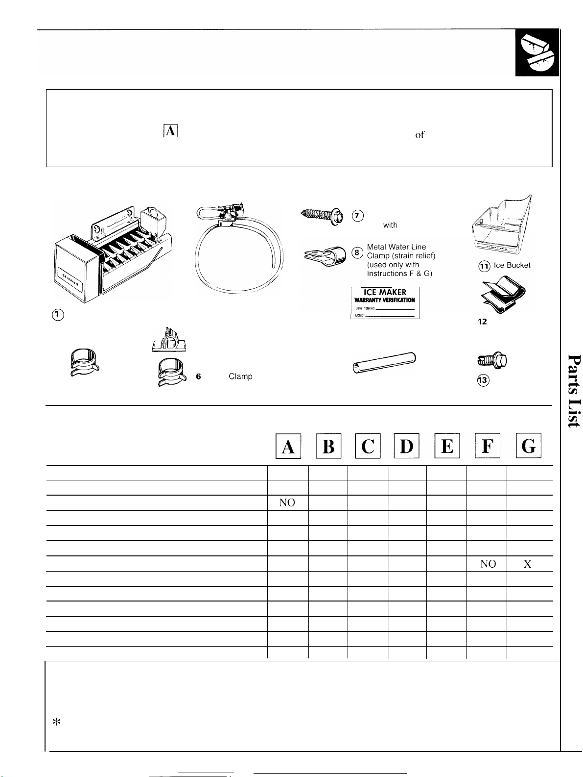
Contents Of Kit IM-2
Hex-Head Screw for Copper
@=f@Q)o
7 Water Line Clamp (used
with
only
Instruction G)
/l
A7
%*
,—
[
Y
v
I
Icemaker
o
2 Use and Care &
o
Installation Guide
B
3 Hose Clamp
o
(black)
!!iiii$
4 Water Valve Assembly
o
5 Adhesive-Backed
o
Water Line Fasteners
6
Hose Clamp
o
(not black)
v!!!~
9 Warranty Label
o
IO Fill Tube Extension
o
Use With Instruction Sheet
Parts List
1. Icemaker x
2. Use and Care & Installation Guide x x x x
3. Hose Clamp (black)
4. Water Valve Assembly
5. Adhesive-Backed Water Line Fasteners
6. Hose Clamp (not black)
7. Hex-Head Screw for Copper Water Line Clamp NO NO
8. Metal Water Line Clamp
9. Warranty Label
10.
Fill Tube Extension
11.
Ice Bucket
12.
Metal Water Line Clamp
13. Hex-Head Screw x
EHEHmEimmm
x
NTO
x x x
x
x x x x x
NO NO NO NO NO
x
x *
x *
x
NO
x x x
x x
x
x x x
x
NO
NO NO
x x
x x
x
12
Metal Water
0
Line Clamp
(strain relief)
3 Hex-Head
o
Screw
x x
x x
NO NO
x x
x x x
NO NO
x x
NO x
x x
x x
x
x
x x NO NO
x
x x
x
x
x
x x
NO x
x
x
x
x
x
OTHER PARTS YOU NEED...
Copper tubing, shut-off valve and fittings necessary to supply water to your refrigerator are not included in Kit IM-2.
You can purchase a complete water supply kit from your local dealer, or other parts center. Recommended water
supply kits are WX8X2, WX8X3 or WX8X4 depending on the amount of copper tubing you need.
*
For Instruction B only.. you will need a special bucket support and a different fill tube extension.
See the Install the Icemaker section for instruction ❑ .
5
Page 6
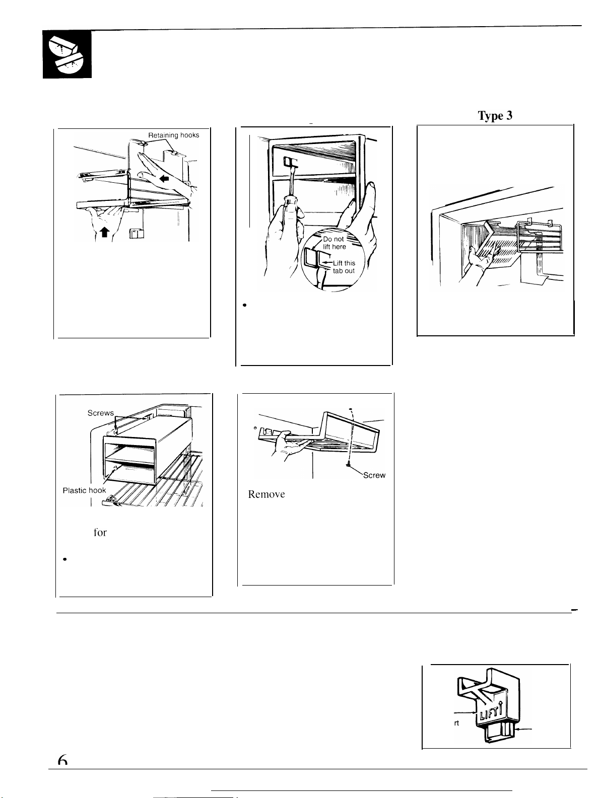
REMOVE EXISTING ICE TRAY HOLDER
Follow the instructions below for the ice tray holder that looks like yours.
Type 1
. Unhook the ice tray holder
side and bottom from the
retaining hooks. Lower the
holder until the side is clear of
the freezer shelf and remove it
from the freezer. You will not
need this part.
Type 4
Type 2
—
“
As you lift the tab on the left
side in the holder with the
blade of a screwdriver, pull
the holder forward and out.
You will not need this part.
Type 5
When following Instruction
G,
it is not necessary to remove the
ice tray shelf or, on some
models, the wire shelf next to it.
●
Tilt the ice tray holder and
remove it. You will not need
this part.
. Remove the 2 screws and save
them
for
installation of the
ice maker.
Q
Lift the ice tray holder off the
plastic hook. You will not
need this part.
REPOSITION FREEZER SHELF
You may need to reposition the
freezer shelf so the icemaker and
bucket sit properly.
●
Remo~7e
the screw with a
1/4” (6 mm) nutdriver.
● Pull the ice tray shelf away
from the wall. Remove the
shelf. You will not need
this part.
● Replace the screw.
To reposition the two piece shelf
supports: Slide the shelf up off the
base mount.
Shelf
support
—
r
@’~
L
Base
a
mount
Page 7
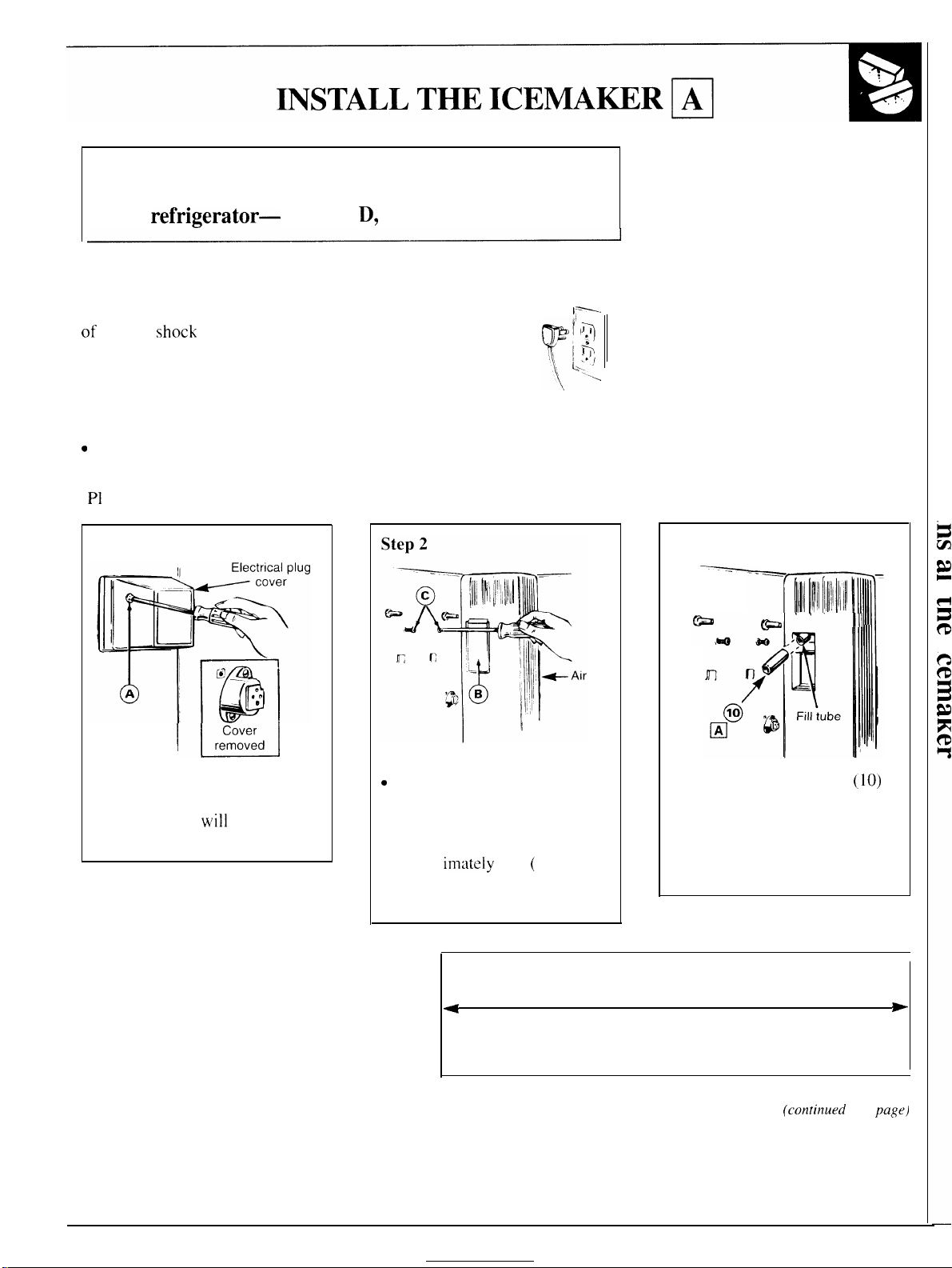
Is this the right instruction for your model?
Follow Installation indicated by the label on the back
of the
refrigerator—
A, B, C,
D,
E, F or G.
Installation Instructions
CAUTION: Unplug the Refrigerator.
of electric
refrigerator from its electrical outlet.
Read each step thoroughly before proceeding.
Tools needed:
● Phillips-type screwdriver
Q
Blade-type screwdriver
● Sharp knife
●
P1
iers
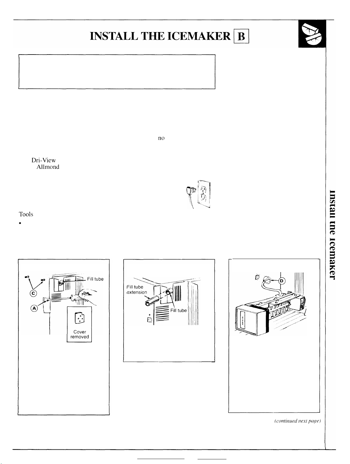
Step 1
shock
during installation, you must unplug the
To eliminate the danger
UE&d
Step 3
duct
● Remove the screw (A’) that
holds the electrical plug cover
in place. You
this screw and cover.
will
not need
“
Remove the plastic insert (B)
from the air duct and discard it.
. Loosen the two icemaker
mounting screws
approx
DO NOT REMOVE THESE
SCREWS.
irnately
4
(C)
1/2” ( 13 mm).
Cut the fill tube extension to this length for ❑
Cut the fill tube extension
the ❑ length (use the template
in this section) with a sharp
knife or single-edge razor blade
and slide it onto the fill tube
against the stop.
(conlinued next page)
(10)
to
*
7
Page 8
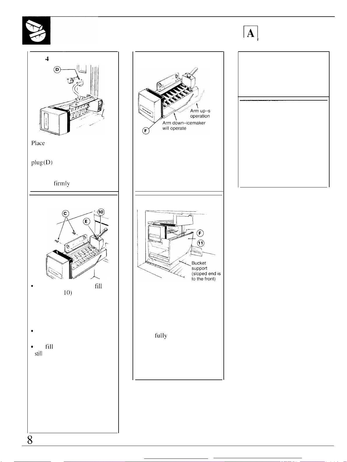
Step
INSTALL THE ICEMAKER
(continued)
4
Step 6
m
1
I
Step 8
A label (9) is provided in the kit
to record the date of installation
for warranty purposes. Apply it
to the back of the refrigerator.
Place
the icemaker in the freezer
compartment on its side as shown.
Insert the icemaker power cord
plug (D)
side wall, making sure the prongs
and holes are matched. Press
the plug
Step
into the socket on the
firmly
into the socket.
5
tops
The icemaker should feel secure
when you lift the icemaker
feeler arm (F) to the STOP (up)
position. Leave it there until the
refrigerator is connected to the
water supply to prevent
premature operation.
Step
7
Step 9
The warranty for the icemaker
is printed on the back page of
this booklet. Keep this booklet
with your Refrigerator Use &
Care Book.
The icemaker installation inside
the freezer compartment is now
complete. Continue to the
Installing the Water Valve
Assembly section.
“
Lift the icemaker so the
extension (
cup opening (E). Hang the
icemaker on the two mounting
screws (C).
Make sure:
“
The power cord plug is still
firmly in the socket.
“
The
fill
still
in the fill cup opening. (Check
the rear of the refrigerator to
make sure the fill tube has not
been pushed out of the back of
the refrigerator.)
. The icemaker mounting screws
are located in the uppermost
position of the mounting slots.
THEN TIGHTEN THE
ICEMAKER MOUNTING
SCREWS SECURELY.
10)
fits in the fill
tube extension ( 10) is
fdl
tube
Replace the freezer shelf.
Move the bucket support and
ice bucket (11 ) into place
directly under the icemaker.
See illustration.
NOTE: Check again to make
sure the icemaker power cord
plug is
socket with the prongs matched
to the corresponding holes.
Check again to make sure the
icemaker feeler arm (F) is in the
STOP (up) position.
fully
inserted into its
Page 9
Is this the right instruction for your model?
Follow Installation indicated by the label on the back
of the refrigerator—A, B, C, D, E, F or G.
Installation Instructions
Models that call for this instruction sheet need a bucket support and
different fill tube than is provided in this kit. This bucket support can
only be used on models with instruction B.
Obtain this bucket support and a fill tube extension at
requesting Pub. No. 2-1003 from:
General Electric Publications
c/o
Dri-View
4706 Allmond Ave.
Louisville, KY 40209
CAUTION: Unplug the Refrigerator. To eliminate the danger
of electric shock during installation, you must unplug the
refrigerator from its electrical outlet.
Read each step thoroughly before proceeding.
Tools
needed:
c
Phillips-type screwdriver
. Blade-type screwdriver
. Sharp knife
● Pliers
Manufacturing Co.
no
charge by
l-:
II7h
‘\
YL
\
ilq
-’]
Step 1
k.EE!_l
I
. Remove the screw (A) that
holds the electrical plug cover
in place. You will not need
this screw and cover.
. Loosen the two icemaker
mounting screws (C)
approximately 1/2” ( 13 mm).
DO NOT REMOVE THE
SCREWS.
Step 2
Take the fill tube extension from
the supplementary kit 2-1003
that you got by mail and slide it
onto the fill tube against the stop.
Step 3
Place the icemaker in the freezer
on its side as shown. Insert the
icemaker power cord plug (D)
into the socket on the side wall,
making sure the prongs and holes
are matched. Press the plug
firmly into the socket. When
inserted, the power cord plug
should fit flush to the freezer wall.
(corztinued tle.x-t
page)
9
Page 10

INSTALL THE ICEMAKER
4
Step
●
Lift the icemaker and position
the rear opening in the fill cup
(E)
over the fill tube extension.
Hang the
mounting screws (C).
Make sure:
“
The power cord plug is still
firmly in the socket.
“
The fill tube extension is still
in the fill cup opening. (Check the
rear of the refrigerator to make
sure the fill tube has not been
pushed out of the back of the
refrigerator. )
●
The icemaker mounting screws
are located in the uppermost
position of the mounting slots.
THEN TIGHTEN THE
ICEMAKER MOUNTING
SCREWS SECURELY.
icem~er
on the two
(continued)
Step
5
Arm down–icemaker
The icemaker should feel secure
when you lift the
feeler arm
position.
refrigerator is connected to the
water supply
premature operation.
Step
,—-—— —— :—
1 —-
p
Leave
6
, —
-—
~C+
L.-—
icemaker
(F)
to
{he
STOP (up)
it there until the
to
prevent
—
——._——————
~
‘<
——————.————
,-
–~
“~
&lll,
Ii
-
Ill
11’
~~~
‘
0
F;’
!, ?T:F
,\
,1
~’—-dl
l,,
~.. (
,,,a’<
.~~~~,”’
Replace the freezer shelf.
Move the bucket support and
ice bucket (11 ) into place
directly under the
See illustration.
NOTE: Check again to make
sure the icemaker power cord
plug is fully inserted into its
socket with the prongs matched
to the corresponding holes.
Check again to make sure the
icemaker feeler arm
STOP (up) position.
‘~
,L
Bucket
“J, support
,. (sloped end is
/’ t. the front)
icemakcr.
(F)
is in the
~
L
Step
7
A label (9) is provided in the kit
to record the date of installation
for warranty purposes. Apply it
to the back of the refrigerator.
Step
8
The
warrant~7
is printed on the back page of
this booklet. Keep this booklet
with your Refrigerator Use &
Care Book.
The icemaker installation inside
the freezer compartment is now
complete. Continue to the
Installing the Water Valve
Assembly section.
for the icemaker
Page 11

INSTALL THE ICEMAKER
Is this the right instruction for your model?
Follow Installation indicated by the label on the back
B,
C, D, E, F or G.
of the
refrigerator—
Installation Instructions
CAUTION: Unplug the Refrigerator.
of electric shock during installation, you must unplug the
refrigerator from its electrical outlet.
Read each step thoroughly before proceeding.
Tools needed:
. Phillips-type screwdriver
● Blade-type screwdriver
● Sharp knife
● Pliers
A,
To eliminate the danger
yr
,F-
,’
1,,,
\~
~
JI
:
7
fi
:+
J
“..
Step 1
t
.
(4’
A
0
@–
●
Remove the screw
the electrical plug cover in
place. You will not need this
screw and cover.
c
Remove the light shield insert
(B) and discard it.
“
Loosen the 2 screws (C)
approximately 1/2” (13 mm).
DO NOT REMOVE THESE
SCREWS.
(A)
that holds
Step 2
J
@
-a
.
.,6
@l
Cut the fill tube extension
to the ❑ length (use the
template in this section) with a
sharp knife or single-edge razor
blade and slide
tube against the stop.
4
it
onto the fill
Cut the fill tube extension to this length for
(10)
Step 3
Place the icemaker in the
freezer compartment on its side
as shown. Insert the icemaker
power cord plug (D) into the
socket on the side wall, making
sure the prongs and holes are
matched. Press the plug firmly
into the socket.
❑
.
*
(cmtirlued next
page)
H
Page 12

Step
INSTALL THE ICEMAKER
(continued)
4
Step 5
El
I
Step
1
7
A label (9) is provided in the kit
to record the date of installation
for warranty purposes. Apply it
to the back of the refrigerator.
●
Lift the icemaker so the fill tube
extension ( 10) fits in the fill cup
opening (E). Hang the icemaker
on the two mounting screws (C).
Make sure:
● The power cord plug is still
firmly in the socket.
● The fill tube extension ( 10) is
still in the fill cup opening. (Check
the rear of the refrigerator to
make sure the fill tube has not
been pushed out of the back of
the refrigerator. )
●
The icemaker mounting screws
are located in the uppermost
position of the mounting slots.
THEN TIGHTEN THE
ICEMAKER MOUNTING
SCREWS SECURELY.
tops
The
icemaher
when you
should feel secure
lift
the icemaker
feeler arm (F) to the STOP (up)
position. Leave it there until the
refrigerator is connected to the
water supply to prevent
premature operation.
Step
6
Step
8
The warranty for the icemaker
is printed on the back page of
this booklet. Keep this booklet
with your Refrigerator Use &
Care Book.
The icemaker installation inside
the freezer compartment is now
complete. Continue to the
Installing the Water Valve
Assembly section.
1
Put the ice bucket (11) directly
under the icemaker (to the left
and all the way to the rear of the
shelf under the icemaker).
NOTE: Check again to make
sure the icemaker power cord
plug is fully inserted into its
socket with the prongs matched
to the corresponding holes.
Check again to make sure the
icemaker feeler arm (F) is in the
STOP (up) position.
—
——
Page 13
INSTALL THE ICEMAKER
Is this the right instruction for your model?
Follow Installation indicated by the label on the back
of the
refrigerator—
A, B, C, D, E, F or G.
PI
Installation Instructions
CAUTION: Unplug the Refrigerator.
of electric shock during installation, you must unplug the
refrigerator from its electrical outlet.
Read each step thoroughly before proceeding.
Tools needed:
. Phillips-type screwdriver
. Blade-type screwdriver
. Sharp knife
. Pliers
Step 1
Electrical
\-
‘!
0
ii
plug cover
@
---
e
o
A
El
r
I
ee
e
J
Cover
removed
I
To eliminate the danger
Step 2
y[
Step 3
~.~.
~J I
<
T
~~:
\,,
Loosen the ~
mounting
screws (C).
Replace
them if you
removed
them when
taking out the ice tray tunnel.
These screws should extend
approximately 1/2” ( 13 mm)
out from the freezer wall.
Step
4
>
c
o
w
.
~-: --:-- II II
.:.
@
~:
-E
{
11 I
‘1!
Remove the screw (A) that
holds the electrical plug cover
in place. You will not need this
screw and cover.
Remove and discard the plate
(B) from the front of the air duct.
Cut the fill tube extension to this length for ❑
*
Cut the fill tube extension
(10)
to the ❑ length (use the
template in this section) with
sharp knife or single-edge razor
blade and slide it onto the fill
tube against the stop.
a
b
13
Page 14

INSTALL THE ICEMAKER
(continued)
~
Step
5
Place
the icemaker on its side
on the relocated shelf
Insert the icemaker power cord
plug
(D) into the socket on the
side wall, making sure the prongs
and holes are matched. Press the
plLlg
firmly into the socket.
Step
6
as
shown.
Step
7
d
Arm down–icemaker
will operate
F
d
The icemaker should feel secure
when you lift the icemaker
feeler arm (F) to the STOP (up)
position. Leave it there until the
refrigerator is connected to the
water supply to prevent
premature operation.
Step 8
Step 9
A label (9) is provided in the kit
to record the date of installation
for warranty purposes. Apply it
to the back of the refrigerator.
Step 10
The warranty for the icemaker
is printed on the back page of
this booklet. Keep this booklet
with your Refrigerator Use &
Care Book.
The icemaker installation inside
the freezer compartment is now
complete. Continue to the
Installing the Water Valve
Assembly section.
“
Lift the icemaker so the fill tube
extension ( 10) fits in the fill cup
opening (E),
on the two mounting screws (C).
.Make
sure:
“
The power cord plug is still
firmly in the socket.
● The fill tube extension (
still in the fill cup opening. (Check
the rear of the refrigerator to
make sure the fill tube has not
been pushed out of the back of
the refrigerator. )
. The icemaker mounting screws
are located in the uppermost
position of the mounting slots.
THEN TIGHTEN THE
ICEMAKER MOUNTING
SCREWS SECURELY.
Hang the icemaker
10)
is
14
Put the ice bucket ( 11)
directly under the icemaker.
See illustration.
NOTE: Check again to make
sure the icemaker power cord
plug is fully inserted into its
socket with the prongs matched
to the corresponding holes.
Check again to make sure the
icemaker
STOP (up) position.
feeler
arm (F) is in the
Page 15

INSTALL THE ICEMAKER
Is this the right instruction for your model?
Follow Installation indicated by the label on the back
of the refrigerator—A, B, C, D, E, F or G.
I
ml
Installation Instructions
CAUTION: Unplug the Refrigerator.
of electric shock during installation, you must unplug the
refrigerator from its electrical outlet.
Read each step thoroughly before proceeding.
Tools needed:
● Phillips-type screwdriver
. Blade-type screwdriver
. Sharp knife
● Pliers
Step 1
Electrical
1]
! I
plug cover
@—
d
Cover
removed
*L3
e
0
\
.
I
IT
[
A
‘i:~
Remove the screw (A) that
holds the electrical plug cover
in place. You will not need this
screw and cover.
To eliminate the danger
Step 2
~f$ifl!l
k%
If the grille (B) is not in place
so it louvers direct air to the
left, turn it as follows:
●
Remove the screw (B 1 ) which
holds
the
grille (B).
●
Remove
it 90°.
● Replace the screw and tighten.
the
B
grille
Bl-—’-
W
(B), rotate
Step 3
Loosen the mounting screws
but do not screw them all the way
out. These screws should extend
approximately 1/2” ( 13 mm) out
from the freezer wall.
Step
4
Remove and discard the white
plug from the upper left corner
of the freezer wall.
(C)
ve
Cut the fill tube extension to this length for
4
I
Cut the fill tube extension to this length for ❑
4
❑ LONG
P
I
SHORT
+
.
Page 16

INSTALL THE ICEMAKER
(continued)
El
Step
5
—.
F
‘
*X;
10
] E :
Cut
the fill tube extension
the ❑
SHORT
length (use the
template in this section)
rcfrige~”ator
feet
edge
the
~
template in
the extension
is 22.0 or 22. S cubic
with
a sharp
ra~f]r blade.
knife
otherwise use
LONG length (use the
this
section ~. Slide
on[o
the
or
fill
(10)
if
your
single-
tube
to
against the stop.
Step
6
Place the icemaker on its side
as shown. Insert the icemaker
power
socket on
cm-d plug
(D) into the
the
side wall, making
sure the prongs and holes are
matched. Press the plug firmly
into the socket.
Ste
.
Lift the icemaker so the fill tube
extension (10) fits in the
fill
cup
opening (E). Hang the icemaker
on
the
two
mounting screws (C).
Make sure:
c
The power cord plug is still
firmly
● The fill tube extension
still in the fill cup
in
the socket.
opening
( 10)
is
(Check
the rear of the refrigerator to
make sure the fill tube has not
been
pushed out of the back of
the refrigerator. )
c The
icemaker mounting screws
are located in
the
uppermost
position of the mounting slots.
THEN TIGHTEN THE
ICEMAKER MOUNTING
SCREWS SECURELY.
Step 8
tops
Step
9
---
,:~J”ly
/F
m
,~,
.–L:L
L
— - —— - —:—–—
PLlt
the ice bucket (11) directly
-1+
‘1 “
.’ w,,
,“,-
—
.
-————
~“F=
--
11
o
/
-
J.+=2J
]
under the icemaker on the shelf.
NOTE: Check again to make
sure the icemaker power cord
plug
is
fully
inserted into its
socket with the prongs matched
to the corresponding holes.
Check again to make sure the
icemaker feeler arm (F)
is
in the
STOP (up) position.
Step
10
A label (9) is provided in the kit
to record the date of installation
for warranty purposes. Apply it
to the back of the refrigerator.
Step 11
The warranty for the icemaker
is printed on the back page of
this booklet. Keep this booklet
with your Refrigerator Use &
Care Book.
The icemaker installation inside
the freezer compartment is now
complete. Continue to the
Installing the Water Valve
Assembly section.
16
The icemaker should feel secure
when you lift the icemaker
feeler arm (F) to the STOP (up)
position. Leave it there until the
refrigerator is connected to the
water supply to prevent
premature operation.
Page 17

INSTALLING THE
❑ mmllml
WATER
VALVE ASSEMBLY
CAUTION: Unplug the
Refrigerator. To eliminate ,=
the
danger
of electric
shock during installation,
you must unplug the
refrigerator from its electrical outlet
Read each step thoroughly
before proceeding.
Tools needed:
. Phillips-type screwdriver
. Blade-type screwdriver
. 5/ 16“ ( 8 mm)
. Sharp knife
● Pliers
Step 1
At the bottom
rear of the ‘---
refrigerator,
remove the
screw(s)
holding the
compressor ‘compartment cover (if covered)
and save them for reinstallation
later. Bend the cover
access to the compartment.
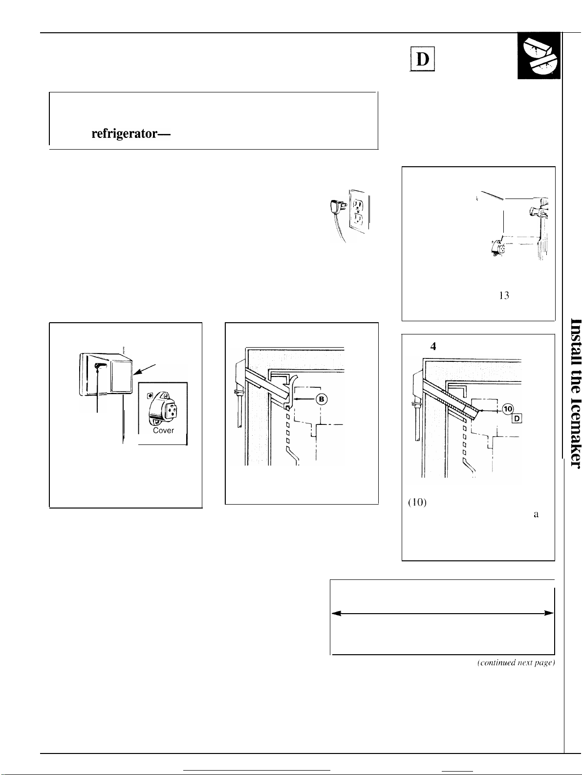
Step 2
● Locate the
female
connector
plug (A)
which is
attached to
the cabinet
by a wire tie. Remove the wire
tie and discard it.
. Remove
and discard
the tape
from the
female
connector
and plug ‘~ ~
onto the male terminals on the
water valve (4). Either wire
can
gO
Nutdri
a4 :-’
‘~-
“
-..-–
*4V
~
-.<> ‘“, :
T
$’
Ti
On
either terminal.
(cotltitlucd
ver
*
*-
%~~ ‘
- ~ % ,
“
‘~
back for
* Wire tie
%
. “,
‘h -
.
\ ‘A ,“ ,/
,,A
Ilt.vt
Y
..
=-
\ ~’ ~
.’
\
4
L <
I
\
.AA
.
~kJ' 1: ~
;1
J
‘
L:’!
\
—*
,,,, ‘
\
:Ik
cl)llitnn)
rl
~ ,1
“
~PJ’
\
Step
Step 2 (continued)
. Fasten the
water valve
to the
<
cabinet
edge
hole
(X) using
the
hex-
head screw (
.
DO NOT DRILL ANY
ADDITIONAL HOLES.
Step 3
G
Metal clamp is for copper tube in
~
house plumbing. Not to be used for
plastic tubing from the water valve.
● Push the metal clamp
(strain
lower flange of the cabinet
back directly in line with the
water valve.
. Check the plastic water line
nut on the bottom of the water
valve to be sure it is hand
tight. DO NOT USE TOOLS.
Step
4
c
tu
On models that have condenser
tubing on the back of the
cabinet, insert the plastic water
line between the tubing and the
back of the cabinet.
13)
from kit.
relie~ (12) onto the
5
the small
plastic cap
(B) from
the bottom
of the fill
tube inlet located in the
right
rear corner
refrigerator. Squeeze the ends
of
the hose clamp (6) from the
kit with pliers and slide the
clamp over the fill tube inlet.
While still squeezing the clamp.
insert the plastic water line into
the inlet & far as it will go
(approximately 1“ [25
Then slide the clamp
downward to capture the
plastic water line in place.
● Make sure the fill tube inlet is
aimed down.
Step
6
—
.3
(
r
.—~
5
LJ=
~
<’
/’4Rj
0
Adheswe-backed
Fasten the plastic water line to
the back of the cabinet with
adhesive-backed fasteners (5),
spacing the fasteners as shown
to take up the slack in the line.
Step
Refer to the water
instructions for connection to
home water supply. After the water
line installation is completed,
lower the icemaker feeler arm to
the ON (down) position.
The ice-making
begin until
freezer compartment reach
operating temperature, then
making will begin
fasteners for
7
the
J “
Fill
~;~; x
?-–g
&“
of the
.
—
line
installation
(>de will not
icemaker
cwtornaticallv
\
mm]].
—.—
r--
/
plastlc
and
6
Y?
u’pp;r-
)
water
Ilne
ice-
17
Page 18

INSTALL THE ICEMAKER
Is this the right instruction for your model?
Follow Installation indicated by the label on the back
of the
refrigerator—
A, B, C, D, E, F or
Installation Instructions
G.
~
1.
I
CAUTION: Unplug the Refrigerator. To eliminate the danger
of electric shock during installation, you must unplug the
refrigerator from its electrical outlet.
Read each step thoroughly before proceeding.
y~
{\
Tools needed:
. Phillips-type screwdriver
. Blade-type screwdriver
. Sharp knife
. P] iers
Step 1
Step 2
Remove the
electric plug cover.
To remove the type
shown in Fig. 1,
insert standard
_
b’
. .
.-
.
screwdriver blade
in slot at bottom of
cover, apply
Fig. 1
pressure upwards, and pry
cover away from freezer wall.
Discard this cover.
Loosen the two mounting screws
(A) but do not screw them all
the way out. The screws should
extend approximately 1/2” out
from the freezer wall.
To remove the
type shown in
Fig. 2, press
top of cover
down to free
its upper tab
from slot in
freezer wall.
Then pull
cover straight
out to free the
Fig. 2
lower tabs
from their slots. Save this cover
for reinstallation later.
~-~
/J~I
T
+,
:’1
\
k
I
;
Step 3
~
—-
●
Remove and discard the white
.
plug from the upper left corner
of the freezer wall.
●
Cut the fill tube extension (10)
to the ❑ length (use the
template in
this
section) with a
sharp knife or a single-edge
razor blade and slide it onto
the fill tube against the stop.
Cut the fill tube extension to this length for ❑
*
*
Page 19

Step4
Step
5
Step
7
. Remove the icemaker power
cord from the clip. Hold the
icemaker in the freezer
compartment as shown. Insert
the icemaker power cord plug
(B) into the socket on the rear
wall, making sure the prongs
and holes are matched. Press
the plug firmly into the socket.
. If the electric plug cover
removed in Step
1
is the one
shown in Fig. 2, reinstall it.
,1
L
1
1
1
Place the cover over the electric
plug with the icemaker power
cord running through the
bottom or side opening in the
cover, depending on the
orientation of the plug.
Next, put the lower tabs in the
slots on the freezer wall. Then
snap the upper tab into its slot.
IMPORTANT: This cover will
help keep the electric plug from
coming out
of the socket when
mounting the ice-maker. Be
sure to reinstall it now.
●
Lift the icemaker so the fill tube
extension ( 10) fits in the fill cup
opening (C). Hang the icemaker
on the two mounting screws (A).
Make sure:
● The power cord plug is still
firmly in the socket.
. The fill tube extension
(
10) is
still in the fill cup opening. (Check
the rear of the refrigerator to
make sure the fill tube has not
been pushed out of the back of
the refrigerator.)
●
The icemaker mounting screws
are located in the uppermost
position of the mounting slots.
THEN TIGHTEN THE
ICEMAKER MOUNTING
SCREWS SECURELY.
Step 6
tops
The icemaker should feel secure
when
you
lift the icemaker
feeler arm
(D)
to the STOP (up)
position. Leave it there until the
refrigerator is connected to the
water supply to prevent
premature operation.
Position the freezer shelf for
ice-making and move the ice
bucket (11 ) into place on the
shelf under the icemaker.
The straight 2-position shelf
should be in the lower position.
The step shelf’s lower step
should be under the icemaker.
The cantilever shelf top hooks
should be in the 6th slot up
from the bottom of the track.
NOTE: Check again to make
sure the
icemake; power cord
plug is fully inserted into its
socket with the prongs matched
to the corresponding holes.
Check again to make sure the
icemaker feeler arm (D) is in
the STOP (up) position.
Step 8
A label (9) is provided in the kit
to record the date of installation
for warranty purposes.
Appl>~
it
to the back of the refrigerator.
Step
9
The warranty for the icemaker
is printed on the back page of
this booklet. Keep this booklet
with your Refrigerator Use &
Care Book.
The icemaker installation inside
the freezer compartment is now
complete. Continue to the
Installing the Water Valve
Assembly section.
19
Page 20

INSTALLING THE WATER VALVE ASSEMBLY
~1
CAUTION: Unplug the
Refrigerator.
To eliminate
the danger of electric
shock during installation, i
i .5
y[
,-
i IN
7
~
you must unplug the
refrigerator from its electrical outlet.
Read each step thoroughly
before proceeding.
Tools needed:
●
Phillips-type screwdriver
●
Blade-type screwdriver
. 1/4” (6 mm) Nutdriver
● Sharp knife
● Pliers
Step 1
At the bottom
rear of the
refrigerator,
remove the
screw(s)
holding the
compressor
0
4
~~,= & .&’
~~ ~ ~ I
s-- ~-
= ~ ~=.
-Z ~
--
2
Q,
--e
m
.-
compartment cover and save
them for reinstallation later.
Bend the cover back for access
to the compartment.
Step 2
. Locate the Me
female
connector
plug
(c)
which is
attached to
the cabinet
by a metal or plastic clip.
Remove the clip by removing
the screw. Save the screw for
mounting the water valve
later. Discard the clip.
●
Plug the
femal
connector (C)
onto the male
terminals on
the water
valve (4).
Either wire
can
go
on either terminal.
(continued next column)
Step 2 (continued)
● Fasten the
head screw that you removed
at the beginning of Step 2.
DO NOT DRILL ANY
ADDITIONAL HOLES.
. Check the plastic water line
nut on the bottom of water
valve to be sure it is hand
tight. DO NOT USE TOOLS.
Step 3
Screw
/4
@
8
ml
A#g\
g&J?/~
Attach the water line clamp
●
/r
/
/
/“
/
/’ /
/
(8) from the kit to the
refrigerator for safekeeping
until you connect the house
water line to the icemaker
water valve (see the Water
Line Installation Instructions).
Drive one of the screws,
removed in Step 1, into the
cabinet edge through the clamp
and hole in compressor cover.
. Before the icemaker is
operated, the water line clamp
(8) must attach the copper line
to the refrigerator to help
avoid undue wear on the
tubing that might cause leaks.
Step
4
. Remove
the small
plastic cap
(D)
from
the bottom
of the fill
tube inlet located in the
Fill
~;~; x
9
&
D
Xl
x’
6
o
,
u’pper-
~
right rear corner of the
refrigerator. Squeeze the ends
of the hose clamp
(6)
from the
kit with pliers and slide the
clamp over the fill tube inlet.
While still squeezing the clamp,
insert the plastic water line into
the inlet as far as it will
go
(approximately 1“ [25 mm]).
Then slide the clamp
downward to capture the
plastic water line in place.
. Make sure the fill tube inlet is
b
aimed down.
Step
5
Fasten the
plastic water
line to the
back of the
cabinet with
adhesive-
backed
fasteners
(5), spacing
the fasteners
as
shown to
take up the
AdheSIVe-baCked
for
plashc
fasteners
water hne
slack in the line.
Step 6
Refer to the water line installation
instructions for connection to
home water supply. After the water
line installation is completed,
lower the icemaker feeler arm
to the ON (down) position.
The ice-making
begin
until the icemaker and
q’cle
will not
freezer compartment reach
operating temperature, then
making
will
begin automatically.
ice-
20
Page 21

INSTALL THE ICEMAKER
Is this the right instruction for your model?
Follow Installation indicated by the label on the back
of the refrigerator—A9 B, C, D, E, F or
Installation Instructions
(2.
❑
CAUTION: Unplug the Refrigerator.
of electric shock during installation, you must unplug the
refrigerator from its electrical outlet.
Read each step thoroughly before proceeding.
Tools needed:
● Phillips-type screwdriver
● Blade-type screwdriver
● Sharp knife
● Pliers
Step 1
Remove the electric
~eft-side
discard it.
Pull the cover (A)
straight out while
pressing the sides
of the cover to
free its tabs from
the slots in the freezer wall.
wall and
To eliminate the danger
Step 2
B
v
1
.,
I
@
Loosen the two mounting
screws
them all the way out. The screws
should extend approximately
1/2” (13 mm) out from the
freezer wall.
(B)
but do not screw
‘g
~
fo
Step 3
● Remove and discard the white
plug from the upper left corner
of the freezer wall.
● Cut the fill tube extension (10)
to the ❑ length (use the
template in this section) with a
sharp knife or single-edge
razor blade and slide it onto
the fill tube against the stop.
Cut
the fill tube extension to this length for ❑ .
*
+
Page 22

INSTALL THE ICEMAKER
Step
4
.
Remove
cord from the clip. Place the
icemaker on its side
Insert the icemaker power cord
P]ug (C)
side wall, making sure the prongs
and
plug firmly into the socket.
the icemaker power
as
shown.
into the socket on the
holes are matched. Press the
(continued)
Step 6
J’
Arm down–icemaker
E
7’
The icemaker should feel secure
when you lift the icemaker
feeler arm
position. Leave it there until the
refrigerator is connected to the
water supply to prevent
premature operation.
will operate
(E)
to the STOP (up)
~
Step
8
A label (9) is provided in the kit
to record the date of installation
for warranty purposes. Apply it
to the back
Step
The warranty for the icemaker
is printed on the back page of
this booklet. Keep this booklet
with your Refrigerator Use &
Care Book.
The icemaker installation inside
the freezer compartment is now
complete. Continue to the
installing the Water Valve
Assembly section.
of the refrigerator.
9
Step 5
● Lift the icemaker so the
extension (
opening (D). Hang the icemaker
on the 2 screws (B).
Make sure:
“
The power cord is still firmly
in the socket.
● The fill tube extension ( 10) is
still in the
(Check the rear of the refrigerator
to make sure the fill tube has
not been pushed out of the
back of the refrigerator.)
● The icemaker mounting screws
are located in the uppermost
position of the mounting slots.
THEN TIGHTEN THE
ICEMAKER MOUNTING
SCREWS SECURELY.
10)
fits the fill cup
fill
cup opening.
fdl
tube
Step
7
Move the ice bucket (11 ) into
place under the icemaker.
NOTE: Check again to make
sure the icemaker power cord
plug is firmly inserted into its
socket with the prongs matched
to the corresponding holes.
Check again to make sure the
icemaker feeler arm (E) is in the
STOP (up) position.
22
—
—-
Page 23

INSTALLING THE WATER VALVE ASSEMBLY
~]
CAUTION: Unplug the
Refrigerator.
To
eliminate ~,
the danger of electric
shock during installation,
y[
F--
):1
Tl
h
L.’ I
‘ - .x
you must unplug the
refrigerator from its electrical outlet.
Read each step thoroughly
before proceeding.
Tools needed:
. Blade-type screwdriver
c
Pliers
● 1/4”
(6
mm) and
5/1 6“ (8 mm) Nutdriver
. Sharp knife
Step 1
At the bottom ---- -- –
rear of the
-—&’
l-l
refrigerator,
remove the
screw(s)
holding the
zrF—
compressor
——
compartment cover and save
them for reinstallation later.
Bend the cover back for access
to the compartment.
Step 2
● Locate the female connector
plug (B).
● Plug the female connector (B)
onto the male terminals on the
water valve (4). Either wire
can go on either terminal.
(continued
ne.yt
column)
Step 2 (continued)
● Fasten the water valve to the
cabinet by driving the hex-head
screw (
13)
from the kit into
the hole (X) in the cabinet leg.
● Check the plastic water line
nut on the bottom of the water
valve to be sure it is hand
tight. DO NOT USE TOOLS.
Step 3
-; &
~
7
gb
, ,
8
.
Attach the water
line clamp
(8)
from the kit to
the refrigerator
for safekeeping
m
until you
m
connect the
%
~
a
house water line to the icemaker
water valve (see the Water
Line Installation Instructions).
With the clamp directly in line
with the water valve, drive the
screw (7) from the kit through
the clamp (8) at indent into the
back of the cabinet.
s
Before the icemaker is operated,
the clamp must attach the copper
water line to the refrigerator to
help avoid undue wear on the
tubing that might cause leaks.
Step
4
. Remove
the small
Fill
3 or@
plastic cap t~b~ ,>
(C)
from
the bottom
of the
tube inlet
Inlet
“xi
c
fill
(Appearance , “
Q
‘ayvaW)
located in the upper-right rear
corner of the refrigerator.
(continued next column)
Step 4
(continued)
. Squeeze the ends of the hose
clamp (3) or (6) from the kit
with pliers and slide the clamp
over the fill tube inlet. (Use
the black clamp with the black
fill tube inlet, use the other
clamp with the other fill tube
inlet. ) While still squeezing
the clamp, insert the plastic
water line into the inlet as far
as it will go (approximately 1”
[25 mm]). Then slide the
clamp downward to capture
the plastic water line in place.
s
Make sure the fill tube inlet is
aimed down.
Step
5
Fasten the
plastic
water line to
the back of
the cabinet
with
adhesive-
backed
fasteners
(5), spacing
the fasteners
as shown to
take up slack
“--=-’
Adheswe-backed fasteners
for
plastic
water Ime
in the line.
Step 6
Refer to the water line
installation instructions for
connection to home water
supply. After the water line
installation is completed, lower
the icemaker feeler arm to the
ON (down) position.
The ice-making cycle will
not begin until the icemaker
and freezer compartment
reach
operating temperature,
then ice-making will begin
automatically.
23
—
Page 24

Water Line
Installation Instruction
CAUTION:
●
If
you use your refrigerator before connecting
the water line, make sure the icemaker feeler
arm
1s
kept m the STOP (up) position.
c
Do not install the icemaker tubing in areas
where temperatures fall below freezing.
s
When using any electrical device (such as a
power drill) during installation, be sure the
device is insulated or wired in a manner to
prevent the hazard of electric shock.
● All installations must be in accordance with
local plumbing code requirements.
WHAT YOU WILL NEED
c
A
cold
water supply is required for automatic
icemaker operation. The water pressure must
be between 20 and 120
●
Power drill,
● Copper tubing, 1/4” (6 mm) outer diameter
to connect the refrigerator to the water supply.
Be sure both ends of the tubing are cut square.
To determine how much copper tubing you
need: measure the distance from the water valve
on the back of the refrigerator to the water
supply pipe. Then add 8 feet (244 cm). Be sure
there is sufficient extra tubing (about 8 feet
[244 cm] coiled into 3 turns of about 10 inches
[25 cm] diameter) to allow the refrigerator to
move out from the wall after installation. Do not
use plastic tubing or plastic fittings because the
water supply line is under pressure at all times.
Also, certain types of plastic tubing may become
brittle with age and crack, resulting in water
leakage.
c
Shutoff valve to connect to the cold water
line. The shut-off valve should have a water
inlet with a minimum inside diameter of 5/32”
(4 mm) at the point of connection to the COLD
WATER LINE. Saddle-type shut-off valves are
included in many water supply kits. Before
purchasing, make sure a saddle-type valve
complies with your local plumbing codes.
● Two 1/4” (6 mm) outer diameter compression
nuts and 2 ferrules (sleeves) – to connect
the copper tubing to the shutoff valve and the
refrigerator water valve.
● If your existing water line has a flared fitting at
the end, you will need an adapter (available at
plumbing supply stores) to connect the water
line to the refrigerator OR - you can cut off the
flared fitting with a tube cutter and then use a
compression fitting.
unless you have a self-piercing valve.
p.s.i.
WARRANTY INFORMATION
This water line installation is not warranted by
the refrigerator or icemaker manufacturer.
Follow these instructions
the risk of expensive water damage.
❑
SHUT OFF THE MAIN WATER SUPPLY.
Turn on the nearest faucet long enough to clear
the line of water.
(
❑
INSTALL THE SHUTOFF VALVE ON THE
NEAREST FREQUENTLY USED DRINKING
WATER
Typical ways to connect to water supply
~
Through floor
to basement
cold
a. Choose a location for the valve that is easily
b. Drill a 1/4” (6 mm) hole in the water pipe, using
c. Fasten the shutoff
d. Tighten the clamp
LIME.
a
Under sink
to cold
water pipe
accessible. It is best to connect into the side of
a vertical water pipe.
connect into a horizontal water pipe, make the
connection to the top or side, rather than at
the bottom, to avoid drawing off any sediment
from the water pipe.
a sharp bit. Remove any burrs resulting from
drilling the hole in the pipe. (Do not drill a
hole if the valve is a self-piercing type.)
valve to the cold
water pipe with the
pipe clamp.
screws until the
sealing washer
begins to swell. Do
not over-tighten or
you may crush the
copper tubing.
water pipe water pipe
carefdly
~~
Through wall to
utdlty
room cold
When it is necessary to
to minimize
jj)-l=
In crawl
space under
house
Vertical
cold water
pipe
+
t
24
—
Page 25

❑
ROUTE THE COPPER TUBING BETWEEN THE
COLD WATER LINE
Route the tubing through a hole drilled in the
floor or wall (behind the refrigerator or adjacent
base cabinet) as close to the wall as possible. Be
sure there is sufficient extra tubing (about 8 feet
[244 cm] coiled into 3 turns of about 10” [25 cm]
diameter) to allow the refrigerator to move out
from the wall after installation.
❑
CONNECT THE COPPER TUBING TO THE
SHUTOFF VALVE.
Place the compression
nut and ferrule (sleeve)
onto the end of
and connect it to the
shutoff valve. Make sure
the tubing is fully
inserted into the valve.
Tighten the compression
nut securely.
the tubing
AND THE REFRIGERATOR.
Remove the plastic flexible cap from the
a.
water valve.
Place the
b.
compression nut
and ferrule (sleeve)
onto the end of the
tubing as shown.
Insert the end of
c.
the copper tubing
into the water
valve connection
as far as possible.
While holdin~
the tubing, tighten the
d. Fasten the copper tubing into the clamp
provided to hold it in a vertical position. You
may need to pry open the clamp.
~
TURN THE WATER ON AT THE
SHUTOFF VALVE.
Tighten any connections that leak.
1/4” (6 mm) Tubing
Copper tubing
c.
fitting.
clamp
Refrlger:~tor conne~tlon
I
❑
TURN ON THE WATER AND FLUSH OUT
THE TUBING.
a. Turn the main water supply on and flush out
the tubing until the water is clear.
b. Shut the
about one quart of water has been flushed
through the tubing.
❑
CONNECT THE COPPER TUBING TO
THE REFRIGERATOR.
Before making the connection to the
refrigerator, be sure the refrigerator power
cord is not plugged into the wall outlet.
We recommend installing a water filter
(available at service and parts centers) if your
water supply has sand or particles that could
clog the screen of the refrigerator’s water valve.
Install it in the water line near the refrigerator.
water
off at the water valve after
@-l
PLUG THE REFRIGERATOR POWER CORD
INTO A GROUNDED ELECTRICAL OUTLET.
~
SET THE ICEMAKER FEELER ARM TO THE ON
(DOWN) POSITION.
The icemaker
reaches its operating temperature of 15° 1? (-9 C.)
or below. It will then begin operation automatically
if the icemaker is in the ON (down) position.
NOTJ3:
first starts, causing some water spillage from the
icemaker into the ice bucket. This is normal and
should not happen again. The first few batches of
cubes should be thrown away, so that remaining
impurities in the water line will be flushed out.
!!!
THE WALL.
Arrange the coil of copper tubing so that it does
not vibrate against the back of the refrigerator or
against the wall.
The icemaker may double-cycle when it
MOVE THE REFRIGERATOR BACK TO
will
not begin to operate until
it
—
25
Page 26
o
/
din
With the purchase
information or assistance
of
your new GE appliance, receive the assurance that if you ever need
We’ll Be There
f~-om
GE, we’ll be there. All you have to do is call-or write!
In-Home Repair Service
.\ (
;E. c{)niunlcr ~c>r~icc
(k)lls~lnlt’r
~~(>(kd:~ts, !):()()
lx’ ll:indl(’d in
Ser\ict> [t)rllp~~ll>-{)pcrated
a.nl. to
jllst ont” \fisit.
In Canada consult
prt)fkssiotlal will
2:()()
p.m.
Saturda)s).
prmidc
locations
yourlocaltelephone lh’’ectoryforthe
In the UnitedStates:80&GEXARES
expert repair service, scheduled at a time that’s convenient for you. Many GE
offervou
OUI-
f’actor~-trained technicians know your appliance inside and out-so most repairs can
ser~ice today or tomorrow, or at your convenience
Center nearest you.
GEAnswer Center@
\\’l]:ittxtr J
\ ( )1]
(la\ , 7 da\\ :i
In Canada contact
r (llle
()~lr
question about
~(i( )] E—— \\rill
uc(’k.
be answered
Managec
In the UnitedStates:80L1626.2000
any GE
rmjor
prompt]}
appliance,
and courteously’.
(;E
Consumer Relations, Cameo, Inc., 2645 SkymarkAvenue,
Mississauga, Ontario, Canada L4W4H2
kr
Customers With Special Needs...
[ ‘pO1~ 1 (’(]~l(st. (;E will
fol pc>lsom ~tith
;L)ll\ui~lc’r\ with
(
(S()()-833-
1322) to request infornlation or
pro~ide Braille controls fbr a ~miety of GE appliances, and a brochure to assist in planning a barrier-free kitchen
limited
mobiliq.
impaired hearing or speech who have access to a TDD or a conventional teletypewriter may call 800-TDD-GEAC
‘ro obtain these items, free of charge, call 800.626.2000.
ser}ice.
Answer (;enter~
Anci
you can call
In the United States:801Z626.2000
(80&M32-2737)
(7:00
a.m. to 7:00 p.m.
Cameo Service
inf{~rmaticm
an~’
service is available to help. Your call–and
time. GE Answer Center@ service is open 24 hours a
orAutiorikedService
In Canada contact
tlfanage~
Consumer Relations, Cameo, Inc., 2645 SkymarkAvenue,
Mississauga, Ontario, Canada L4W4H2
Service
Ji )L] ~.in
Ill\ c
\ ( )Llr ~iarr.int~ ii
t(xla~’i
pric(’~.
801146136361n
/?arts andAccessories
Individuals qualified to service their own appliances can have needed parts or accessories sent directly to their home. The GE parts
i~~tel]l pr(nides
L .ll d~
,lre accepted.
User maintenance instructions contained in this booklet cover procedures intended to be performed by any user. Other servicing
generally should be referred to qualified service personnel. Caution must be exercised, since improper servicing may cause unsafe
operation.
contracts
tl~c
secure fiwling that GE
still in
efl’ect ancl >wu’11 recei~.e
Canada
access to
(Nwr
47,()()0
In the United States:80L1626-2224
(l)nsumel-
In the
parts . . .
Ser\ice will still be there after your warranty expires. Purchase a GE contract while
a substantial discount.
W’ith
a multiple-year contract, you’re assured of future service at
UnitedStates:800-626-2002
and all
C~E
Genuine Renewal Parts are fully warranted. VISA, MasterCard and Discover
In Canada consult your local telephone directory for the Cameo Service or Authorized Service
Center nearest you.
26
Page 27

Page 28

lb
II
II
YOUR AUTOMATIC ICEMAKER
WARRANTY
Staple sales slip or
cancelled
here. Proof of original purchase date
is needed to obtain service
1
under warranty.
,1
check
I
1
WHAT IS COVERED
WHAT IS NOT COVERED
FULL ONE-YEAR WARRANTY
For one year from date of original
purchase, we will provide, free of
charge,
your home to repair or replace
any part of the automatic
icemaker that fails because of a
manufacturing defect.
● Service trips to your home to
Read your Use and Care material.
If you then have any questions
about operating the
please contact your dealer or our
Consumer Affairs office at the
address below, or call, toll free:
GE Answer
800.626.2000
consumer information service
. Improper installation.
If you have an installation problem,
contact your dealer or installer.
parts and service labor in
teach you how to use the
product.
-
product,
Cente@
This warranty is extended to
the original purchaser and any
succeeding
purchased for ordinary home use
in the 48 mainland states, Hawaii
and Washington,
warranty is the same except that it
is LIMITED because you must pay
to ship the product to the service
shop or
travel costs to your home.
All warranty service will be
provided by our Factory Service
Centers or by our authorized
Customer
normal working hours.
Call I-800-GE-CARES
(1-800-432-2737).
You are responsible for providing
adequate electrical, plumbing and
other connecting facilities, including
the water line to the icemaker and
the water line installation.
●
Replacement of house fuses or
resetting of circuit breakers.
●
Failure of the product if it is used
for other than its intended purpose
or used commercially.
●
Damage to product caused
by accident, fire, floods or acts
of God.
WARRANTOR IS NOTRESPONSIBLE
FOR CONSEQUENTIAL DAMAGES.
owner for products
D.C.
In Alaska the
for”the
service technician’s
Care@
servicers during
Some states do not allow the exclusion or limitation of incidental or consequential damages, so the above limitation or exclusion
may not apply to you. This warranty gives you specific legal rights, and you may also have other rights which vary from state to state.
To know what your legal rights are in your state, consult your local or state consumer affairs office or your state’s Attorney General.
Warrantor: General Electric Company
If further help is needed concerning this warranty, write:
Manager—Consumer Affairs, GE Appliances, Louisville, KY 40225
E&E&n_l
12-93 CG
IM-2
Printed in the United States
 Loading...