

GE TruVision DVR 10, TVR 10 Quick Start Manual

GE
Security
TruVision DVR 10 Quick Start Guide
Content
Contact information 1
Package contents 1
Installation environment 1
Setting up the TVR 10 1
Connecting the devices 1
Turning on the TVR 10 2
Operating the TVR 10 2
Live mode 4
Overview of the main menu 4
Logging on 5
Turning off the TVR 10 5
Troubleshooting 5
Battery removal 5
TVR 10 screen map 6
Contact information
For contact information see our Web site:
www.gesecurity.com.
Installation environment
Refer to the user manual for detailed information, but
observe these important requirements:
• Place the TVR 10 in a secure location.
• Ensure that the TVR 10 is in a well-ventilated area.
• Do not expose the unit to rain or moisture.
Setting up the TVR 10
To quickly put the TVR 10 into operation:
1. Connect all the devices required to the back panel of
the TVR 10. See
2. Turn on the unit using the power switch on the back
panel. After running automatic diagnostic tests on the
devices, the TVR 10 displays video images on-screen.
3. Press the Menu button on the front panel to access the
main menu. The log on screen appears.
4. Enter the default user ID and password.
Figure 1 on page 2.
Package contents
The TruVision DVR 10 (model TVR 10) is shipped with the
following items:
• TruVision DVR 10
• IR (infrared) remote control
• Two AAA batteries
• USB mouse
• Power supply
• AC power cord
• TruVision DVR 10 Quick Start Guide
• TruVision DVR 10 User Manual (on CD)
© 2009 GE Security, Inc. P/N 1068259 • REV A • ISS 06JUL09
User ID: admin
Password: 1234
The main menu screen appears.
5. Modify the TVR 10 preconfigured settings as required,
using the various dialog screens. (See “
map
” on page 6.)
6. When customization is complete, press ESC to exit to
the main menu and return to live mode.
TVR 10 screen
Connecting the devices
Use Figure 1 on page 2 as a visual guide to connect the
various peripherals to the TVR 10.
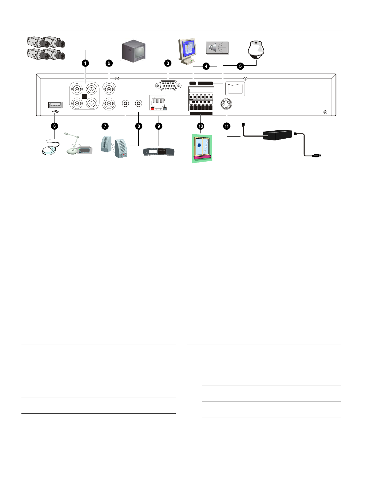
Figure 1: TVR 10 back panel connection diagram
13
42
VIN VOUT
1
2
AIN AOUT
Link/Act
100
FD/Col
Power
12345678
ETHERNET
1. Connect up to four cameras
2. Connect up to two CCTV monitors (one for main, two for spot)
3. Connect to a VGA monitor
4. Alarm output
5. Connect to a PTZ control
6. Connect to a USB mouse
VGA
RS-485
T+T-R+R-1 G
OUT
ALARM IN
1234GG
7. Connect to audio input
8. Connect to speakers
+12V
9. Connect to network devices
10. Connect to alarm input cables
11. Connect to the power supply
POWER
Turning on the TVR 10
Turn on the TVR 10 using the power switch on the back
panel. When you turn on the device, the TVR 10
automatically displays all live views from the connected
cameras. It also automatically begins recording.
Operating the TVR 10
LED indicators
The LED indicators on the front panel light up or flash to
alert you to various conditions.
Table 1: LED indicator descriptions
LED Description
Power Steady green: The TVR 10 is powered up with no
error conditions.
HDD Blinking red: Video is being recorded onto the hard
drive.
Solid red: The hard drive has an error.
Tx/Rx Blinking green: Network data is being transferred to
or from the TVR 10.
Control options
There are several ways to control the TVR 10:
• Front panel control
• IR remote control
• Mouse menu control
• Web browser control
Tip: A full range of alphanumeric characters is only
available when using the mouse or remote control.
Front panel control
The buttons on the front panel control most functions. See
Figure 3 on page 3 for locations of the controls.
Table 2: Front panel control descriptions
Item Control Description
1 Status LEDs Show the TVR 10 status. See Table 1 above.
2 Numeric buttons Switch camera views and input numbers.
MENU Accesses the main menu.
DISP Displays multiscreen live mode. Accesses live
mode.
SRCH Displays the Play Back screen for video
playback.
PTZ Accesses the PTZ control mode.
LIVE Displays Camera 1 in live mode.
REC Displays the Manual Record screen.
2 TruVision DVR 10 Quick Start Guide
 Loading...