

Page 1
GE Oil & Gas
Turboexpander-generators
Page 2
Turboexpandergenerators
A turboexpander expands process fluid
from the inlet pressure to the discharge
pressure in two steps: first through variable
inlet guide vanes and then through the
radial wheel. As the accelerated process
fluid moves from the inlet guide vanes
to the expander wheel, kinetic energy is
converted into useful mechanical energy
– extracting energy from the process
fluid and cooling it down. The mechanical
energy is available to drive other process
equipment – in this case, a generator.
Our turboexpander-generator designs
respond to specific industry needs for
increased capacity, reduced costs and
maximized reliability in a wide range of
applications, including:
Continually expanding capabilities
After more than 50 years of turboexpander design, GE now
has about 1,200 units operating worldwide (over 150 coupled
with generators) – and a proven record of delivering higher
power levels, performing at extreme operating temperatures
and achieving greater pressure ratios.
This success across the natural gas and hydrocarbon
industries is a result of our continuous improvement in areas
such as rotor and bearing design, efficiency optimization and
control systems.
• Oil & Gas processing Natural Gas Liquids
(NGL) plants, Liquefied Petroleum Gas
(LPG) recovery; tail gas treatment; GasTo-liquids (GTL); Integrated Gasification
Combined Cycle (IGCC)
• Liquefaction and purification of gases on
air treatment plants
• Petrochemicals: hydrogen, nitrogen
and ammonia purification; ethylene
production
• Pressure Let Down (PLD) on pipeline
• Geothermal power generation
(e.g. Organic Rankine Cycle, Kalina and
direct steam)
• Waste-heat recovery (WHR) and
Combined Heat and Power (CHP)
• Ocean Thermal Energy Recovery (OTEC)
Page 3

Excellence in design and testing
Construction Modifications and Uprates
The GE Turboexpander Center of Excellence brings together
GE specialists in design, manufacturing and testing to ensure
continuous innovation of application-specific solutions.
We work in close cooperation with customer engineering and
plant operation teams – and are therefore highly attuned to the
challenges they face every day. In-depth performance data
and myriad operating insights are continually fed back into our
engineering processes so that our designs are always on the
leading edge.
Our advanced testing facilities are completely
equipped with real-time data acquisition systems
and integrated analysis tools to provide a complete
map of equipment performance. Our capabilities
include tests and inclusion of feed gas preparation
systems – for tests with virtually any gas mixture
of interest to a customer. We also have the
ability to perform full-load string tests with up- or
downstream compressors.
GE turboexpander-generators are normally tested
with low-pressure air in an open loop setup in
accordance with ASME PTC10, Type 2.
Our Global Services teams provide a comprehensive range of
specialized solutions designed to maximize plant productivity and
return on investment.
We develop customized solutions for every installation and
application. Whether your goal is to economically modify
your process or to inject the latest technologies for increased
productivity with minimal downtime, our approach typically
minimizes impact on the turboexpander installation and piping.
From engineering design to on-site installation, all work is
performed to the highest standards by GE-trained specialists,
with full support for the entire process provided by our network of
facilities and resources.
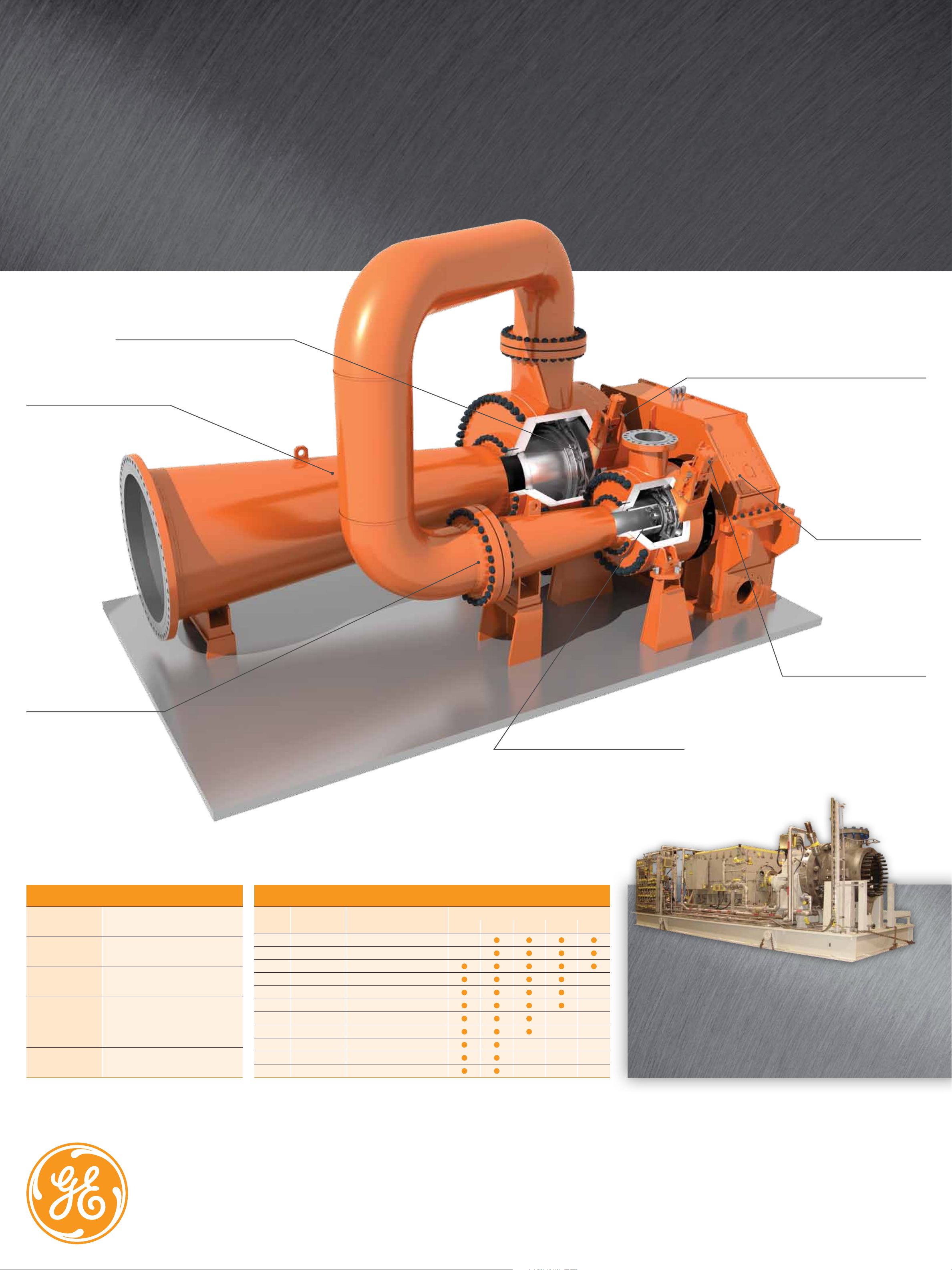
Technologies
for extreme challenges
Page 4
GE Oil & Gas
Turboexpander-generators
With design features to increase performance and reduce
maintenance downtime in extreme natural gas applications
Patented multi-link Inlet Guide Vanes (IGVs)
for precise control and smooth adjustment.
High-efficiency aerodynamics
customized to customer specifications.
Dynamic dry gas seals can be applied in single, double or
tandem configurations to minimize buffer gas leakage.
High pressure ratios or high
flow rates require multistage
arrangement. GE expanders can
accommodate up to four stages
on a common integral gearbox.
The expander wheels are
mounted directly on the
high-speed pinions, and
the generator is coupled
to the low-speed gear.
Hydraulic, pneumatic or electric
actuators control the IGVs and
provide precise control from 0 to
130% of design flow.
If the monitored pressures of two opposed
thrust bearings are imbalanced, the controller
automatically adjusts pressure behind the
expander wheel to keep the rotor centered
at all times.
GE’s Turboexpander-generator capabilities
Pressure
Temperature
Expansion ratio
Process fluid
Liquid
* Movable IGVs available up to 300ºC
up to 3,000 psia (200 BarA)
-450ºF to 925ºF (-270ºC to 500ºC*)
up to 14 per stage
All pure or mixed fluids including
natural gas, petrochemical products,
hydrogen, air, steam, etc.
up to 30% of weight at discharge
Expander-Generator Frame Size Distribution
Shaft power Expander outlet flow max. Available casing ratings
Frame
(kW) (m
20 1,600 4,000
25 2,000 5,500
30 4,800 9,000
40 6,500 16,000
50 10,000 25,000
60 15,000 36,000
80 20,000 45,000
100 25,000 70,000
130 30,000 100,000
160 40,000 150,000
180 45,000 200,000
3
/h) 150 300 600 900 1500
Drive and speed options
GE also offers turboexpanders with direct drive or external
gearboxes as required, with a common oil supply system for the
complete package. The installed fleet ranges from 50 to 15,000
kW. When feasible, the direct-drive option eliminates the need for
speed reduction, gearboxes and associated equipment.
GE imagination at work
ge.com/oilandgas
Page 5

GE Oil & Gas
ge.com/oilandgas
Global Headquarters
Via Felice Matteucci, 2
50127 Florence, Italy
T +39 055 423 211
F +39 055 423 2800
customer.service.center@ge.com
Nuovo Pignone S.p.A.
Nuovo Pignone S.r.l.
Americas Regional Headquarters
4424 West Sam Houston Parkway North
Houston, Texas 77041
P.O. Box 2291
Houston, Texas 77252-2291
T +1 713 683 2400
F +1 713 683 2421
For complete contact information,
please refer to our website.
The information contained herein is general in nature
and is not intended for specific construction, installation
or application purposes. GE reserves the right to make
changes in specifications or add improvements at any
time without notice or obligation.
GE, the GE Monogram, and imagination at work are
registered trademarks of the General Electric Company.
©2012 General Electric Company
All Rights Reserved
GE imagination at work
GEOG_TurboXGen_Brochure _012412
 Loading...