

Page 1
GE
Lighting Solutions
Roadway Lighting
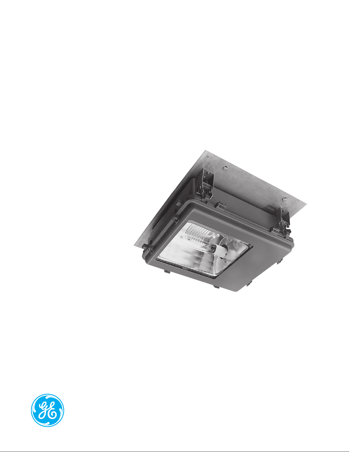
Tunnel Guard™ (TUN)
imagination at work
Page 2

Product Features
GE Tunnel Lighting luminaires are designed to meet varying light level requirements for tunnel entrances and interiors.
The combination of specialized photometric distributions offering easy eye adaptation, low glare and good visibility
make these fixtures a perfect choice for tunnel installations.
Applications
• For tunnels and underpasses
Housing
• Heavy-duty die-cast aluminum housing
Finish
• Dark gray powder paint finish
Rating
/
• Listed Suitable for Wet Locations
• Available with option for UL1598A “Suitable for
Outdoor, Salt Water Marine Locations” Contact factory
Mounting
• Flat surface for semi- recessed ceiling mounting
• Unistrut mounting adapter kit available – contact
factory
Unique Features
• Low-glare, specialized photometrics
• No-tool fixture removal for quick maintenance
(surface mounted only)
• Stainless steel external hardware
• Door assembly hinged and latched for no-tool
installation and removal
• Terminal Board is standard
• Tempered glass lens
• No-tool lamp replacement
• Plug-in no-tool replaceable ignitor
• Standard unit comes with 4 feet of #12-3 cable
out the top of the unit
• Luminaire normally shipped with hinges and latches
• CEILING MOUNTING PLATE (CMPxxx) IS REQUIRED
AND MUST BE ORDERED SEPARATELY.
(SEE MOUNTING ACCESSORY SELECTION TABLE)
Reflectors
• ALGLAS™ finish on aluminum faceted reflector
Page 3

Ordering Number Logic
Tunnel Guard™ (TUN)
T U N 4 C G F
_ _ _ - _ _ - _ - _ - _ - _ - _ _ _ - _ _ - _ _ - _
PROD. ID
Tunnel Guard
Luminaire
WATTAGE
07 = 70
10 = 100
15 = 150
(55V)
20 = 200
25 = 250
40 = 400
LIGHT
SOURCE
E = Energy Act
Compliant Pulse
MH (EPMH)
S = HPS
Standard: Lamp
not included.
VOLTAGE
60Hz
1 = 120
2 = 208
3 = 240
4 = 277
5 = 480
D = 347
BALLAST TYPE
SELECTION
See Ballast and
Photometric
Selection Table
A = Autoreg
G = Mag-Reg with
Grounded
Socket Shell
H = HPF Reactor
or Lag
K = Hot Restart
M = Mag-Reg
N = NPF Reactor
or Lag
P = CWI with
Grounded
Socket Shell
Ballast Selection Table
Light 120/208/240 347
Wattage Source 277/480 120X347
70, 100, 150 (55V) HPS G, H, K, M,N G,H,M*,N
200, 310 HPS A, M N/A
200, 310 HPS A, M N/A
250, 400 HPS A, G, K**, M A, G, M
250, 400 HPS A, G, K**, M A, G, M
250 EPMH A N/A
400 EPMH A N/A
NOTE: N/A = Not available *Not available in 120X347V **400W watt only
Ballast Type/Voltage
60Hz
AMBIENT
°C
4 = 40TUN =
IES DISTRIBUTION
TYPE
See Ballast and
Photometric Selection Table
CBM = Counter-Beam
HTV = Horizontal Type V
SYM = Symmetrical
(Medium Base
Lamp)
STM = Symmetrical
(Mogul Base Lamp)
MC3 = Medium, Cutoff,
Type III
MC4 = Medium, Cutoff,
Type IV
BEAM
ROTATION
NOTE = XX
Determined by
the orientation
of luminaire on
tunnel ceiling.
Tunnel drawings
of mounting
configurations
required.
COLOR
CG = Charcoal Gray
OPTIONS
F = Fusing
(Not Available
with Multivolt)
Photometric Selection Table
Light Socket Photometric Photometric
Wattage Source Base Size Distribution Curve Number
70, 100, 150 (55V) HPS Mogul STM 35-177701
70, 100, 150 (55V) HPS Mogul MC4 35-178045
70, 100, 150 (55V) HPS Mogul CBM 35-179111
200, 310 HPS Mogul CBM 35-177734
200, 310 HPS Mogul MC3 35-178044
250, 400 HPS Mogul CBM 35-177734
250, 400 HPS Mogul MC3 35-178044
400 EPMH* Mogul CBM 35-178581
400 EPMH* Mogul MC3** 35-179162
NOTE: All light sources are clear unless otherwise indicated.
*Lamp for 400 watt EPMH fixture must be E-18 or ED-28 only.
**Not Available with 0° Beam Rotation.
Page 4

Product Dimensions
CMP001 - Ceiling Mounting Plate
(Top Cable Entrance)
24.000 in. (610 mm)
8.000 in.
8.235 in.
(203 mm)
(209 mm)
16.000 in.
(406 mm)
.500 X 1.000 in. (6 Slots)
(13 X 25 mm)
20.000 in.
(508 mm)
27.000 in.
(686 mm)
Semi-Recessed Mounting
(No UL)
8.000 in.
(203 mm)
30.500 in. (775 mm)
28.000 in. (711 mm)
14.000 in.
(356 mm)
3.000 in.
(76 mm)
30.000 in.
(762 mm)
CMP002 - Ceiling Mounting Plate
(Side Cable Entrance on Latch Side of Housing)
24.000 in.
(610 mm)
8.000 in.
(203 mm)
8.235 in.
(209 mm)
14.000 in.
(356 mm)
.500 X 1.000 in. (6 Slots)
(13 X 25 mm)
20.000 in.
(508 mm)
27.000 in.
(686 mm)
30.000 in.
(762 mm)
Mounting Accessory Selection Table
ONE REQUIRED PER LUMINAIRE
CMP001 = Ceiling Mounting Plate (with six bolts)
CMP002 = Ceiling Mounting Plate (with four bolts)
26.500 in.
(673mm)
24.000 in.
(610 mm)
.500 X 1.000 in. (8 Slots)
(13 X 25 mm)
14.000 in.
(356 mm)
• Approximate Net Weight: 60 lbs (27 kgs)
• Suggested Mounting Height: 16 ft. (5 M)
DATA
GE Lighting Solutions • 1-888-MY-GE-LED • www.gelightingsolutions.com
1 - 8 8 8 - 6 9 - 4 3 - 5 3 3
GE Lighting Solutions, LLC is a subsidiary of the General Electric Company. The GE brand and logo are trademarks of the General Electric Company.
© 2012 GE Lighting Solutions, LLC. Information provided is subject to change without notice. All values are design or typical values when measured under laboratory conditions.
OLP-2923 (Rev. 06/13/12)
 Loading...