

GE Tumble action washer, Coin-Operated Commercial Tumble Action Washer Installation Instructions And Use & Care Manual
Coin- Operated Commercial
Tumble Action Washer
Installation Instructions and
Use and Care Guide
Machine À Laver Par Culbutage Commerciale
à encaissement automatique
Instructions d’installation et
Guide d’utilisation et d’entretien
P/N 134996400B (0711) www.GEAppliances.com
TABLE OF CONTENTS
Important Safety Instructions..........................................3
Pre-Installation Requirements.......................................4
Electrical Requirements.................................................4
Grounding Requirements..............................................4
Water Supply Requirements..........................................4
Drain Requirements........................................................4
Location Of Your Washer...............................................4
Rough-In Dimensions....................................................5
Unpacking.......................................................................6
Installation..................................................................6-7
Coin slide installation................................................7-9
Meter case instructions.................................................9
Replacement Parts..........................................................10
Parts lists....................................................................10-12
Consumer Support................................................13-14
Français..................................................................15-27
Before beginning installation, carefully read
these instructions. This will simplify the
installation and ensure the washer is
installed correctly and safely. Leave these
instructions near the washer after
installation for future reference.
NOTE: The electrical service to the washer
must conform with local codes and
ordinances and the latest edition of the
National Electrical Code, ANSI/NFPA 70.
NOTE: The instructions appearing in this
INSTALLATION AND SAFETY INSTRUCTIONS
manual are not meant to cover every possible
condition and situation that may occur. Common
sense and caution must be practiced when
installing, operating and maintaining any
appliance.
For GE warranty information or to contact a GE Service Center,
call 1-800-GE CARES or www.GEAppliances.com. In Canada
call 1-800-561-3344 or www.geappliances.ca.
If you need SERVICE or PARTS for your GE coin-operated
washer: be ready to give the model number, serial number and
date of purchase. Record below.
Model number________________________________________
Serial number_________________________________________
Purchase date_________________________________________
Record Coin Box
Key Number__________________________________________
Key number is on key and/or coin box.
Product Record
WASHER SAFETY
Your safety and the safety of others is very important. We have provided many important safety messages in the Installation
Instructions/Use & Care Guide and on your appliance. Always read and obey all safety messages.
This is the safety alert symbol. This symbol alerts you to hazards that can kill or hurt you or others. All safety messages will be
preceded by the safety alert symbol and the word "DANGER" or "WARNING". These words mean:
DANGER
All safety messages will identify the hazard, tell you how to reduce the chance of injury, and tell you what can happen if the
instructions are not followed.
property damage, personal injury or loss of life.
- Do not store or use gasoline or other flammable vapors and liquid in the vicinity of this or any other appliance.
- WHAT TO DO IF YOU SMELL GAS
· Do not try to light any appliance.
· Do not touch any electrical switch; do not use any phone in your building.
· Clear the room, building or area of all occupants.
· Immediately call your gas supplier from a neighbor’s phone. Follow the gas suppliers instructions.
· If you cannot reach your gas supplier, call the fire department.
Installation and service must be performed by a qualified installer, service agency or the gas supplier.
Your washer is equipped with a door safety interlock. Verify proper operation of interlock system daily, using the following procedure:
1. With the washer door open, insert the required number of coins and press the START button. THE WASHER MUST NOT START!
2. Close the washer door. Press the START button again to start the machine. Attempt to open the door, without exerting excessive
force. THE DOOR MUST NOT OPEN!
IF THE WASHER STARTS WITH THE DOOR OPEN, OR THE DOOR CAN BE OPENED WHILE THE WASHER IS OPERATING, THE
MACHINE MUST IMMEDIATELY BE TAKEN OUT OF SERVICE. DISCONNECT THE POWER CORD, AND MARK THE MACHINE "OUT
OF ORDER", UNTIL THE INTERLOCK SYSTEM IS REPAIRED, AND OPERATES AS DESCRIBED ABOVE.
You can be killed or seriously injured if you don't immediately follow instructions.
can be killed or seriously injured if you don't follow instructions.
You
For your safety the information in this manual must be followed to minimize the risk of fire or explosion or to prevent
2
Grounding type
w
grounding plug
hazard or electrical shock.
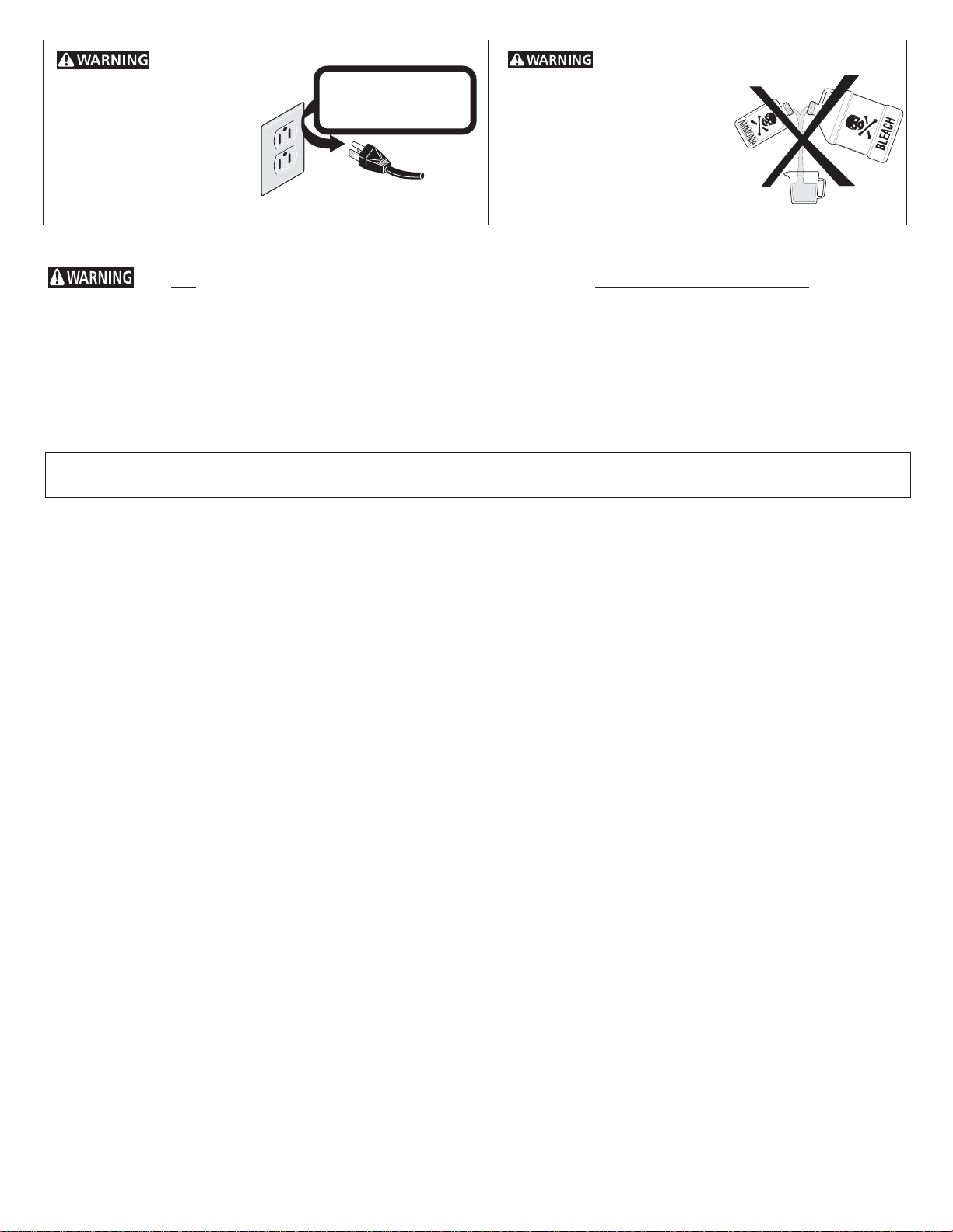
Avoid fire
Do not use an adaptor plug
or extension cord or
remove grounding prong
from electrical power cord.
Failure to follow this
warning can cause serious
injury, fire or death.
Grounding type wall receptacle
all receptacle
Do not under
Do not under any
any circumstances
circumstances cut, remove,
cut, remove,
or bypass
or bypass the grounding
the grounding prong
prong from this plug.
from this plug.
Power supply
Power supply cord with
cord with 3-prong
3-prong grounding plug
CORRECT Use this way ONLY
liquid chlorine bleach with
Do not use or mix
other household chemicals
such as toilet cleaners, rust
removers, acid or products
containing ammonia. These
mixtures can produce
dangerous fumes which can
cause serious injury or death.
Important Safety Instructions
Read all instructions before using this washer.
You can be killed or seriously injured if you don't follow these Important Safety Instructions:
• To reduce the risk of fire, electrical shock, or injury to persons when using this washer, comply with the basic warnings listed below.
• Failure to comply with these warnings could result in serious personal injuries.
Prevent Fire
• Do not wash items that have been previously cleaned in, soaked in, or spotted with gasoline, cleaning solvents, kerosene, cooking
oils, waxes, etc. Do not store these items on or near the washer. These substances give off vapors or chemical reactions that could
ignite or explode.
• Do not put oily or greasy rags or clothing on top of the washer. These substances give off vapors that could ignite the materials.
• Do not add gasoline, cleaning solvents, or other flammable or explosive substances to the wash water. These substances give
off vapors that could ignite or explode.
FOR YOUR SAFETY Do not store or use gasoline or other flammable vapors or liquids in the vicinity of this or
any other appliance.
• Under certain conditions, hydrogen gas may be produced in a hot water system that has not been used for 2 weeks or more.
HYDROGEN GAS IS EXPLOSIVE. If the hot water system has not been used for such a period, before using the washer, turn
on all hot water faucets and let the water flow from each for several minutes. This will release any accumulated hydrogen gas.
Hydrogen gas is flammable; do not smoke or use an open flame during this time.
• Failure to comply with these warnings could result in fire, explosion, serious bodily injury and/or damage to the rubber or plastic
parts of the washer.
Protect Children
• Do not allow children to play on or in the washer. Close supervision of children is necessary when the washer is used near children.
As children grow, teach them the proper, safe use of all appliances.
• Destroy the carton, plastic bag and other packing materials after the washer is unpacked. Children might use them for play. Cartons
covered with rugs, bedspreads or plastic sheets can become airtight chambers.
• Keep laundry products out of children's reach. To prevent personal injury, observe all warnings on product labels.
• Before the washer is removed from service or discarded, remove the washer lid to prevent accidental entrapment.
• Failure to comply with these warnings could result in serious personal injuries.
Prevent Injury
• Test door interlock system daily. Follow instructions on previous page.
• To prevent shock hazard and assure stability during operation, the washer must be installed and electrically grounded by a qualified
service person in accordance with local codes. Refer to INSTALLATION AND SAFETY INSTRUCTIONS for detailed grounding
procedures. If the washer is moved to a new location, have it checked and reinstalled by a qualified service person.
• To prevent personal injury or damage to the washer, the electrical power cord of the washer must be plugged into a properly
grounded and polarized 3-prong outlet. The third grounding prong must never be removed. Never ground the washer to
a gas pipe. Do not use an extension cord or an adaptor plug.
• Follow package directions when using laundry products. Incorrect usage can produce poisonous gas--resulting in serious injury
or death.
- Do not combine laundry products for use in 1 load unless specified on the label.
- Do not mix chlorine bleach with ammonia or acids such as vinegar.
• To prevent serious personal injury and damage to the washer:
- All repairs and servicing must be performed by an authorized servicer unless specifically recommended in this
INSTALLATION AND SAFETY INSTRUCTIONS manual. Use only authorized factory parts.
- Do not tamper with controls.
- Do not install or store the washer where it will be exposed to the weather.
• To reduce the risk of electric shock, disconnect this appliance from the power supply before attempting any user maintenance.
Turning the controls to the OFF position does not disconnect this appliance from the power supply.
• To prevent injury, do not reach into the washer while parts are moving. Before loading, unloading or adding items, push in the cycle
selector knob and allow the tub to coast to a complete stop before reaching inside.
• Failure to comply with these warnings could result in serious personal injuries.
• This washer is equipped with an electrical overload protector. The motor will stop if it becomes overheated. The washer will
automatically restart after a cool down period of up to 30 minutes, if the washer has not been manually turned off during this time.
SAVE THESE INSTRUCTIONS
3
3
PRE-INSTALLATION REQUIREMENTS
DRAIN REQUIREMENTS
Tools Required for Installation:
1. 1/4 in. nut driver
2. 3/8 in. socket with ratchet.
3. 3/8 in. open end wrench.
4. 7/16 in. socket with ratchet.
5. 9/16 in. open end wrench.
6. Channel-lock adjustable pliers.
7. Carpenter’s level.
ELECTRICAL REQUIREMENTS
CIRCUIT - Individual, properly polarized and grounded 15 amp.
branch circuit fused with 15 amp. time delay fuse or circuit breaker.
POWER SUPPLY - 2 wire, with ground, 120 volt, single phase, 60
Hz, Alternating Current. NOTE: The use of this washer with power
created by gas powered generators, solar powered generators,
wind powered generators or and other generator other than the
local utility company is not recommended.
OUTLET RECEPTACLE - Properly grounded 3-prong receptacle to
be located so the power supply cord is accessible when the washer
is in an installed position. NOTE: GFI (Ground Fault Interrupter)
receptacle is not required.
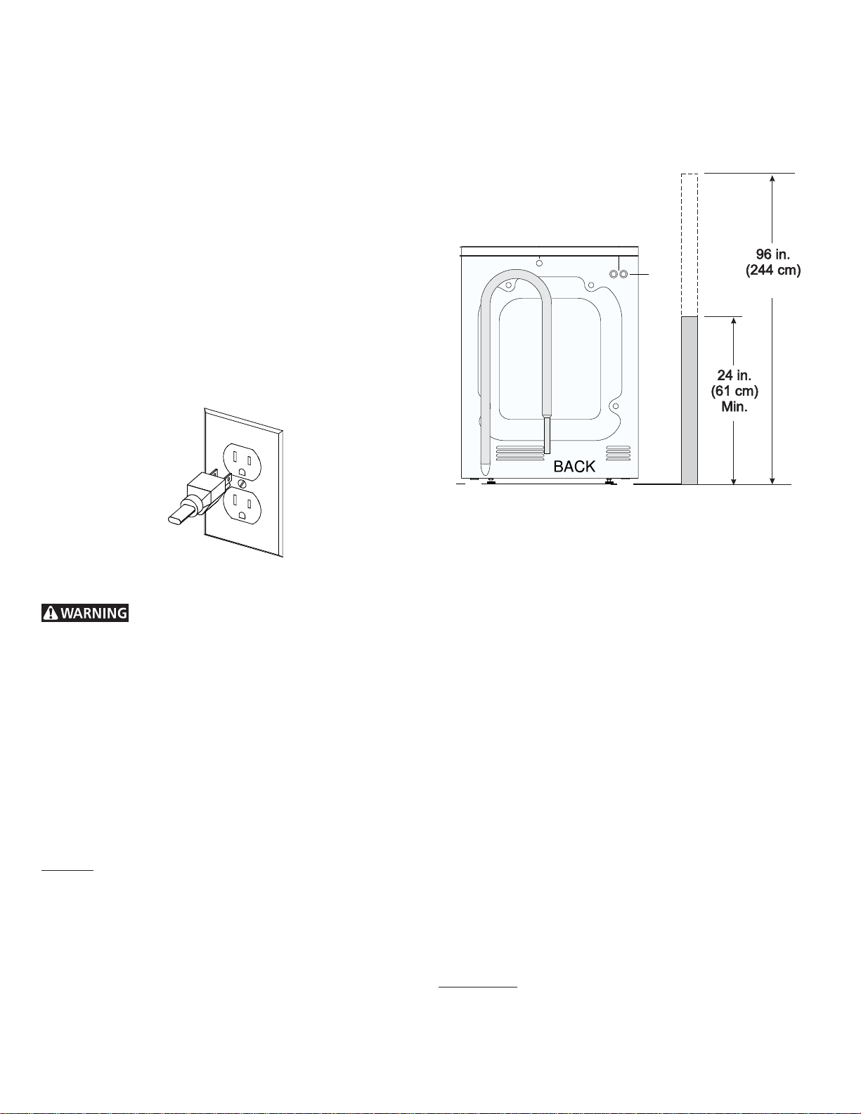
Models equipped with drain pump:
1. Drain MUST be capable of eliminating 17 gals (64.3 L) per
minute.
2. A standpipe diameter of 1-1/4 in. (3.18 cm) minimum.
3. The standpipe height above the floor should be:
Max.Max.
Max.
Max.Max.
GROUNDING REQUIREMENTS
Improper connection of the equipment grounding
conductor can result in a risk of electrical shock. Check with a
licensed electrician if you are in doubt as to whether the appliance
is properly grounded.
1. The washer MUST be grounded. In the event of malfunction
or breakdown, grounding will reduce the risk of electrical
shock by a path of least resistance for electrical current.
2. Since your washer is equipped with a power supply cord
having an equipment-grounding conductor and a grounding
plug, the plug MUST be plugged into an appropriate, copper
wired receptacle that is properly installed and grounded in
accordance with all local codes and ordinances or in the
absence of local codes, with the National Electrical Codes,
ANSI/NFPA 70 (latest edition). If in doubt, call a licensed
electrician.
DO NOT cut off or alter the grounding prong on the power supply
cord. In situations where a two-slot receptacle is present, it is the
owner’s responsibility to have a licensed electrician replace it
with a properly grounded three prong grounding type
receptacle.
WATER SUPPLY REQUIREMENTS
Hot and cold water faucets MUST be installed within 42 inches
(107 cm) of your washer’s water inlet. The faucets MUST be 3/4
inch (1.9 cm) garden hose type so inlet hoses can be connected.
Water pressure MUST be between 10 and 120 pounds per square
inch (maximum unbalance pressure, hot vs. cold, 10 psi.) Your
water department can advise you of your water pressure.
NOTE:
Drain hose attached to the washer can reach a 58 in. (147 cm)
high standpipe. For higher standpipe use hose P/N 134592701,
available from an authorized parts distributor. If drain is less
than 24 in. (61 cm), install a siphon break kit, available at your
local hardware store.
Models equipped with gravity drain:
1. Floor drain MUST be capable of eliminating 17 gals (64.3 L)
per minute.
2. Floor drain diameter must be at least 1/2 inch larger than
drain hose.
LOCATION OF YOUR WASHER
See rough-in dimensions on the next page (Figure 1).
DO NOT INSTALL YOUR WASHER:
1. In an area exposed to dripping water or outside weather
conditions. The ambient temperature should never be below
60 degrees F (15.6 degrees C) for proper washer operation.
2. In an area where it will come in contact with curtains or
drapes.
3. In an area (garage or garage-type building) where gasoline
of other flammables are kept or stored (including
automobiles).
4. On carpet. Floor MUST be solid with a maximum slope of
1/2 in. per foot (1.27 cm per 30.5 cm). To ensure vibration or
movement does not occur, reinforcement of the floor may
be necessary.
IMPORTANT MINIMUM INSTALLATION CLEARANCES
When installed in alcove: Sides, Rear, Top = 0 in (0 cm).
When installed in closet: Sides, Rear, Top = 0 in (0 cm),
Front = 1 in (2.54 cm).
Closet door ventilation openings required: 2 louvers each 60 in
(387 cm²) - 3 in (7.6 cm) from top and bottom of door.
4
4
²
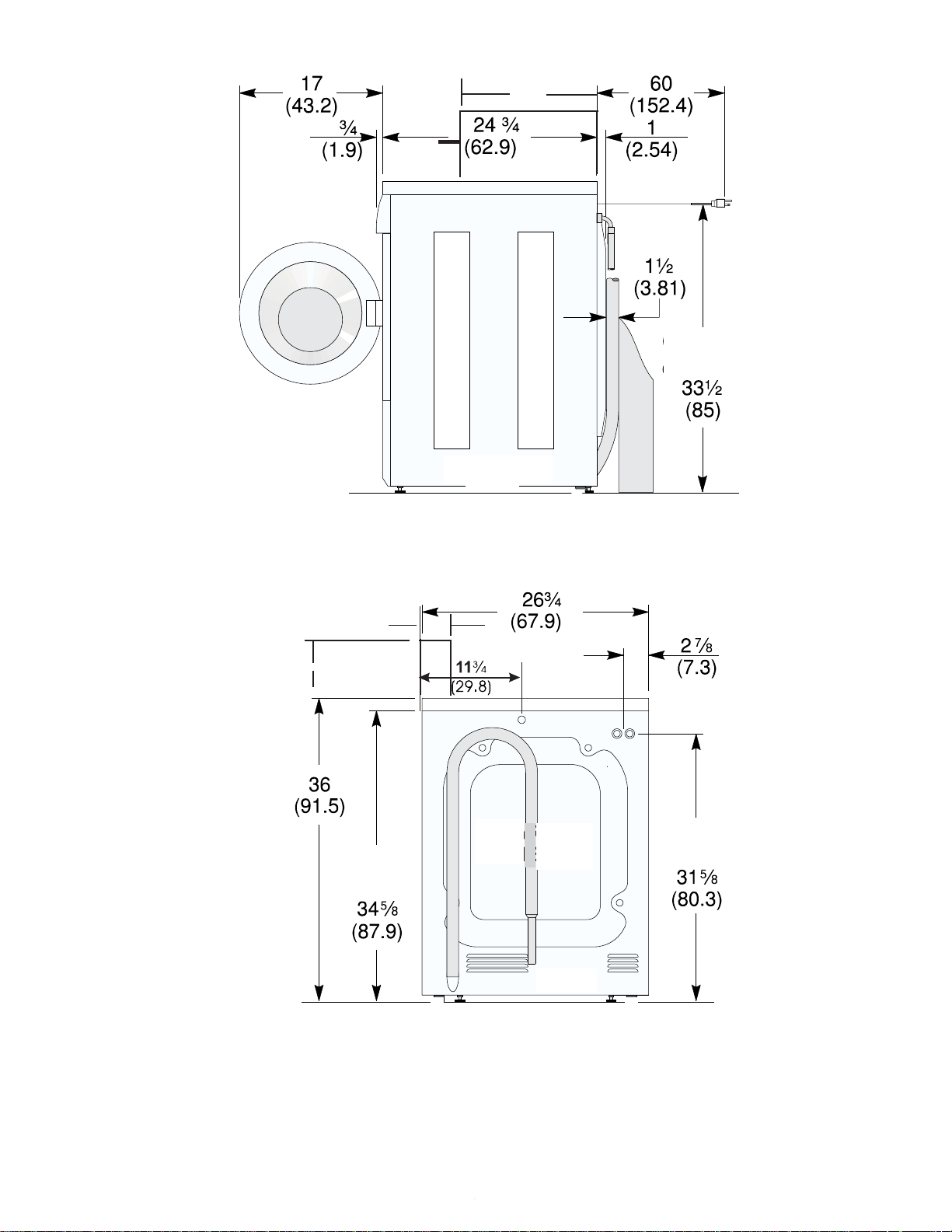
ROUGH-IN DIMENSIONS
17
<
(43.2)
>
SIDE
POWER
CORD
inch (cm)
^
(20.4)
v
UNDER
COUNTER
43/8
(11.2)
8
<>
WATER
INLETS
Ñ
Ò
inch (cm)
BACK
(Figure 1).
5
5
UNPACKING
1. Cut the shipping carton along the dotted line along the base
of the unit.
2. While in the carton carefully lay the washer on its back
side.
3. Removethe styrofoam base.
4. Carefully return the washer to an upright position and remove
the carton.
5. Carefully move the washer to within 4 feet (122cm) of the
final location.
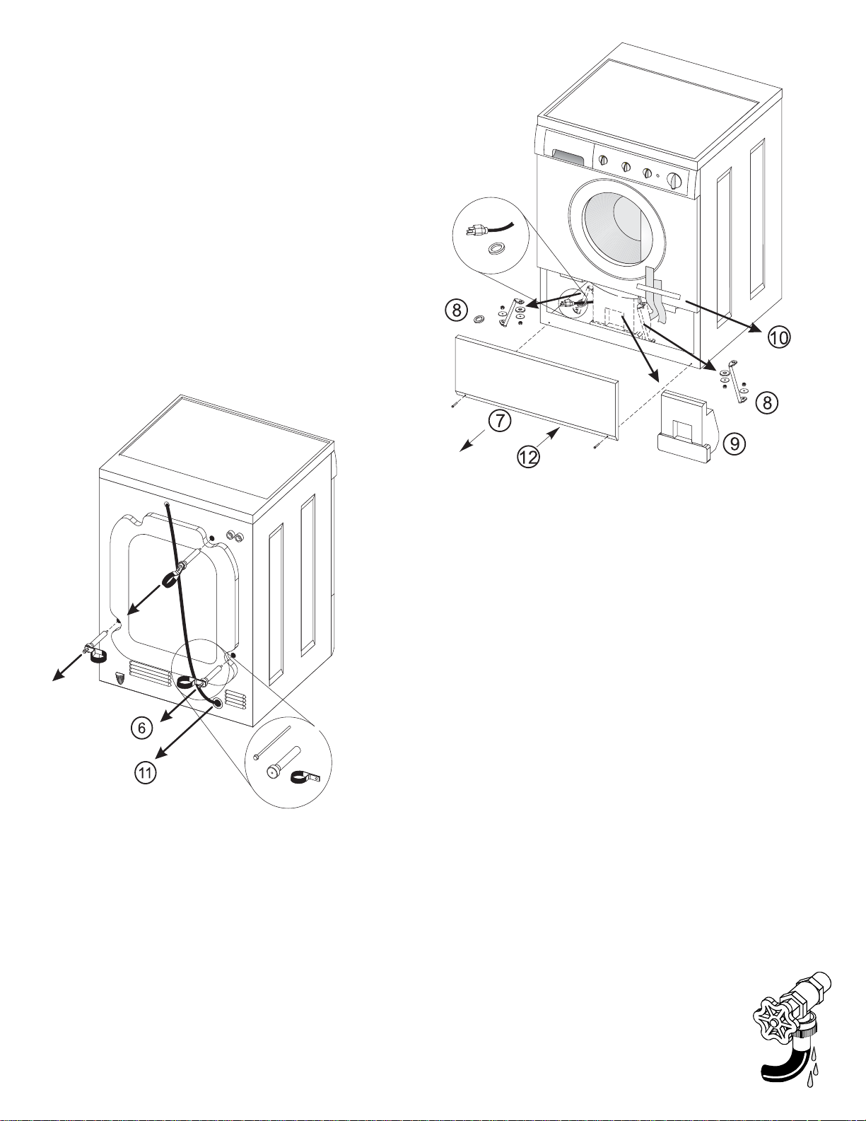
6. Remove the following from the back side of the washer:
3 bolts,
3 yellow plastic spacers,
2 or 3 metal "P" clamps.
BOLT
SPACER
"P" CLAMP
7. Remove the service panel from the front of the washer.
8. Remove the 4 nuts and 6 large washers that attach the 2
yellow shipping braces to the drum and the base. Lift up on
the drum and remove the braces (a yellow ribbon surrounds
the items to be removed). These braces must be removed to
allow the power supply cord to be released from the shipping
ring.
9. Remove the large styrofoam block located under the drum.
Lift up on the drum, tilt the base of the foam block inwards
toward the rear of the washer until free, then pull it out.
10. Remove and discard the yellow ribbon and label from the
front of the washer.
11. From the rear of the washer, carefully pull out the power
supply cord through the hole in the backsheet.
12. Replace the service panel and screws.
NOTE: If the washer is to be transported at a later date, the
shipping support hardware must be reinstalled to prevent
shipping damage.
INSTALLATION
1. Run some water from the hot and cold faucets to flush the
water lines and remove particles that might clog up the water
valve screens.
2. Remove the inlet hoses and rubber washers from the plastic
bag and install the rubber washers in each end of the inlet
hoses.
3. Carefully connect the inlet hose marked "HOT" to the outside
"H" outlet of the water valve. Tighten by hand, then tighten
another 2/3 turn with pliers. Carefully connect the other
inlet hose to the inside "C" outlet of the water valve. Tighten
by hand, then tighten another 2/3 turn with pliers. Do not
crossthread or over-tighten these connections.
4. Connect the inlet hose ends to the HOT and
COLD water faucets tightly by hand, then
tighten another 2/3 turn with pliers. Turn the
water on and check for leaks.
6
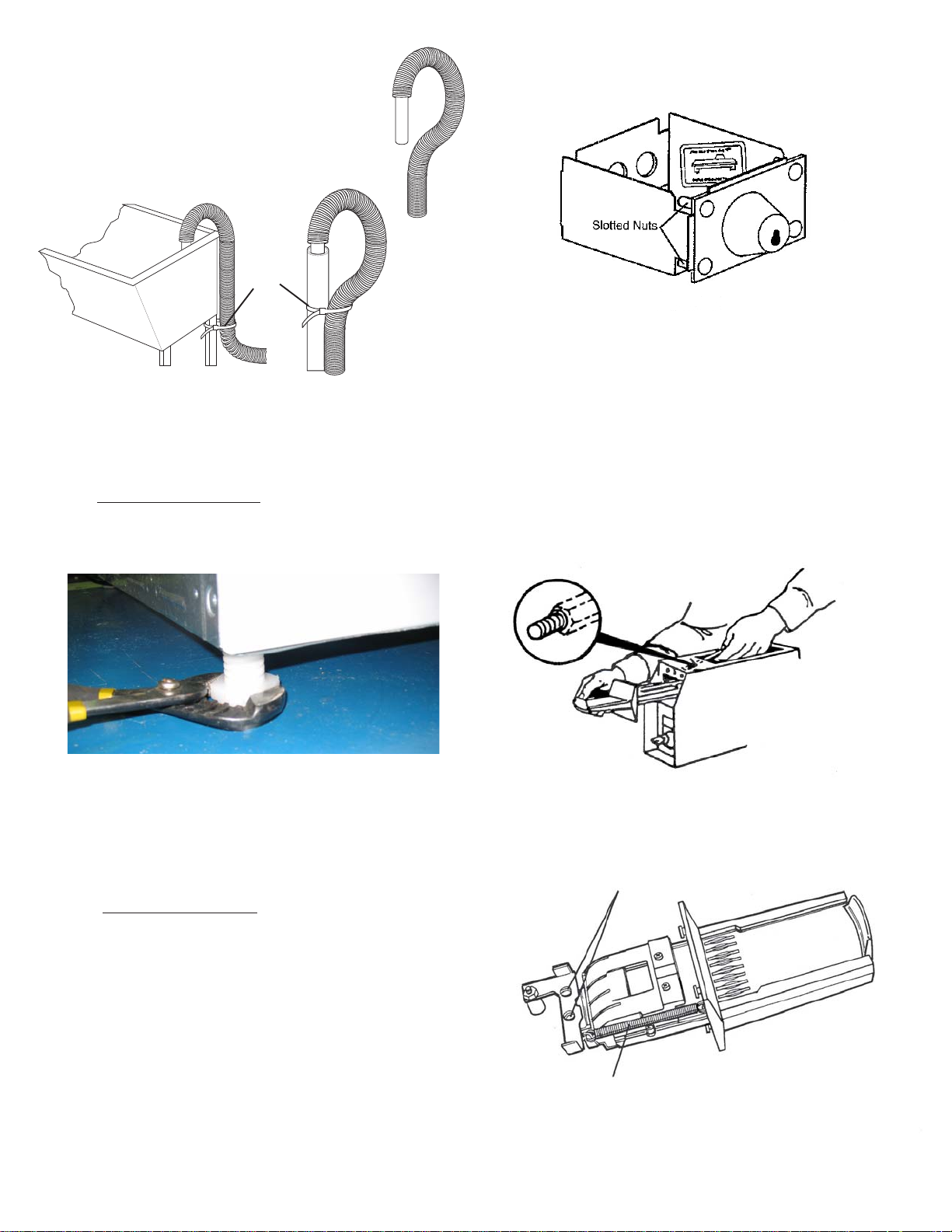
5. On machines equipped with drain pump, form
a U shape on the end of the drain hose, with
the hose pointed toward the drain.
NOTE: If the drain hose is placed in a standpipe
without forming a U shape, a siphoning action
could occur. There must be an air gap around
the drain hose. A snug hose fit can also cause a
siphoning action.
Cable
Tie
6. Carefully move the washer to its final location.
NOTE: Do not use the dispenser drawer or door to lift washer.
Excessive noise and vibration can be prevented by properly
leveling the washer.
7. For
free standing installation and with the washer in it’s final
position, place a level on top of the washer. Adjust the
leveling legs so the washer is level front-to-rear and side-toside, and stable corner-to-corner.
COIN BOX ADJUSTMENT
The tight fit of the money box is set at the factory. Customer may
loosen fit as desired by loosening the slotted nuts. See FIG.2.
FIGURE 2
Keep A record of all coin-box key numbers.
A lost key can only be replaced by ordering the key numbers from
the place were the unit was purchased. The key number is located
both on the key and behind the end panel of the coin box. If the
key number is not available, the lock must be drilled out to remove
the coin box.
Instructions for Changing Vend Price
TOOLS NEEDED
• Medium sized slotted screwdriver
• Small slotted Phillips screwdriver
Place all screws and other items removed from coin slide assembly
on a cloth so they will not get lost.
STEP 1
Remove slide mechanism from meter case. (see FUGURE 1).
Press down on alternate corners and sides and feel for the
slightest movement. Adjust the appropriate leg so the
washer is SOLID on the floor on ALL four legs. Keep the
leveling leg extension at a minimum for best performance of
thewasher.
8. For pedestal installations, See additional installation
instructions included with the pedestal.
9. Plug the power cord into a grounded outlet.
NOTE: Check to ensure the power is off at the circuit breaker/
fuse box before plugging the power cord into an outlet.
10. Turn on the power at the circuit breaker/fuse box.
11. Be sure you have read the "Important Safety Instructions"
before operating this washer.
12. Run the washer through a complete cycle. Check for water
leaks and proper operation.
13. Keep these instructions for future reference.
NOTE: A wiring diagram is located inside the washer on the
side panel.
FIGURE 1
STEP 2
Remove the coin slide extension from coin slide by removing two
mounting screws and spacers
(see FIGURE 2).
(2) Mounting Screws
and Spacers
FIGURE 2
Slide Return Spring
7
7
STEP 3
Remove coin slide from coin chute:
• Unhook and remove the coin slide return spring. (see FIGURE 2).
• Turn coin slide mechanism upside down.
• Remove coin slide stop by taking out two screws to the chute bottom
(see FIGURE 3).
(2) Slide Stop
Screws
FIGURE 3
• Pull coin slide out of coin chute (see FIGURE 4).
FIGURE 4
STEP 4
Turn coin slide upside down and remove screw that holds coin receiver
block (see FIGURE 5).
(1) Receiver Block Screw
FIGURE 5
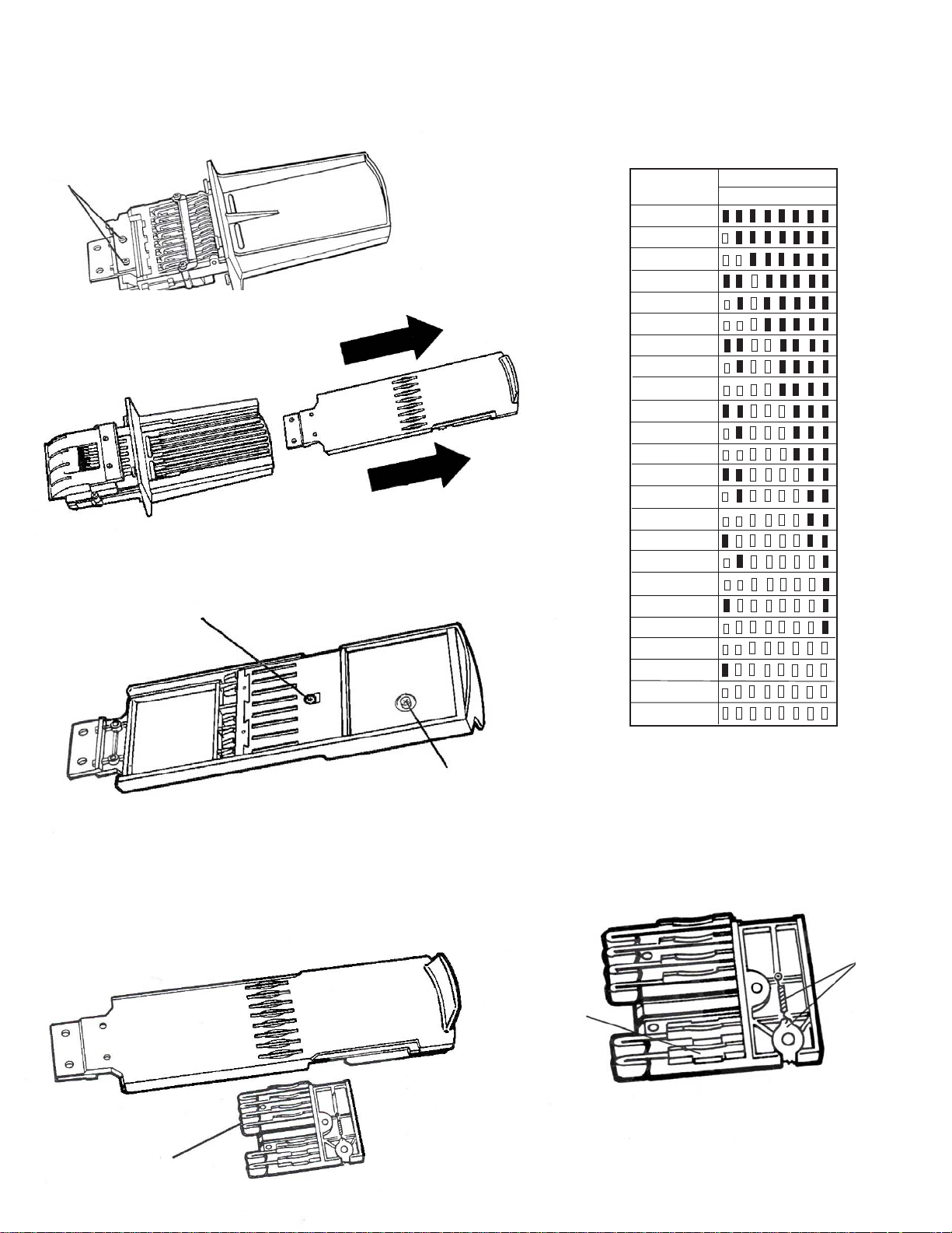
STEP 6
Set new vend price by adding or removing the appropriate
block-out keys and/or dime inserts according to th Table
of Vend Prices
(see FIGURE 7).
FIGURE 7
TABLE OF VEND PRICE
NOTE:
Black
colored
slots are
closed off
by blockout key.
VEND
PRICE
0
$.10
$.20
$.25
$.35
$.45
$.50
$.60
$.70
$.75
$.85
$.95
$1.00
$1.10
$1.20
$1.25
$1.35
$1.45
$1.50
$1.60
$1.70
$1.75
$1.85
$2.00
COIN SLOTS
1 2 3 4 5 6 7 8
Spare Parts
Compartment
STEP 5
and Screw
Remove coin receiver block from coin slide (see FIGURE 6):
• Turn coin slide right side up. Keep coin receiver block in place with
your fingers.
• Carefully lift coin slide from coin receiver block. If necessary, shake
coin slide gently to loosen block.
FIGURE 6
Coin Receiver
Block
8
8
To remove block-out keys, pull straight up.
NOTE: Be sure block-out keys and /or dime inserts are
seated properly and ratchet dog is in place with irs spring
connected (see FIGURE 8).
Be sure the proper coin sizing block is in place.
Ratchet
Dog and
Spring
Block-Out
Keys
FIGURE 8
Change coin sizing block:
• Remove two screws that hold upper coin chute cover.
Remove cover (see FIGURE 9).
FIGURE 9
(2) Upper Coin
Chute Cover
Screws
Anti-Cheat
Gate
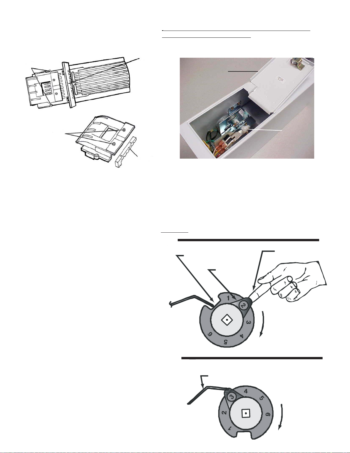
Meter Case Instructions
INSTRUCTIONS TO CHANGE THE NUMBER OF COIN SLIDE
INSERTIONS TO START APPLIANCE.
1. Disconnect power from machine.
2. Remove meter-case service door. (Fig.1)
Remove
meter-case
service door
(2) Coin Sizing
Block Screws
Coin Sizing
FIGURE 10
Block
• Remove two screws that hold coin sizing block to upper
coin chute cover cover (see FIGURE 10).
• Put new coin sizing block in place. Reinsert and tighten
mounting screws.
• Replace coin chute cover. Reinsert and tighten screws.
STEP 7
Replace coin receiver block into slide:
• Hold coin receiver right side up in the palm of one hand.
• Lower coin slide until coin receiver block fits into the
coin slide cavity. CAUTION: Do not dislodge ratchet
dog and spring.
• Hold coin receiver block in place with your fingers and
turn slide upside down.
• Insert and tighten screw.
STEP 8
Install slide into coin chute. Slide can only be pushed in if
the anti-cheat gate in flange is pushed to the left. (see
FIGURE 9).
STEP 9
Replace coin slide stop with two screws. Replace coin
slide return spring. Replace coin slide extension with two
screws (be sure spacers are in place).
Shaft and
cam
assembly
FIGURE 1
3. Turn Shaft & Cam Assembly in a clockwise direction until switch
lever arm drops into cam notch (Fig. 2).
4. Lift Adjusting Tab away from cam with finger and turn Tab to desired
number. Make sure Tab\ locks into place in new position.
5. Turn Shaft & Cam Assembly in a clockwise direction until switch
lever arm is on top of Tab to assure that both mechanism switches
are open (Fig. 3).
6. Replace meter-case service door and reconnect power to machine.
EXAMPLE: To change from $1 to $2 move tab from 1 to 2.
FIGURE 2
CAM NOTCH
ADJUSTMENT
TA B
E
7
TO LIFT
USE FINGER
TO LIFT PAD
CLOCKWISE
DIRECTION
STEP 10
Replace coin slide mechanism in meter case. Replace and
tighten coin slide mounting bolt.
NOTE: It may be easier to insert coin slide mounting bolt if
you remove the timer from the mounting screws temporarily.
FIGURE 3
SWITCH LEVER ARM
7
9
9
FIGURE
 Loading...