

GE 40, TruVision DVR 40 User Manual

GE
Security
P/N TVR40 uman-EN • REV R1.0• ISS 02MAY10
TruVision DVR 40 User Manual

Copyright © 2010 GE Security, Inc.
This document may not be copied in whole or in part or otherwise reproduced without prior
written consent from GE Security, Inc., except where specifically permitted under US and
international copyright law.
Disclaimer
The information in this document is subject to change without notice. GE Security, Inc.
(“GE Security”) assumes no responsibility for inaccuracies or omissions and specifically disclaims
any liabilities, losses, or risks, personal or otherwise, incurred as a consequence, directly or
indirectly, of the use or application of any of the contents of this document. For the latest
documentation, contact your local supplier or visit us online at www.gesecurity.eu
This publication may contain examples of screen captures and reports used in daily operations.
Examples may include fictitious names of individuals and companies. Any similarity to names
and addresses of actual businesses or persons is entirely coincidental.
Trademarks and patents GE and the GE monogram are trademarks of General Electric Company.
Other trade names used in this document may be trademarks or registered trademarks of the
manufacturers or vendors of the respective products.
Intended use
Use this product only for the purpose it was designed for; refer to the data sheet and user
documentation for details. For the latest product information, contact your local supplier or visit
us online at www.gesecurity.eu
Certification and compliance
European Union directives
1999/5/EC (R&TTE directive): Hereby, GE Security declares that this device is in compliance with
the essential requirements and other relevant provisions of Directive 1999/5/EC.
2002/96/EC (WEEE directive): Products marked with this symbol cannot be disposed of as
unsorted municipal waste in the European Union. For proper recycling, return this product to
your local supplier upon the purchase of equivalent new equipment, or dispose of it at
designated collection points. For more information see: www.recyclethis.info
2004/108/EC (EMC directive): Non-European manufacturers must designate an authorized
representative in the Community. Our authorized manufacturing representative is:
GE Security B.V., Kelvinstraat 7,
6003 DH Weert, The Netherlands.
2006/66/EC (battery directive): This product contains a battery that cannot be disposed of as
unsorted municipal waste in the European Union. See the product documentation for specific
battery information. The battery is marked with this symbol, which may include lettering to
indicate cadmium (Cd), lead (Pb), or mercury (Hg). For proper recycling, return the battery to your
supplier or to a designated collection point. For more information see: www.recyclethis.info
Contact information For contact information see our Web site: www.gesecurity.eu
.

i
Content
1. Product overview ......................................................................................................................1
Product description ................................................................................................................................................................................ 1
Unpacking the TVR 40 and its accessories.................................................................................................................................. 1
Installation environment...................................................................................................................................................................... 2
2. TVR 40 installation....................................................................................................................3
Connecting the devices ........................................................................................................................................................................ 3
Connecting alarm inputs and outputs........................................................................................................................................... 4
Connecting the TVR 40 to a PC.......................................................................................................................................................... 4
Setting up a PTZ dome camera ........................................................................................................................................................ 5
Connect a TVR 40 to a PTZ dome camera ..................................................................................................................... 5
Configure the PTZ protocols for GE Security cameras............................................................................................. 5
Wiring the TVK-505U keypad............................................................................................................................................................. 7
Monitor connections .............................................................................................................................................................................. 8
3. Controlling the TVR 40 .............................................................................................................9
Using the front panel........................................................................................................................................................................... 10
Using the IR remote control..............................................................................................................................................................12
Using the mouse....................................................................................................................................................................................13
Using the Web browser......................................................................................................................................................................14
4. Basic operations..................................................................................................................... 16
Turning on the TVR 40 .........................................................................................................................................................................16
Logging in using PINs ..........................................................................................................................................................................17
Live mode..................................................................................................................................................................................................17
Selecting a monitor...............................................................................................................................................................................19
Viewing in multiscreen........................................................................................................................................................................19
Manual recording ..................................................................................................................................................................................20
Searching and playing back recorded video............................................................................................................................21
Control playback progress .................................................................................................................................................. 22
Search recorded video..........................................................................................................................................................23
Playback recorded video......................................................................................................................................................25
Archiving recorded files......................................................................................................................................................................26
Quick archive .............................................................................................................................................................................26
Manually select files to archive.........................................................................................................................................26
Automatically backup recorded files..............................................................................................................................28
Controlling a PTZ camera ..................................................................................................................................................................29
Manually acknowledging an alarm...............................................................................................................................................31
Overview of the menu structure.....................................................................................................................................................32
Navigating through a menu screen................................................................................................................................33
Turning off the TVR 40.........................................................................................................................................................................34
5. Display settings...................................................................................................................... 36
Selecting a language ...........................................................................................................................................................................37
Setting the device ID............................................................................................................................................................................ 38
Setting the PIN requirement.............................................................................................................................................................38

ii
Displaying the status bar...................................................................................................................................................................38
Menu timeout ..........................................................................................................................................................................................39
Selecting video standard ...................................................................................................................................................................39
Video scaling............................................................................................................................................................................................ 39
Menu transparency ..............................................................................................................................................................................40
Defining VGA resolution......................................................................................................................................................................40
Setting system time and date..........................................................................................................................................................40
Multiscreen and sequencing............................................................................................................................................................41
6. Camera settings..................................................................................................................... 44
Setting up the camera title................................................................................................................................................................45
Positioning the camera title..............................................................................................................................................................45
Modifying the image quality.............................................................................................................................................................46
Displaying the current time and date on-screen ...................................................................................................................47
Motion detection....................................................................................................................................................................................48
Privacy masks..........................................................................................................................................................................................52
Viewing a camera tamper alarm...................................................................................................................................................54
Setting up a video loss alarm...........................................................................................................................................................56
7. Recording settings................................................................................................................. 58
Configuring the recording settings ...............................................................................................................................................58
Responding to full HDD.......................................................................................................................................................................59
Using an external storage device for backup..........................................................................................................................60
Auto delete mode (ADM).....................................................................................................................................................................60
Modifying the recording parameters of a camera................................................................................................................60
Setting up a camera’s recording schedule................................................................................................................................63
8. Network settings.................................................................................................................... 66
Network settings....................................................................................................................................................................................67
E-mail settings ........................................................................................................................................................................................68
Advanced IP settings............................................................................................................................................................................69
PPPoE dial-up settings.........................................................................................................................................................................71
DDNS settings..........................................................................................................................................................................................72
9. Alarm settings ........................................................................................................................ 75
Alarm relay outputs..............................................................................................................................................................................75
External alarm input.............................................................................................................................................................................76
External alarm output .........................................................................................................................................................................78
Notification settings .............................................................................................................................................................................80
10. PTZ settings............................................................................................................................. 81
Description of preset, preset tour, and shadow tour options...........................................................................................82
PTZ settings ..............................................................................................................................................................................................82
Using preset positions.........................................................................................................................................................................83
Using shadow tours..............................................................................................................................................................................86
11. User settings ........................................................................................................................... 87
Overview of users and PINs..............................................................................................................................................................88
Modifying a user’s PIN.........................................................................................................................................................................89
Adding a new user ................................................................................................................................................................................89
Modifying operational rights............................................................................................................................................................90

iii
Setting up a MAC....................................................................................................................................................................................91
Deleting a user........................................................................................................................................................................................92
12. System settings...................................................................................................................... 93
Capturing text insertions....................................................................................................................................................................94
Handling transaction information.................................................................................................................................................96
Configuring the RS-232.......................................................................................................................................................................97
Upgrading the firmware.....................................................................................................................................................................98
Restoring factory default settings .................................................................................................................................................99
Managing the hard drive................................................................................................................................................................. 100
Viewing system logs.......................................................................................................................................................................... 101
Rebooting the TVR 40 .......................................................................................................................................................................102
Viewing system information.......................................................................................................................................................... 103
13. Troubleshooting and support............................................................................................ 105
Troubleshooting your system....................................................................................................................................................... 105
Contacting technical support ....................................................................................................................................................... 106
Appendix 1: Specifications ........................................................................................................... 107
Index................................................................................................................................................. 109
TVR 40 Menu Map........................................................................................................................... 112


TruVision DVR 40 User Manual 1
1. Product overview
Product description
The second generation of TVR 40 uses H.264, the latest video compression standard. This standard
offers 25 frames per channel per second at CIF resolution. This compression technology delivers
compact but excellent quality images.
The TruVision DVR 40 offers 4, 8 or 16 channels of analog recording, all up to 4CIF resolution (704 x
576). The dual streaming functionality allows the user to set up different settings for recording and
streaming video. TVR 40 supports both variable bit rate and variable frame rate. The dual streaming
functionality allows the user to set up different settings for recording and streaming video. TruVision
DVR 40 incorporates Triplex functionality for simultaneous transmitting, viewing live video, and
recording.
The TruVision DVR 40 series embedded digital video recorder is a digital surveillance product. It uses
an embedded microcontroller TVR 40 (MCU) and an embedded real-time operating system (RTOS),
combining the most advanced technology in the information industry, such as video and audio
encoding/decoding, hard disk recording, and TCP/IP. The firmware is burned into the flash, making it
more stable and reliable.
TruVision DVR 40 series has the features of both a digital video recorder (DVR) and a digital video
server (DVS). It can be used as a standalone device but also to build a powerful surveillance network,
such as widely used in the banking, telecommunications, manufacturing, and transportation sectors.
Unpacking the TruVision DVR 40 and its accessories
When you receive the product check the package and contents for damage, and that all the items
are included. There is an item list in the package. If any of the items are damaged or missing, please
contact your local supplier.
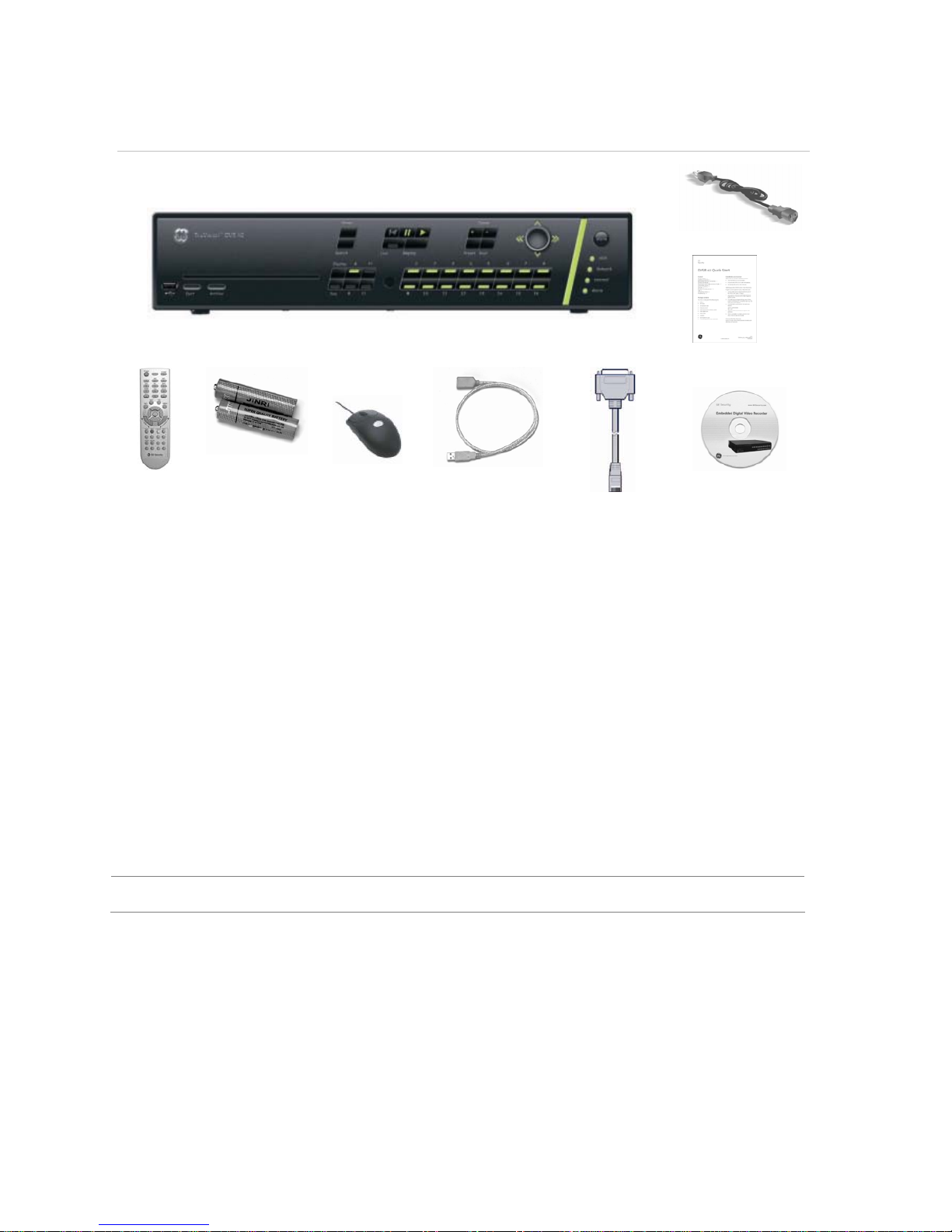
2 TruVision DVR 40 User Manual
Figure 1: Items shipped with product
AC mains cable
QuickStart Guide
IR remote
control
AAA batteries USB mouse USB extension cable RS-232 cable CD with
documentation &
utilities
Installation environment
Ventilation: Do not block any ventilation openings. Install in accordance with the manufacturer’s
instructions. Ensure that the location planned for the installation of the unit is well ventilated.
Regularly clean the unit by gently brushing it.
Temperature: Consider the TruVision DVR 40’s operating temperature (-10 to 50°C) and noncondensing humidity specifications (10 to 90%) before choosing an installation location. Extremes of
heat or cold beyond the specified operating temperature limits may cause the TruVision DVR 40 to
fail. Do not install the unit on top of other hot equipment. Leave space between rack mounted units.
Moisture: Do not use the unit near water. Moisture can damage the internal components. To reduce
the risk of fire or electric shock, do not expose this unit near to rain or moisture.
Chassis: Other equipment may be placed on top of the unit if it weighs less than 16 kg.
WARNING: Before installing the unit, please ensure that the power to the unit is switched off.
TruVision DVR 40 User Manual 3
2. TruVision DVR 40 installation
This section describes how to connect the TruVision DVR 40 unit.
Connecting the devices
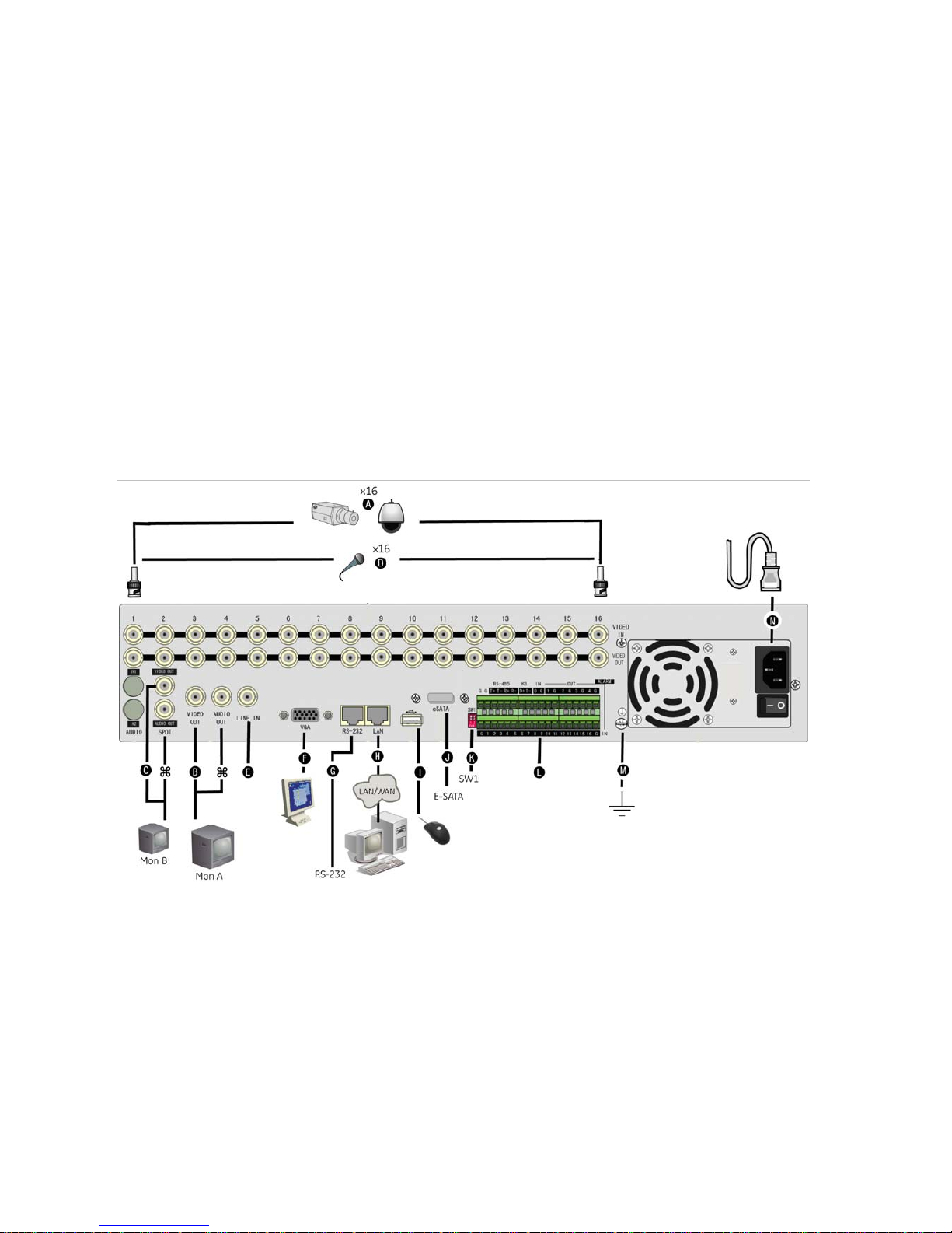
Figure 2 shows the back panel connections and describes each connector. There are variations
between the different model types.
Figure 2: TruVision DVR 40 back panel connections (16-channel model shown)
Required connections
A. Connect up to 16 cameras to the standard BNC video inputs.
Note: If a camera is incorrectly connected to the TVR 40, the monitor shows a Video Loss message. Check the
connection and reconnect the camera if necessary.
B. Connect monitor A (main) to the output VIDEO OUT. Connect the audio output () to AUDIO OUT if required. You can
use either analog or VGA output. Both outputs will display the same video information.
Optional connections
C. Connect a spot monitor (Mon B) to the TVR 40. Connect the monitor video to VIDEO OUT. Connect the monitor audio (if
used) to AUDIO OUT ().
D. Connect up to 16 audio signals to the standard BNC audio inputs (315 mV).
E. For future use.
F. Connect the VGA display (max. 1024 × 768 @ 60 Hz).
G. Connect an ATM or optional ProBridge using the supplied RS-232 cable.
4 TruVision DVR 40 User Manual
H. Connect the network devices.
I. Connect the USB mouse (supplied).
J. Connect the E-SATA for archive and storage expansion.
K. Terminate the line using this RS-485 switch. The default setting is OFF.
L. Connect the external data and alarm input/output (I/O) cable. See Figure 3 on page 4 for more information.
M.
Connect the TVR 40 to ground.
Power connection
N. Connect the power cord to the TVR 40. Be sure all devices are connected and turned on before you turn on the
TruVision DVR 40.
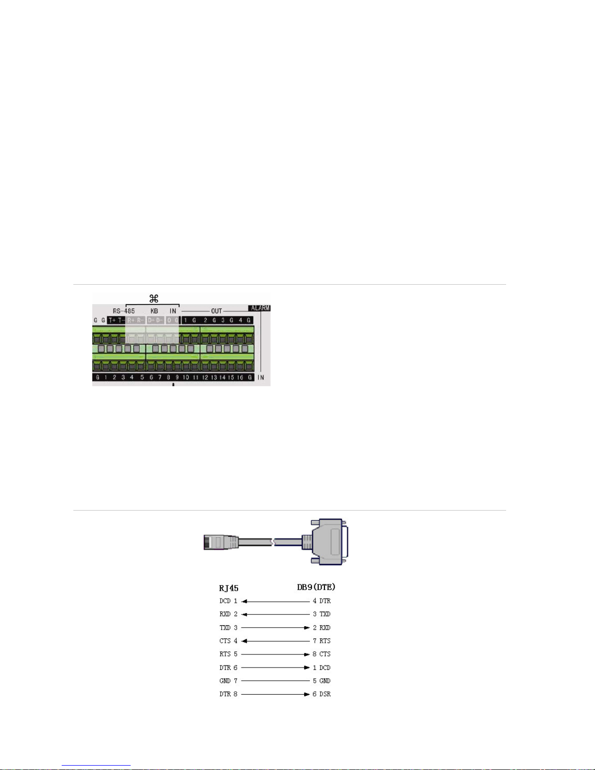
Connecting alarm inputs and outputs
Figure 3: Connecting the external data and alarm I/O cable
: Not used
RS-485 T+ T-: Connect PTZ camera data
Alarm output port:
1-G to 4-G: 4 relay ports
Alarm input port:
G: Common ground)
1 to 16: Alarm inputs, NO/NC supported
Connecting the TVR 40 to a PC
Use a RS-232 cable to connect the unit to a PC. Figure 4 describes the pin connections to use when
connecting the serial port of the TVR 40 to a device using a DB9 connector such as on a PC.
Figure 4: The pin connections of a RS-232 cable
TVR 40
PC
Pin configuration
TruVision DVR 40 User Manual 5
Setting up a PTZ dome camera
Use the USB mouse provided or the optional KTD-405 keypad for local telemetry control. If using the
TVR 40 over a network, use the web browser to control the PTZ dome cameras.
The supported protocols are: GE, Pelco-D, and Pelco-P
For information on setting up the PTZ protocols and presets, see “PTZ settings” on page 82.
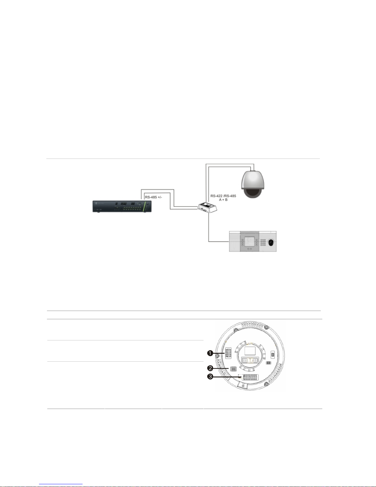
Connect a TVR 40 to a PTZ dome camera
Use the input/output box that is supplied with the TVK-505U keypad to connect both a PTZ dome
camera and a keypad to the TVR 40. See Figure 5 below.
Figure 5: Connecting a TVR 40 to a PTZ dome camera
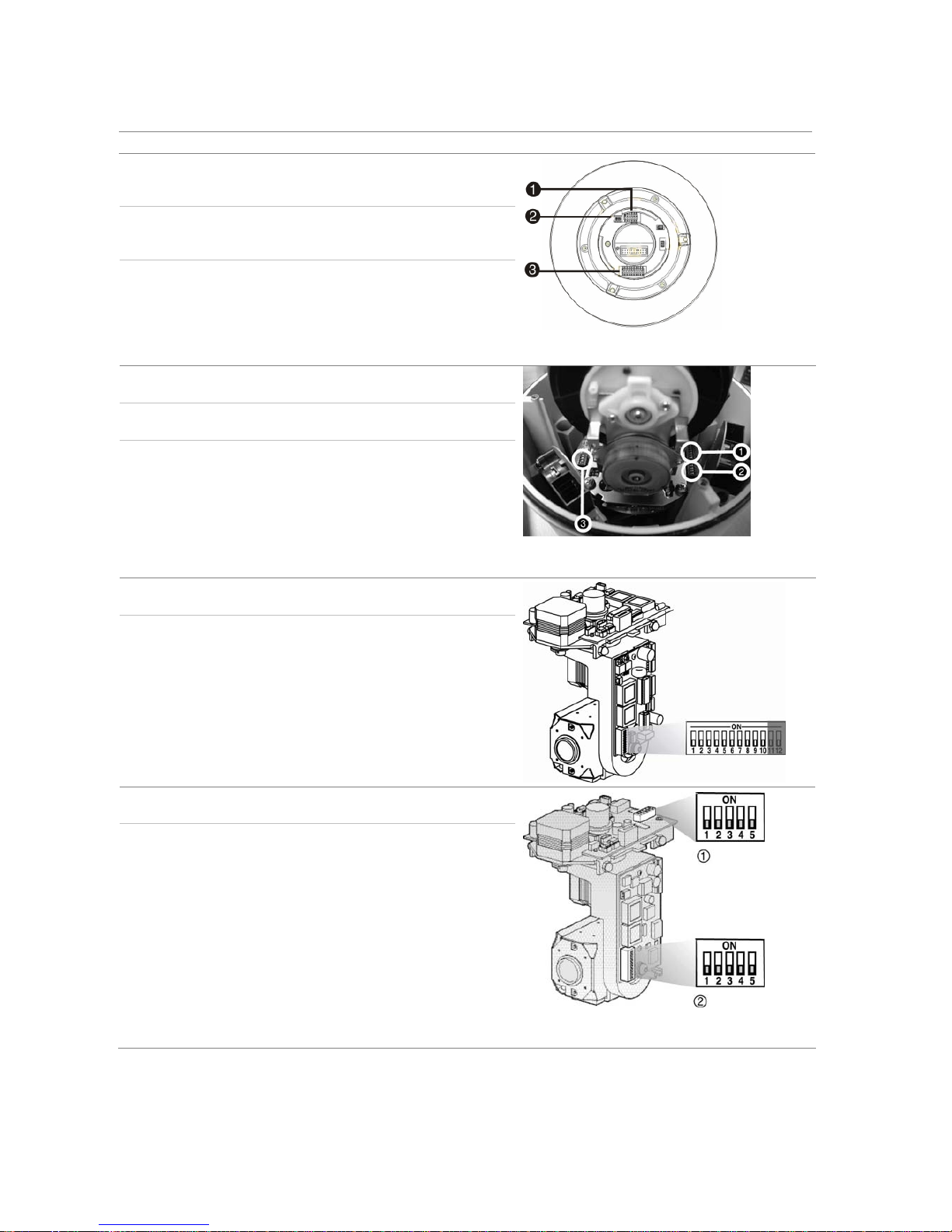
Configure the PTZ protocols for GE Security cameras
Before the PTZ cameras are assembled in their housings, set their protocol and address DIP switches
for the TVR 40. See Table 1 below for the different GE Security’s
PTZ camera configurations.
If you are using PTZ cameras from another company, please refer to their configuration instructions.
Table 1: Configuring GE Security PTZ cameras
Camera Switch setting
TruVision Dome
12X PTZ: Indoor
Dome
Protocol DIP
switches
000000
RS-485
communication DIP
switches
0000000000
Camera ID DIP
switches
0000
1. Protocol DIP switches; 2. RS-485 communication
DIP switches; 3. Camera site ID DIP switches
6 TruVision DVR 40 User Manual
Camera Switch setting
TruVision Dome
12X PTZ: Outdoor
Dome
Protocol DIP
switches
000000
RS-485
communication DIP
switches
0000000000
Camera site ID DIP
switches
0000
1. Protocol DIP switches; 2. RS-485 communication
DIP switches; 3. Camera site ID DIP switches
TruVision Dome 16
PTZ
Protocol DIP
switches
1011
Address DIP
switches
0000
Baud rate 0000
1. Address switches; 2. Baud switches; 3. Protocol
switches
CyberDome Protocol DIP
switches
Auto
Address DIP
switches:
0000000000
CyberDome II
Protocol DIP
switches
0000
Address DIP
switches:
0000
1. Protocol switches; 2. Address switches
TruVision DVR 40 User Manual 7
Camera Switch setting
Legend Protocol DIP
switches
5
Address DIP
switches:
0000
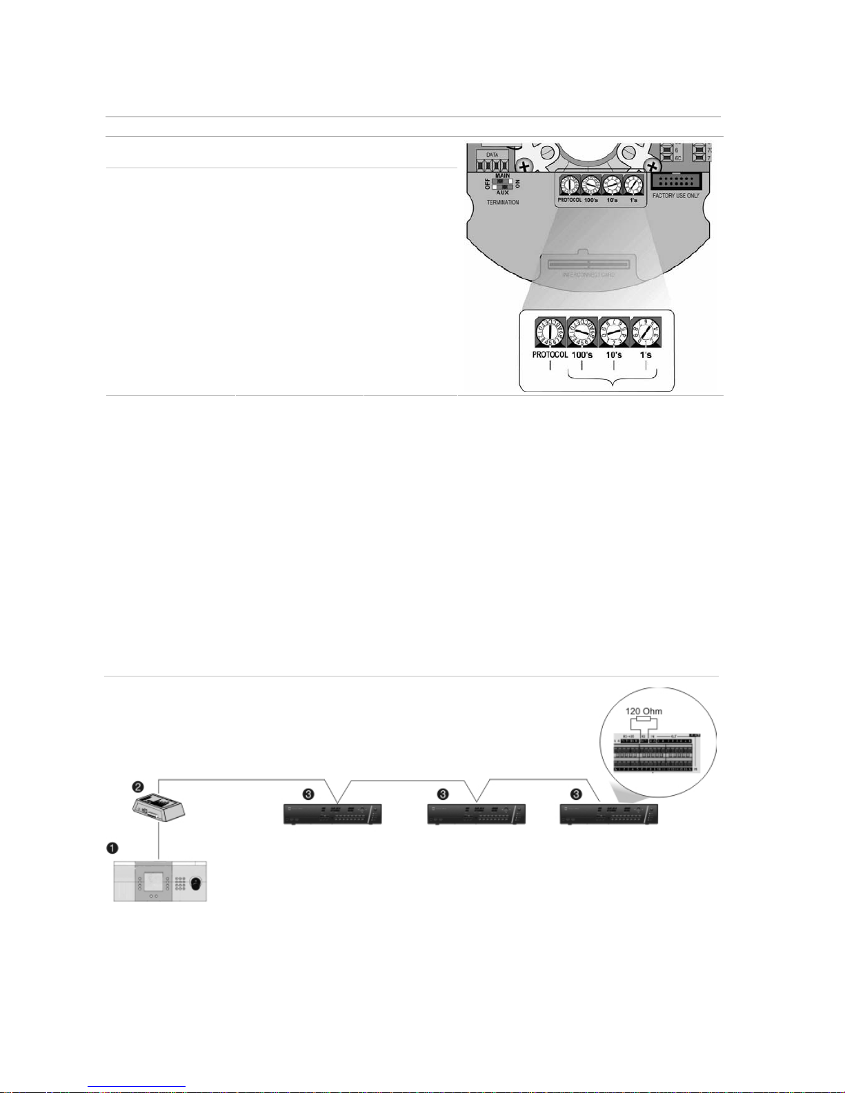
Wiring the TVK-505U keypad
The TVK-505U keypad uses RS-485 simplex wiring. The signal is transferred by a single twisted pair
line. An unshielded CAT5 network cable is recommended for normal applications. Use a shielded CAT5
cable if the cables could be exposed to interference.
The maximum number of TVR 40s that can be installed in one bus is 31, with a maximum cable length
of 1200 m. Both can be expanded using a signal distributor.
Both the first and the last device in series should be terminated with 120 Ohm resistance to minimize
line reflections. See Figure 6 below.
Figure 6: RS-485 bus serial wiring
1. TVK-505 keypad; 2. I/O box; 3. TVR 40

8 TruVision DVR 40 User Manual
Monitor connections
Connect the unit to the monitors via 75-ohm video coaxial cables with BNC connectors. The unit
provides a 1 Vpp CVBS signal.

TruVision DVR 40 User Manual 9
3. Controlling the TVR 40
There are four ways to control the TVR 40 menu options:
Front panel control
IR remote control
Mouse control
Web browser control
These options are described in the following sections.
10 TruVision DVR 40 User Manual
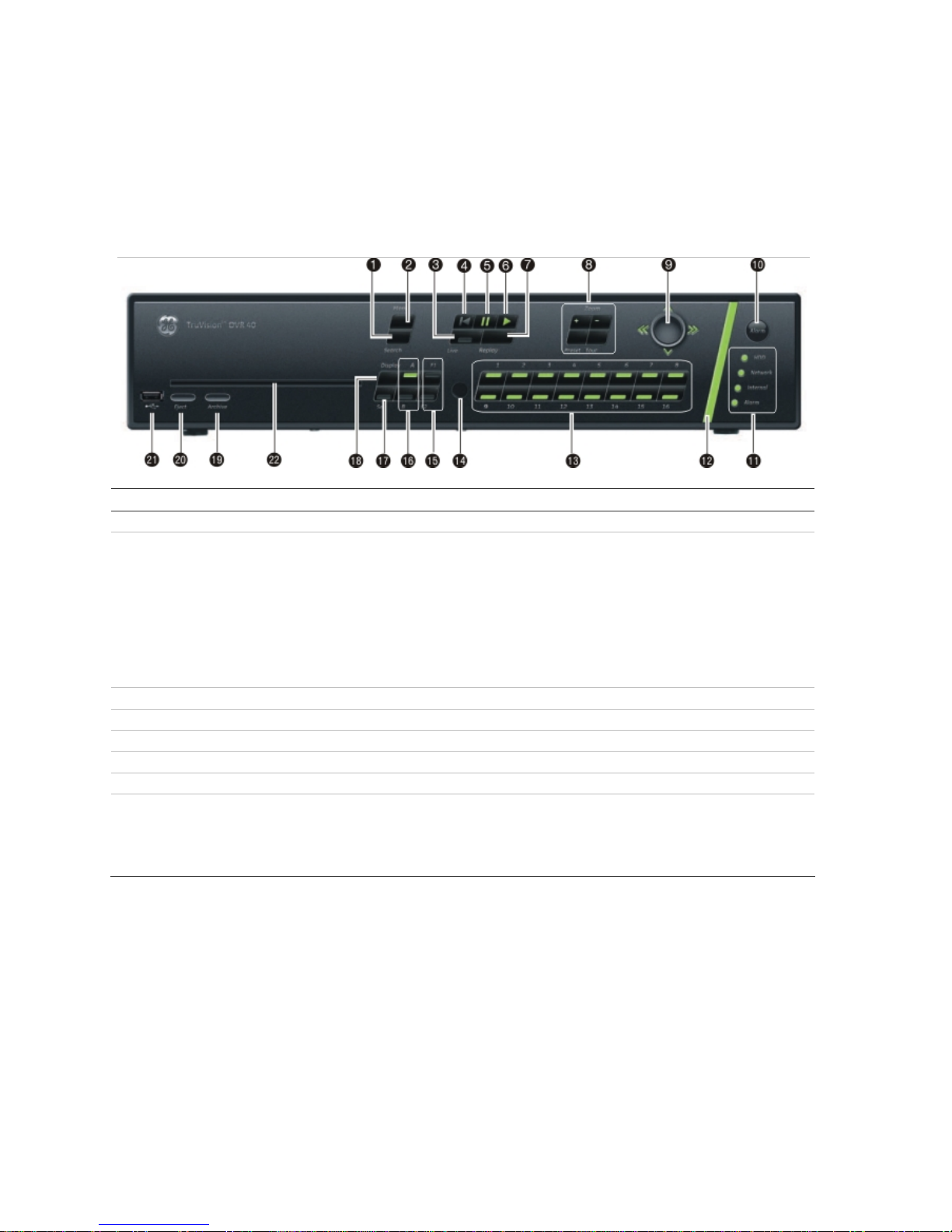
Using the front panel
The buttons on the front panel control all functions. The LED indicators light up or flash to alert you to
various conditions. The functions available can be limited by setting passwords. See Figure 7.
Figure 7: Front panel
Item Name Description
1. Search Press to open the Playback menu to search for and playback recorded videos.
2. Menu This button has several functions depending on the operation used.
In Live mode:
Press to open the Main menu.
In menu mode:
If an edit box of a menu option is selected, press the button to exit the option.
If a check box or list box of a menu option is selected, press the button to exit the
option and return to the Main menu. Press again to return to live mode. Any
changes made will not be saved.
3. Live Press to return to live mode.
4. Playback Press to playback the oldest file in the system.
5. Playback Pause Press to pause playback.
6. Instant Playback Press to playback the most recent three minutes of video recorded.
7. Replay Press to playback current file.
8. PTZ Control Displays the PTZ control of the selected camera, if PTZ is supported.
Zoom +/-: Press to zoom camera image in and out.
Preset: Select a pre-programmed Preset option.
Tour: Select a pre-programmed Shadow Tour option.

TruVision DVR 40 User Manual 11
Item Name Description
9. Trigger-point joystick Use to select options in a menu and to control playback. Press for Enter. LED
arrows are lit when the jog is active.
In live mode:
Press to enter PTZ mode.
In menu mode:
Move the joystick left/right and up/down to position cursor in menu screen. Press
for Enter.
In PTZ mode:
Move the joystick left/right and up/down to position cursor in menu screen. Press
for Enter.
In playback mode:
Rotate the joystick to control the movement of the PTZ camera.
Move left: Decrease speed.
Move right: Increase speed.
Move up: Jump forwards 30 seconds.
Move down: Jump backwards 30 seconds.
10. Manual Alarm Press to manually acknowledge an alarm.
11. Status LEDs HDD: Green – Hard drive is working correctly.
Red – Fault.
Network: Green – Network working correctly.
Red – Fault.
Internal: Green – Device is working correctly.
Red – There are internal errors.
Alarm: Green – No external alarm.
Red – indicates an external alarm status.
12. Alarm indicator Flashes red when there is an alarm.
13. Cameras Each camera has its own numeric button.
No light - Camera is disabled.
Green - Connected and working correctly
Red (flashing) - Camera is in alarm mode.
Red (steady) - Video loss.
14. IR remote receiver This is the receiver for the IR remote control.
15. F1 / F2 Press to select F1 or F2 functions. The functions vary depending on the operation
used such as:
- Select displayed time format.
- Archive recordings or specific segment of a recording.
- Select motion detection and privacy mask zones on-screen.
16. Monitor selection Press to toggle between monitors A and B.
17. Seq Press to sequence cameras in live mode.
18. Display Press to view multiscreen format.
19. Archive Press to open the Search Archive menu.
20. Eject Push to eject CD-ROM from the drive.
21. USB Insert USB device such as a mouse or storage media.
22. DVD slot Insert CD or DVD disk.
12 TruVision DVR 40 User Manual
To silence the audible button feedback
At any time press and hold down the Menu button for at least
five seconds. The audible button
feedback will activate or deactivate depending on the current status. Press Menu to return to live
mode.
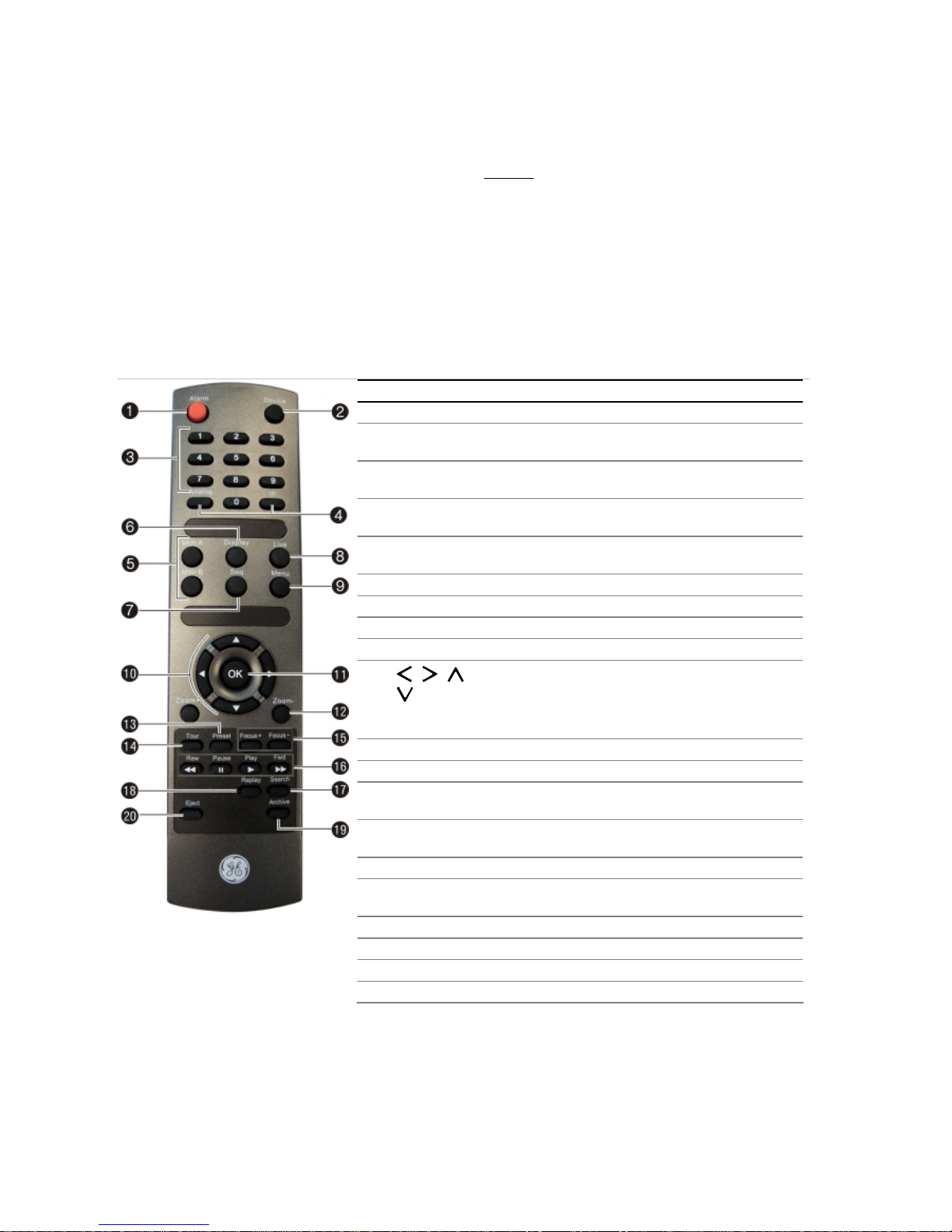
Using the IR remote control
The IR remote control operation is similar to the front panel operation.
Figure 8: Description of the IR remote control
Item Description
1. Alarm Acknowledge an alarm.
2. Device Enable/disable the IR remote control to control the
TVR 40.
3. Numeric
buttons
Select a camera, and enter a number in a menu
option.
4. Analog and IP Analog is equivalent to FI, and IP to F2, on the front
panel.
5. Mon A and
Mon B
Toggle between monitors A and B.
6. Display Toggle between the multiscreen views.
7. Seq Start /stop sequencing.
8. Live Return to live mode.
9. Menu Activate the main menu.
10. , , ,
In Menu mode: Use left or right arrow buttons to select
and up or down arrow buttons to edit entry.
In PTZ mode: Use to control PTZ.
In Playback mode: Use to control playback speed.
11. OK
Confirm selection.
12. Zoom + and - Use to control zoom of camera lens.
13. Preset Enter preprogrammed three-digit code to call up a
preset.
14. Tour Enter preprogrammed three-digit code to call up
shadow tour.
15. Focus + and - Use to control focus of camera lens.
16. Playback
control
Use to control playback (Rewind, Pause, Play, and Fast
Forward).
17. Search Open the Search menu.
18. Replay Replay the selected file from the beginning.
19. Archive Open the Quick Archive menu.
20. Eject Eject the CD or DVD disk.
To insert batteries into the IR remote control
1. Remove the battery cover on the IR remote control.
2. Insert the batteries. Observe the correct battery polarity (+ and -).
3. Replace the battery cover.

TruVision DVR 40 User Manual 13
To connect the remote control to the TVR 40
1. Press the Device button on the IR remote control.
2. Enter the device ID. The TVR 40 default ID is 1.
Note: See “Setting the device ID” on page 38 for information on how to change the device ID.
To disconnect the IR remote control
1. Press the Device button on the IR remote control. It cannot now be used to operate the DVR.
When the IR remote control does not function properly
Check the battery polarities
Check that the batteries are sufficiently charged
Check that the IR remote control sensor is not masked
If the problem persists, please contact your local supplier.
Using the mouse
Use the USB mouse provided with the TVR 40. It can carry out the same operations as the front panel
and remote control.
Connect the mouse to the DVR by simply plugging the mouse USB connector into one of the USB
ports on the TVR 40. The mouse is immediately operational.
To use the mouse in live mode
Scroll forwards and backwards between cameras: When in full-screen mode use the scroll
button on the mouse to scroll forwards and backwards through the cameras.
Toggle between full-screen and multiview: When in multiview double-click the left button of the
mouse on a camera to open it in full-screen view. Double-click again to return to multiview.
To access the mouse control menu
In live mode right-click the mouse to open its control menu. It has eight menu options, which are
listed in Table 2.
Table 2: Mouse control menu
Menu option Description
Menu Jump to the main menu.
Camera Select a specific individual camera.
Multi Screen Select multiview. The multiview selection presented depends on the number of cameras
connected to the TVR 40.
PTZ Control Control a PTZ camera. See Table 4 on page 30 for the description of the PTZ control icons.
Right-click the mouse to get the following options:
• Channel: Select the camera to control
• Preset: Select a preset number to use
• Exit: Return to live mode
14 TruVision DVR 40 User Manual
Menu option Description
Instant Replay Get an instant replay of the last five minutes recorded from all cameras in either full-screen
view or multiview. See section ““Playback recorded video” on page 25 for more information.
During the playback right-click the mouse to jump to the Playback menu.
Search Jump to the Playback menu. See “Searching and playing back recorded video” on page 21.
Select for recordings with specific criteria, such as particular camera, type of event, time,
and text.
Right-click the mouse to return to live mode.
Manual Record Manual Record menu screen appears. See “Manual recording” on page 20.
Status Bar Toggle the on-screen status bar on/off.
Swap Monitor Toggle between monitors A and B.
Using the Web browser
The TVR 40 Browser lets you easily view, record, and playback video as well as manage all aspects of the
system from any Internet location. It has easy-to-use controls that give you quick access to the functions you
require. See Figure 9 below for the layout.
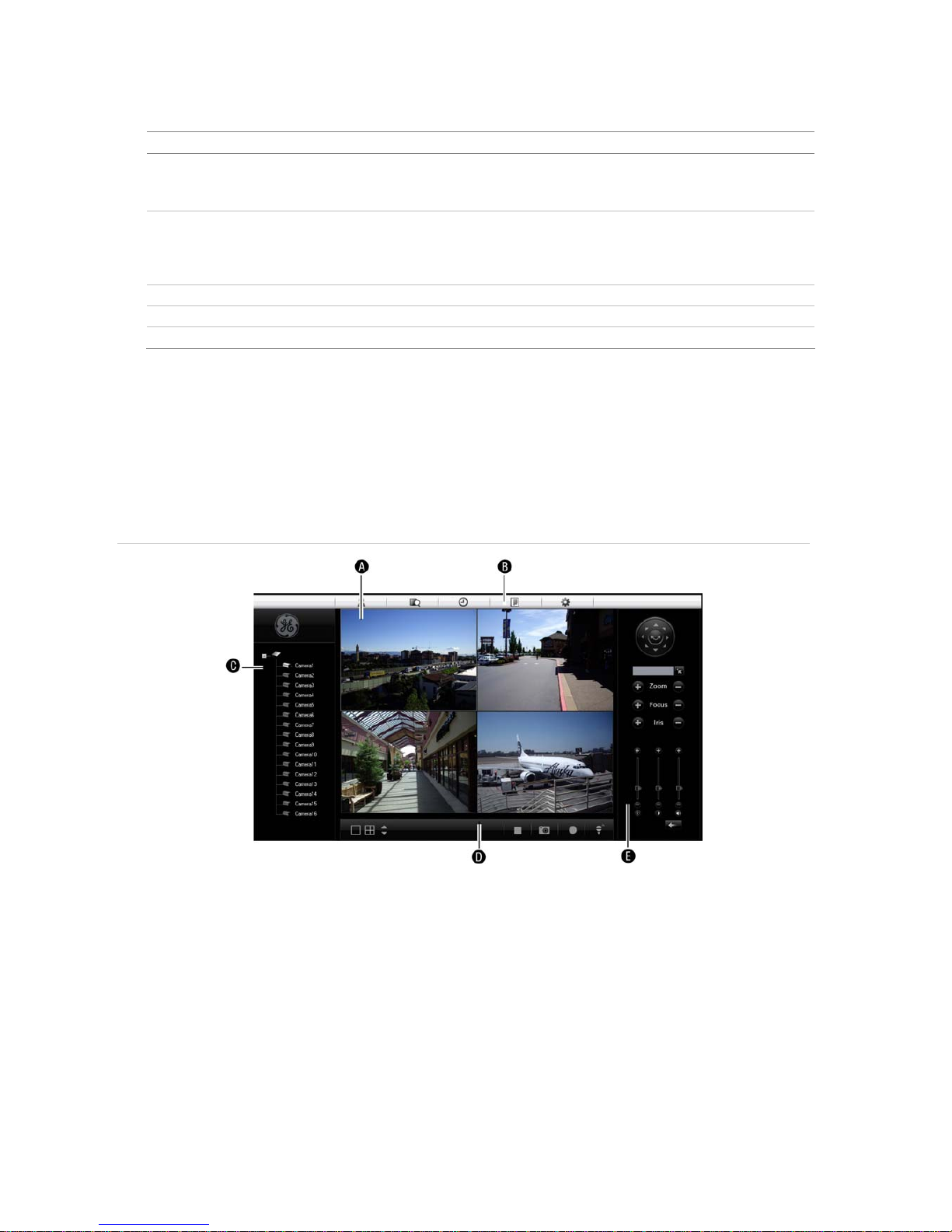
Figure 9: TVR 40 Browser layout (Live mode shown)
A. Viewer: View live and recorded video.
B. Navigation bar: Access live and playback video. Explore the TVR 40 internal log, and carry out comprehensive
remote maintenance.
C. Navigator: Access all TVR 40 cameras.
D. Viewer controller: View or edit the properties of the currently selected objects in the Navigator.
E. Camera controller: Control PTZ cameras or edit properties of the currently selected cameras.

TruVision DVR 40 User Manual 15
To access the TVR 40 Browser
Open Internet Explorer and type the IP address assigned to the TVR 40. In the Login screen enter the
user ID and PIN.
User ID = admin
PIN = 1234

16 TruVision DVR 40 User Manual
4. Basic operations
This chapter describes the everyday usage of the TVR 40. It explains:
Turning on the TVR 40
Login using PINs
Live mode
Full and multiscreen mode
Manual recording
Searching and playing back video
Archiving recorded files
Controlling a PTZ camera
Overview of the menu structure
Turning off the TVR 40
Turning on the TVR 40
The TVR 40 is delivered with preconfigured settings. You only need to connect at least one camera
and monitor. After powering up, the TVR 40will start to record immediately.
Note: The default video standard is PAL. For information on changing the standard, see section ““Selecting video
standard” on page 39.
The TVR 40 is equipped with a universal power supply that will auto-sense 100/240 V, 60/50 Hz.
Turn on the connected equipment. When you turn on the TVR 40 it automatically displays all
connected cameras. The TVR 40 shows the number of HDDs installed then displays live mode from
each connected camera. It automatically begins recording.
To get the unit into operation quickly
1. Connect all the devices required to the back panel of the TVR 40. See Figure 2 on page 3.
2.
Turn on the unit. The unit automatically carries out a diagnostic test of the devices. The video
images then appear on-screen.
3. To modify the preconfigured settings, press the Menu button on the front panel to access the
main menu. The login dialog screen appears.

TruVision DVR 40 User Manual 17
4. Enter the default administrator user ID and PIN. The main screen appears.
User ID = admin
PIN = 1234
5. Modify the TVR 40 parameters as required in the submenus.
6. When customization is complete, press the Menu button until live mode appears.
Logging in using PINs
Use PINs to limit access to the TVR 40. Only authorized users should be able to modify menu settings
or carry out certain tasks. For further information on managing users, see section “User settings” on
page 87.
Note: You will hear an aud
ible warning when an incorrect user name or PIN is entered. After three
incorrect entries, the unit returns to live mode.
Live mode
Live mode is the normal operation of the unit where you watch live pictures from the cameras. The
TVR 40 automatically enters live mode when powered up. From live mode you can switch to playback
mode or to the system menu.
The way the monitors display video depends on how you have set up the system.
In live mode the TVR 40 displays the status of each video channel at the bottom of the screen. See
Figure 10 on page 18. The number of channels displayed (4, 8,
or 16) depends on the TVR 40 model.

18 TruVision DVR 40 User Manual
Figure 10: Example of live mode with recording status displayed (for 16 cameras)
The monitor is inactive if the letter is grey
Caution: TVR 40 has no camera autodetection mode. The unit records a channel even if no camera is
connected to it. A black picture with the message "Video Loss" is displayed when the channel is
selected in either live mode or playback mode.
The color of the camera numbers displayed in the status bar represents the channel status. It is
consequently easy to see the current status of each channel during live mode. The status color code
is described in Table 3.
Table 3 Description of the status color code
Icon Icon color Status description
1
Blue No video signal
1
Yellow Camera tampered
1
Grey Recording disabled
1
Green Real time recording
1
Orange Motion detection
1
Red External alarm
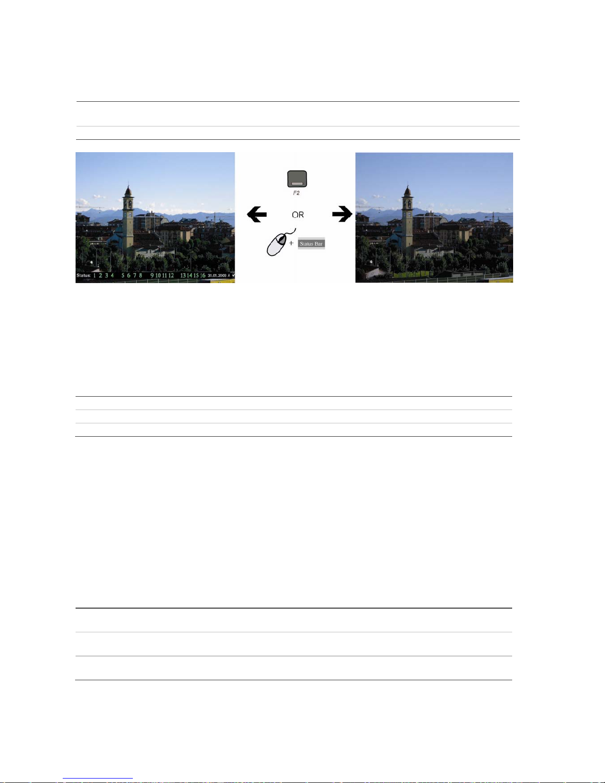
The status bar can be set to appear by default. See “Displaying the status bar” on page 38.
TruVision DVR 40 User Manual 19
To activate/deactivate the on-screen status bar
Front panel/remote control Press the F2 button on the front panel to activate or deactivate the status bar.
Mouse Right-click the mouse and select Status Bar from the menu.
Selecting a monitor
The TVR 40 can be connected to up to two monitors. However, only one monitor can be controlled at
a time. You can select from which monitor to display the camera views in live mode.
To switch between monitors A and B
Front panel Press buttons A or B to switch between monitors A and B.
IR remote control Press buttons Mon A or Mon B to select between monitors A and B.
Mouse Right-click the mouse and select Swap Monitor from the menu shown.
Viewing in multiscreen
The 16-channel TruVision DVR 40 User Manual has five multiscreen display formats available
including full screen. The eight-channel TruVision DVR 40 User Manual has four multiscreen display
formats.
A cameo is any cell in a multiscreen display. A camera picture can only be shown in one cameo at a
time. To change the order of cameras in the cameos, see “To setup multiscreen and dwell time” on
page 41”.
T
o view a full screen display
Front panel Press the numeric button that corresponds to the camera number. For example,
press button 10 to preview camera number 10.
IR remote control Press two number buttons that corresponds to the camera number. For example,
press buttons 0 and 2 to preview camera number 02.
Mouse Right-click the mouse and select Camera from the menu shown. Select the camera
required.

20 TruVision DVR 40 User Manual
To view a multiscreen display
Front panel/ IR remote control Press the Display button to switch to multiscreen live mode. If the multiscreen
display does not include all the cameras required, keep pressing the Display button
to increase the number of screens displayed.
Mouse Right-click the mouse and select Multi Screen from the menu. Select the desired
multiscreen display layout.
To manually cycle through live mode
Front panel/ IR remote control Press the Seq button to manually step through the live modes. You can set the auto
multiscreen mode in the Display menu. See section “Multiscreen and sequencing”
on page 41 for further informati
on.
Mouse Use the mouse wheel to scroll forwards and backwards through the live modes.
Manual recording
When a channel is recording, its corresponding camera LED on the front panel is green. This
recording status is also repeated in the Manual Record menu.
Manually start or stop a channel recording from the Manual Record menu. This menu is only
accessible using the mouse.
What the status options mean in the Manual Record menu
When the status of the camera number is:
• Green: Indicates the channel is recording
• Red: Indicates remote viewing
• Orange: Indicates both recording and remote viewing
• Grey: Indicates the channel is not recording
Start/Stop options:
• : Indicates recording is enabled

TruVision DVR 40 User Manual 21
To manually start or stop a recording
1. Right-click the mouse and select the option Manual Record. Enter your user name and PIN, if
requested.
Note: You must have Record rights to change the manual recording status. See “Modifying operational
rights” on page 90 for more
information.
The Manual Record screen appears. All channels are listed. The Camera line shows the channels
that are currently recording. In the example below, 13 of the 16 channels are recording.
2. On the Start/Stop line activate or deactivate a channel by press Enter or left-click the mouse to
activate () a channel that is not recording. Press or click again to de-activate.
The camera status LED on the front panel, and the camera number in the status bar on-screen in
live mode, turn green.
3. Select the next channel from which you want to start or stop recording.
4. If you want all channels to start recording, select Start All. All the channel status LEDs on the front
panel and the on-screen camera numbers in the status bar turn green.
Select Stop All to switch off all channels.
5. Press the Menu button on the front panel, or right-click the mouse, to save changes and return to
live mode.
Searching and playing back recorded video
The TVR 40 lets you quickly search and playback recorded video. You must be in live mode to
playback video. See Figure 11 on page 22.
22 TruVision DVR 40 User Manual
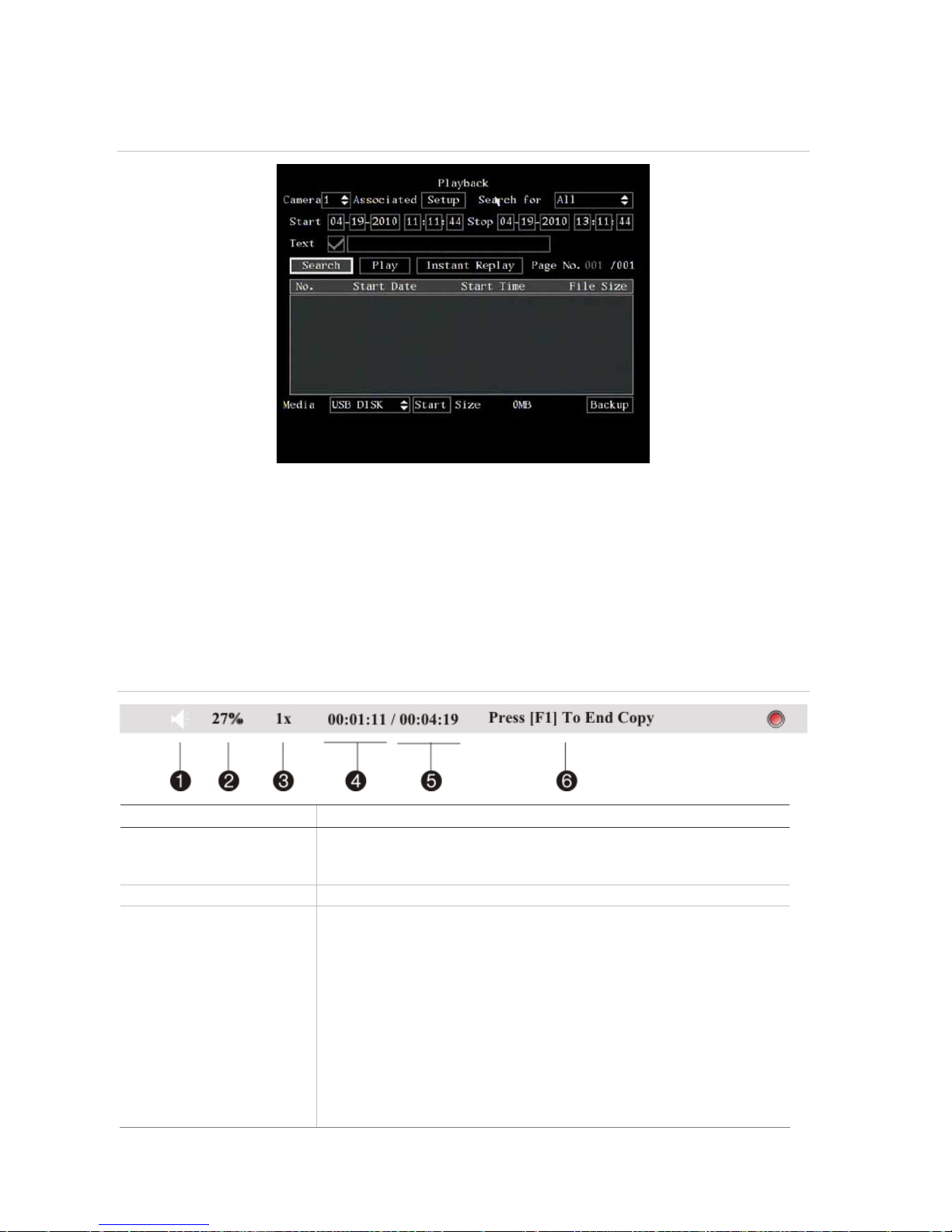
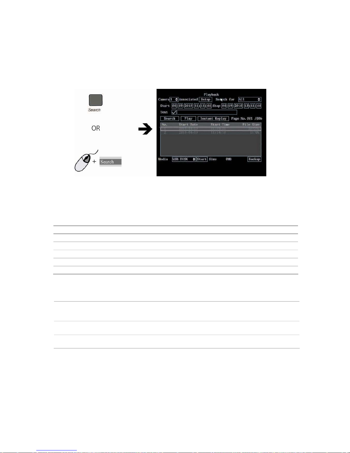
Figure 11: Playback screen
Note: You must have playback rights to playback recorded images. See “Modifying operational rights” on page
90 for more information.
The system also lets you playback channels simultaneously so that multiple images appear onscreen.
Control playback progress
When in playback mode a status bar appears on-screen during playback to show playback progress
and speed. See Figure 12 below.
Figure 12: Playback status bar
Option Description
1. Audio Press PLAY to silence the audio recording associated with this video. Press PLAY
again to reactivate the audio.
Audio in this example is on.
2. Playback progress Shows how far you have progressed through the recorded file.
3. Playback speed Move the joystick left or right to change the rate of playback. Nine options are
available:
Single: Advance one frame at a time.
1/8x: An eighth of actual speed.
1/4x: Quarter of actual speed.
1/2x: Half of actual speed.
1x: Actual speed.
2x: Twice actual speed.
4x: Four times actual speed.
8x: Eight times actual speed.
MAX: Maximum speed.
TruVision DVR 40 User Manual 23
Option Description
4. Current playback time Playback always starts from time zero. The actual time of the recording is shown
on the top of the screen.
Move the joystick up to jump forwards 30 seconds. It is not possible to jump
backwards.
5. Total playback time Shows the duration of the recorded file. In this example, it is 4 minutes 19
seconds.
6. Start/end copy Press the F1 button to start or stop copy a segment of the playback video.
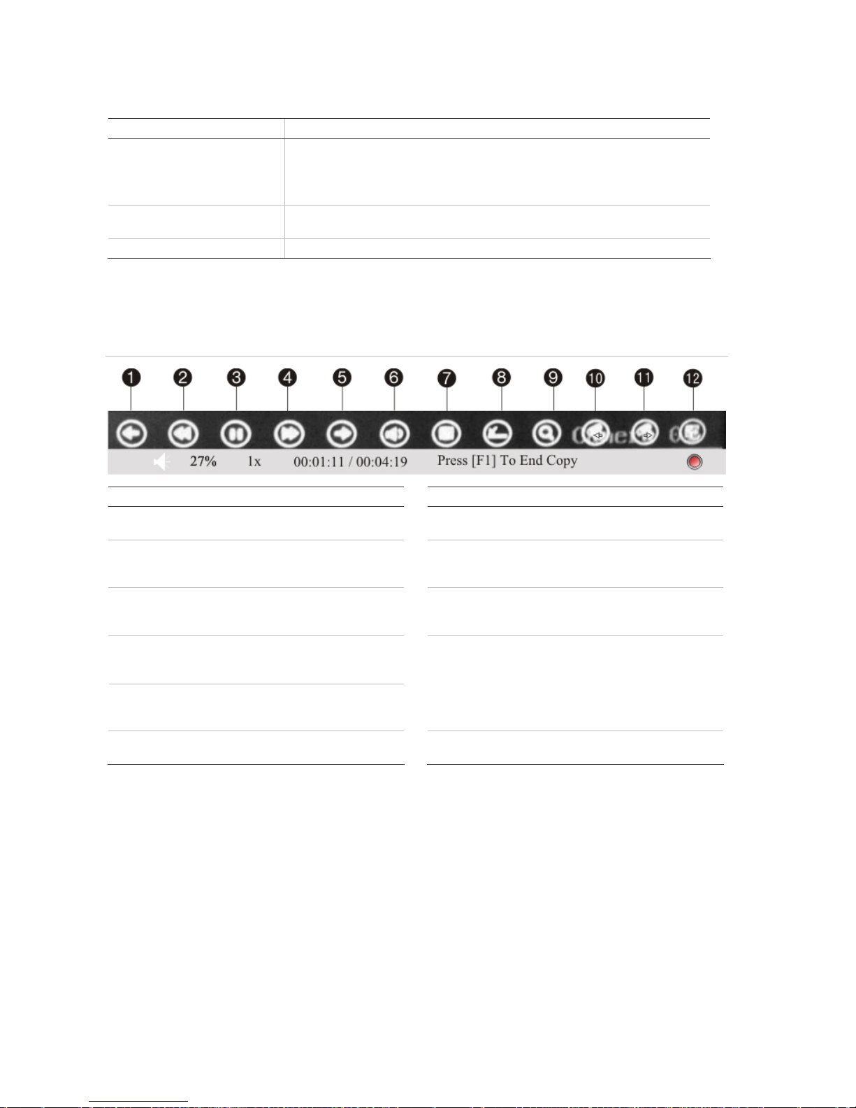
If a mouse is connected to the unit, a toolbar appears that allows you to control many playback
functions with the mouse. See Figure 13 below.
Figure 13: Mouse playback toolbar
Item Description
Icon Description
1. Jump back 30 seconds in the playback
video.
7. Start archiving the video.
2. Decrease the playback speed. See
Figure 12 for the list of speeds
available.
8 Remove the Playback toolbar. To make it
reappear on-screen, right-click the mouse
and select Display.
3. Pause playback.
9. Digital zoom. Double left-click the mouse
to zoom in. Double left-click again to
return to normal view.
4. Increase the playback speed. See
Figure 12 for the list of speeds
available.
5. Jump forward 30 seconds in the
playback video.
10 &
11.
To view full screen when in multiscreen
mode, double-click the mouse on the
desired screen. It appears as full screen.
Left-click the mouse on one of the icons
to move backwards or forwards through
the full screens.
6. Turn on or off audio.
12. Left-click the mouse to scroll through the
number of multiscreens displayed.
Search recorded video
There are many different ways to search recorded videos, such as:
Recordings which have alarms or motion detection, or have been manually recorded
Start and end time and date of recording
Text (from an ATM, for example)
24 TruVision DVR 40 User Manual
To search for recorded video
1. In live mode press the Search button on the front panel of the TVR 40 or on the IR remote control,
or right-click the mouse and select Search. Enter your user name and PIN, if requested.
The Playback menu appears.
2. In the Camera list box select the channel you want to search.
3. To select more than one camera for playback, click the Associated Setup box. In the submenu that
appears, select the cameras required.
4. In the Search for list box select the type of recorded videos to be searched.
Option Search for recorded file types
All All recordings
All Time Only scheduled time recorded files
Manual Only manually recorded files
Alarm Only alarm recorded files
Motion Det. Only motion detected files
5. For the Start and Stop recording periods go to each edit box and enter the start and end dates
and times as follows:
Front panel Press the joystick to enter the edit box. Move the joystick up or down to scroll
through the numbers to select a number. Move the joystick left or right to move to
the next edit box.
IR remote control Use the arrows buttons to change the numeric value. Press Enter when completed
and move to the next edit box.
Mouse Click the edit box and select the number required from the on-screen numeric list
that appears.
Note: Date has the format DD-MM-YYYY. Time has a 24-hour format. The default stop values shown are the
current time and date.
6. To search for video from a particular ATM, for example, enable () the Text check box.
Using the mouse, select the edit box alongside the check box to enter the text to be searched (for
example, text that appears on an ATM screen.) An on-screen alphanumeric keyboard appears.
Click Shift to select the type of character required: Number, upper case letter, lower case, letter or
symbol. There are 24 symbols to select. Press 0 on the front panel to scroll between the four
pages of symbols available.
 Loading...