

GE TruVision DVR 20 User Manual

GE
Security
P/N 1069892-EN • REV 1.1 • ISS 31MAY10
TruVision DVR 20 User Manual
Copyright © 2010 GE Security, Inc.
This document may not be copied in whole or in part or otherwise reproduced without prior
written consent from GE Security, Inc., except where specifically permitted under US and
international copyright law.
Disclaimer
The information in this document is subject to change without notice. GE Security, Inc.
(“GE Security”) assumes no responsibility for inaccuracies or omissions and specifically disclaims
any liabilities, losses, or risks, personal or otherwise, incurred as a consequence, directly or
indirectly, of the use or application of any of the contents of this document. For the latest
documentation, contact your local supplier or visit us online at www.gesecurity.com.
This publication may contain examples of screen captures and reports used in daily operations.
Examples may include fictitious names of individuals and companies. Any similarity to names
and addresses of actual businesses or persons is entirely coincidental.
Trademarks and patents
GE and the GE monogram are trademarks of General Electric Company. The TruVision is a
trademark of GE Security.
Other trade names used in this document may be trademarks or registered trademarks of the
manufacturers or vendors of the respective products.
Intended use
Use this product only for the purpose it was designed for; refer to the data sheet and user
documentation for details. For the latest product information, contact your local supplier or visit
us online at www.gesecurity.com.
Certification and compliance
European Union directives
2004/108/EC (EMC directive): Non-European manufacturers must designate an authorized
representative in the Community. Our authorized manufacturing representative is:
GE Security B.V., Kelvinstraat 7,
6003 DH Weert, The Netherlands.
2002/96/EC (WEEE directive): Products marked with this symbol cannot be disposed of as
unsorted municipal waste in the European Union. For proper recycling, return this product to
your local supplier upon the purchase of equivalent new equipment, or dispose of it at
designated collection points. For more information see: www.recyclethis.info.
2006/66/EC (battery directive): This product contains a battery that cannot be disposed of as
unsorted municipal waste in the European Union. See the product documentation for specific
battery information. The battery is marked with this symbol, which may include lettering to
indicate cadmium (Cd), lead (Pb), or mercury (Hg). For proper recycling, return the battery to your
supplier or to a designated collection point. For more information see: www.recyclethis.info.
Contact information For contact information see our Web site: www.gesecurity.eu.

TruVision DVR 20 User Manual i
Content
Chapter 1 Product introduction 1
Product overview 1
Features 2
Chapter 2 Installation 5
Installation environment 5
Unpacking the TVR 20 and its accessories 5
HDD capacity 6
Connecting devices to the rear panel 7
Alarm inputs and outputs 8
Camera inputs 9
RS-485 port 9
RS-232 port 10
PTZ dome camera set up 10
Wiring the KTD-405 keypad 13
Using the KTD-405 keypad to address PTZ cameras in zone mode 16
Monitor connections 17
Audio inputs and output 17
Chapter 3 eZ setup 19
Chapter 4 Operating instructions 23
Control interfaces 23
Controlling the TVR 20 23
Using the front panel 24
Using the mouse 26
Using the remote contr
ol 27
Using a KTD-405/KTD-405-2D keypad 29
Screen overview 31
Chapter 5 Basic operation 35
Turning on the TVR 20 35
Logging on 35
TVR 20 toolbar overview 36
Live mode 37
Controlling a PTZ camera 43
Playing back recorded video 46
Bookmarking recorded video 49
Archiving recently recorded video 50
Searching and playing back recorded video 53
Playing back archived files on a PC 59
Manually acknowledging an alarm 59
Logging off from setup mode 59

ii TruVision DVR 20 User Manual
Turning off the TVR 20 59
Chapter 6 Advanced setup 61
Overview of the Menu toolbar 61
Camera settings 62
Alarm and event settings 72
Schedule settings 79
Network settings 84
Display settings 89
Managing users 91
System setup 94
System information 102
Chapter 7 Web browser 103
Web browser overview 104
Searching recorded video 105
Playing back and archiving recorded video 106
Windows Vista and 7 users 108
Chapter 8 eZ DDNS 111
Chapter 9 Troubleshooting 113
Appendix A Specifications 115
Appendix B Warranty and support 117
Index 119
TVR 20 menu map 122

TruVision DVR 20 User Manual 1
Chapter 1
Product introduction
Product overview
This is the TruVision DVR 20 User Manual for models:
• TVR-2004-500EA
• TVR-2004-1TEA
• TVR-2008-500EA
• TVR-2008-1TEA
• TVR-2016-500EA
• TVR-2016-1TEA
The TruVision DVR 20 (TVR 20) digital video recorder generation is based on H.264
compression technology. It has enhanced recording capacity and improved network
image transmission speed with high image quality. Comprehensive features and
extended event recording settings enable the almost universal application of this DVR
series.
With Graphical User Interface (GUI), users can command specific actions on the
TVR 20 through graphical icons and visual indicators. Simply point, click, and drag the
playback bar on the screen to playback the recordings in any time slot.
There are multiple control inputs, which include mouse control, front panel control,
remote control, and keypad (KTD-405/KTD405-2D) control. Mouse control is
supported with the simple GUI, offering experienced PC users the similarity of
interactive command of a computer-controlled device. All GUI functions can be
operated via front panel, IR remote, and keypad as well.
The TVR 20 is engineered for express operations. Setup, copy, search, and playback
recordings in seconds with a simple “point and click” on the command icons.

48BChapter 1: Product introduction
2 TruVision DVR 20 User Manual
Features
This section describes the available TVR 20 features.
Compression
The TVR 20 supports the following video features:
Pentaplex operation (simultaneous live, recording, playback, archiving and remote
viewing)
User friendly GUI with graphical icons and visual indicators
Real-time live display for all cameras
Simultaneous VGA, composite and S-video output
Storage
The TVR 20 supports the following storage features:
Two hot swappable HDD or four internal HDD
Built-in DVD burner
Supports eSATA
Two USB 2.0 ports (located on the front panel) for video archive and mouse usage
Preview and playback
The TVR 20 supports the following preview and playback features:
Built-in DVR calculator for fast recording estimation
Express setup: Located in menu option for quick and easy installation
Express copy: Record video instantly while playing back (USB)
Express Playback: Simply point, click and drag the playback bar to view previous
recordings
Express Search: Use intuitive playback bar with a simple drag & drop operation
Network
The TVR 20 supports the following network features:
Free eZ-DDNS Service
Remote configuration support from built-in web interface
Gigabit Ethernet interface for remote network viewing and controlling
On-screen PTZ control via mouse or front panel

48BChapter 1: Product introduction
TruVision DVR 20 User Manual 3
Other features
The TVR 20 supports the following additional features:
Auto-detect video mode (PAL or NTSC) on startup
Multiple Control Inputs: mouse/front panel/remote control
Audio recording capabilities*
Multi-language support
Watermark capabilities to identify intentional modifications of recorded data
Rack mountable
Support KTD-405/KTD405-2D keypad control
* Feature not available for all models.

48BChapter 1: Product introduction
4 TruVision DVR 20 User Manual

TruVision DVR 20 User Manual 5
Chapter 2
Installation
Installation environment
When installing your product, consider these factors:
• Ventilation
• Temperature
• Moisture
• Chassis load
Ventilation: Do not block any ventilation openings. Install in accordance with the
manufacturer’s instructions. Ensure that the location planned for the installation of
the unit is well ventilated.
Temperature: Consider the unit’s operating temperature (0 to 40°C, 32 to 104°F) and
noncondensing humidity specifications (10 to 90%) before choosing an installation
location. Extremes of heat or cold beyond the specified operating temperature limits
may reduce the life expectancy of the DVR. Do not install the unit on top of other hot
equipment. Leave 44 mm (1.75 in.) of space between rack-mounted DVR units.
Moisture: Do not use the unit near water. Moisture can damage the internal
components. To reduce the risk of fire or electric shock, do not expose this unit to rain
or moisture.
Chassis: Equipment weighing less than 15.9 kg (35 lb.) may be placed on top of the
unit.
Unpacking the TVR 20 and its accessories
When you receive the product, check the package and contents for damage, and
verify that all items are included. There is an item list included in the package. If any
of the items are damaged or missing, please contact your local supplier.
Items shipped with the product include:

49BChapter 2: Installation
6 TruVision DVR 20 User Manual
• IR (infrared) remote control
• Two AAA batteries for the remote control
• AC power cord
• USB mouse
• External power supply unit x 1 (Europe and UK)
• DVR
• TruVision DVR 20 Quick Start Guide
• TruVision DVR 20 User Manual (on CD)
HDD capacity
Storage capacity for the TVR 20 varies depending on the model. Refer to Table 1
below for more information.
Table 1: TruVision DVR 20 model types
Model number Description
TVR-2004-500EA TruVision DVR Model 20, 4 ch, 500 GB
TVR-2004-1TEA TruVision DVR Model 20, 4 ch, 1 TB
TVR-2008-500EA TruVision DVR Model 20, 8 ch, 500 GB
TVR-2008-1TEA TruVision DVR Model 20, 8 ch, 1 TB
TVR-2016-500EA TruVision DVR Model 20, 16 ch, 500 GB
TVR-2016-1TEA TruVision DVR Model 20, 16 ch, 1 TB

49BChapter 2: Installation
TruVision DVR 20 User Manual 7
Connecting devices to the rear panel
Figure 1 below shows the rear panel connections and describes each connector on a
typical TVR 20 digital video recorder. Details may vary for specific models.
Figure 1: Rear panel connections (16-channel model shown)
Required connections
1. Video inputs: Connect up to 16 cameras to the standard BNC video inputs.
2. Monitor A or VGA monitor (default): Connect the main monitor to one of the output connections
Optional connections
3. Audio outputs: Connect up to two audio outputs (depends on model) such as line level devices (for
example, speakers with built-in pre-amplifiers).
4. Audio inputs: Connect up to four to audio input (depends on model) such as microphones.
5. Monitor B: Connect a spot monitor (Mon B) to the spot monitor output. The VGA monitor must
support 800 x 600 Hz resolution.
6. RS-232 connector: Connect an RS-232 cable from a device such as a PC to the 9-pin D-sub input.
7. RS-485/RS-422 connector: For telemetry control or remote control via RS-485 keypads
8. Alarm input: Connect up to 16 dry contacts (depends on model). NO and NC supported.
9. Alarm output: Connect up to four NO/NC alarm output relays (depends on model).
10. LAN: Connect the network devices.
11. e-SATA: Connect the e-SATA for archive and storage expansion.
12. USB port: Insert USB devices. USB CD/DVD burner and USB HDD are not supported.
Power connection
13. Power socket: Connect the power cord to the TVR 20. Be sure that all devices are connected and
turned on before turning on the unit. Use the external power supply unit provided.

49BChapter 2: Installation
8 TruVision DVR 20 User Manual
Alarm inputs and outputs
Table 2: Number of inputs and outputs
4-channel TVR 20 4 external alarm inputs 1 internal alarm output
8-channel TVR 20 8 external alarm inputs 2 internal alarm outputs
16-channel TVR 20 16 external alarm inputs 4 internal alarm outputs
Alarm inputs
There is a pin connector on the rear panel to connect the alarm inputs. The number
of pins depends on the TVR 20 model. They can be wired normally open (NO) or
normally closed (NC). They are configured in section “Responding to an alarm” on
page 73.
Note: Do not attempt to wire any accessories di
rectly to the I/O connector on the rear
panel. These connections require dry contact (voltage free) closure to activate.
Figure 2: Programmable alarm inputs
Alarm input with NO in idle state Alarm input with NO in idle state
Alarm outputs
The four alarm output relays respond to input alarms and triggers. They can be
configured as NO or NC in section “Alarm and event notification” on page 75.
Table 3: Alarm output pins
Alarm out number Pin Description
Alarm out 1 1 NO (Normally Open)
2 C (Common)
3 NC (Normally Closed)

49BChapter 2: Installation
TruVision DVR 20 User Manual 9
Alarm out number Pin Description
Alarm out 2 1 NO (Normally Open)
2 C (Common)
3 NC (Normally Closed)
Alarm out 3 1 NO (Normally Open)
2 C (Common)
3 NC (Normally Closed)
Alarm out 4 1 NO (Normally Open)
2 C (Common)
3 NC (Normally Closed)
Figure 3: Alarm output relay in idle state
Camera inputs
Connect cameras to the TVR 20 using 75-ohm video coaxial cables with BNC
connectors. There are two BNC jacks for each camera. Either jack can receive a
camera signal. The signal is looped (directly connected to the other jack), making the
camera signal available to other equipment.
The camera input connectors are auto terminating. This means that the input signal
will automatically be terminated with 75-Ohms unless a second cable is connected to
the second BNC connector of the same camera input.
Make sure there is 75-Ohm termination at the end of the video line if the signal is
looped through the TVR 20.
RS-485 port
The RS-485 port is used for pan, tilt, zoom control of PTZ cameras as well as for
keypads. See “RS-232 and RS-485 port settings” on page 96 to configure this port. See
Figure 4 on page 10 for the serial pin outs for the configuration.

49BChapter 2: Installation
10 TruVision DVR 20 User Manual
Figure 4: RS-485 pins
RS-232 port
The RS-232 port is provided for use with GE's ProBridge text insertion interface
modules in conjunction with compatible CBR, PB3, POS (point of sale) and ATM
(automated teller machine) systems. See “RS-232 and RS-485 port settings” on page
96 to configure this port.
Table 4: RS-232 pins
Pin Description
2 TX
3 RX
5 Ground
PTZ dome camera set up
Use the USB mouse provided or the optional KTD-405 keypad for local telemetry
control. If using the TVR 20 over a network, use the web browser to control the PTZ
dome cameras.
The supported protocols are: GE, Pelco-D, and Pelco-P
For information on setting up the PTZ protocols and presets see “PTZ setup” on page
70 and “RS-232 and RS-485 port settings” on page 96.
Connecting a TVR 20 to a PTZ dome camera
Use the input/output box that is supplied with the KTD-405 keypad to connect both a
PTZ dome camera and a keypad to the TVR 20. See Figure 5 on page 11.

49BChapter 2: Installation
TruVision DVR 20 User Manual 11
Figure 5: Connecting a TVR 20 to a PTZ dome camera
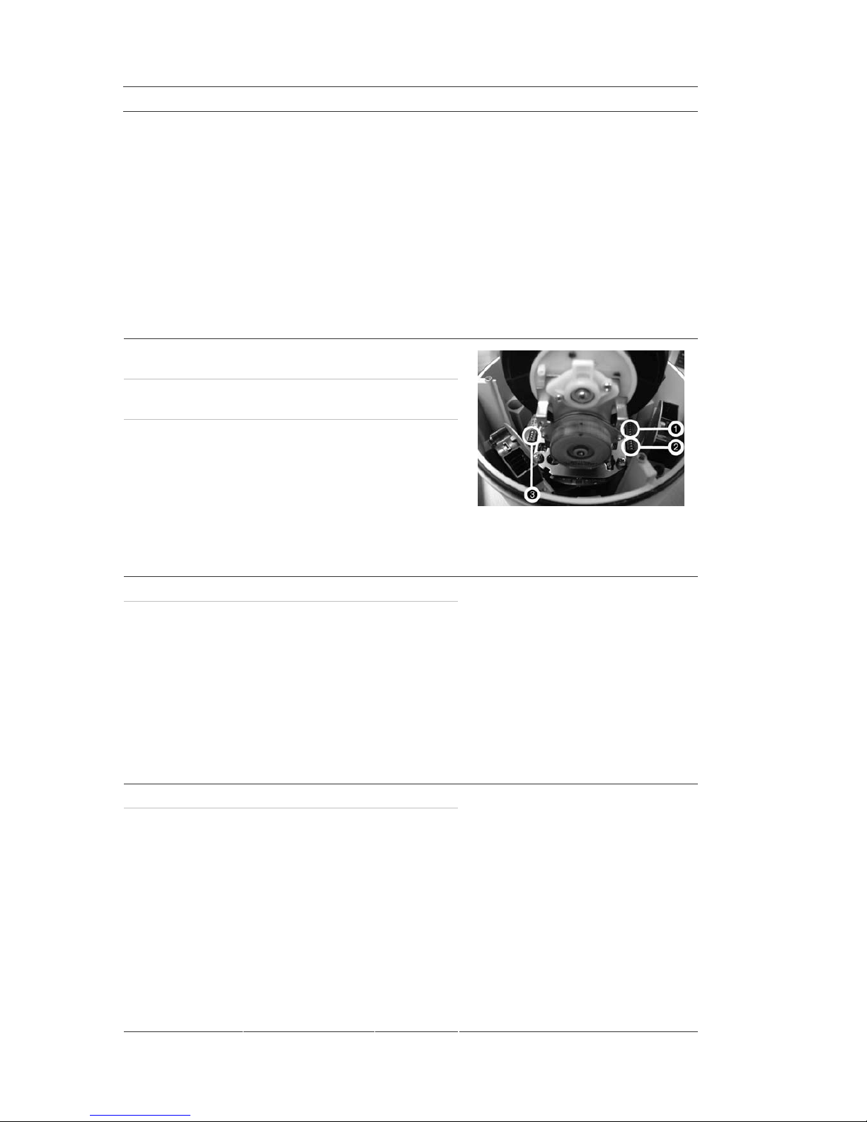
Configuring the PTZ protocols for GE Security cameras
Before the PTZ cameras are assembled in their housings, set their protocol and
address DIP switches for the TVR 20. See Table 5 below for different GE Security PTZ
camera settings.
If you are using PTZ cameras from another company, please refer to their
configuration instructions.
Table 5: PTZ protocols for GE Security cameras
Camera Switch setting
TruVision Mini PTZ
12X: Indoor Dome
Protocol DIP switches 000000
RS-485
communication DIP
switches
0000
Camera site ID DIP
switches
0000000000
1. Protocol DIP switches;
2. RS-485 communication DIP switches;
3. Camera site ID DIP switches
49BChapter 2: Installation
12 TruVision DVR 20 User Manual
Camera Switch setting
TruVision Mini PTZ
12X: Outdoor Dome
Protocol DIP switches 000000
RS-485
communication DIP
switches
0000
Camera site ID DIP
switches
0000000000
1. Protocol DIP switches;
2. RS-485 communication DIP switches;
3. Camera site ID DIP switches
TruVision Dome 16X
PTZ
Protocol switches 1011
Camera site ID
address switches
0000
Baud rate 0000
1. Address switches;
2. Baud switches;
3. Protocol switches
CyberDome Protocol switches Auto
Camera site ID
address switches
0000000000
CyberDome II Protocol switches 00000
Camera site ID
address switches
0000000000
1. Protocol switches;
2. Camera site ID address switches

49BChapter 2: Installation
TruVision DVR 20 User Manual 13
Camera Switch setting
Legend Protocol switches 5
Address switches 0000
Wiring the KTD-405 keypad
The KTD-405 keypad uses RS-485 simplex wiring. The signal is transferred by a single
twisted pair line. An unshielded CAT5 network cable is recommended for normal
applications. Use a shielded CAT5 cable if the cables could be exposed to
interference.
The maximum number of TVR 20s that can be installed in one bus is 31, with a
maximum cable length of 1200 m. Both can be expanded using a signal distributor.
Both the first and the last device in series should be terminated with 120 Ohm
resistance to minimize line reflections. See Figure 6 below.
Figure 6: RS-485 bus serial wiring
1. KTD-405 keypad
2. I/O box
3. TVR 20
The cable length from box to device cannot exceed 2 m when using connector boxes.
See Figure 7 on page 14.

49BChapter 2: Installation
14 TruVision DVR 20 User Manual
Figure 7: RS-485 bus serial wiring with connector boxes
1. KTD-405 keypad
2. I/O box
3. TVR 20
4. Connector box
Use an RS-485 signal distributor for a star wiring configuration. See Figure 8 below.
Figure 8: Star wiring with RS-485 signal distributor
Correct
1. KTD-405 keypad
2. I/O box
3. TVR 20
4. RS-485/KTD-83 distributor

49BChapter 2: Installation
TruVision DVR 20 User Manual 15
Incorrect
Use an RS-485/KTD-83 signal distributor to increase the maximum number of devices
on the bus as well as the total range. Each distributor output provides another RS485 bus, extending the output an additional 1200 m. Up to 31 TVR 20s can be
connected to each output. See Figure 9 below.
Figure 9: Expanding the system with an RS-485 signal distributor
Caution: Most signal distributors are unidirectional. This means that the signal only
flows from the input towards the outputs. Consequently it is not possible to connect
several keypads.
See “RS-232 and RS-485 port settings” on page 96 to configure the RS-485 port
communication settings.

49BChapter 2: Installation
16 TruVision DVR 20 User Manual
12BUsing the KTD-405 keypad to address PTZ
cameras in zone mode
The KTD-405 keypad can programmed to operate in zone mode which allows you to
use several DVRs and cameras. A zone is a remote switching device, such as a DVR,
that serves a group of cameras. A system can be divided into as many as 32 zones,
and each zone can have up to 32 cameras depending on the type of KTD-405 keypad
used. See Table 6 below for the list of PTZ camera site address values by zone.
To call up a camera in a zone, you must know the zone number and camera number.
See Table 6 below for the list of receiver site address values by zone.
Table 6: PTZ camera site address values by zone
Zone number
Camera
input
1 2 3 4 5 6 7 8 9 10 11 12 13 14 15 16
1 0 32 64 96 128 160 192 224 256 288 320 352 384 416 448 480
2 1 33 65 97 129 161 193 225 257 289 321 353 385 417 449 481
3 2 34 66 98 130 162 194 226 258 290 322 354 386 418 450 482
4 3 35 67 99 131 163 195 227 259 291 323 355 387 419 451 483
5 4 36 68 100 132 164 196 228 260 292 324 356 388 420 452 484
6 5 37 69 101 133 165 197 229 261 293 325 357 389 421 453 485
7 6 38 70 102 134 166 198 230 262 294 326 358 390 422 454 486
8 7 39 71 103 135 167 199 231 263 295 327 359 391 423 455 487
9 8 40 72 104 136 168 200 232 264 296 328 360 392 424 456 488
10 9 41 73 105 137 169 201 233 265 297 329 361 393 425 457 489
11 10 42 74 106 138 170 202 234 266 298 330 362 394 426 458 490
12 11 43 75 107 139 171 203 235 267 299 331 363 395 427 459 491
13 12 44 76 108 140 172 204 236 268 300 332 364 396 428 460 492
14 13 45 77 109 141 173 205 237 269 301 333 365 397 429 461 493
15 14 46 78 110 142 174 206 238 270 302 334 366 398 430 462 494
16 15 47 79 111 143 175 207 238 271 303 335 367 399 431 463 495
17 16 48 80 112 144 176 208 240 272 304 336 368 400 432 464 496
18 17 49 81 113 145 177 209 241 273 305 337 369 401 433 465 497
19 18 50 82 114 146 178 210 242 274 306 338 370 402 434 466 498
20 19 51 83 115 147 179 211 243 275 307 339 371 403 435 467 499
21 20 52 84 116 148 180 212 244 276 308 340 372 404 436 468 500
22 21 53 85 117 149 181 213 245 277 309 341 373 405 437 469 501
23 22 54 86 118 150 182 214 246 278 310 342 374 406 438 470 502

49BChapter 2: Installation
TruVision DVR 20 User Manual 17
Zone number Camera
input
1 2 3 4 5 6 7 8 9 10 11 12 13 14 15 16
24 23 55 87 119 151 183 215 247 279 311 343 375 407 439 471 503
25 24 56 88 120 152 184 216 248 280 312 344 376 408 440 472 504
26 25 57 89 121 153 185 217 249 281 313 345 377 409 441 473 505
27 26 58 90 122 154 186 218 250 282 314 346 378 410 442 474 506
28 27 59 91 123 155 187 219 251 283 315 347 379 411 443 475 507
29 28 60 92 124 156 188 220 252 284 316 348 380 412 444 476 508
30 29 61 93 125 157 189 221 253 285 317 349 381 413 445 477 509
31 30 62 94 126 158 190 222 254 286 318 350 382 414 446 478 510
32 31 63 95 127 159 191 223 255 287 319 351 383 415 447 479 511
Monitor connections
Connect the unit to the monitors via 75-ohm video coaxial cables with BNC
connectors. The unit provides a 1 Vpp CVBS signal.
Audio inputs and output
The unit is equipped with four audio inputs and one audio output. Both the audio
output and the audio inputs are line-level. The four audio inputs are associated with
the first four cameras.
Audio input RCA jack, 315 mV, 40k Ohms. Unbalanced
Audio out RCA jack, 315mV, 600 Ohms. Unbalanced
Note: Line-level audio requires amplification.

49BChapter 2: Installation
18 TruVision DVR 20 User Manual

TruVision DVR 20 User Manual 19
Chapter 3
eZ setup
The TVR 20 has an express installation wizard that lets you easily configure basic DVR
settings when first used. It configures all cameras simultaneously. The configuration
can then be customized as required. See Chapter 6 “Advanced setup” on page 61 for
more information on customizing the TVR 20.
The TVR 20 can be set up to be either single or dual stream. Dual streaming allows a
sub stream is used for viewing the DVR over the LAN or WAN when the resolution or
frame rate of the recorded video is too high for the available bandwidth.
Figure 10: eZ menu (Example shown has Dual Stream and Static IP as Network Type selected)
To quickly setup the TVR 20:
1. In live mode right-click the mouse or press the MENU button on the front panel.
The Menu toolbar appears on-screen.
The eZ screen appears by default.
2. Enter the setup values:

50BChapter 3: eZ setup
20 TruVision DVR 20 User Manual
Option Description
Date Using the pop-up calendar, enter the current date and click the
Done button.
Time Using the pop-up clock, set the time of the DVR. See the System
menu to change time format.
Dual stream Select dual or single stream.
Resolution Select the recording resolution depending on the video format.
NTSC: 704 x 480 (4CIF)/ 704 x 240 (2CIF)/ 352 x 240 (CIF) / 176
x 120 (QCIF, B stream only)
PAL: 704 x 576 / 704 x 288 / 352 x 288 / 176 x 144 (QCIF,
B stream only)
Frame rate Set the frame rate. The frame rate values available are: Full,
25 fps PAL (30 fps NTSC), 20, 16, 12, 10, 8, 6 (default), 4, 2, 1, 1/2,
1/4, 1/8, 1/16. Real time is 25 fps PAL (30 fps NTSC).
Select a value.
Record preset Select the number of days that the video can be recorded
before being overwritten. Maximum number of days is 60.
Network Type Select one of the three options from the drop-down list.
Static IP: Set a fixed IP for the network.
DHCP: The DHCP server in the LAN will automatically assign
an IP for the network connection.
PPPoE: Set a dynamic IP for the network.
IP Address Specifies the current IP address for the DVR. A Fixed IP address
must be set manually.
If DHCP or PPPoE has been selected, this value will be assigned
automatically.
Subnet Mask Specifies the subnet mask for your network so that the DVR is
recognized within the network.
If DHCP or PPPoE has been selected, this value will be assigned
automatically. Default value is 255.255.255.0.
Gateway Specifies the gateway for your network so that the DVR is
recognized within the network.
If DHCP or PPPoE has been selected, this value will be assigned
automatically.

50BChapter 3: eZ setup
TruVision DVR 20 User Manual 21
Option Description
DNS Servers 1/2 Specifies the DNS server for your network so that the DVR is
recognized within the network.
If DHCP or PPPoE has been selected, this value will be assigned
automatically.
Apply Click to save and apply the Express settings to the DVR.
The DVR will automatically adjust the recording frame rate
depending on the settings selected. This screen will pop up:
Click Yes to change the resolution, recording frame rate, and
quality for the settings selected.

50BChapter 3: eZ setup
22 TruVision DVR 20 User Manual

TruVision DVR 20 User Manual 23
Chapter 4
Operating instructions
Control interfaces
The TVR 20 has three control interfaces:
• Built-in interface
• Display interface
• Web browser interface
Built-in interface. The built-in interface is displayed on the monitor output. It consists
of a main menu and several dialog screens that let you configure and control the
device. You can invoke the built-in interface using the front panel, remote control, or
mouse.
Display interface. The display interface consists of various toolboxes that appear on
top of the monitor image. These let you control live or playback video while in PTZ or
playback mode. You can invoke the display interface from the built-in interface
screens or from the mouse menu. The controls in any toolbox can be operated using
the front panel, remote control, and mouse.
Web browser. The Web browser interface uses Internet Explorer to simulate the
display and control functions of the monitor on a remote PC. The Web browser
interface can only be invoked by a PC with Internet access. See Chapter 7 “Web
browser” on page 103.
Controlling the TVR 20
There are several ways to control the TVR 20:
• Front panel control
• IR remote control
• Mouse control

51BChapter 4: Operating instructions
24 TruVision DVR 20 User Manual
• KTD-405/KTD-405-2D keypad control
• Web browser control
You can use your preferred control method for any procedure, but in most cases we
describe procedures using mouse terminology. Optional control methods are given
only when they differ substantially from mouse control methods.
Using the front panel
The buttons on the front panel control can be used to operate many, but not all, of
the main functions of the TVR 20 of the DVR functions. The LED indicators light up or
flash to alert you of various conditions. The functions available can be limited by
setting passwords. See Table 7 below for more information.
Figure 11: Front panel
Table 7: Front panel legend
Item Name Description
1. DVD+RW DVD+RW drive to export video data for archiving.
2. Function buttons Use to operate the main functions of the TVR 20. However, they have
limited functionality compared to the mouse. Many also have dual
functionality depending on for how long they are pressed. See
Table 8 on page 25 for information
on
how to use them.
3. Arrow buttons Use to navigate menus when in main menu. Use the Left or Right
Arrow keys to navigate through fields. Use the Up or Down Arrow
keys to change the value of a selected field.
When in zoom mode, use the arrow buttons as directional keys.
4. ENTER button Use to select menus when main menu. Press ENTER to confirm menu
selection (press MENU to return to previous menu).
See Table 8 on page 25 for further information.
5. USB port USB-2.0 port to connect a USB device.
6. IR receiver This is the receiver for the remote control.

51BChapter 4: Operating instructions
TruVision DVR 20 User Manual 25
Item Name Description
7. Cameras 1-16
buttons
Selects the channel for full screen display. There are 1 to 16 / 1 to 8
keys depending on the DVR model. The LED indicates which channel
is active.
8. Network LED Green: Network working correctly.
Red: Fault.
9. Alarm LED Green: No external alarm.
Red: Indicates an external alarm status.
10. HDD LED Green (flashing): Hard drive is working correctly.
Red: Fault
11. Record LED Green: Recording correctly.
Red: Fault
12. Power LED Green: LED indicates that the DVR is working.
No light: Indicates the DVR is powered down.
Using the front panel buttons
Table 8: Front panel button actions
Live mode Playback mode PTZ mode
Button Press button Press button and
hold for more than
1 second
Press button Press button
F/REV No action No action Fast reverse
playback video from
current time.
No action
R/PLAY Reverse playback
video from current
time.
No action Reverse playback
video from current
time.
No action
PAUSE No action No action Pause playback of
video.
No action
PLAY Playback video
from preprogrammed time
(see page 96) or
fro
m
latest
recording found.
No action Playback video at
normal speed.
Zoom out
F/ADV No action No action Fast forward video. Zoom in
SEARCH Press once: Enter
Search menu.
Press twice: Enter
Advanced Search
menu.
No action Press once: Enter
Search menu.
Press twice: Enter
Advanced Search
menu.
No action

51BChapter 4: Operating instructions
26 TruVision DVR 20 User Manual
Live mode Playback mode PTZ mode
Button Press button Press button and
hold for more than
1 second
Press button Press button
LIVE View a sequence of
images from
several cameras on
the main monitor.
View a sequence of
images from several
cameras on the
spot monitor.
Enter Live mode.
No action
EXPORT Enter Quick Archive
menu.
Switch between
VGA and BNC as
main monitor.
Press once: Enter
Archiving menu.
Press twice: Begin
archiving
Preset and channel
number to save PTZ
preset.
DISPLAY Change display
modes on main
monitor.
Change between
main and spot
monitors.
Change display
modes on main
monitor.
Preset and channel
number to activate
PTZ preset.
MENU Main menu
appears on main
monitor. Press
again to return to
live mode.
Exit digital zoom
mode.
No action Return to Search
menu.
Exit PTZ mode and
return to live mode.
Arrows Full screen view:
No action.
Multiscreen view:
Cameo selector
moves on main
monitor.
No action Full screen view: No
action.
Multiscreen view:
Cameo selector
moves on main
monitor.
Pan and tilt
functions.
ENTER Toggle audio
on/off.
In main menu
press to confirm
menu selection.
Enter PTZ mode. Toggle audio on/off. Confirm preset
entries.
Camera
buttons
Press once: Switch
between cameras
on main monitor.
Press twice: Enter
digital zoom mode.
Switch between
cameras on spot
monitor.
Switch between
cameras on main
monitor.
Switch between
cameras.
Using the mouse
The USB mouse provided with the TVR 20 can be used to operate all the functions of
the DVR, unlike the front panel which has limited functionality. The USB mouse lets
you navigate and make changes to settings in the user interface.
Connect the mouse to the TVR 20 by plugging the mouse USB connector into the USB
port on the front panel. The mouse is immediately operational and the pointer should
 Loading...