

GE Treviso 20314 User Manual
User Manual
Treviso LED Ceiling Fan
52 in. (1.32 m)
MODEL: 20314
120V 60Hz, MADE IN CHINA
Customer Assistance
1-866-885-4649
Contact a qualified electrician or call the Customer Care Service Team at 1-866-885-4649
Customer Service hours of operation are 9:00AM-5:00PM EST -Monday-Friday
Safety rules
1. To reduce the risk of electric shock, insure electricity has
been turned off at the circuit breaker or fuse box before
beginning.
2. All wiring must be in accordance with the latest edition of
National Electrical Code “ANSI/NFPA 70” and local electrical
codes. Electrical installation should be performed by a
qualified licensed electrician.
3. WARNING: To reduce the risk of electrical shock or fire, do
not use this fan with any solid-state fan speed control device.
It will permanently damage the electronic circuitry.
4. CAUTION: To reduce the risk of personal injury, use only
the screws provided with the outlet box.
5. The outlet box and support structure must be securely
mounted and capable of reliably supporting a minimum of
15.9 kg (35 lb.). Use only UL Listed outlet boxes marked “FOR
FAN SUPPORT.”
6. The fan must be mounted with a minimum of 2.1 m (7 ft.)
clearance from the trailing edge of the blades to the floor.
7. Avoid placing objects in the path of the blades.
8. To avoid personal injury or damage to the fan and other
items, be cautious when working around or cleaning the fan.
9. Do not use water or detergents when cleaning the fan or
fan blades. A dry dust cloth or lightly damped cloth will be
suitable for cleaning.
WARNING: to reduce the risk of
fire, electric shock or personal
injury, mount fan to outlet box
marked acceptable for fan
support the screws provided
with the outlet box.
WARNING: to reduce the risk
of personal injury, do not bend
the blade arms (also referred
to as flanges), when installing
the brackets, balancing the
blades or cleaning the fan. Do
not insert foreign objects inbetween rotating fan blades.
WARNING: to reduce the risk of
fire, electric shock or personal
injury, mount to outlet box
marked “acceptable for fan
support of 15.9 kg (35 lb.) or
less” and use mounting screws
provided with the outlet box.
Most outlet boxes commonly
used for the support of light
fixtures are not acceptable for
fan support and may need to be
replaced. Due to the complexity
of the installation of this fan, a
qualified licensed electrician is
strongly recommended.
10. After making electrical connections, spliced conductors
should be turned upward and pushed carefully up into
the outlet box. The wires should be spread apart with
the grounded conductor and the equipment-grounding
conductor on one side of the outlet box and ungrounded
conductor on the other side of the outlet box.
11. All screws must be checked and re-tightened where
necessary during installation.
2
Basic guidelines for working with electricity
1. Before working on a circuit, go to the main service panel
and remove the fuse or trip the breaker that controls that
circuit.
2. Tape a sign to the panel warning others to leave the circuit
alone while you work
3. Before touching any wire, use a voltage tester to make
sure it’s not live.
4. Whenever you check for voltage in a receptacle, check
both outlets-each may be controlled by a separate wiring
circuit.
5. When replacing fuses, turn off the main power first. Make
sure your hands and feet are dry, and place one hand behind
your back to prevent electricity from making a complete
circuit through your chest. Touch a plug fuse only by its
insulated rim.
6. Remove cartridge fuses with fuse puller.
7. Use tools with insulated handles and ladders made of
wood or fiberglass.
8. To protect children, place safety cover over any unused
outlets.
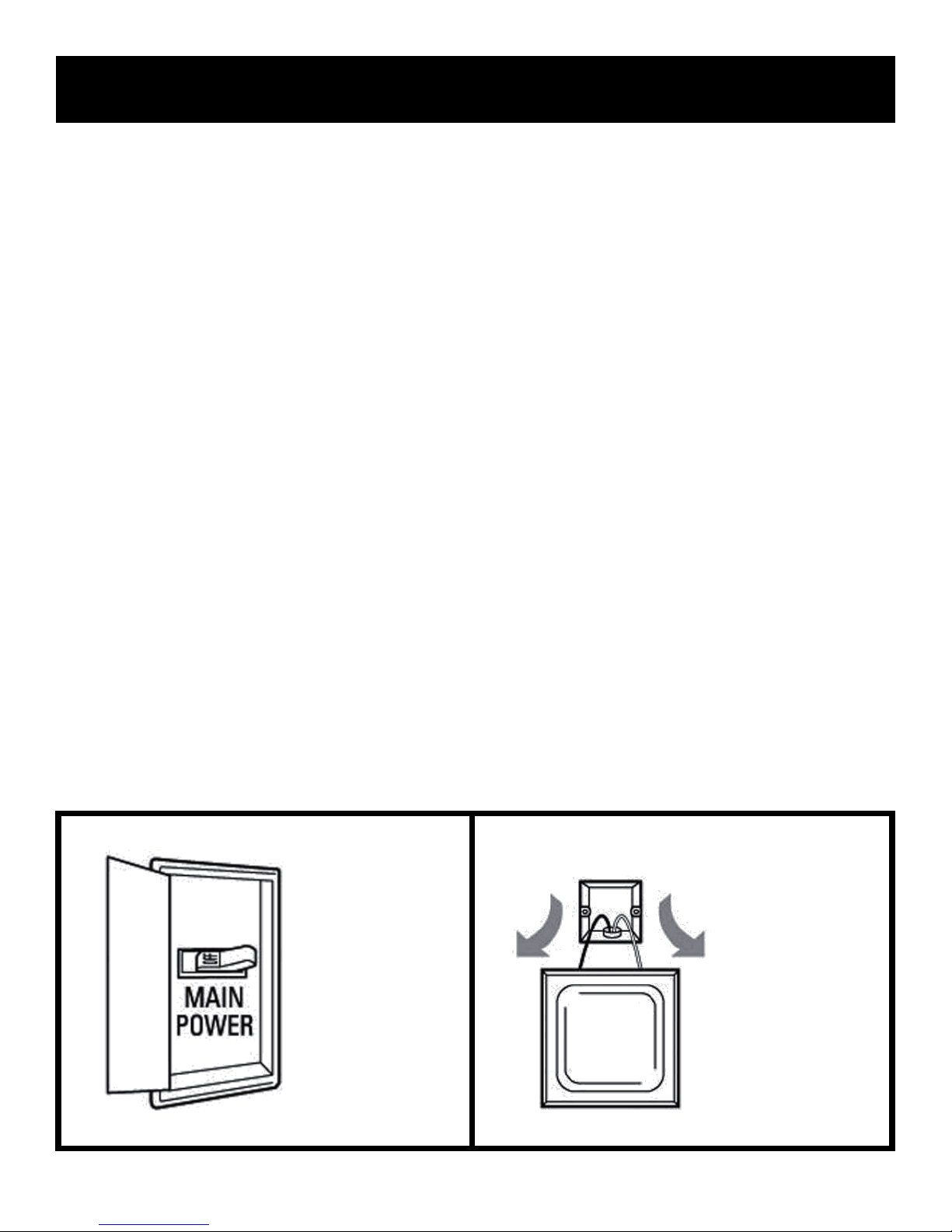
Shut off main
power at the
circuit breaker
or fuse panel
before removing
old fixture.
Remove
old fixture.
Disconnect wire.
3
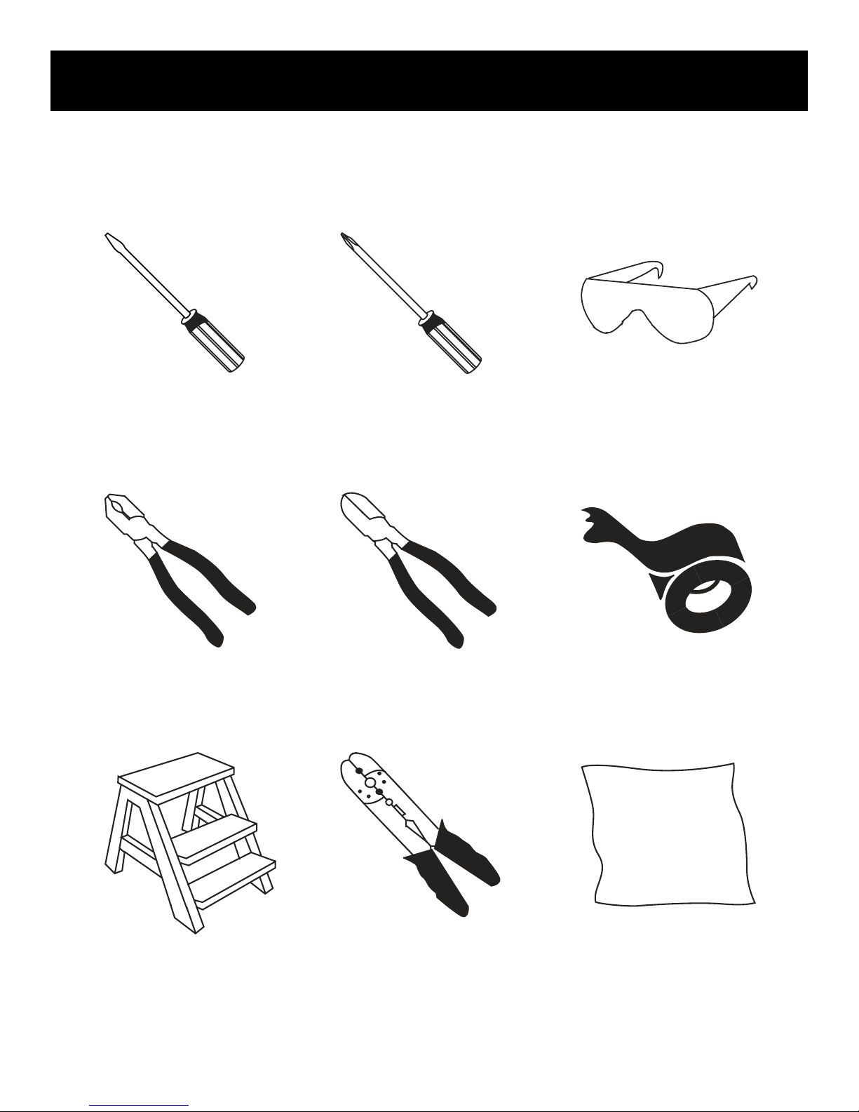
REQUIRED
To begin / tools needed (not supplied)
Flathead
Screwdriver
Pliers
Phillips
Screwdriver
Wire Cutters
Safety Glasses
Electrical Tape
Step Ladder
Wire Strippers
Soft Cloth
4
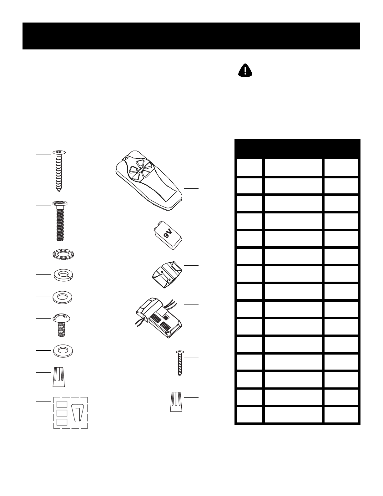
Hardware included
Carefully unpack and identify each part to make sure you
have everything ready for installation. Lay out each part on
a clean flat area such as a table or floor. Check to make sure
you have the following:
Hardware Bag Remote Control
A
J
B
K
ATTENTION: parts are not to scale.
PART DESCRIPTION
A 2
B 2
C 2
D 2
E 2
Wood Screw (Long)
Mounting Screw
Star Washer
Spring Washer
Flat Washer
QUANTITY
C
D
E
F
G
H
F
Blade Screw
15+1
L
G
H 4
M
I 1
J 1
K 1
N
L 1
M 1
I
O
N 2
O 6
Fibre Washer
Plastic Wire Nut
Balance Kit
Transmitter
9 Volt Battery
Transmitter Holder
Receiver
Wood Screw (Short)
Plastic Wire Nut
15+1
5
 Loading...