

Page 1
GE Energy
TRANSPORT X
Portable Dissolved Gas Analysis
Users Guide
40-0157-04
2011 Kelman Ltd. All Rights Reserved
Page 2

TRANSPORT X Users Guide
TRANSPORT X
Users Guide
Contents ........................................................................................................................ 2
(EN) Safety Warnings .................................................................................................. 3
(FR) Consignes de sécurité ......................................................................................... 4
1. Introduction ........................................................................................................ 5
2. Technical Specifications................................................................................... 5
3. System Description ........................................................................................... 5
3.1 TRANSPORT X ................................................................................................................................... 5
3.2 Sample Bottle and Connectors ................................................................................................. 6
3.3 Accessories Kit .................................................................................................................................. 8
3.4 Thermal Printer ................................................................................................................................. 8
4. Operation ............................................................................................................ 9
4.1 Turning On/Off ................................................................................................................................ 10
4.2 Preventing Contamination ........................................................................................................ 11
4.3 TRANSPORT X Operation ........................................................................................................... 11
5. Taking an Oil Sample ..................................................................................... 42
6. Cleaning the Apparatus ................................................................................ 44
6.1 Cleaning the Syringe, Valves and Lid Assembly .............................................................. 44
6.2 Cleaning the Syringe .................................................................................................................... 44
6.3 Cleaning the Bottle and Lid Assembly ................................................................................. 45
7. Sampling and Analyzing Gases from Gas-Collecting (Buchholz) Relays45
7.1 Gas Sampling .................................................................................................................................. 45
7.2 Gas Sample Injection and Analysis ....................................................................................... 47
8. System Check .................................................................................................. 49
8.1 System Gas Check Procedure ................................................................................................. 49
8.2 Hydrogen .......................................................................................................................................... 55
9. Troubleshooting ............................................................................................. 55
10. Logfile Extraction ........................................................................................... 62
10.1 System Requirements ................................................................................................................. 62
10.2 Installation Instructions .............................................................................................................. 62
10.3 Logfile Retrieval .............................................................................................................................. 62
10.4 File Structure ................................................................................................................................... 62
11. Exchanging a Bottle Lid Assembly .............................................................. 62
Appendix 1: Operating Environment for DGA Equipment ................................ 65
Appendix 2: Installing the TRANSPORT X Driver in Windows 7 or Vista ......... 66
Appendix 3: Importing TRANSPORT X Results Into PERCEPTION ..................... 73
Appendix 4: Glossary ............................................................................................... 76
All rights Reserved. Kelman Ltd.
This release of this document is accurate at the time of this writing. Kelman Ltd. reserves the
right to change the TRANSPORT X and this document without notice.
Kelman Ltd, Lissue Industrial Estate East
Lissue Road, Lisburn, BT28 2RE, United Kingdom
Tel: +44 28 9262 2915; Fax: +44 28 9262 2202
e-mail: transportx@ge.com
Page 3
TRANSPORT X Users Guide
Web: www.gedigitalenergy.com
(EN) Safety Warnings
MODE OF OPERATION OF TRANSPORT X
If the TRANSPORT X is used in a manner not specified by the manufacturer, the protection provided
by the TRANSPORT X may be impaired.
DISCONNECTION FROM POWER SUPPLY
Disconnection from the supply is achieved through the power inlet connector. To disconnect from
the supply, turn off the device using the touch screen, then power off using the ON/OFF switch, then
disconnect the supply cord.
EXHAUSTED GASES
Gases exhausted by the TRANSPORT X are at concentrations that are non-flammable and non-toxic.
All exhausted gases are quickly diluted into the surrounding atmosphere.
BATTERY REPLACEMENT AND DISPOSAL
The TRANSPORT X uses a lithium coin cell battery. The lithium coin cell battery is a long-life
battery and may never need to be replaced. If battery replacement is necessary it should be
performed by an authorized service technician.
CAUTION: There is a danger of a new battery exploding if it is incorrectly installed. Replace
the battery only with the same or equivalent type recommended by the manufacturer. Do
not dispose of the battery in a fire or with household waste. Contact your local waste
disposal agency for the address of the nearest battery deposit site.
WASTE ELECTRICAL AND ELECTRONIC EQUIPMENT WEEE DIRECTIVE
In the European Union, this label indicates that this product should not be disposed of with
household waste. It should be deposited at an appropriate facility to enable recovery and
recycling. GE recommends that you follow local WEEE requirements or alternatively contact
ge4service@ge.com for further information on returning your product.
This product has been tested to the requirements of CAN/CSA-C22.2 No. 61010-1, second
edition, including amendment 1, or a later version of the same standard incorporating the
same level of testing requirements.
Warnings:
There are no serviceable parts inside the TRANSPORT X.
For continued fire protection, use only an approved and recommended fuse.
Do not use the TRANSPORT X if the power cord is visibly damaged or worn out or missing, or
if the PE pin is damaged.
Use only a safety-approved power cord.
Do not operate the TRANSPORT X (top cover open) in rain conditions.
The TRANSPORT X should be stored with the lid closed when not in use to avoid accidental
damage during transit.
The TRANSPORT X should not be left operating unsupervised.
Page 4
TRANSPORT X Users Guide
(FR) Consignes de sécurité
MODE DE FONCTIONNEMENT DU TRANSPORT X
La garantie commerciale pourra être annulée si la défectuosité est causée par une utilisation non
conforme, une négligence ou une modification non autorisée du TRANSPORT X.
MISE HORS TENSION
La mise hors tension est réalisée par le connecteur d’admission de puissance. Pour déconnecter le
TRANSPORT X, arrêter le dispositif en utilisant l’écran tactile, puis mettre hors tension en utilisant le
commutateur « MARCHE/ARRÊT », ensuite débrancher le cordon d’alimentation de la prise secteur.
GAZ D’ÉCHAPPEMENT
Les gaz produits par le TRANSPORT X sont à des concentrations qui sont non inflammables et non
toxiques. Tous les gaz d’échappement sont rapidement dilués dans l’atmosphère environnante.
REMPLACEMENT ET RECYCLAGE DE LA BATTERIE
Le TRANSPORT X utilise une batterie bouton au lithium, qui est une batterie de longue vie et
peut ne jamais devoir être remplacée. Si le remplacement de la batterie est nécessaire, il
devra être exécuté par un technicien autorisé.
ATTENTION: Il y a un risque d’explosion si la nouvelle batterie n’est pas installée correctement.
Remplacez la batterie uniquement par le modèle recommandé par le fabricant. Ne pas
éliminer cette batterie dans un feu ou avec des déchets municipaux. Contactez votre agence
locale de recyclage pour connaître l’emplacement le plus proche.
DIRECTIVE SUR LA COLLECTE DES DÉCHETS DES ÉQUIPEMENTS ÉLECTRIQUES ET ÉLECTRONIQUES
A l’intérieur de la Communauté Européenne, cette étiquette indique que ce produit ne doit
pas être jeté avec les ordures ménagères. Il doit être déposé dans un centre de traitement
qui permet le recyclage.GE vous conseille d’utiliser les méthodes et directives WEEE locales
ou sinon de contacter ge4service@ge.com pour plus d’information sur comment renvoyer
votre produit
Ce produit a été testé aux exigences de la CAN/CSAC22.2 No 610101, deuxième édition, y
compris l’amendement 1, ou une version ultérieure de la même norme comportant le même
niveau d’exigences relatives aux essais.
Consignes de sécurité:
Aucune pièce à l’intérieur du TRANSPORT X n’est réparable par l’utilisateur.
Utiliser uniquement le modèle de fusible approuvé et recommandé.
Ne pas utiliser le TRANSPORT X si le cordon d’alimentation de secteur est endommagé, usé ou
manquant.
Utiliser uniquement un cordon d’alimentation sécuritaire et approuvé.
Ne pas utiliser le TRANSPORT X (couvercle supérieur ouvert) par temps de pluie.
Le TRANSPORT X doit être entreposé avec le couvercle fermé afin d’éviter tout dommage
accidentel durant le transport.
Le TRANSPORT X ne doit pas être laissé sans surveillance durant son fonctionnement.
TRANSPORT X Users Guide Page 4 Ver. 40-0157-04 03/07/2013
Page 5

TRANSPORT X Users Guide
FAULT GAS
CALIBRATED RANGE (ppm)
Hydrogen (H2)
5 – 5,000
Carbon dioxide (CO2)
2 – 50,000
Carbon monoxide (CO)
1 – 50,000
Methane (CH4)
1 – 50,000
Ethane (C2H6)
1 – 50,000
Ethylene (C2H4)
1 – 50,000
Acetylene (C2H2)
0.5 – 50,000
Water (H2O)
0 – 100 % relative saturation
PARAMETER
VALUE/MEETS
Accuracy
Gas: ± 5 % or ± 2 ppm (whichever is greater) *
Water: ± 3 ppm
Power supply
115/230 Vac, 50/60 Hz, 40 W
Fuse
F6.3 AH, 250 V, 5 x 20 mm
Battery
Maxell CR2032 lithium coin cell, 3 V
Digital output
USB
Hardcopy output
2-inch thermal printer
Operating temperature
0 – 50 °C (32 – 122 °F)
Operating altitude
Maximum 2,000 m
Operating pressure
760 – 1040 millibar
Weight
11 kg (24 lbs), excluding accessories case
Dimensions
440 x 340 x 220 mm
IP Rating
IP20 (operating)
1. INTRODUCTION
Accurate knowledge of the condition of oil-filled equipment is of paramount importance to electrical
utilities. Dissolved Gas Analysis (DGA) has been essential in this area for many years, allowing faults
to be detected in their early stages, costly outages to be avoided and assets to be optimized.
The TRANSPORT X represents a new generation of test equipment for DGA in equipment oil, allowing
accurate, rapid, reliable results in the field. To ensure optimum performance of the TRANSPORT X it is
important to read this manual fully before using the equipment.
2. TECHNICAL SPECIFICATIONS
Table 1. Technical Specifications
* Accuracy is defined as accuracy of the gas analysis system and does not purport to define
gas-in-oil measurement accuracy which is affected by sampling and/or oil type.
3. SYSTEM DESCRIPTION
3.1 TRANSPORT X
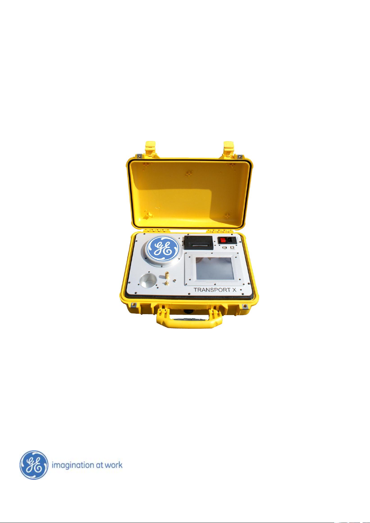
The TRANSPORT X (see Figure 1) utilizes photo-acoustic spectroscopy (PAS) to perform extremely
high quality DGA analyses, giving measurements of all the fault gases plus moisture.
The gases extracted from the oil sample using a highly stable headspace equilibrium extraction
method are then measured using infrared photo-acoustic spectroscopy (a semiconductor sensor for
hydrogen). The TRANSPORT X can also test gas samples taken from a Buchholz relay (although with
reduced accuracy due to a very large dilution factor). The wide dynamic range of measurement of
the TRANSPORT X means it is also very suitable for testing tap-changer and circuit breaker oil.
The TRANSPORT X is contained within a rugged, impact-resistant, carrying case. Accessories for DGA
tests of oil are contained within a separate lightweight case. These include a sample bottle with
connections and pipes, and a syringe for extracting a 50-mL oil sample from the equipment and
injecting it directly into the bottle (see Section 3.2).
The TRANSPORT X contains an embedded PC and touch screen. The incorporated software contains
instructions to guide the user through the operation of the system and algorithms to assist the
TRANSPORT X Users Guide Page 5 Ver. 40-0157-04 03/07/2013
Page 6
TRANSPORT X Users Guide
diagnosis of the electrical equipment. The PC has an internal database that can store over
16,000 records. Communication with external PC’s is possible via USB connections, allowing
databases to be downloaded to a laptop or desktop PC and then shared as required.
Figure 1. TRANSPORT X
A 2-inch thermal printer is provided, enabling the user to maintain hard copy records of all samples
tested on the instrument.
The power supply requirements are 115/230 Vac, 50/60 Hz.
A System Check Kit is available to allow the user to check the calibration accuracy of the
TRANSPORT X (see Section 8).
Optional extras are available for sampling of direct gas samples (see Section 7), and also for the
forced cooling of oil samples.
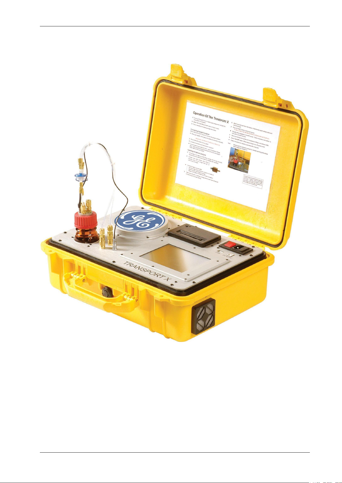
3.2 SAMPLE BOTTLE AND CONNECTORS
The sample bottle provided includes a “lid assembly” (see Figure 2) that incorporates airtight
compression fittings and a temperature probe incorporating a capacitance moisture sensor, all of
TRANSPORT X Users Guide Page 6 Ver. 40-0157-04 03/07/2013
Page 7
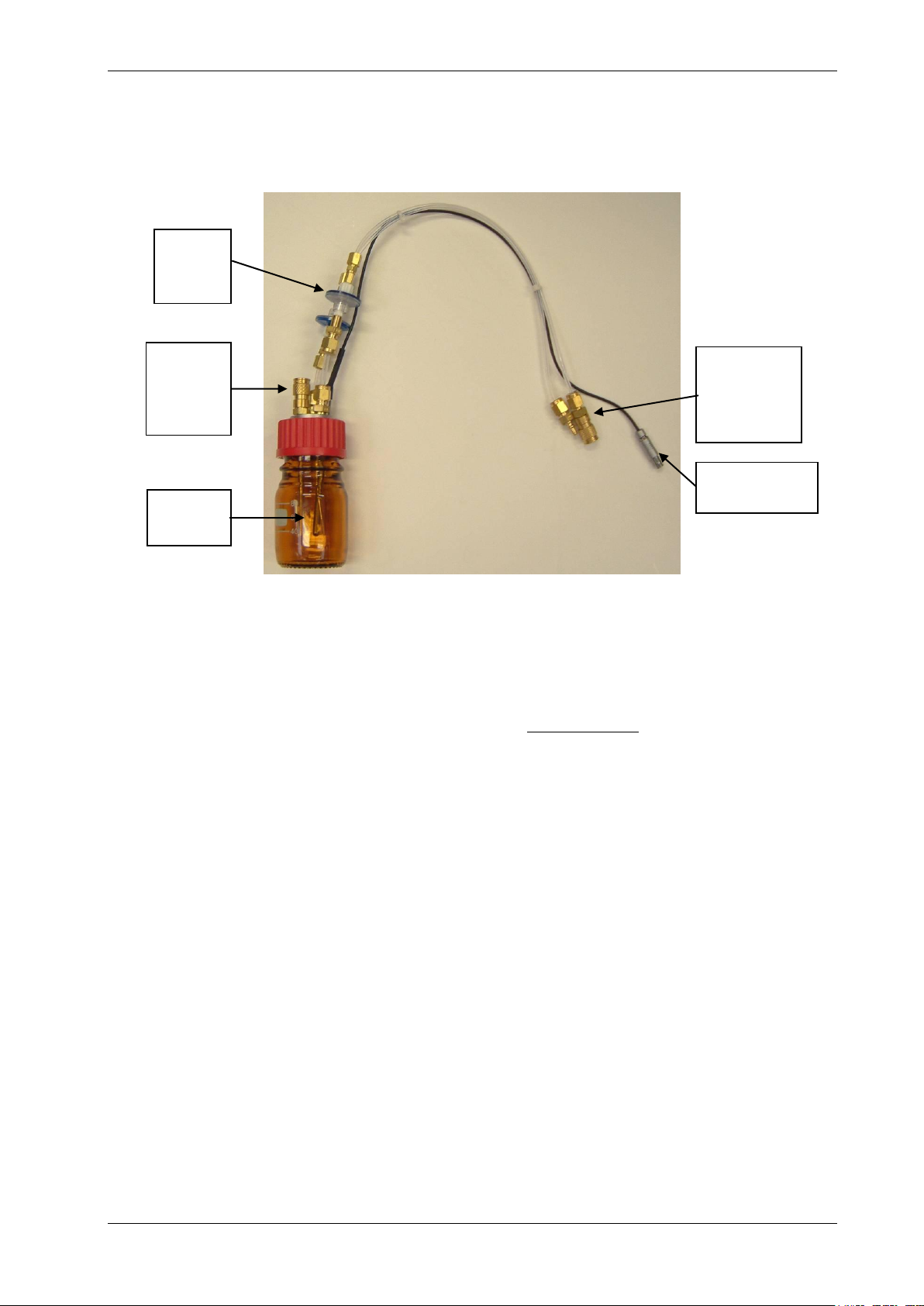
TRANSPORT X Users Guide
Sample
Bottle
Airtight
gas inlet
and outlet
fittings
Airtight
sample
injection
valve
Temperature
probe
In-line
Teflon
filters
which are to be connected to the top panel of the TRANSPORT X. These gas connectors are of the
simple “snap-in” type but they are “polarized” so that only one order of connection of the input and
return is possible. Users must ensure that these connections are fully made when using the
TRANSPORT X.
Figure 2. Sample Bottle and Lid Assembly
It is recommended to analyze the sample as soon as possible after extraction, so that minimal
degradation of the oil sample occurs. However, GE Energy provides a ground glass syringe with the
TRANSPORT X that can be used for reliable sample storage for several days, provided it is kept out of
direct sunlight and extremes of temperature.
It is essential that the sample bottle be kept upright and not be inverted or placed in storage on its
side while containing oil to avoid ingress of oil into the pipe work. Dispose of the oil as soon as the
sample has been tested to minimize the risk of accidental pipe contamination (see Section 6).
Clean the bottle thoroughly after each test with a clean dry cloth or tissue (see Section 6).
It is important to ensure there is no residue of oil left in the oil injection port of the lid assembly or the
connections valve of the syringe, as this could cause contamination of the next sample to be tested.
Expel any oil trapped in these locations using a syringe filled with normal ambient air. This will ensure
that no unwanted residue of oil remains from a previous sample.
Care should also be taken to prevent any contamination from the syringe and thorough cleaning
should be performed after each analysis (see Sections 5 and 6).
Two Teflon-coated magnetic stirrers are provided; place one in the bottle before the lid is screwed on
during assembly of the pipe work. This magnet is rotated within the bottle during the analysis cycle,
and its presence is essential for the accurate operation of the TRANSPORT X. The magnetic stir bar
should also be wiped clean after each test. The stir bar can be removed from the oil in the bottle
using the retriever stick provided.
An in-line Teflon filter is fitted in both the return and inlet gas pipes. Luer lock fittings are used to
connect these filters. These fittings allow for quick replacement of the filters at regular intervals or if
oil should get into the pipe work by accident, thus blocking the filters. These filters are impervious to
oil at operating pressure and function to protect the instrument from oil aerosol, accidental spills and
airborne dust. Both these filters must be present at all times; if a spill occurs and oil makes its way
into the gas analysis chamber of the photo-acoustic module, the instrument will require a new
spectrometer.
It is recommended that the Teflon filters be changed after every 20 samples and the user will be
reminded to do this by the TRANSPORT X. If any oil residue is present in the pipes, or the filters
TRANSPORT X Users Guide Page 7 Ver. 40-0157-04 03/07/2013
Page 8

TRANSPORT X Users Guide
50-mL
syringe
Sample
Bottles
Bottle lid
assembly
Teflon
filters
115/230 V
power
cable
Quick
connection
valve
Magnet
retriever
Tefloncoated
magnets
3-way
plastic
stopcock
appear discolored, then the filters should be replaced before testing the next sample. Clean the pipes
by a compressed air blowout if oil is present in the pipes.
3.3 ACCESSORIES KIT
The TRANSPORT X comes complete with a full range of accessories and some replacement spare
parts. These include:
1 x 50-mL ground glass syringe
1 x three-way plastic stopcock (for use with syringe)
1 x bottle lid assembly
1 x magnet retriever
1 x quick connection valve (for oil injection from the syringe)
2 x Teflon coated stir bars
12 x replacement Teflon filters
1 x 115/230 V power cable
3 x sample bottles
All of the accessories are supplied in a light carry case (see Figure 3), with protective foam inserts.
Figure 3. Accessories Kit
3.4 THERMAL PRINTER
The TRANSPORT X is equipped with an in-built 2-inch thermal printer that can provide hard copies of
results on-site. Changing the paper roll is very simple. Release the paper holder cover by depressing
the black catch on the left hand side of the holder (see Figure 4). To gain access to the paper roll
holder, lift the holder cover by its left hand edge, and swivel it on its right hand edge.
Place the new roll of paper over the roll holder and then lock back the paper holder cover in its
original position. The button on the top left corner allows the user to feed the paper through the
printer when fitting a new roll of paper, and also to check the function of the printer. Care must be
taken to ensure the thermo-sensitive side of the paper is orientated correctly during installation.
TRANSPORT X Users Guide Page 8 Ver. 40-0157-04 03/07/2013
Page 9

TRANSPORT X Users Guide
PC sync
port
Note: If the printouts from the thermal printer begin to show a red tint, it is an indication that a new roll of paper will be
needed soon.
Figure 4. Thermal Printer With Release Catch on the Left Hand Side
4. OPERATION
The TRANSPORT X has been designed to provide the user with a reliable device that is easy to use in
the field. The embedded PC and touch-screen display step-by-step user instructions, and there is also
an Instruction Card inserted in the lid of the case. A syringe and valves are supplied for oil sampling
and injection.
Note: Please read carefully and observe the following instructions.
Read and follow the on-screen instructions carefully.
Always use 50-mL samples of oil.
Always use a clean syringe, lid assembly and bottle (see Sections 4.2 and 6).
DO NOT use solvents to clean any of the apparatus or accessories.
Place one magnetic stirrer piece in the bottle for the sample to be analyzed correctly.
Following oil injection the sample bottle must not be moved until the analysis is complete. If the
bottle is moved the results will be adversely affected.
When containing oil the sample bottle must be kept upright to avoid ingress of oil into the pipe
work of the lid assembly.
Always ensure the pipes’ quick connect fittings are connected correctly and securely, as per
instructions.
When removed, the bottle lid assembly should be held upright then cleaned carefully with a cloth
or tissue after use and before storage to avoid any ingress of oil into the pipe work (see
Section 6).
Always empty the sample bottle waste oil after a test is completed. Also, clean the apparatus
after every test (see Section 6).
The Purge time can be increased (maximum 10 minutes) to help prevent carry-over from a
heavily gassed sample to the next sample. 10 minutes should be used where available time
permits.
Once the TRANSPORT X is unpacked from new, or after storage, the user should run a System
Flush operation to help clear the gas paths from potential contamination from any packing
material/gas effluents (see Section 4.2).
TRANSPORT X Users Guide Page 9 Ver. 40-0157-04 03/07/2013
Page 10
TRANSPORT X Users Guide
4.1 TURNING ON/OFF
Where possible the instrument should be powered up 20 minutes prior to the first sample injection to
allow it to heat up. Oil sampling can be performed in this time if desired. The instrument can also
undergo a system flush during this period if desired.
The TRANSPORT X is powered by mains-supplied electricity or a suitable AC supply from a DC
inverter. To connect the unit to the mains supply, use the IEC cable supplied with the unit. With the
unit connected to the mains, switch the power On using the red power switch at the top right of the
front panel. The touch screen will then show the launch of the TRANSPORT X software (there will be
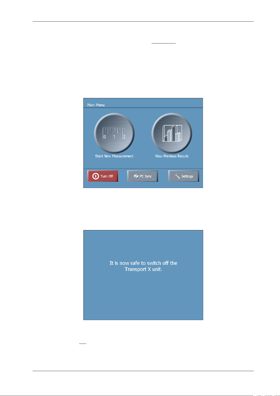
up to 20 seconds during which the software will boot) and the Main Menu screen (see Figure 5) will
be displayed.
Figure 5. Main Menu Screen
To turn the unit Off, press the Turn Off button found at the bottom left of the Main Menu (see
Figure 5). The system will then advise when it is ready to be switched off (see Figure 6). Use the red
power switch to switch off the mains supply.
Figure 6. “Safe to Switch off Power Supply” Screen
Similar to a PC, it is not recommended to turn off the unit directly from the power switch without
following the above shutdown procedure.
TRANSPORT X Users Guide Page 10 Ver. 40-0157-04 03/07/2013
Page 11
TRANSPORT X Users Guide
4.2 PREVENTING CONTAMINATION
The TRANSPORT X is designed to prevent contamination between samples using only simple
cleaning techniques for the syringe, jar and lid assembly (see Section 6).
For best results:
Clean the syringe thoroughly between each sample with a cloth or tissue (see Section 6).
Clean the bottle and stirrer with a cloth or tissue.
Clean the lid assembly pipes and probes with a cloth or tissue.
It is recommended that after first unpacking the unit and whenever time permits, the user should
implement a System Flush. This process flushes ambient air through the TRANSPORT X for
20 minutes, and will help clear any potential contamination from packing material/prior samples.
This function can also be used to clear the TRANSPORT X of gas after a concentrated gas-in-oil
sample e.g. LTC. Details regarding the use of this function are given at Section 4.3.5.2.
4.3 TRANSPORT X OPERATION
The instructions displayed on the touch screen are used to control the operation of the
TRANSPORT X. Upon powering-up the screen shows the Main Menu display (see Figure 5).
There are five options:
Start New Measurement: see Section 4.3.1.
View Previous Results: see Section 4.3.4.
Turn Off: see Section 4.1.
PC Sync: communicating with PC software – see manual.
Settings: see Section 4.3.5.
4.3.1 Performing a New Measurement
4.3.1.1 Entering Measurement Details Into the Database
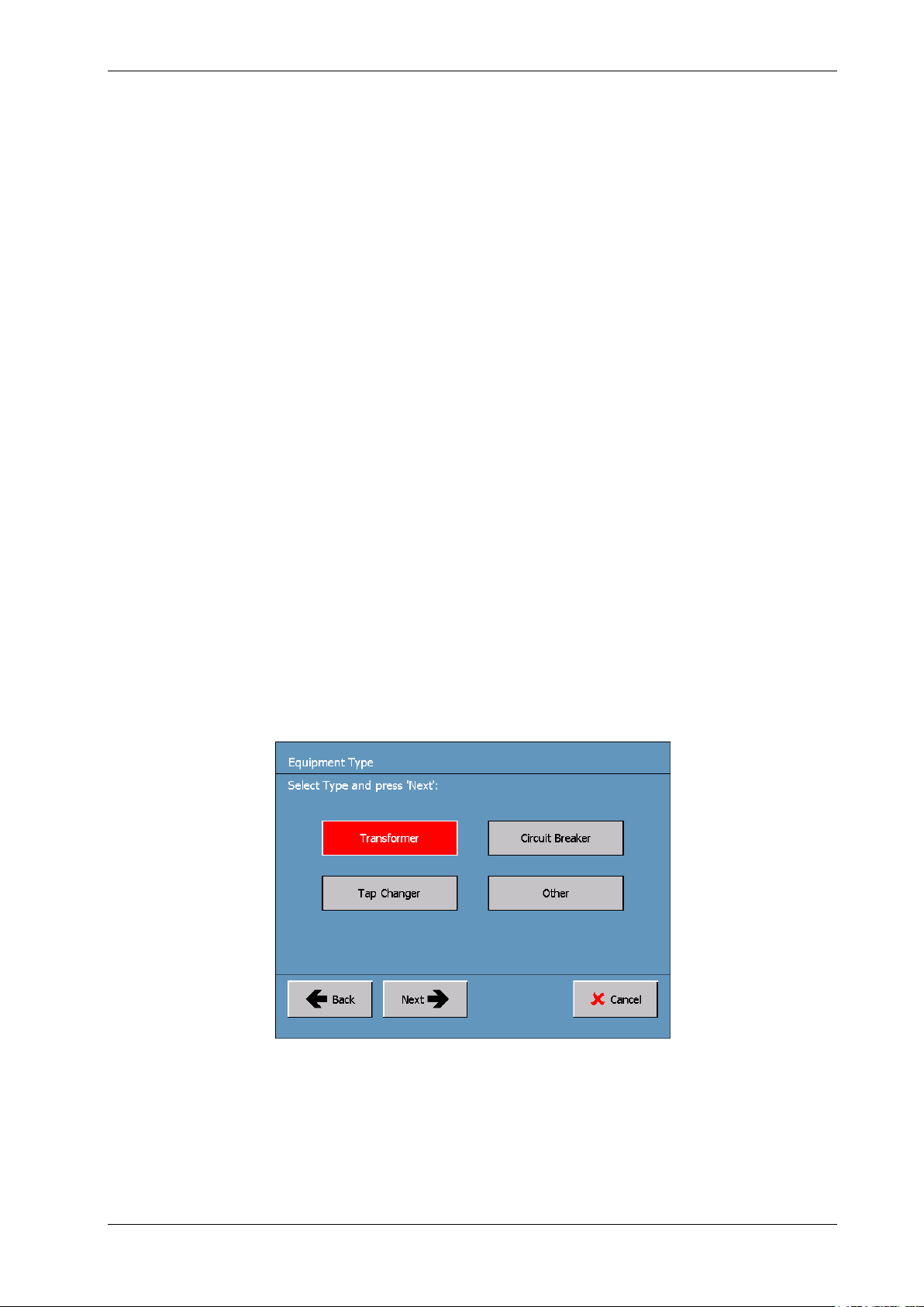
After selecting Start New Measurement in the Main Menu screen (Figure 5), the user must select the
Equipment Type to be analyzed from the options available (see Figure 7). This selection is important
for the database and the diagnosis options for the sample.
Figure 7. Equipment Type Screen
Highlight the desired option and then press the Next button (the default selection is displayed in red).
The TRANSPORT X now requests that the information for the database relating to the Equipment
Location and the Equipment Identification (ID) is entered into the unit’s memory. The information
required by these two screens is vital as it forms the store and search criteria for all records. If the
information is new (i.e. not already stored in the Transport X memory), the unit will use the new
information and store it as a new set of records with the appropriate date stamp.
TRANSPORT X Users Guide Page 11 Ver. 40-0157-04 03/07/2013
Page 12
TRANSPORT X Users Guide
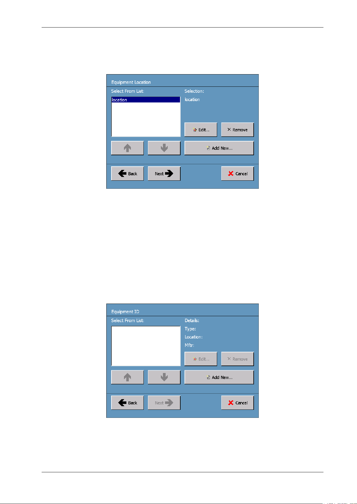
First, the Equipment Location screen is displayed (see Figure 8). If the equipment location already
exists in the database from a previous test, then the user can select this from the existing database
list displayed on the screen using the Up and Down arrows. Once the correct location is highlighted
in the left hand window, press the Next button to move to the Equipment ID screen, which is the next
screen in the information/data input process.
Figure 8. Equipment Location Screen
If the correct location information does not already exist in the database, then the user has to enter
it. To do this the user must first press the Add New… button found in the Equipment Location screen
(Figure 8). This action causes the display of the keypad on the touch screen (similar to Figure 10).
Enter the Equipment Location details using the keypad.
The information stored in the database relating to Equipment Location can also be edited using the
Edit… button located in the middle of the screen – highlight the record to be edited using the Up and
Down arrows, then press the Edit… button and again the Keypad screen is displayed (similar to
Figure 10) to enable the user to edit an existing database record.
Once the Equipment Location details are correctly entered into the database, press the OK button
(which is now active) at the bottom of the Keypad screen. The Equipment ID screen is then displayed
(see Figure 9).
Figure 9. Equipment ID Screen
Select from the displayed list the appropriate Equipment Identification details of the equipment that
is to be used for the analysis then press the Next button. As in the case for the Equipment Location
screen, existing details of a record of the Equipment ID screen can be edited by pressing the Edit…
TRANSPORT X Users Guide Page 12 Ver. 40-0157-04 03/07/2013
Page 13
TRANSPORT X Users Guide
button. However, if the database contains no information concerning the equipment about to be
tested, it will be necessary to add this information to the database for the first time.
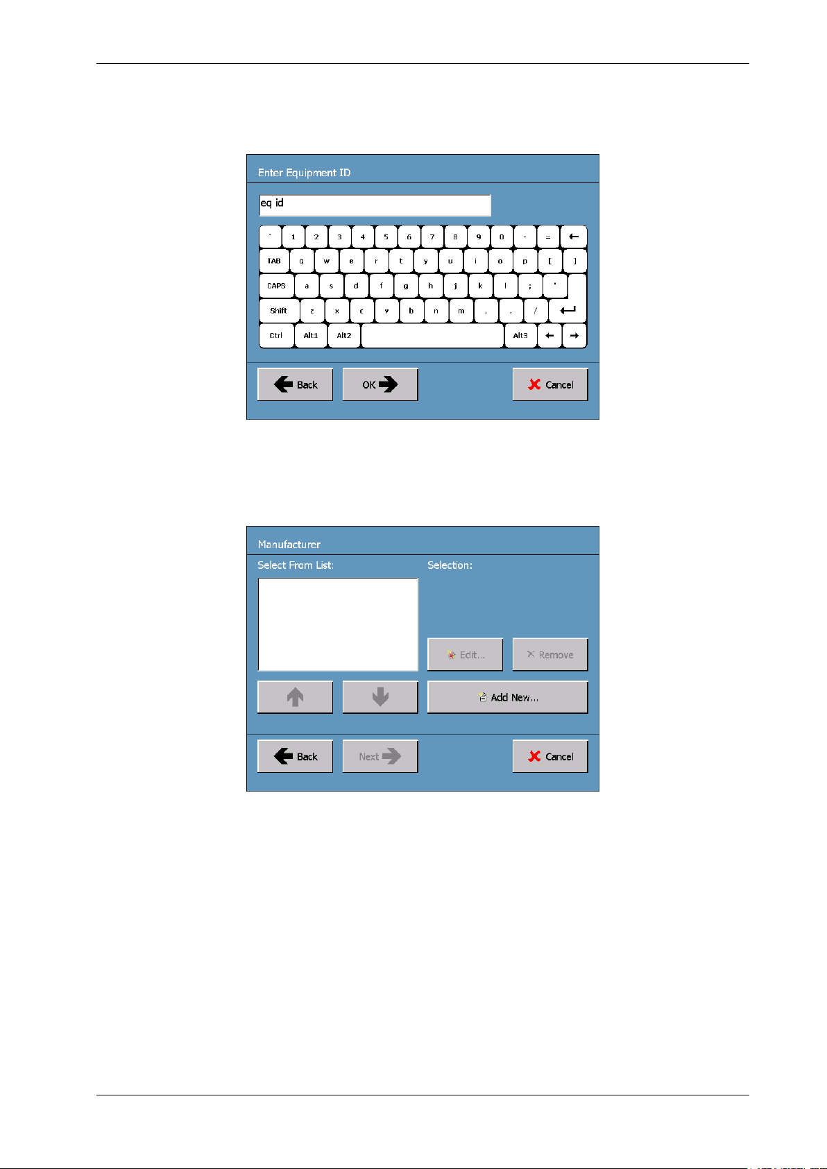
To add new Equipment Identification information, press the Add New… button. The keypad for
entering Equipment Identification details is then displayed on the screen (see Figure 10).
Figure 10. Keypad for Entering Equipment ID Details
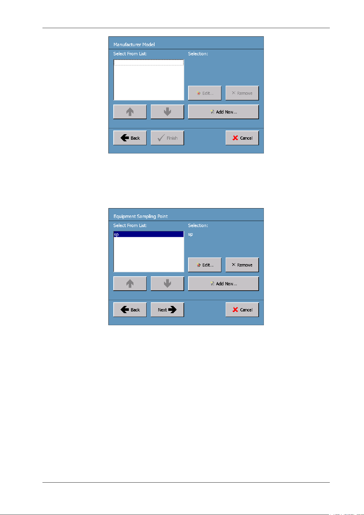
Add the new Equipment ID details and then press the now active OK button. The Manufacturer
screen is then displayed (see Figure 11).
Figure 11. Manufacturer Screen
Using the Up and Down arrows, select the appropriate Equipment Manufacturer from the entries in
the displayed list, then press the Next button. Alternatively, to add a new manufacturer to the list,
press the Add New… button; the keypad is displayed (similar to Figure 10). Enter the new
Manufacturer details into the database, press the OK button at the bottom of the keypad and the
Manufacturer Model screen is displayed (see Figure 12).
As for the Manufacturer screen, choose from the displayed list the appropriate model of the
equipment about to be analyzed, or press the Add New… button to add a new model to the
database. When the correct model details are either selected or entered into the database, press the
Finish button at the bottom of the Manufacturer Model screen or the OK button at the bottom of the
Keypad screen. The Equipment ID screen (Figure 9) is again displayed to allow for confirmation of all
the details entered up to this point.
TRANSPORT X Users Guide Page 13 Ver. 40-0157-04 03/07/2013
Page 14
TRANSPORT X Users Guide
Figure 12. Manufacturer Model Screen
When the Equipment ID details have been correctly entered into the database, press the OK button
at the bottom of the keypad screen. This causes the display of the Equipment Sampling Point screen
(see Figure 13).
Figure 13. Equipment Sampling Point Screen
The Equipment Sampling Point details are entered into the software following the same procedure as
discussed above for Equipment Location and Equipment ID. Typical sampling points may be Top,
Bottom, Cooling loop, etc. Once the Equipment Sampling Point details have been correctly entered in
the database, the user is required to provide details of the source of the sample that is about to be
used for a new measurement. To enter the Sample Source details, select the source from the two
options displayed on the Sample Source screen (see Figure 14).
The default is Oil Sample, but if the sample is gas from the Buchholz relay, then select Gas Sample.
Details regarding the sampling and analysis of gases from gas-collecting (Buchholz) relays are
described in Section 7. Press the Next button once the correct option has been selected.
TRANSPORT X Users Guide Page 14 Ver. 40-0157-04 03/07/2013
Page 15
TRANSPORT X Users Guide
Figure 14. Sample Source Screen
At this point, when all the necessary information has been entered into the database, a summary of
the New Measurement details is displayed in the Details screen (see Figure 15).
Figure 15. Details Screen
The user is required to check and confirm all the information that has been entered into the
database before continuing. If any errors are noted in the information displayed on the Details
screen, use the Back button to reverse back to the screen in the sequence of screens described
above where the incorrect entry has been made. Then correct the information entered into the
database at that point.
Pressing the Next button on the Details screen causes the display of the Optional Details screen
(see Figure 16). This screen provides the user with the option of adding comments to a Comment:
field for the sample data. This can be used to record additional information for a particular sample or
equipment. If this option is required, press the Set button found at the left of the Comment: field to
display the keyboard (similar to Figure 10) for entering comments. Press the OK button at the bottom
of the keyboard after typing in any comments.
The user also has the option of adding the Oil Sampling Temperature (in degrees Celsius), i.e. the
temperature of the oil at the time it was sampled as displayed by the transformer temperature
gauge or another temperature measurement option. This is used to calculate the % Relative
Saturation (%RS) of the sample. If the temperature is not added then the results will not include a
%RS figure. To enter the oil temperature, press the Set button found at the left of the Extraction
Temperature: field to display the keyboard (similar to Figure 10) for making the temperature entry.
Press the OK button at the bottom of the keyboard when the oil temperature has been entered.
TRANSPORT X Users Guide Page 15 Ver. 40-0157-04 03/07/2013
Page 16

TRANSPORT X Users Guide
Figure 16. Optional Details Screen
After all the sample information has been selected or entered, the software guides the user through
the testing process. Press the Next button to begin the testing process.
4.3.1.2 Readying the TRANSPORT X for Making a Test
While the user is entering the new Measurement Details into the database (Section 4.3.1.1), in the
background the TRANSPORT X is undertaking a process of system venting in preparation for taking a
new measurement.
Note: Venting occurs only upon the initial start-up of the TRANSPORT X.
Progress in performing the system venting is shown in the Venting System Progress screen (see
Figure 17), which will be observed if the first set of new Measurement Details are all entered before
the venting process has completed.
Figure 17. Venting System Progress Screen
It is a requirement that a clean dry bottle be used for each test. Figure 18 shows the initial instruction
screen for the testing process – the Install Bottle Instructions screen. Follow the on-screen
instructions and connect the sample bottle to the TRANSPORT X. Press the Next button to proceed
with the testing process.
TRANSPORT X Users Guide Page 16 Ver. 40-0157-04 03/07/2013
Page 17
TRANSPORT X Users Guide
Figure 18. Install Bottle Instructions Screen
If the temperature probe is not properly connected, the warning window shown in Figure 19 is
displayed. If this occurs, confirm correct connection of the temperature probe, then press the OK
button to proceed with the testing.
Figure 19. Bottle Installation Error Message
If the bottle temperature connection is in order, the Purging Time window (see Figure 20) is
displayed. The unit prepares for the oil sample by first “purging” with ambient air, and then by
automatically taking a zero reference measurement. The user selects the required Purging Time,
typically between 5 and 10 minutes. The default is 5 minutes, but longer purges can help eliminate
contamination from previous samples which were heavily gassed, for example from Tap Changer oil
samples.
TRANSPORT X Users Guide Page 17 Ver. 40-0157-04 03/07/2013
Page 18

TRANSPORT X Users Guide
Figure 20. Purging Time Window
Progress in purging the unit is shown in the Purging Progress screen (see Figure 21).
Note: If 5 minutes is selected, the actual time is approximately 5 minutes and 40 seconds as this is a default minimum.
If 6 minutes is selected, the actual time 6 minutes.
Figure 21. Purging Progress Screen
When the purging is completed, the unit automatically calculates the gas concentrations in the air of
the TRANSPORT X / dry sample bottle combination in order to provide a zero reference for sample
measurements using the selected sample bottle. The Progress screen is shown in Figure 22.
TRANSPORT X Users Guide Page 18 Ver. 40-0157-04 03/07/2013
Page 19

TRANSPORT X Users Guide
Figure 22. “Calculating the Gas Concentrations in Air” Progress Screen
Once the zero references have been calculated, the TRANSPORT X is ready for the oil sample to be
injected into the unit’s sample bottle.
4.3.1.3 Injecting Oil Samples Into the TRANSPORT X
Having obtained a representative oil sample (see Section 4), it is important that the sample be
handled correctly in order to ensure reliable results. Problems with sampling, storing or injecting the
oil sample can all affect eventual results.
Note: If a sample is not tested immediately after being taken, it is recommended to store it in a dark, cool place.
Follow the following procedural steps to inject the sampled oil into the TRANSPORT X sample bottle.
If the oil was hot when the sample was taken, shake the oil sample with a slight positive pressure on
the syringe plunger before submitting it to the TRANSPORT X for analysis. The reason for this advice
is that if the oil was hot when the sample was taken, it is possible for gas from the sample to come
out of solution and form a bubble as the oil cools. By shaking the sample with a slight positive
pressure on the syringe, the gas should be dissolved back into the oil and the sample should then be
ready for analysis.
Once the sample is confirmed to be correct, follow the on-screen instructions in the Gas Analysis
Instructions screen (see Figure 23) to inject the oil sample. These instructions are described in more
detail in the rest of this Section 4.3.1.3.
Figure 23. Gas Analysis Instructions Screen
TRANSPORT X Users Guide Page 19 Ver. 40-0157-04 03/07/2013
Page 20
TRANSPORT X Users Guide
Only 90 seconds are available to complete the injection process. The Gas Analysis Instructions
screen displays a progress bar representing the run-down of these 90 seconds and the Time
remaining for sample injection is displayed on the screen. The TRANSPORT X also emits a beep
sound at 5-second intervals during the injection period.
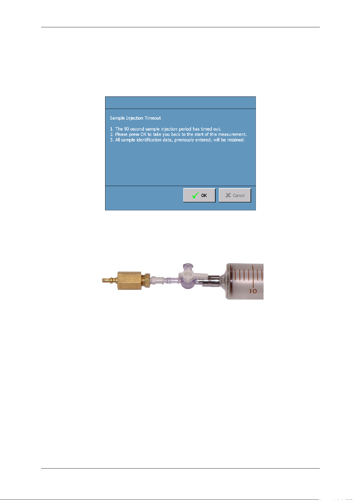
If the sample injection is not completed in the 90-second injection period that is available, the
Sample Injection Timeout screen is displayed (see Figure 24). The user is then required to press the
OK button and return to the start of the injection process.
Figure 24. Sample Injection Timeout Screen
Prior to sample injection, the male quick-connect fitting should be attached to the syringe’s
three-way stopcock (see Figure 25).
Figure 25. Male Section of the Quick-Release Valve Connected to the Syringe
Connect the syringe to the sample bottle. The outer sleeve of the female fitting on the lid assembly
should be held between the thumb and the forefinger and pressed downwards as far as it will go (see
Figure 26). Insert the male quick-connect fitting that is attached to the syringe firmly into the female
connector. A slight click is heard when the connection is fully made. Release the outer sleeve of the
female connector to secure the connection.
TRANSPORT X Users Guide Page 20 Ver. 40-0157-04 03/07/2013
Page 21
TRANSPORT X Users Guide
Figure 26. Outer Sleeve of the Female Connector
Turn the three-way valve 90 degrees to open the arm from the syringe to the bottle, thus closing the
side arm of the valve (see Figure 27).
Figure 27. Stopcock (Three-Way Valve) With Side Arm Closed
Note: If the side arm of the valve is not closed, the oil will escape.
Slowly depress the plunger of the syringe fully. When the syringe is fully depressed, maintain gentle
downward pressure on the plunger, wait 3-4 seconds and disconnect the syringe at the quickrelease valve. To do this, press down the sleeve of the female section and lift the syringe, three-way
valve and male quick-connect assembly away from the female section. Take care not to separate the
male quick-release section from the valve/syringe until the syringe is disconnected from the bottle at
the quick-release valve as that would provide an open channel for the gases to escape to
atmosphere.
Press the Next button on the Gas Analysis Instructions screen (Figure 23) to proceed with the
sample analysis.
4.3.1.4 Sample Analysis
Once the sample has been injected into the bottle, the temperature of the oil is measured. This is to
avoid condensation in the internal pipe-work of the system. Therefore it is recommended that “hot”
TRANSPORT X Users Guide Page 21 Ver. 40-0157-04 03/07/2013
Page 22
TRANSPORT X Users Guide
oil not be tested, and that it has time to cool. The important criterion is that the analysis cell is
warmer than the oil so it may be necessary to allow the unit to warm up if it has been stored in a cold
location prior to use. The temperature measurement takes 90 seconds.
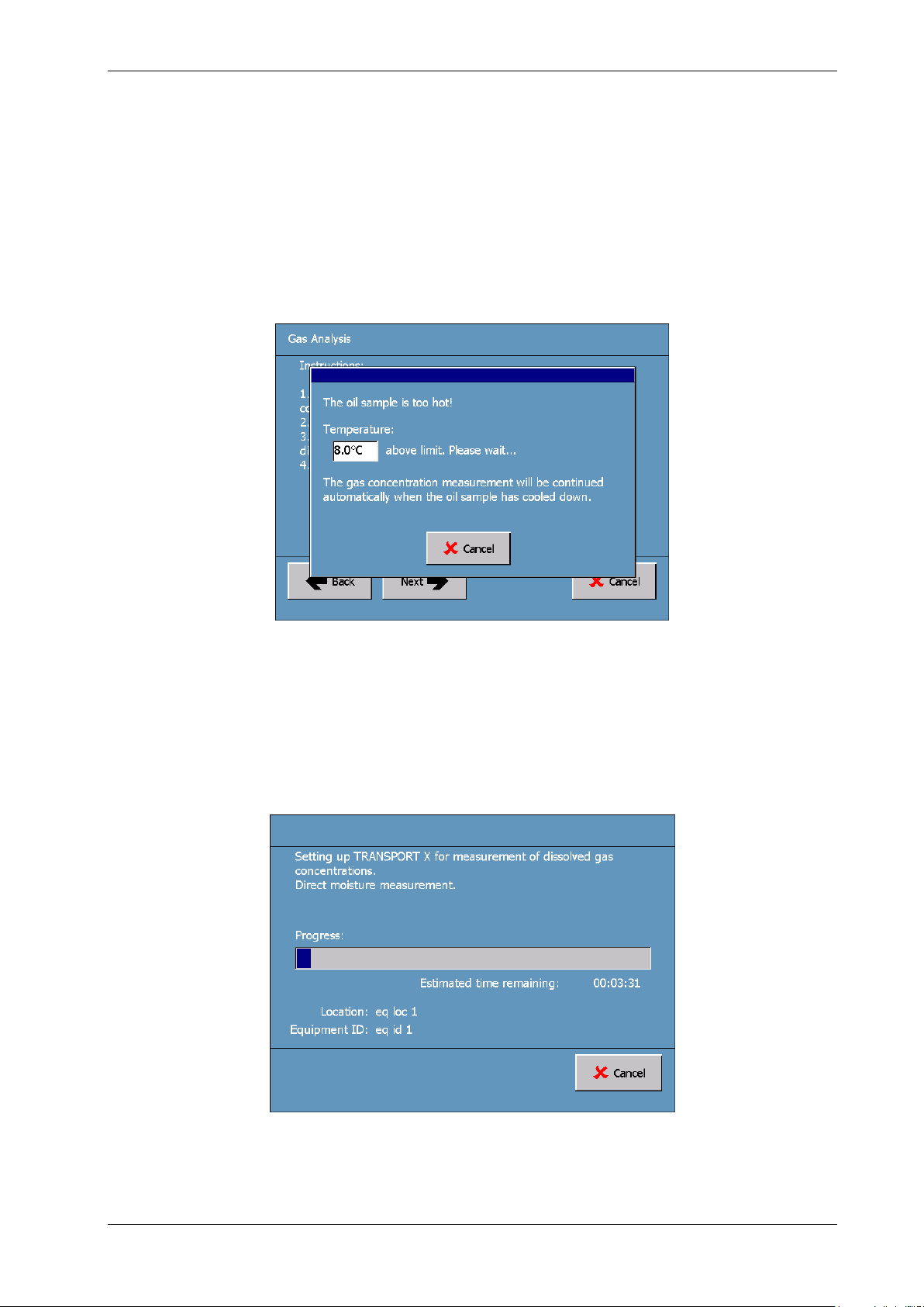
If the oil temperature is higher than the internal cell temperature, then the sample analysis will not
continue. The screen will display this temperature difference and its countdown (see Figure 28). Do
not remove the bottle from the bottle holder cavity during this period. When the temperature
difference figure reaches 0.0 °C, the unit will automatically start the analysis, possibly with a delay
while the unit resets. Ensure the bottle is in place in the holder when the unit commences the
analysis.
Note: If the bottle is not in place at this time, the magnetic stirrer will not operate and therefore the results will not be
correct.
Figure 28. Temperature Countdown Screen
After the oil temperature measurement has been taken, the unit begins the process of measuring the
dissolved gases in the oil sample. Progress in making the measurements is shown by the display, in
succession, of the Direct Moisture Measurement Progress screen (see Figure 29) and the
Measuring Dissolved Gas Concentrations Progress screen (see Figure 30). The measurements take
approximately 22 minutes to complete.
Note: Do not touch or remove the bottle from the holder during the measurement process.
Figure 29. Direct Moisture Measurement Progress Screen
TRANSPORT X Users Guide Page 22 Ver. 40-0157-04 03/07/2013
Page 23
TRANSPORT X Users Guide
Figure 30. Measuring Dissolved Gas Concentrations Progress Screen
When the measurement procedure is complete, the results of the measurement are shown on the
Results screen (see Figure 31). It shows the concentration levels of the various dissolved gases and
the Total Dissolved Combustible Gas (TDCG) level that have been measured in the sample oil. The %
Relative Saturation (% RS) of the sample is also displayed if the Sample Oil Extraction Temperature
was entered into the TRANSPORT X’s diagnostic software (Figure 16).
Figure 31. Results Screen (Oil Sampling Point)
Pressing the Next button displays the Results Options screen shown in Figure 32.
TRANSPORT X Users Guide Page 23 Ver. 40-0157-04 03/07/2013
Page 24

TRANSPORT X Users Guide
Figure 32. Results Options Screen
The Results Options screen makes available to the user a number of options for the next step:
Print Results: to activate the TRANSPORT X’s built-in thermal printer and produce a hardcopy
printout of the dissolved gas measurement results. When this button is pressed, the Printing
screen (see Figure 33) appears whilst the printing is in progress. An example of the type of
printout that is available is shown in Figure 34.
Figure 33. Printing Screen
Advanced…: to continue analysis of the measurement results using the TRANSPORT X’s
embedded DGA diagnostic tools (see Section 4.3.2).
Finish: to store the measurement results in the TRANSPORT X’s database.
Cancel: to abort the measurement results and delete it from the TRANSPORT X’s memory.
4.3.2 Analysis Tools
Note: The analysis tools incorporated into the TRANSPORT X do not represent the opinion of GE Energy; rather they are
based upon widely recognized standards and algorithms, with the various caution and warning alarm thresholds set
by the user.
By selecting Advanced… in the Results Options screen (Figure 32), the operator can use the
incorporated software tools to aid in the analysis of DGA results. This option is only available for
Transformer oil samples. If the user has entered Tap Changer, Circuit Breaker or Other in the
Equipment Type screen (Figure 7), then the analysis tools do not apply.
TRANSPORT X Users Guide Page 24 Ver. 40-0157-04 03/07/2013
Page 25

TRANSPORT X Users Guide
Figure 34. Results Printed by the TRANSPORT X’s Built-in Thermal Printer
4.3.2.1 DGA Analysis Using Caution and Warning Thresholds
The first diagnostic tool made available to the user after pressing the Advanced… button found in the
Results Options screen (Figure 32) is that which compares measured dissolved gas concentration
levels with the preset Caution and Warning levels for each gas that were previously entered into the
TRANSPORT X diagnostic software.
Note: Default gas concentration threshold levels have been pre-programmed into the TRANSPORT X diagnostic
software, but the thresholds are settable by the user, as described in this Section 4.3.2.1.
If the measured concentration value for any gas is above one of the threshold levels for that gas, an
appropriate warning is advised to the user. For example, if the DGA measurement for a particular gas
is above either the Caution or Warning threshold levels, that situation is highlighted in yellow (if above
the Caution level) or red (if above the Warning level) on the Analysis screen (see Figure 35). An overall
Transformer Condition of Normal, Caution or Warning can be provided based upon these alarm
levels.
TRANSPORT X Users Guide Page 25 Ver. 40-0157-04 03/07/2013
Page 26

TRANSPORT X Users Guide
Figure 35. Analysis Screen Showing Caution and Warning Levels
The operator can examine the current gas concentration threshold settings, or limits, by pressing the
View Limits… button shown on the Analysis screen above. The limits are then displayed in the Gas
Concentration Limits screen (see Figure 36).
Figure 36. Gas Concentration Limits Screen
To change the Caution and/or Warning threshold levels, return to the Main Menu screen (Figure 5)
and press the Settings button followed by the Gas Limits button. The Gas Concentration Limits
Reset screen is displayed (see Figure 37). By highlighting in turn each gas displayed on this screen
using the Up and Down arrows, their Caution Limit and Warning Limit levels can be reset as desired
using the appropriate Up and Down arrows.
TRANSPORT X Users Guide Page 26 Ver. 40-0157-04 03/07/2013
Page 27

TRANSPORT X Users Guide
Figure 37. Gas Concentration Limits Reset Screen
The Default button on the Gas Concentration Limits Reset screen resets the gas concentration
thresholds to the default Caution and Warning levels. If this button is pressed, the Default Reset
Warning window is displayed (see Figure 38). Click the Yes button to continue resetting the
thresholds to the default levels.
Figure 38. Default Reset Warning Window
When the desired thresholds have been set in the Gas Concentration Limits Reset screen
(Figure 37), press the OK button to return to the Settings screen.
4.3.2.2 DGA Analysis Using Diagnostic Algorithms
The operator can select the Diagnosis… option shown in the Analysis screen (Figure 35) to give
access to four analysis diagnostic tools: Key Gas (see Figure 39), Rogers’ Ratios, Duval’s Triangle and
Japan ETRA (see Figure 40). Access to these analysis options is obtained by pressing the tab of the
desired option found at the top of the screen.
TRANSPORT X Users Guide Page 27 Ver. 40-0157-04 03/07/2013
Page 28

TRANSPORT X Users Guide
Figure 39. Analysis Screen – Key Gas Tab
Figure 40. Analysis Screen – Japan ETRA Tab
These analysis tools are based on empirical data derived from the study of transformer degradation
and failures. They are not designed for the detection of transformer faults – rather they are intended
to provide warning of potential failures or aid in the diagnosis of transformer faults. If the gas levels
are very low and the transformer does not appear to have a fault, then these algorithms can give
misleading results and should not be applied. The user-settable thresholds discussed in
Section 4.3.2.1 are very useful for this purpose. These issues are explained fully in the standards and
references that are cited on the tabs that relate to the individual analysis tools found in the Analysis
screen (Figures 39 and 40).
To use a particular diagnostic method, press the button for the appropriate tab located along the top
of the Analysis screen (Figures 39 and 40). This action will cause re-configuration of the Analysis
screen to reflect the chosen diagnostic option. Then press the button bearing the name of the
selected diagnostic method (found in the central Diagnosis Information panel of each Analysis
screen) to enter the selected diagnostic algorithm.
Note: for the Japan ETRA case shown in Figure 40, there are two Diagnostic buttons in the central Diagnosis
Information panel, entitled Gas Pattern and Diagnostic Diagram.
1) Key Gas Method – IEEE C57.104-1991
This technique allows visual comparison of the measurement result with 4 “typical” fault results. The
user should determine which typical result, if any, matches most closely the TRANSPORT X result. The
user can scroll through the 4 “typical” failure options using the arrow keys. These failure options
appear on the touch screen as pink columns alongside the TRANSPORT X result, which is shown by
TRANSPORT X Users Guide Page 28 Ver. 40-0157-04 03/07/2013
Page 29

TRANSPORT X Users Guide
the blue columns (see Figure 41). The user should choose the failure option that most resembles their
own result from the diagnosis by pressing the Select button on the appropriate option screen. If
there is no applicable comparison, the user should not make a diagnosis selection and press the
Cancel button, which equates to selecting the None diagnosis. Pressing either the Select or Cancel
button returns the display to the Analysis screen (Figures 39 and 40).
Figure 41. Key Gas Method (Showing Overheated Oil as the “Typical” Failure Comparison)
2) Rogers’ Ratios – IEEE C57.104-1991
This method uses established ratios between various dissolved gases to determine the type of fault
(see Figure 42). However, if the gas concentration levels are low, the Roger’s Ratios screen will show a
warning that gas levels may be too low for this algorithm to produce a reliable result. The fault code
and diagnosis may still be displayed, but caution should be used when applying this result. Press the
OK button to return to the Analysis screen (Figures 39 and 40).
Figure 42. Rogers’ Ratios Screen
3) Duval’s Triangle – TechCon 2004 – Michel Duval
Duval’s method uses a triangle to plot the intersecting point of certain gas concentration values (see
Figure 43). Where this point is located within this triangle indicates the type of fault the transformer
may have. The diagnosis is indicated at the bottom right of the Duval Triangle screen. Press the OK
button to return to the Analysis screen (Figures 39 and 40).
TRANSPORT X Users Guide Page 29 Ver. 40-0157-04 03/07/2013
Page 30

TRANSPORT X Users Guide
Figure 43. Duval’s Triangle Screen (Showing Low Energy Discharges)
4) Japan ETRA – Volume 54, No. 5
The Japanese Electric Technology Research Association (ETRA) has reviewed many DGA diagnoses in
Japan and elsewhere and has reached certain conclusions regarding the detection of faults in
transformers. From these studies a series of patterns have been produced that depict the relative
concentration levels of certain dissolved gases (H2, CH4, C2H6, C2H2 and C2H4) present in the oil of
failing transformers at the time internal faults appear and these patterns have been associated with
specific types of failure. They have also developed two diagnostic charts or diagrams that are based
on the ratios of concentrations of certain dissolved gases that have been correlated with particular
types of transformer failure. These two forms of failure diagnosis have been incorporated into the
TRANSPORT X’s failure analysis suite.
a) Gas Pattern Analysis Method
Press the Gas Pattern button located in the central Diagnosis Information panel under the Japan
ETRA tab of the Analysis screen (Figure 40). A series of dissolved gas patterns (see Figure 44) are then
made available using the forward or backward arrows, each pattern being derived from the Japan
ETRA analysis of transformer failures. Also included for comparison purposes is the pattern, produced
in an identical manner to the ETRA failure patterns, that is based on the TRANSPORT X
measurements.
Note: All these patterns have been produced by a normalization process using the concentration level of the dissolved
gas with the highest concentration discovered in the oil of a failing transformer.
Figure 44. Gas Pattern Based on TRANSPORT X Measurements
TRANSPORT X Users Guide Page 30 Ver. 40-0157-04 03/07/2013
Page 31

TRANSPORT X Users Guide
In Figure 44, the most recent set of dissolved gas concentration measurements made by the
TRANSPORT X are displayed. It can be seen that the measured concentration of C2H
to normalize the concentration levels of the other measured dissolved gas constituents. Thus the
measured concentration of C2H
is approximately 37 % of the concentration of C
6
In Figure 45 we find the ETRA pattern for a type C2H4-A failure displayed in the right-hand chart with
the measured gas pattern previously depicted in Figure 44 shown in the left-hand chart. The
TRANSPORT X makes available a number of such ETRA gas patterns, each pattern representing a
different type of failure. The user is required to decide which of the available patterns is closest to
their measured pattern and then by using the Select button choose that pattern (or none) as the
failure pattern.
has been used
4
.
2H4
Figure 45. C2H4-A Type Failure Pattern Compared With Gas Pattern Based on TRANSPORT X
Measurements
b) Diagnostic Chart Method
Press the Diagnostic Diagram button located in the central Diagnosis Information panel under the
Japan ETRA tab of the Analysis screen (Figure 40). On the first diagram (Diagram A) shown in
Figure 46, the white spot is the result derived from the most recent set of dissolved gas concentration
measurements made by the TRANSPORT X for the particular gas ratios used in this chart. It can be
seen that in this instance the diagram suggests that the transformer failure is because of Discharges.
Figure 46. Japan ETRA Diagnostic Diagram A
TRANSPORT X Users Guide Page 31 Ver. 40-0157-04 03/07/2013
Page 32

TRANSPORT X Users Guide
Press the button to display the Diagnostic Diagram B (Figure 47). As previously with
Diagnostic Diagram A, plotted on this diagram (as the white spot) is the result derived from the most
recent set of dissolved gas concentration measurements made by the TRANSPORT X using the gas
ratios of Diagnostic Diagram B. It can be seen that in this instance the diagram suggests that the
transformer failure is because of Partial Discharge (Low Energy). Press the OK button to return to the
Analysis screen (Figures 39 and 40).
Figure 47. Japan ETRA Diagnostic Diagram B
4.3.2.3 Concluding the Analysis Process
Press the OK button on the Analysis screen (Figures 39 and 40), and then press the OK button on the
DGA Analysis screen (Figure 35). These actions cause the Analysis Conclusion screen (see Figure 48)
to be displayed.
Figure 48. Analysis Conclusion Screen
This screen presents the user with the following options:
Print Results: to print the results (both Measurement Results and Diagnostic Analysis Results).
The Print process is as described previously in relation to the Results Options screen (Figure 32).
Advanced…: to re-enter the Analysis process. The user is returned to the beginning of
Section 4.3.2, i.e. to the analysis of the measurement result using the TRANSPORT X’s embedded
DGA diagnostic tools.
TRANSPORT X Users Guide Page 32 Ver. 40-0157-04 03/07/2013
Page 33

TRANSPORT X Users Guide
Finish: to finish the measurement and analysis process. The measurement and analysis results
are saved in the TRANSPORT X database and the database is then closed (see Figure 49).
Figure 49. Saving and Closing the Database
Once the database is closed, the Clean Up screen (see Figure 50) is displayed. This screen contains
instructions to the user to disconnect the sample bottle and shut down the TRANSPORT X following
the DGA measurement and diagnosis.
Figure 50. Clean Up Screen
Press the Next button to return to the Main Menu screen (Figure 5) for shutdown of the unit.
4.3.3 Internal Error Checking
The TRANSPORT X includes a function for monitoring the internal operation of the system and
checking the validity of oil samples. If an anomaly is detected, then this will be reported to the user at
the end of the sample measurement process. In addition, any result invoking an error code is
highlighted in yellow in the database Records screen (see Figure 51) – see also Section 4.3.4 for
further information about the database Records screen.
TRANSPORT X Users Guide Page 33 Ver. 40-0157-04 03/07/2013
Page 34

TRANSPORT X Users Guide
Figure 51. Records Screen (Database List Showing 2 Results With Errors)
The user can navigate to a stored result in the Records screen by using the Up and Down arrows.
The result highlighted in grey/blue is the current or active result. When the user navigates to a result
which is subject to an error, the Caution button is displayed advising the user that the highlighted
result contains some sort of error. This feature is illustrated in Figure 51, where the database list
contains two results containing errors, one of which is the active result causing the Caution button to
be displayed. Pressing the Caution button causes the ErrorCheck Results screen (see Figure 52) to
be displayed.
Figure 52. ErrorCheck Results Screen
Error codes for each fault detected by the TRANSPORT X unit are displayed in the Code column of the
ErrorCheck Results screen. Error codes are divided into two main types – hardware or instrument,
and gas or environmental errors. The ErrorCheck Results screen gives an example of a hardware
error. The hardware type of error relates to an issue with the TRANSPORT X unit, whereas the gas
type describes issues with the sample being measured or the local environment:
Hardware error classified as a Warning (highlighted in red): the user should contact the GE
Energy Customer Support immediately as a malfunction with the TRANSPORT X unit has been
detected.
Hardware error classified as a Caution (highlighted in yellow): the user should take certain action,
such as change the in-line filters. If this code persists, the user should contact the GE Energy
Customer Support.
TRANSPORT X Users Guide Page 34 Ver. 40-0157-04 03/07/2013
Page 35

TRANSPORT X Users Guide
Gas error classified as a Warning (highlighted in orange): the TRANSPORT X had detected a
serious problem with the sample. This would mainly be caused by interference of the sample
from a solvent and the results from such a sample could not be relied upon.
Gas error classified as a Caution (highlighted in white): an issue has arisen with the sample, but
the results are still valid, albeit they may have a larger than normal margin for error. Such a
situation may be caused by high target gas levels being detected in the ambient air. In such a
situation, the user could potentially take the TRANSPORT X unit to another location for further
sample testing or increase the purge time for future tests.
If the instrument detects any error codes, the user is given the option of resolving the problem using
the Resolve button that is found at the bottom of the ErrorCheck Results screen (Figure 52). By
pressing the Resolve button, the user is presented with the ErrorCheck Response screen (see
Figure 53), where the two best options for preventing a reoccurrence of the error are displayed.
Figure 53. ErrorCheck Response Screen
The user should follow the instructions in the First response and, if this fails to fix the issue, proceed
to the Second response. If the Resolve function is not used, the user may consult the
Troubleshooting Guide (Section 9) and follow the suggestions for action to resolve the error. If the
error cannot be resolved, contact GE Energy. If the user chooses to continue a measurement having
failed to resolve the issues highlighted, results may be affected. A warning to this effect will be given
in the Potential Error Warning window (see Figure 54).
Figure 54. Potential Error Warning Window
TRANSPORT X Users Guide Page 35 Ver. 40-0157-04 03/07/2013
Page 36

TRANSPORT X Users Guide
4.3.4 Viewing Previous Results
The TRANSPORT X offers users the option of examining results stored in its database. To do this,
press the View Previous Results button on the Main Menu screen (Figure 5). The options for
searching the database are then displayed on the Display Results screen (see Figure 55).
Figure 55. Display Results Screen
The Show All Results button is highlighted (in red) as the default option when this screen is first
displayed. Pressing the Next button when the Show All Results button is highlighted causes the
database Records screen (Figure 51) to be displayed. The Records screen displays all the database
records without any application of a search category.
The organization of the database is based upon information categories entered by the user when
doing the DGA tests and this information is searchable using the Display Results screen. To display a
particular result (as compared to displaying all the database records in the Records screen), the user
should first select the desired search category button on the Display Results screen and then press
the Next button – all the data entered in the database under the selected category is then displayed.
As an example of the database search process, to conduct a search based on the location category,
first press the Location button on the Display Results screen. All the location records entered in the
database are then listed in the Equipment Location screen (Figure 8). Using the scroll buttons on the
Equipment Location screen, highlight the location that is of interest. Then by pressing the Next
button at the bottom of the Equipment Location screen, all the records for this one location will be
displayed in a list on the database Records screen (Figure 51). To display the results for a particular
record, highlight the record of interest using the Up and Down arrows, then press the View Result
button. The results can then be printed and/or analyzed as previously described in relation to the
Results Options screen (Figure 32).
All searches for a particular record stored in the database are conducted in a manner similar to that
described above for a location-based search, although there is a minor variation for the Date of
Sample search.
In the case of a Date of Sample search, the user is required to commence the process by setting
start and end dates for the query. Therefore, Start Date and End Date screens of the form shown in
Figure 56 are displayed successively at the beginning of the process for setting the date range of the
search of the database records. The user should first enter the start date of the search on the Start
Date screen. Then by pressing the Next button on the Start Date screen, the End Date screen is
displayed; the end date for the search should then be entered on the End Date screen.
Dates are entered on both the Start Date and End Date screens in the same manner. The forward
and back calendar arrows on the Date screens are used first to select the required year/month
combinations and then the days are indicated by highlighting the required days on the displayed
monthly calendars.
TRANSPORT X Users Guide Page 36 Ver. 40-0157-04 03/07/2013
Page 37

TRANSPORT X Users Guide
Figure 56. End Date Screen
4.3.5 Settings
Pressing the Settings button on the Main Menu screen (Figure 5) causes the Settings screen shown
in Figure 57 to be displayed.
Figure 57. Settings Screen
The various buttons on this screen enable the user to perform the following functions:
Date & Time…: to set the Date, Time and Time Zone – see Section 4.3.5.1.
Touchscreen…: to adjust the sensitivity of the touch screen. It is not recommended to change the
default settings for the touch screen.
Language…: to select the desired language from the available list.
Gas Limits…: to set the gas thresholds for the diagnostic tools – see Section 4.3.2.1
System…: to perform vital system housekeeping, checking and maintenance functions on the
unit – see Section 4.3.5.2.
Normalization…: to normalize to a specific temperature the DGA concentration results measured
in ppmv. Select the temperature of normalization using the Normalization Temperature screen
(see Figure 58); the default temperature is 20 °C.
TRANSPORT X Users Guide Page 37 Ver. 40-0157-04 03/07/2013
Page 38

TRANSPORT X Users Guide
Figure 58. Normalization Temperature Screen
4.3.5.1 Setting the Date/Time
By pressing the Date & Time… button on the Settings screen (Figure 57), the Date/Time Picker
screen (see Figure 59) is displayed. Use the Up and Down arrows on this screen to set the Date, Time
and Time Zone as required.
Note: The database is pre-populated with a number of Time Zones relative to GMT. The user should select the zone
closest to their time zone.
Figure 59. Date/Time Picker Screen
After making the required Date, Time and Time Zone settings, a warning message is displayed
asking whether the user wishes to proceed with implementation of the changes. Press the Yes button
on this warning screen if the changes are in order. A second screen is then displayed indicating that
the Date and Time have been updated; press the OK button on the second screen to return to the
display of the Settings screen.
4.3.5.2 Performing System Housekeeping, Checking and Maintenance Functions
By pressing the System… button on the Settings screen (Figure 57), the System screen (see Figure 60)
is displayed. On this screen are found details of the last times when a System Check was performed.
TRANSPORT X Users Guide Page 38 Ver. 40-0157-04 03/07/2013
Page 39

TRANSPORT X Users Guide
Figure 60. System Screen
From this screen, four option functions can be accessed:
Start System Check: see Section 8.
Advanced…: this option is password-protected and is only for the GE Service staff.
Start System Flush: see also Section 4.2. Pressing the Start System Flush button on the System
screen initiates a flushing process whereby ambient air is circulated through the TRANSPORT X
for 20 minutes in order to help clear any potential contamination from packing material or prior
samples from the system. Pressing the Start System Flush button causes a caution window to be
displayed (see Figure 61).
Figure 61. System Flushing Caution Window
Click the Yes button to continue. The System Flush Instructions screen is then displayed (see
Figure 62).
TRANSPORT X Users Guide Page 39 Ver. 40-0157-04 03/07/2013
Page 40

TRANSPORT X Users Guide
Figure 62. System Flush Instructions Screen
Follow the on-screen instructions by connecting a clean, dry sample bottle to the unit as detailed.
Press the Next button to initiate the system flushing. The Flushing Progress screen (see
Figure 63) is then displayed. The process takes approximately 20 minutes to complete. The
Cancel button on this screen can be used for early termination of the flushing process.
Figure 63. Flushing Progress Screen
When the flushing is completed successfully, the System Flush Completed screen is displayed
(see Figure 64). Press the Next button to return to the Main Menu screen (Figure 5).
TRANSPORT X Users Guide Page 40 Ver. 40-0157-04 03/07/2013
Page 41

TRANSPORT X Users Guide
Figure 64. System Flush Completed Screen
Start Pressure Test: the Pressure Test follows an identical process to the System Flush process
(above). The unit is checked for its ability to maintain pressure in the working gas system. If
pressure can be maintained, the Pressure Test Passed screen is displayed (see Figure 65).
Figure 65. Pressure Test Passed Screen
If pressure cannot be maintained (i.e. a leak is detected) in the working gas system, the Pressure
Test Failed screen is displayed (see Figure 66). In this case, follow the on-screen instructions and
re-run the Pressure Test.
TRANSPORT X Users Guide Page 41 Ver. 40-0157-04 03/07/2013
Page 42

TRANSPORT X Users Guide
Figure 66. Pressure Test Failed Screen
5. TAKING AN OIL SAMPLE
The sampling procedure provided below has been adapted from the international standard IEC 567
for the sampling of oil from oil-filled electrical equipment for the analysis of dissolved gas. Correct
sampling of the insulating oil is essential to ensure that a representative sample is obtained which
will give an accurate snapshot of the overall condition of the oil within the equipment.
The method recommended here for sampling ensures that a secure sample is obtained and is ready
for injection into the TRANSPORT X without risk of contamination, post or pre sampling. The method
is described with the aid of reference to diagrams (Figures 67 to 70).
The technique assumes that there is an available fitting on the equipment to be sampled that will
allow connection of a two-way Luer lock valve directly to the equipment, either in-line in a sampling
pipe, or as a fitting that can be connected directly to the sampling point. Many different
configurations are possible but the requirement is the same for all.
The sample container consists of a 50-mL ground glass syringe to which is connected a two-way
plastic stopcock. Although this stopcock is removable from the syringe, for the purpose of this
sampling description, it should be considered as part of the syringe/sample container assembly.
Proceed as follows:
1. Connect the syringe via a Luer lock 3-way valve to the equipment sampling line.
2. Turn the valve in the equipment sampling line and the valve on the syringe to allow equipment oil
to flow out to waste from the syringe valve (see Figure 67). Allow at least 1 liter of oil to flow to a
waste container.
Figure 67. Allow Equipment Oil to Flow out to Waste
3. Turn the syringe valve to the position where oil can be drawn into the syringe (see Figure 68).
4. Gently draw oil fully into the syringe. At this stage bubbles of air from the dead volume in the
neck of the syringe are drawn into the syringe and some of the gas present is dissolved into the
oil. Also some of the gas in the oil escapes into the air bubbles. This oil and gas must be rejected
as unrepresentative of the oil in the transformer.
TRANSPORT X Users Guide Page 42 Ver. 40-0157-04 03/07/2013
Page 43

TRANSPORT X Users Guide
Figure 68. Draw Oil Into the Syringe
5. Turn the Luer lock valve fitted to the equipment sampling line to allow oil to flow out from the
syringe to a waste container. At the same time, holding the syringe upright, expel all of the
bubbles and almost all of the oil from the syringe (see Figure 69).
Figure 69. Expel Oil and Air From the Syringe
TRANSPORT X Users Guide Page 43 Ver. 40-0157-04 03/07/2013
Page 44

TRANSPORT X Users Guide
6. Close the syringe valve when most of the oil has been expelled, leaving approximately 2 mL of oil
remaining in the syringe.
7. Turn the syringe valve to permit the gentle drawing of 50 mL of oil into the syringe (see Figure 70).
Note: The head pressure from the transformer main tank may actually push the oil into the syringe so care must be
taken not to allow the plunder to come out the end of the syringe body at this point.
Figure 70. Draw Oil Into the Syringe
8. Flush this oil out of the syringe into the waste container.
9. Repeat the steps 7 and 8 at least 2 times.
10. Draw exactly 50 mL of oil into the syringe.
11. Turn the equipment valve to prevent any further oil escaping from the transformer.
12. Turn the syringe valve to the fully closed position.
13. Disconnect the syringe from the equipment sampling line.
A representative sample of oil from the equipment is now ready for injection into the TRANSPORT X.
6. CLEANING THE APPARATUS
After performing a test, it is important to use the correct clean-out procedure to avoid any
contamination from one sample to the next. A small amount of residual oil left in the sample
container or injection pipe-work may have an impact on the results and diagnosis obtained from the
TRANSPORT X for the next sample.
Note: DO NOT use any solvents to clean any part of the TRANSPORT X or its accessories as this can affect results.
6.1 CLEANING THE SYRINGE, VALVES AND LID ASSEMBLY
The sample bottle, the syringe with its 3-way valve, the male quick-connect valve that is connected
to the syringe, and the oil injection tube in the lid assembly should be cleaned out after every sample
analysis.
The sample bottle, the syringe inner surfaces (barrel and plunger) and the lid assembly are cleaned
using clean absorbent cloth or tissue. The syringe with its 3-way valve, the male quick-connect valve
and the oil injection tube are cleaned by air pumped from the syringe.
By following these best practices, the TRANSPORT X can easily clear the effects of heavily gassed
samples for the next test.
6.2 CLEANING THE SYRINGE
It is imperative that the syringe is kept clean in order to prevent cross-contamination of results. The
syringe cleaning steps are as follows.
1. Wipe all surfaces with an absorbent cloth or tissue.
2. Ensure the male quick-release valve (Figure 25) is connected to the syringe.
3. Turn the 3-way valve on the syringe to permit air to be drawn into the syringe through the side
arm of the valve.
4. Draw in air to the syringe through the side arm of the valve.
5. Hold the syringe with the quick-release valve pointing vertically down.
6. Turn the 3-way valve to open the in-line arm and close the side arm.
7. Push air through the syringe and valves, flushing out any oil residue.
8. Repeat 4 or 5 times the steps 3 to 7.
TRANSPORT X Users Guide Page 44 Ver. 40-0157-04 03/07/2013
Page 45

TRANSPORT X Users Guide
This process will flush oil out of the syringe, the 3-way valve fitted to the syringe and the male quickconnect valve.
Note: When performing the above cleaning process, use a cloth or waste container to expel excess oil into.
Note: It is recommended that the user thoroughly cleans the syringe after each sample and before storage / reuse. To
do so, remove the plunger from the syringe barrel. The plunger and barrel are both then cleaned with a cloth or tissue.
Note: Ensure no oil residue remains in the quick release valve or syringe 3-way valve. Use the technique of vigorously
flushing air through these valves using the syringe as a pump, as described above.
6.3 CLEANING THE BOTTLE AND LID ASSEMBLY
After the TRANSPORT X has completed its analysis, the oil sample should be disposed of properly and
the bottle and lid assembly cleaned as described below.
Note: The same oil sample cannot be re-tested as most of the gas will have escaped during analysis.
The sample bottle and lid cleaning steps are as follows.
1. Unscrew the lid assembly from the sample bottle, holding the lid assembly upright to avoid any
oil ingress into the tubes.
2. Clean the lid assembly underside and pipes with a clean cloth.
3. Connect the syringe to the lid assembly using the male quick-connect valve connected to the
syringe (Figure 25) and the female quick-connect valve located in the lid assembly (Figure 26).
4. Expel any oil residue from the oil injection pipe by flushing through with air pumped from the
syringe 4 or 5 times.
5. Give the bottle a thorough clean with a cloth or tissue.
If no other test is undertaken at this location, disconnect the pipe work from the top panel of the
TRANSPORT X, screw the lid assembly back onto the sample bottle, and place the sample bottle/lid
assembly (including the connecting tubes with filters) back in the accessories case (see Figure 3).
7. SAMPLING AND ANALYZING GASES FROM GAS-COLLECTING (BUCHHOLZ)
RELAYS
Gas samples from relays should be taken from the equipment with minimum delays after gas
accumulation has been signaled. Changes in composition caused by the selective re-absorption of
gas into oil may occur soon after an event. Gas samples must be analyzed without undue delay to
minimize gas loss, specifically hydrogen.
The apparatus in the sampling kit includes:
A 5-mL gastight syringe with Luer lock termination and integrated valve
A length of 3.17 mm (1/8 inch) ID gas impermeable plastic tube
A 3-way plastic stopcock with Luer terminations male-male-female.
The procedure is as follows.
7.1 GAS SAMPLING
1. Connect the Buchholz sampling point to the stopcock of the syringe using the plastic tube
supplied (see Figure 71).
2. Allow any oil in the sampling tube to run to waste.
TRANSPORT X Users Guide Page 45 Ver. 40-0157-04 03/07/2013
Page 46

TRANSPORT X Users Guide
Figure 71. Allow Oil in the Sampling Tube to Flow out to Waste
3. When gas starts to flow, adjust the 3-way stopcock to allow the gas to fill the syringe by the
hydrostatic pressure in the relay (see Figure 72), taking care that the gas pressure does not eject
the plunger completely.
Figure 72. Allow the Gas to Fill the Syringe
4. When the syringe is filled to the 5-mL mark, turn the 3-way stopcock again (see Figure 73) to seal
the gas in the syringe ready for injection into the TRANSPORT X.
5. Disconnect the syringe/stopcock from the tubing.
6. Analyze the gas sample immediately or as soon as possible after collecting the sample.
TRANSPORT X Users Guide Page 46 Ver. 40-0157-04 03/07/2013
Page 47

TRANSPORT X Users Guide
Figure 73. Seal the Gas in the Syringe
7.2 GAS SAMPLE INJECTION AND ANALYSIS
1. Select Start New Measurement from the Main Menu screen (Figure 5).
2. Follow the on-screen instructions and as previously outlined in Section 4.3.1.1, enter all the data
for the sample.
3. However, for a gas sample there are some differences to the procedure previously outlined for
doing measurements and analysis on a gas sample. For example, when prompted to enter the
Equipment Sampling Point for the sample (Figure 13), enter Buchholz Relay.
4. In the Sample Source screen (see Figure 74), select Gas Sample.
Figure 74. Sample Source Screen (With Gas Sample Selected)
5. Upon selecting Gas Sample, the warning message regarding the lower detection limit for gas
samples is displayed (see Figure 75).
6. Press the OK button after noting the displayed warning. This action returns the user to the
previous Sample Source screen.
7. Press the Next button on the Sample Source screen and then, as for an oil sample, the Details
screen (Figure 15) is displayed - but with the Sample Source being displayed as Gas Sample.
8. Check and confirm all the information that has been entered into the database before
continuing.
TRANSPORT X Users Guide Page 47 Ver. 40-0157-04 03/07/2013
Page 48

TRANSPORT X Users Guide
Figure 75. Lower Detection Limit Warning Window
9. The Optional Details screen (Figure 16) is then displayed and this is responded to as previously
outlined for an oil sample.
10. Install the sample bottle and lid assembly as for an oil sample (although there is no need for the
magnetic stirrer piece in the Sample Bottle).
11. When prompted on-screen to inject the gas sample, connect the syringe containing the sample
gas to the sample bottle via the quick-connect fitting (similar to injecting an oil sample).
12. Open the valve on the syringe.
13. Depress the plunger fully.
14. Leaving the syringe and valve in the same position, draw the plunger back to the 5-mL mark (be
careful not to remove it completely).
15. Depress the plunger fully again.
16. Pulling down on the outer sleeve of the quick-connect fitting, disconnect the syringe and the
quick-connect from the Sample Bottle, similar to disconnecting the syringe when testing an oil
sample.
17. Press Next to continue.
18. Wait for the results to be displayed on the Results screen (see Figure 76). This screen is similar to
that described for an oil sample (Figure 31) except that the Sampling Point is shown as a Gas
Sampling Point.
Figure 76. Results Screen (With a Gas Sampling Point)
TRANSPORT X Users Guide Page 48 Ver. 40-0157-04 03/07/2013
Page 49

TRANSPORT X Users Guide
19. As for an oil sample, the results can be printed using the TRANSPORT X thermal printer.
20. The results are also stored in memory when pressing the Finish button.
8. SYSTEM CHECK
Due to the inherent stability of the TRANSPORT X, routine calibration of the detector is not necessary.
Recalibration is only necessary in the event of a serious fault occurring with the PAS (photo-acoustic
spectroscopy) system or due to misuse of the instrument. Under these circumstances, this
recalibration must be performed by the manufacturer. However, it is recommended that the user
should periodically assess the operation of the TRANSPORT X using the System Check procedure.
This procedure can be performed as often as wished but should be undertaken nominally every three
months.
The System Check allows the user to confirm that the TRANSPORT X PAS calibration is functioning
correctly. Section 4.3.5.2 has described the System Housekeeping, Checking and Maintenance
functions of the TRANSPORT X, although details of the System Check procedure were not given at
that stage. Instead those details are provided here.
8.1 SYSTEM GAS CHECK PROCEDURE
The check procedure involves the use of the System Check Kit apparatus (see Figures 79 and 80
below). This kit consists of a cylinder of gas containing all the DGA target gases at known
concentrations, together with a length of Nafion® tubing, used to connect the gas cylinder to the inlet
connector on the top panel of the TRANSPORT X.
By pressing the System… button on the Settings screen (Figure 57), the System screen (Figure 60) is
displayed. On this screen are found details of the last times when a System Check was performed.
Press the Start System Check button to commence the System Check process; the user is then
presented with the System Check Caution window (see Figure 77).
Figure 77. System Check Caution Window
Press the Yes button to continue the System Check process. This action causes the System Check
Flush With Air screen to be displayed (see Figure 78).
Follow the on-screen instructions and set up the System Check Kit apparatus (see Figures 79 and 80
below).
When setting up the System Check Kit:
Do not put the oil sample bottle into its holder.
Do not connect the bottle lid assembly to the top panel of the TRANSPORT X.
TRANSPORT X Users Guide Page 49 Ver. 40-0157-04 03/07/2013
Page 50

TRANSPORT X Users Guide
Viton tubing
incorporating open
Tee junction fitting
Flow rate ball set to below
2nd graduation on flow
indicator = 500 mL/min
Mini Flow
Control Knob
Tee
junction
Barb
connector
Figure 78. “System Check Flush With Air” Screen
Connect the Nafion
black viton tubing over the barb connector on the outlet from the cylinder Mini Flow Control Knob
(see Figure 79).
®
tubing to the cylinder fine-adjustment control valve by pushing the flexible,
Figure 79. Details of Viton Tubing Connection to Mini Flow Control Knob and Flow Indicator
Connect the other end of the Nafion
to the top-panel female quick connector on the TRANSPORT X (see Figure 80).
TRANSPORT X Users Guide Page 50 Ver. 40-0157-04 03/07/2013
Setting
®
tubing, which is fitted with a male quick-release connector,
Page 51

TRANSPORT X Users Guide
Nafion®
tube
Mini Flow Control Knob
with Nafion® tube
attached via Tee junction
Quick release connector termination
of Nafion® tube connected directly
into top panel of TRANSPORT X
Cylinder containing 500 ppm
each of CO2, CO, C2H6, C2H4, C2H2,
CH4 in N2 and 100 ppm of H2
Figure 80. Connection of the Check Gas Cylinder to the TRANSPORT X via a Nafion® Tube
Once these preparations are completed, press the Next button at the bottom of the System Check
Flush With Air screen (see Figure 78). The Flushing With Air Progress screen is then displayed (see
Figure 81). The air flushing takes approximately 14.5 minutes.
When the air flushing process has been completed, the System Check Flush With Gas Mixture
Progress screen is automatically displayed (see Figure 82). This screen instructs the operator to open
the gas mixture regulator on the gas cylinder (Figure 80) and to set the rate of gas flow to the
TRANSPORT X at 500 mL/minute (i.e. approximately quarter to half of the maximum flow rate). The
flow rate is controlled using the Mini Flow Control Knob on the cylinder gas regulator. This knob
should be turned slowly in an anticlockwise direction until the desired flow rate is achieved. The
correct flow rate is indicated by the small metal ball in the flow channel being lifted to the point
where it is between the 1st and 2nd graduation in the clear plastic flow cell attached to the flow
regulator.
TRANSPORT X Users Guide Page 51 Ver. 40-0157-04 03/07/2013
Figure 81. Flushing With Air Progress Screen
Page 52

TRANSPORT X Users Guide
Figure 82. System Check Flush With Gas Mixture Progress Screen
The operator has only a limited time period (1.5 minutes) for setting up the required gas flow to the
TRANSPORT X. During this period, the TRANSPORT X can be heard emitting a beeping sound. Press
the Next button at the bottom of the System Check Flush With Gas Mixture Progress screen when
the correct gas flow rate is achieved. The Flushing With Gas Mixture Progress screen is then
displayed (see Figure 83).
Figure 83. Flushing With Gas Mixture Progress Screen
After approximately 2 minutes, when flushing of the TRANSPORT X unit with the test gas is
completed, the unit begins the process of making gas concentration measurements on the test gas.
The display screen automatically switches to the Measuring Gas Mixture Progress screen (see
Figure 84). At this point, the user is instructed to close the gas regulator valve on the gas cylinder and
to disconnect the Nafion® gas supply tube from the injection port on the top panel of the
TRANSPORT X.
TRANSPORT X Users Guide Page 52 Ver. 40-0157-04 03/07/2013
Page 53

TRANSPORT X Users Guide
Figure 84. Measuring Gas Mixture Progress Screen
The process of making the gas concentration measurements on the test gas takes approximately
3.5 minutes. When all the measurements have been made, the display screen changes to the System
Check screen (see Figure 85). This is an added reminder to help avoid gas wastage.
Figure 85. System Check Screen
Press the Next button at the foot of the System Check screen to reveal whether the TRANSPORT X
has passed or failed the System Check.
If the TRANSPORT X has successfully passed the System Check, the System Check Passed screen is
displayed (see Figure 86). The measured gas concentration results will therefore be within ± 15 % of
the true gas concentrations of the test gas.
TRANSPORT X Users Guide Page 53 Ver. 40-0157-04 03/07/2013
Page 54

TRANSPORT X Users Guide
Figure 86. System Check Passed Screen
If the TRANSPORT X has failed the System Check, the System Check Failed screen is displayed (see
Figure 87).
Figure 87. System Check Failed Screen
In the event of a “Fail” result, the user should re-do the System Check, by pressing the Next button
found at the bottom of the System Check Failed screen.
Before re-doing the test, ensure there is no obstruction in the Nafion® tube assembly. This can be
checked as follows:
Connect the Viton end of the Nafion
®
tube to the barb connector of the Mini Flow Control Knob
on the cylinder.
Block the side arm of the Tee junction in the Nafion
®
tube.
Using the Mini Flow Control Knob, set the flow to 500 mL/min.
Place an obstruction momentarily over the open end of the Nafion
®
tube and note the effect this
has on the flow rate.
If the flow rate drops but does not fall to zero, this indicates that there is still an open channel in
the Nafion® tube.
The user should ensure the flow remains steady at 500 mL/min or more throughout the re-test by
observing the position of the flow indicator ball throughout a 2nd test.
If upon performing a re-test a second “Fail” result is produced, the user should re-do the System
Check one more time. If this further test also fails, the user is directed to contact GE Energy by the
Unit Failed System Check screen (see Figure 88). After studying the System Check results for the
TRANSPORT X Users Guide Page 54 Ver. 40-0157-04 03/07/2013
Page 55

TRANSPORT X Users Guide
unit, GE Energy may report a faulty unit and request its return or may make other suggestions for
re-establishing functionality of the TRANSPORT X for the user.
Figure 88. Unit Failed System Check Screen
Notes: The cylinder of gas mixture is non-flammable and non-toxic; it should however only be used in a well-ventilated
area by trained personnel. When empty, the cylinder can be disposed of by recycling or as normal domestic or
industrial trash. The cylinder is pressurized to 300 psi at 20 °C when full and contains 12L of gas. Each test consumes at
least 1 L of gas and so a full cylinder should be good for up to 12 System Checks. The gas mixture in the cylinder has a
shelf life of 2 years from the date of manufacture – marked on the bottom on the cylinder.
8.2 HYDROGEN
A molecularly balanced gas compound, such as Hydrogen (H2) cannot be measured using PAS and is
instead measured utilizing a tin dioxide (SnO2) semiconductor which has a low conductivity in clean
air. So the nature of the System Gas Check and the tin dioxide sensor can result in H2 consumption
and this may under certain circumstances incorrectly trigger an error with the H2 sensor. In order to
eliminate such false failures, you should be running the latest release of the TRANSPORT X firmware
(v 1.12.5.544 onwards). This effectively removes H2 from the System Gas Check procedure thereby
restricting testing to the six photoacoustic gases.
Note: The functionality to measure H2 during normal TRANSPORT X operation remains unchanged by
this change to the System Gas Check procedure.
If the TRANSPORT X unit fails the System Gas Check, follow these steps:
1. Check the firmware version
2. If it is older than the version above, update the TRANSPORT X firmware
3. Re-run the System Gas Check procedure
4. If it passes, then everything is OK
5. You should only contact GE if it subsequently fails the test after the new firmware upgrade
9. TROUBLESHOOTING
In Section 4.3.3, the user was advised to consult the Troubleshooting Guide (this Section) in those
instances where the TRANSPORT X had detected an internal error and the Resolve function had not
proven able to fix the problem. Table 2 presents the Troubleshooting Guide referred to in
Section 4.3.3.
To use the Troubleshooting Guide, the user must first note the Error Code that was displayed on the
ErrorCheck Results screen (Figure 52) when the error was detected, then trace the references to that
same Error Code through the Troubleshooting Guide until the suggested remedies (1st Response and
2nd Response) are discovered.
TRANSPORT X Users Guide Page 55 Ver. 40-0157-04 03/07/2013
Page 56

TRANSPORT X Users Guide
Error
Code
Logfile Text
User Display Text
Condition
1st Response
2nd Response
0
H2 sensor
malfunction
Hardware Error Contact
ge4service@ge.com
HW
Warning
Change filters,
ventilate room,
perform system
flush and retry
Send TRANSPORT X
Logfile and description of
circumstances to GE for
feedback
1
Hydrogen
atmospheric
contamination
Hydrogen
atmospheric
contamination
GAS
Caution
Change filters,
ventilate room,
perform system
flush and retry
Send TRANSPORT X
Logfile and description of
circumstances to GE for
feedback
2
Humidity too low
Ambient Humidity
too low
GAS
Caution
Change filters,
ventilate room,
perform system
flush and retry
Send TRANSPORT X
Logfile and description of
circumstances to GE for
feedback
3
Humidity too high
Ambient Humidity
too high
GAS
Caution
Change filters,
ventilate room,
perform system
flush and retry
Send TRANSPORT X
Logfile and description of
circumstances to GE for
feedback
4
Sample H20 close
to saturation
Water is close to
saturation and will
have larger margin
for error
GAS
Caution
Consider alternative
method for accurate
moisture
measurement of this
oil sample
N/A
5
General
malfunction / CO2
measurement
malfunction
Hardware Error Contact
ge4service@ge.com
HW
Warning
Reboot
TRANSPORT X and
retry
Send TRANSPORT X
Logfile and description of
circumstances to GE for
feedback
6
Atmospheric
contamination /
Ambient CO2 too
high
Atmospheric
contamination /
Ambient CO2 too
high
GAS
Caution
Change filters,
ventilate room,
perform system
flush and retry
Send TRANSPORT X
Logfile and description of
circumstances to GE for
feedback
7
CO atmospheric
contamination
CO atmospheric
contamination
GAS
Caution
Change filters,
ventilate room,
perform system
flush and retry
Send TRANSPORT X
Logfile and description of
circumstances to GE for
feedback
Table 2. Troubleshooting Guide
TRANSPORT X Users Guide Page 56 Ver. 40-0157-04 03/07/2013
Page 57

TRANSPORT X Users Guide
Error
Code
Logfile Text
User Display Text
Condition
1st Response
2nd Response
8
CO atmospheric
contamination
CO atmospheric
contamination
GAS
Caution
Change filters,
ventilate room,
perform system
flush and retry
Send TRANSPORT X
Logfile and description of
circumstances to GE for
feedback
9
Atmospheric
hydrocarbon
contamination
Atmospheric
hydrocarbon
contamination results could be
affected
GAS
Caution
Change filters,
ventilate room,
perform system
flush and retry
Send TRANSPORT X
Logfile and description of
circumstances to GE for
feedback
10
Atmospheric
hydrocarbon
contamination
Atmospheric
hydrocarbon
contamination results could be
affected
GAS
Caution
Change filters,
ventilate room,
perform system
flush and retry
Send TRANSPORT X
Logfile and description of
circumstances to GE for
feedback
11
Atmospheric
hydrocarbon
contamination
Atmospheric
hydrocarbon
contamination results could be
affected
GAS
Caution
Change filters,
ventilate room,
perform system
flush and retry
Send TRANSPORT X
Logfile and description of
circumstances to GE for
feedback
12
Atmospheric
hydrocarbon
contamination
Atmospheric
hydrocarbon
contamination results could be
affected
GAS
Caution
Change filters,
ventilate room,
perform system
flush and retry
Send TRANSPORT X
Logfile and description of
circumstances to GE for
feedback
13
Atmospheric
hydrocarbon
contamination
Atmospheric
hydrocarbon
contamination results could be
affected
GAS
Caution
Change filters,
ventilate room,
perform system
flush and retry
Send TRANSPORT X
Logfile and description of
circumstances to GE for
feedback
14
Atmospheric
hydrocarbon
contamination
Atmospheric
hydrocarbon
contamination results could be
affected
GAS
Caution
Change filters,
ventilate room,
perform system
flush and retry
Send TRANSPORT X
Logfile and description of
circumstances to GE for
feedback
TRANSPORT X Users Guide Page 57 Ver. 40-0157-04 03/07/2013
Page 58

TRANSPORT X Users Guide
Error
Code
Logfile Text
User Display Text
Condition
1st Response
2nd Response
15
Atmospheric
hydrocarbon
contamination
Atmospheric
hydrocarbon
contamination results could be
affected
GAS
Caution
Change filters,
ventilate room,
perform system
flush and retry
Send TRANSPORT X
Logfile and description of
circumstances to GE for
feedback
16
Atmospheric
hydrocarbon
contamination
Atmospheric
hydrocarbon
contamination results could be
affected
GAS
Caution
Change filters,
ventilate room,
perform system
flush and retry
Send TRANSPORT X
Logfile and description of
circumstances to GE for
feedback
17
Atmospheric
hydrocarbon
contamination /
Contaminated
sample container
Atmospheric
hydrocarbon
contamination /
Contaminated
sample container
GAS
Caution
Change filters,
ventilate room,
perform system
flush and retry
Send TRANSPORT X
Logfile and description of
circumstances to GE for
feedback
18
Atmospheric
hydrocarbon
contamination /
Contaminated
sample container
Atmospheric
hydrocarbon
contamination /
Contaminated
sample container
GAS
Caution
Change filters,
ventilate room,
perform system
flush and retry
Send TRANSPORT X
Logfile and description of
circumstances to GE for
feedback
19
Sample
contamination
Sample
contamination results could be
affected
GAS
Caution
Thoroughly clean
bottle, run system
flush and collect and
test a fresh sample
Send TRANSPORT X
Logfile to GE - clean
bottle and perform
system flush before
testing next sample
20
Malfunction in
pressure sensor
Hardware Error Contact
ge4service@ge.com
HW
Warning
Check all gas line
connection, change
filters and retry
Send TRANSPORT X
Logfile and description of
circumstances to GE for
feedback
21
Malfunction in
pressure sensor
Hardware Error Contact
ge4service@ge.com
HW
Warning
Check all gas line
connection, change
filters and retry
Send TRANSPORT X
Logfile and description of
circumstances to GE for
feedback
22
Malfunction in
pressure sensor
Hardware Error Contact
ge4service@ge.com
HW
Warning
Check all gas line
connection, change
filters and retry
Send TRANSPORT X
Logfile and description of
circumstances to GE for
feedback
TRANSPORT X Users Guide Page 58 Ver. 40-0157-04 03/07/2013
Page 59

TRANSPORT X Users Guide
Error
Code
Logfile Text
User Display Text
Condition
1st Response
2nd Response
23
Malfunction in
pressure sensor
Hardware Error Contact
ge4service@ge.com
HW
Warning
Check all gas line
connection, change
filters and retry
Send TRANSPORT X
Logfile and description of
circumstances to GE for
feedback
24
Filter Blockage /
bottle leak
Possible bottle or
filter leak. Change
In-line filters
HW
Caution
N/A
N/A
25
Malfunction in
pressure sensor
Hardware Error Contact
ge4service@ge.com
HW
Warning
Check all gas line
connection, change
filters and retry
Send TRANSPORT X
Logfile and description of
circumstances to GE for
feedback
26
Recommended
filter usage
exceeded
Recommended filter
usage exceeded.
Change in-line filters
HW
Caution
Change filters and
confirm change
during next test
N/A
27
Oil too cold
Oil too cold
GAS
Caution
Allow oil to warm up
to room
temperature
Send TRANSPORT X
Logfile and description of
circumstances to GE for
feedback
28
Cell temperature
too low
Hardware Error Contact
ge4service@ge.com
HW
Warning
Allow TRANSPORT X
to warm up
Send TRANSPORT X
Logfile and description of
circumstances to GE for
feedback
29
Cell temperature
too high
Hardware Error Contact
ge4service@ge.com
HW
Warning
Move to a cooler
environment and
retry
Send TRANSPORT X
Logfile and description of
circumstances to GE for
feedback
30
Source
temperature too
low
Hardware Error Contact
ge4service@ge.com
HW
Warning
Move to a warmer
environment and
retry
Send TRANSPORT X
Logfile and description of
circumstances to GE for
feedback
31
Source
temperature too
high
Hardware Error Contact
ge4service@ge.com
HW
Warning
Move to a cooler
environment and
retry
Send TRANSPORT X
Logfile and description of
circumstances to GE for
feedback
TRANSPORT X Users Guide Page 59 Ver. 40-0157-04 03/07/2013
Page 60

TRANSPORT X Users Guide
Error
Code
Logfile Text
User Display Text
Condition
1st Response
2nd Response
32
Cell temperature
too low
Hardware Error Contact
ge4service@ge.com
HW
Warning
Move to a warmer
environment and
retry
Send TRANSPORT X
Logfile and description of
circumstances to GE for
feedback
33
Cell temperature
too high
Hardware Error Contact
ge4service@ge.com
HW
Warning
Move to a cooler
environment and
retry
Send TRANSPORT X
Logfile and description of
circumstances to GE for
feedback
34
IR source
malfunction
Hardware Error Contact
ge4service@ge.com
HW
Warning
Reboot
TRANSPORT X and
retry
Send TRANSPORT X
Logfile and description of
circumstances to GE for
feedback
35
IR source
malfunction
Hardware Error Contact
ge4service@ge.com
HW
Warning
Reboot
TRANSPORT X and
retry
Send TRANSPORT X
Logfile and description of
circumstances to GE for
feedback
36
Chopper error
Hardware Error Contact
ge4service@ge.com
HW
Warning
Reboot
TRANSPORT X and
retry
Send TRANSPORT X
Logfile and description of
circumstances to GE for
feedback
37
Chopper error
Hardware Error Contact
ge4service@ge.com
HW
Warning
Reboot
TRANSPORT X and
retry
Send TRANSPORT X
Logfile and description of
circumstances to GE for
feedback
38
Supply voltage too
low
Hardware Error Contact
ge4service@ge.com
HW
Warning
Reboot
TRANSPORT X and
retry
Send TRANSPORT X
Logfile and description of
circumstances to GE for
feedback
39
Supply voltage too
high
Hardware Error Contact
ge4service@ge.com
HW
Warning
Reboot
TRANSPORT X and
retry
Send TRANSPORT X
Logfile and description of
circumstances to GE for
feedback
40
Strong nonhydrocarbon
interference
Strong nonhydrocarbon
interference in
sample- results not
reliable
GAS
Warning
Thoroughly clean
bottle, run system
flush and collect and
test a fresh sample
Send TRANSPORT X
Logfile and description of
circumstances to GE for
feedback
TRANSPORT X Users Guide Page 60 Ver. 40-0157-04 03/07/2013
Page 61

TRANSPORT X Users Guide
Error
Code
Logfile Text
User Display Text
Condition
1st Response
2nd Response
41
Some nonhydrocarbon
interference
Some nonhydrocarbon
interference in
sample - results
could be affected
GAS
Caution
Thoroughly clean
bottle, run system
flush and collect and
test a fresh sample
Send TRANSPORT X
Logfile and description of
circumstances to GE for
feedback
42
Sample H20 did
not reach
equilibrium
Moisture did not
reach equilibrium.
Water result has
larger margin for
error
GAS
Caution
Consider alternative
method for accurate
moisture
measurement of this
oil sample
N/A
43
Microphone has
stuck
Hardware Error Contact
ge4service@ge.com
HW
Warning
Reboot
TRANSPORT X and
try again
Contact your GE
representative if previous
response failed to resolve
the issue
TRANSPORT X Users Guide Page 61 Ver. 40-0157-04 03/07/2013
Page 62

TRANSPORT X Users Guide
10. LOGFILE EXTRACTION
This section provides instructions for retrieval of a Log File from a TRANSPORT X Portable DGA unit.
10.1 SYSTEM REQUIREMENTS
Microsoft ActiveSync 3.7 or greater or WMDC must be installed on the user’s PC. This software is
included on the software CD which was supplied with the TRANSPORT X. If this software has
already been installed and the TRANSPORT X PC SYNCHRONISER software has been successfully
used on the user’s PC, then Microsoft Active Sync 3.7 or greater and or WMDC has also been
installed and is working correctly. If not already installed on the user’s PC, then it can be installed
from the CD.
TRANSPORT X USB Driver Windows 98/Me/2000/XP/Vista/Win 7 must also be installed on the
user’s PC. This driver is included on the software CD which was supplied with the TRANSPORT X. If
the TRANSPORT X PC SYNCHRONISER software has already been installed and successfully used
on the user’s PC, then the TRANSPORT X USB Driver Windows 98/Me/2000/XP/Vista/Win 7 has
also been installed and is working correctly. If the TRANSPORT X USB Driver Windows
98/Me/2000/XP/Vista/Win 7 is not already installed on the user’s PC, then it can be installed from
the CD.
10.2 INSTALLATION INSTRUCTIONS
1. Install the Synchronization CD into your PC CD drive and wait for the auto install to commence (If
this does not happen automatically, navigate to the file named “autoinstall.exe” and double click
to commence installation.
2. Follow onscreen instruction until installation of the software package is completed.
3. If all drivers are not installed automatically refer to Appendix B below
10.3 LOGFILE RETRIEVAL
1. Switch on the TRANSPORT X.
2. Leave the Main Menu screen (Figure 5) on display on the touch screen of the TRANSPORT X.
3. Connect the USB cable from the user’s PC to the PC Sync port (Figure 4).
4. Microsoft ActiveSync shows a green icon in the bottom right corner of the PC screen when a
connection is made.
5. If this does not happen, open Microsoft ActiveSync and ensure that Allow USB connection is
enabled in the Connection Settings.
6. When a connection is made, the TRANSPORT X PC SYNCHRONISER software may start
automatically.
7. Close this software as it is not required.
8. Using Windows Explorer on the user’s PC, it is now possible to browse the files on the
TRANSPORT X. The TRANSPORT X can be found in My Computer / Mobile Device.
10.4 FILE STRUCTURE
All the files on the TRANSPORT X are stored in the directory My Computer / Mobile Device / My
Computer / FlashFx Disk.
The Log File can be found in FlashFx Disk\\Results\\Logfile.dat and can be copied to a location on
the user’s PC.
Note: There is also a file named LogFilex.dat in this location. This is not required.
Please email the Log File to GE Energy for inspection by a GE Energy engineer.
11. EXCHANGING A BOTTLE LID ASSEMBLY
Each TRANSPORT X has a bottle lid assembly assigned to it and bottle lid assemblies cannot
normally be exchanged between instruments. If a user must use a new bottle lid assembly for their
instrument, they will need to adjust the settings file on their TRANSPORT X to include the new
calibration factors associated with the capacitance moisture sensor which is incorporated into the
bottle lid assembly temperature probe.
TRANSPORT X Users Guide Page 62 Ver. 40-0157-04 03/07/2013
Page 63

TRANSPORT X Users Guide
Note: This issue does not affect any units in the field that do not have capacitance sensors. These can be recognized by
three pins in the plug coming from the bottle lid assembly (capacitance sensor units have four pins) – for those lid
assemblies can be interchanged without modification of any settings.
Each replacement bottle lid assembly will be supplied with a card or sheet detailing the calibration
factors of the new sensor. Each lid will have a 2- or 3-digit code engraved on the sensor probe that
must match the “Channel Number” on the calibration slip. For an example of the calibration details
sheet, see Figure 89.
Note: The structure of this sheet may not be identical to that shown but the essential details will be included.
Figure 89. Example of Calibration Factor Sheet Provided With Replacement Bottle Lid Assembly
The values which must be reset in the TRANSPORT X are the Slope (kw) and the Zero Offset (zw). To
change these the operator must navigate to the appropriate section of the instruments software.
From the Main Menu screen (Figure 5), select Settings and then Advanced. A menu title Bottle lid
then shows the calibration factors for the current bottle lid (see Figure 90) and allows the operator to
insert the new calibration factors. If it is intended to switch back to the original lid assembly in the
future, record and retain these calibration factors with the bottle lid they are associated with.
Figure 90. Bottle Lid Current Calibration Factor
Selecting the option Bottle lid takes the operator to the screen shown in Figure 91. From here a
current set of calibration factors can be selected if an old lid assembly is been reused or details of a
new lid assembly can be entered using the keyboard similar to Figure 10. A name may also be
applied to a particular sensor for future reference.
TRANSPORT X Users Guide Page 63 Ver. 40-0157-04 03/07/2013
Page 64

TRANSPORT X Users Guide
Figure 90. Entering Calibration Details for a Replacement Bottle Lid Assembly
After the calibration factors have been entered, the operator may proceed to use the new bottle lid
assembly for routine measurements.
TRANSPORT X Users Guide Page 64 Ver. 40-0157-04 03/07/2013
Page 65

TRANSPORT X Users Guide
APPENDIX 1: OPERATING ENVIRONMENT FOR DGA EQUIPMENT
In line with the operation of any gas analysis equipment, it is a requirement of the TRANSPORT X
operation that testing is performed in a clean, local, ambient environment free from excessive
atmospheric pollutants and excesses of temperature or pressure. Details of pressure and
temperature ranges are provided in the Technical Specifications in Section 2. This technical note is
intended to further explain what atmospheric conditions are required.
The TRANSPORT X detector is sensitive to the DGA diagnostic gases and it is this sensitivity that
allows the unit to report ppm values for each of the seven gases.
The instrument must first extract the gases from the oil prior to measurement. It employs the local
atmospheric air during extraction of the gases from the oil and it is necessary, for measurement
accuracy, that the ambient air does not contain any of the target gases. Local ambient gas above
certain tolerances can reduce the instrument’s sensitivity to gas-in-oil. Measures have been taken to
reduce this sensitivity and the instrument will report if it detects excessive gas in the ambient air. This
will be in the form of an error report during instrument set-up or following completion of the analysis.
If some local ambient condition is outside tolerance for the instrument, the software will offer
suggestions as to action the user can take to minimize the effect of this contamination.
Ideally the TRANSPORT X should be used in clean, outdoor or filtered indoor air, away from chemicals
or solvents and away from sources of gas such as open containers of insulating oil to avoid any
contamination issues such as those described above.
TRANSPORT X Users Guide Page 65 Ver. 40-0157-04 03/07/2013
Page 66

TRANSPORT X Users Guide
APPENDIX 2: INSTALLING THE TRANSPORT X DRIVER IN WINDOWS 7 OR
VISTA
To connect the TRANSPORT X (running Windows CE 5.0 or 4.2) to a computer running Windows 7 or
Vista, follow the steps below:
1. Power up the device.
2. Connect the device to your computer with the supplied USB cable.
3. You will see a Found New Hardware screen.
4. If you had already installed or attempted installing a driver, you can right-click Computer, choose
Manage and go to Device Manager.
5. If the device appears under Mobile Devices, then use the Update Device Driver utility.
6. Select the option to locate and install software (Hardware and Sound in Figure A2-1).
Figure A2-1. Hardware and Sound
7. In Devices and Printers, select Device Manager (see Figure A2-2).
TRANSPORT X Users Guide Page 66 Ver. 40-0157-04 03/07/2013
Page 67

TRANSPORT X Users Guide
Figure A2-2. Device Manager in Devices and Printers
8. Expand Other devices to display Kelman Transport X (see Figure A2-3).
Figure A2-3. Expanding Other devices
9. Right-click Kelman Transport X.
10. Select Update Driver Software… (see Figure A2-4).
TRANSPORT X Users Guide Page 67 Ver. 40-0157-04 03/07/2013
Page 68

TRANSPORT X Users Guide
Figure A2-4. Update Driver Software…
11. On the Windows Permission Request screen, click on Continue.
12. Select Browse my computer for driver software (see Figure A2-5).
Figure A2-5. Browse my computer for driver software
13. Select Let me pick from a list of device drivers on my computer (see Figure A2-6).
TRANSPORT X Users Guide Page 68 Ver. 40-0157-04 03/07/2013
Page 69

TRANSPORT X Users Guide
Figure A2-6. Let me pick from a list of device drivers on my computer
14. Select Mobile devices.
15. Click Next (see Figure A2-7).
Figure A2-7. Mobile devices
16. Clear the checkbox that says Show compatible hardware.
17. In the Manufacturer column, choose Microsoft.
18. In the Model column, choose Microsoft USB Sync.
19. Click Next (see Figure A2-8).
TRANSPORT X Users Guide Page 69 Ver. 40-0157-04 03/07/2013
Page 70

TRANSPORT X Users Guide
Figure A2-8. Model Microsoft USB Sync
20. Select Connect without setting up your device.
21. In the Update Driver Warning window, click on Yes (see Figure A2-9).
Figure A2-9. Update Driver Warning Window
22. The Installing Driver Software Progress screen is displayed (see Figure A2-10).
TRANSPORT X Users Guide Page 70 Ver. 40-0157-04 03/07/2013
Page 71

TRANSPORT X Users Guide
Figure A2-10. Installing Driver Software Progress Screen
23. The Windows has successfully updated your driver software window is displayed (see
Figure A2-11).
Figure A2-11. Windows has successfully updated your driver software
24. A successful connection is indicated by a green checkbox and the word Connected on this
screen (see Figure A2-12).
TRANSPORT X Users Guide Page 71 Ver. 40-0157-04 03/07/2013
Page 72

TRANSPORT X Users Guide
Figure A2-12. Successful Connection
TRANSPORT X Users Guide Page 72 Ver. 40-0157-04 03/07/2013
Page 73

TRANSPORT X Users Guide
APPENDIX 3: IMPORTING TRANSPORT X RESULTS INTO PERCEPTION
Required software:
PERCEPTION Express/Commander
TRANSPORT X Sync
PERCEPTION Sync
Proceed as follows:
1. Install the TRANSPORT X Sync and PERCEPTION Sync software on the host PC.
2. Power up the TRANSPORT X.
3. Connect to the host PC via USB (PC Sync port on TRANSPORT X).
4. In the Welcome to the Found New Hardware Wizard screen (see Figure A3-1), select Install the
software automatically.
5. Click Next >.
Figure A3-1. “Welcome to the Found New Hardware Wizard” Screen
6. In the Hardware Installation screen (see Figure A3-2), click Continue Anyway.
Figure A3-2. Hardware Installation Screen
7. When the installation of the software is completed, click Finish (see Figure A3-3).
TRANSPORT X Users Guide Page 73 Ver. 40-0157-04 03/07/2013
Page 74

TRANSPORT X Users Guide
Figure A3-3. “Completing the Found New Hardware Wizard” Screen
8. Press the PC Sync button on the TRANSPORT X to connect to the PC.
9. Open the PERCEPTION Sync software: Programs> GE Energy> TRANSPORT X> PERCEPTION
Sync.
10. Click the PERCEPTION button, and the screen shown in Figure A3-4 displays.
Figure A3-4. TRANSPORT X Database Sync Screen
11. In the Success box, click OK (see Figure A3-5).
Figure A3-5. Success Box
12. Close the application.
13. Open the PERCEPTION software.
14. To create a new database, in the File menu select New Database… (see Figure A3-6).
TRANSPORT X Users Guide Page 74 Ver. 40-0157-04 03/07/2013
Page 75

TRANSPORT X Users Guide
Figure A3-6. Select New Database…
15. Enter the name of the database.
16. The PERCEPTION software automatically imports the file.
TRANSPORT X Users Guide Page 75 Ver. 40-0157-04 03/07/2013
Page 76

TRANSPORT X Users Guide
APPENDIX 4: GLOSSARY
AC: Alternating Current
CD: Compact Disc
CH4: Methane
C2H2: Acetylene
C2H4: Ethylene
C2H6: Ethane
CO: Carbon monoxide
CO2: Carbon dioxide
DC: Direct Current
DGA: Dissolved Gas Analysis
ETRA: Electric Technology Research Association
GE: General Electric
H2: Hydrogen
H2O: Water
Hz: Hertz, a unit of frequency equal to a cycle per second
ID: Identification
IEC: International Electro-technical Commission
N2: Nitrogen
PC: Personal Computer
ppm: Part Per Million, representing the concentration of a gas in transformer oil
%RS: % Relative Saturation
TDCG: Total Dissolved Combustible Gas
TRANSPORT X: Portable Dissolved Gas Analyzer
USB: Universal Serial Bus
Vac: Volt Alternating Current
W: Watt
WEEE: Waste Electrical and Electronic Equipment
© General Electric Company, 2011. GE Proprietary and Confidential Information. All Rights
Reserved. No part of this document/material may be reproduced, transmitted, stored in a
retrieval system nor translated into any human or computer language, in any form or by any
means, electronic, mechanical, magnetic, optical, chemical, manual, or otherwise, without
the prior written permission of the General Electric Company.
TRANSPORT X Users Guide Page 76 Ver. 40-0157-04 03/07/2013
 Loading...