

Page 1
GE
Oil & Gas Flow
TransPort® PT900
Portable Ultrasonic Flow Meter for Liquids
User’s Manual
910-315 Rev. C
Page 2

Page 3

Transport® PT900
Portable Ultrasonic Flow Meter for Liquids
User’s Manual
910-315 Rev. C
September 2019
www.gemeasurement.com
©2017 General Electric Company. All rights reserved.
Technical content subject to change without notice.
Page 4

[no content intended for this page]
ii TransPort® PT900 User’s Manual
Page 5

Contents
Typographical Conventions - - - - - - - - - - - - - - - - - - - - - - - - - - - - - - - - - - - vii
Safety Issues - - - - - - - - - - - - - - - - - - - - - - - - - - - - - - - - - - - - - - - - - - - - viii
Auxiliary Equipment - - - - - - - - - - - - - - - - - - - - - - - - - - - - - - - - - - - - - - - - ix
Product Registration - - - - - - - - - - - - - - - - - - - - - - - - - - - - - - - - - - - - - - - - x
Services- - - - - - - - - - - - - - - - - - - - - - - - - - - - - - - - - - - - - - - - - - - - - - - - - x
Terms and Conditions - - - - - - - - - - - - - - - - - - - - - - - - - - - - - - - - - - - - - - - x
Regulatory Compliance - - - - - - - - - - - - - - - - - - - - - - - - - - - - - - - - - - - - - - xi
Chapter 1. Introduction
1.1 Product Registration . . . . . . . . . . . . . . . . . . . . . . . . . . . . . . . . . . . . . . . . . . . . . . . . . .1
1.2 System Description . . . . . . . . . . . . . . . . . . . . . . . . . . . . . . . . . . . . . . . . . . . . . . . . . . .1
Chapter 2. Installation
2.1 Introduction . . . . . . . . . . . . . . . . . . . . . . . . . . . . . . . . . . . . . . . . . . . . . . . . . . . . . . . . . .3
2.2 Unpacking the PT900 . . . . . . . . . . . . . . . . . . . . . . . . . . . . . . . . . . . . . . . . . . . . . . . . .4
2.3 Installing a Battery Pack in the Transmitter. . . . . . . . . . . . . . . . . . . . . . . . . . . . .6
2.4 Mounting the PT900 Transmitter . . . . . . . . . . . . . . . . . . . . . . . . . . . . . . . . . . . . . . .7
2.5 Installing the Clamp-On Fixture and Transducers . . . . . . . . . . . . . . . . . . . . . . .7
2.5.1 A Sample Installation . . . . . . . . . . . . . . . . . . . . . . . . . . . . . . . . . . . . . . . . . .8
2.5.2 Transducer Spacing Calculation. . . . . . . . . . . . . . . . . . . . . . . . . . . . . . . .9
2.5.3 Mounting the PT9 Clamp-On Fixture . . . . . . . . . . . . . . . . . . . . . . . . . . . .9
2.5.4 Checking the Transducer Holders . . . . . . . . . . . . . . . . . . . . . . . . . . . . 16
2.5.5 Installing the Transducers. . . . . . . . . . . . . . . . . . . . . . . . . . . . . . . . . . . . 17
2.5.6 Even and Odd-Traverse Installations . . . . . . . . . . . . . . . . . . . . . . . . . 21
2.6 Making the Electrical Connections . . . . . . . . . . . . . . . . . . . . . . . . . . . . . . . . . . . 33
2.6.1 Connecting the Line Power. . . . . . . . . . . . . . . . . . . . . . . . . . . . . . . . . . . 33
2.6.2 Connecting the Transducers . . . . . . . . . . . . . . . . . . . . . . . . . . . . . . . . . 35
2.6.3 Connecting the Digital Output. . . . . . . . . . . . . . . . . . . . . . . . . . . . . . . . 36
2.6.4 Connecting the Analog Inputs and Output . . . . . . . . . . . . . . . . . . . . 37
2.6.5 Connecting the Energy Cables . . . . . . . . . . . . . . . . . . . . . . . . . . . . . . . 37
2.6.6 Using the USB Port . . . . . . . . . . . . . . . . . . . . . . . . . . . . . . . . . . . . . . . . . . 38
2.6.7 Using the Bluetooth Wireless Interface . . . . . . . . . . . . . . . . . . . . . . . 38
2.7 Caring for the PT900 Batteries . . . . . . . . . . . . . . . . . . . . . . . . . . . . . . . . . . . . . . . 38
2.7.1 Charging and Storing the Batteries . . . . . . . . . . . . . . . . . . . . . . . . . . . 39
2.7.2 Replacing the Batteries . . . . . . . . . . . . . . . . . . . . . . . . . . . . . . . . . . . . . . 40
2.7.3 Disposing of the Batteries. . . . . . . . . . . . . . . . . . . . . . . . . . . . . . . . . . . . 41
2.8 Powering On and Off . . . . . . . . . . . . . . . . . . . . . . . . . . . . . . . . . . . . . . . . . . . . . . . . 41
TransPort® PT900 User’s Manual iii
Page 6

Contents
2.9 PT900 LED Indicators. . . . . . . . . . . . . . . . . . . . . . . . . . . . . . . . . . . . . . . . . . . . . . . . 42
2.9.1 Power LED . . . . . . . . . . . . . . . . . . . . . . . . . . . . . . . . . . . . . . . . . . . . . . . . . . 43
2.9.2 Bluetooth LED . . . . . . . . . . . . . . . . . . . . . . . . . . . . . . . . . . . . . . . . . . . . . . . 43
2.9.3 Status LED . . . . . . . . . . . . . . . . . . . . . . . . . . . . . . . . . . . . . . . . . . . . . . . . . . 43
2.9.4 Battery LED . . . . . . . . . . . . . . . . . . . . . . . . . . . . . . . . . . . . . . . . . . . . . . . . . 43
Chapter 3. Initial Setup
3.1 Introduction . . . . . . . . . . . . . . . . . . . . . . . . . . . . . . . . . . . . . . . . . . . . . . . . . . . . . . . . 45
3.2 Charging the PT900 Transmitter and Tablet . . . . . . . . . . . . . . . . . . . . . . . . . . 45
3.3 Installing or Updating the PT900 APP. . . . . . . . . . . . . . . . . . . . . . . . . . . . . . . . . 45
3.3.1 Checking the APP Version . . . . . . . . . . . . . . . . . . . . . . . . . . . . . . . . . . . . 45
3.3.2 Installing or Updating the PT900 Android and iOS APP . . . . . . . . . 46
3.3.3 Installing the Tablet APP from the SD Card (Applicable only to
Android APP)47
3.4 Pairing the Tablet and the Transmitter . . . . . . . . . . . . . . . . . . . . . . . . . . . . . . . 49
3.4.1 Removing paired devices from PT900 APP . . . . . . . . . . . . . . . . . . . . 58
3.4.2 Removing paired devices from iPhone/Tablet . . . . . . . . . . . . . . . . . 59
3.5 Using the APP Main Menu and the Slide Menu . . . . . . . . . . . . . . . . . . . . . . . . 61
3.5.1 The Main Menu . . . . . . . . . . . . . . . . . . . . . . . . . . . . . . . . . . . . . . . . . . . . . . 61
3.5.2 The Slide Menu (Applicable only to Android) . . . . . . . . . . . . . . . . . . . 62
Chapter 4. Programming
4.1 Configuring the Units of Measurement . . . . . . . . . . . . . . . . . . . . . . . . . . . . . . . 63
4.2 Configuring a Channel. . . . . . . . . . . . . . . . . . . . . . . . . . . . . . . . . . . . . . . . . . . . . . . 65
4.3 Programming the PIPE Menu . . . . . . . . . . . . . . . . . . . . . . . . . . . . . . . . . . . . . . . . 67
4.3.1 Pipe Materials . . . . . . . . . . . . . . . . . . . . . . . . . . . . . . . . . . . . . . . . . . . . . . . 68
4.3.2 Pipe Dimensions. . . . . . . . . . . . . . . . . . . . . . . . . . . . . . . . . . . . . . . . . . . . . 68
4.3.3 Pipe Lining . . . . . . . . . . . . . . . . . . . . . . . . . . . . . . . . . . . . . . . . . . . . . . . . . . 69
4.4 Programming the FLUID Menu. . . . . . . . . . . . . . . . . . . . . . . . . . . . . . . . . . . . . . . 70
4.5 Programming the TRANSDUCERS Menu . . . . . . . . . . . . . . . . . . . . . . . . . . . . . . 73
4.5.1 Programming the Transducer Parameters . . . . . . . . . . . . . . . . . . . . 74
4.5.2 Setting the Reynolds Correction Factor . . . . . . . . . . . . . . . . . . . . . . . 76
4.5.3 Programming the Meter Factor. . . . . . . . . . . . . . . . . . . . . . . . . . . . . . . 76
4.6 Programming the PLACEMENT Menu. . . . . . . . . . . . . . . . . . . . . . . . . . . . . . . . . 78
4.6.1 Viewing the Traverse Configuration . . . . . . . . . . . . . . . . . . . . . . . . . . 78
4.6.2 Viewing the Transducer Spacing . . . . . . . . . . . . . . . . . . . . . . . . . . . . . 79
4.7 Configuring the Program Options . . . . . . . . . . . . . . . . . . . . . . . . . . . . . . . . . . . . 83
iv TransPort® PT900 User’s Manual
Page 7

Contents
4.7.1 Programming the ENERGY Tab . . . . . . . . . . . . . . . . . . . . . . . . . . . . . . . 85
4.7.2 Programming the INPUTS Tab. . . . . . . . . . . . . . . . . . . . . . . . . . . . . . . . 87
4.7.3 Programming the OUTPUTS Tab. . . . . . . . . . . . . . . . . . . . . . . . . . . . . . 88
4.7.4 Programming the USER FUNCTIONS Tab. . . . . . . . . . . . . . . . . . . . . . 93
Chapter 5. Measurements
5.1 Introduction . . . . . . . . . . . . . . . . . . . . . . . . . . . . . . . . . . . . . . . . . . . . . . . . . . . . . . . . 97
5.2 Setting Up the Measurements for Display . . . . . . . . . . . . . . . . . . . . . . . . . . . . 98
5.3 Viewing Measurements . . . . . . . . . . . . . . . . . . . . . . . . . . . . . . . . . . . . . . . . . . . . 100
5.3.1 Displaying Multiple Measurements . . . . . . . . . . . . . . . . . . . . . . . . . . 101
5.3.2 Displaying a Single Measurement . . . . . . . . . . . . . . . . . . . . . . . . . . . 102
5.3.3 Displaying the Totalizer Screen. . . . . . . . . . . . . . . . . . . . . . . . . . . . . . 105
5.3.4 Displaying the Diagnostics Parameters . . . . . . . . . . . . . . . . . . . . . . 106
Chapter 6. Logging Data
6.1 Introduction . . . . . . . . . . . . . . . . . . . . . . . . . . . . . . . . . . . . . . . . . . . . . . . . . . . . . . . 107
6.2 Adding a Log . . . . . . . . . . . . . . . . . . . . . . . . . . . . . . . . . . . . . . . . . . . . . . . . . . . . . . 108
6.3 Deleting, Stopping or Editing a Log. . . . . . . . . . . . . . . . . . . . . . . . . . . . . . . . . . 110
6.3.1 Deleting a Log. . . . . . . . . . . . . . . . . . . . . . . . . . . . . . . . . . . . . . . . . . . . . . 111
6.3.2 Editing a Log . . . . . . . . . . . . . . . . . . . . . . . . . . . . . . . . . . . . . . . . . . . . . . . 112
6.3.3 Viewing a Log . . . . . . . . . . . . . . . . . . . . . . . . . . . . . . . . . . . . . . . . . . . . . . 113
Chapter 7. Configuring the Transmitter
7.1 Introduction . . . . . . . . . . . . . . . . . . . . . . . . . . . . . . . . . . . . . . . . . . . . . . . . . . . . . . . 115
7.2 Updating the PT900 Transmitter Software. . . . . . . . . . . . . . . . . . . . . . . . . . . 118
7.3 Programming the Transmitter SERVICE Menu. . . . . . . . . . . . . . . . . . . . . . . . 121
7.3.1 Programming the CALIBRATION Menu . . . . . . . . . . . . . . . . . . . . . . . 121
7.3.2 Programming the METER SETUP Menu. . . . . . . . . . . . . . . . . . . . . . . 124
7.3.3 Programming the TESTING Menu. . . . . . . . . . . . . . . . . . . . . . . . . . . . 127
7.3.4 Programming the ERROR LIMITS Menu. . . . . . . . . . . . . . . . . . . . . . . 130
Chapter 8. Error Codes and Troubleshooting
8.1 Error Codes . . . . . . . . . . . . . . . . . . . . . . . . . . . . . . . . . . . . . . . . . . . . . . . . . . . . . . . . 133
8.1.1 Error Header . . . . . . . . . . . . . . . . . . . . . . . . . . . . . . . . . . . . . . . . . . . . . . . 133
8.1.2 Flow Errors. . . . . . . . . . . . . . . . . . . . . . . . . . . . . . . . . . . . . . . . . . . . . . . . . 133
8.2 Diagnostics . . . . . . . . . . . . . . . . . . . . . . . . . . . . . . . . . . . . . . . . . . . . . . . . . . . . . . . . 135
8.2.1 Introduction. . . . . . . . . . . . . . . . . . . . . . . . . . . . . . . . . . . . . . . . . . . . . . . . 135
8.2.2 Fluid and Pipe Problems . . . . . . . . . . . . . . . . . . . . . . . . . . . . . . . . . . . . 135
TransPort® PT900 User’s Manual v
Page 8

Contents
8.3 Diagnostic Parameters . . . . . . . . . . . . . . . . . . . . . . . . . . . . . . . . . . . . . . . . . . . . . 138
8.4 Getting Help . . . . . . . . . . . . . . . . . . . . . . . . . . . . . . . . . . . . . . . . . . . . . . . . . . . . . . . 139
8.4.1 The About Screen. . . . . . . . . . . . . . . . . . . . . . . . . . . . . . . . . . . . . . . . . . . 140
8.4.2 The Diagnostics Screen . . . . . . . . . . . . . . . . . . . . . . . . . . . . . . . . . . . . . 141
8.4.3 The Service Screen . . . . . . . . . . . . . . . . . . . . . . . . . . . . . . . . . . . . . . . . . 142
8.4.4 The Spare Parts Screen . . . . . . . . . . . . . . . . . . . . . . . . . . . . . . . . . . . . . 143
8.5 Help Topics List . . . . . . . . . . . . . . . . . . . . . . . . . . . . . . . . . . . . . . . . . . . . . . . . . . . . 144
8.6 The Quick-Start Guide . . . . . . . . . . . . . . . . . . . . . . . . . . . . . . . . . . . . . . . . . . . . . . 146
Chapter 9. Communication
9.1 Modbus Communication . . . . . . . . . . . . . . . . . . . . . . . . . . . . . . . . . . . . . . . . . . . 147
9.2 Modbus Register Map . . . . . . . . . . . . . . . . . . . . . . . . . . . . . . . . . . . . . . . . . . . . . . 147
9.3 Bluetooth Communication. . . . . . . . . . . . . . . . . . . . . . . . . . . . . . . . . . . . . . . . . . 156
Appendix A. Specifications
A.1 Operation and Performance . . . . . . . . . . . . . . . . . . . . . . . . . . . . . . . . . . . . . . . . 157
A.2 PT900 Flow Transmitter . . . . . . . . . . . . . . . . . . . . . . . . . . . . . . . . . . . . . . . . . . . . 158
A.3 User Interface. . . . . . . . . . . . . . . . . . . . . . . . . . . . . . . . . . . . . . . . . . . . . . . . . . . . . . 159
A.4 Software Application (PT900 APP) . . . . . . . . . . . . . . . . . . . . . . . . . . . . . . . . . . . 159
A.5 Clamp-On Transducers. . . . . . . . . . . . . . . . . . . . . . . . . . . . . . . . . . . . . . . . . . . . . 160
A.6 Accessories. . . . . . . . . . . . . . . . . . . . . . . . . . . . . . . . . . . . . . . . . . . . . . . . . . . . . . . . 160
A.7 Options. . . . . . . . . . . . . . . . . . . . . . . . . . . . . . . . . . . . . . . . . . . . . . . . . . . . . . . . . . . . 161
A.8 Customer Cable Requirements for AIO/DIO Connections . . . . . . . . . . . . . 161
Appendix B. Data Records
B.1 Service Record. . . . . . . . . . . . . . . . . . . . . . . . . . . . . . . . . . . . . . . . . . . . . . . . . . . . . 163
B.2 Initial Settings. . . . . . . . . . . . . . . . . . . . . . . . . . . . . . . . . . . . . . . . . . . . . . . . . . . . . . 164
B.3 Initial Diagnostic Parameters . . . . . . . . . . . . . . . . . . . . . . . . . . . . . . . . . . . . . . . 165
vi TransPort® PT900 User’s Manual
Page 9
Preface
Typographical Conventions
Note: “Note” paragraphs provide additional information about the topic which is
helpful but is not essential to proper completion of the task.
Important : “Important” paragraphs provide emphasis to instructions that are
essential to proper setup of the equipment. Failure to follow these
instructions carefully may cause unreliable performance.
CAUTION! “Caution” paragraphs indicate a potentially
hazardous situation which can result in minor or moderate injury
to personnel or damage to the equipment.
WARNING! “Warning” paragraphs indicate a potentially
hazardous situation which can result in serious personal injury or
death.
Paragraphes d'informations
Remarque : Ces paragraphes fournissent des informations à même de faciliter
la compréhension de la situation, mais n'est pas indispensable à la
bonne utilisation des instructions.
Important : Ces paragraphes fournissent des informations qui mettent l'accent
sur les instructions qui sont essentielles à une configuration correcte
de l'équipement. Le non-respect de ces instructions peut entraîner
une dégradation des performances.
MISE EN GARDE! Ce symbole indique un risque potentiel
mineur de blessure aux personnes et / ou de sérieux dommages
à l'équipement, à moins que ces instructions soient
rigoureusement suivies.
AVERTISSEMENT! Ce symbole indique un risque potentiel
grave de blessures aux personnes, à moins que ces instructions
sont soient rigoureusement.
TransPort® PT900 User’s Manual vii
Page 10

Preface
Safety Issues
WARNING! It is the responsibility of the user to make sure all
local, county, state and national codes, regulations, rules and
laws related to safety and safe operating conditions are met for
each installation.
WARNING! If the clamp-on fixture and transducers are installed
on a pipeline above a work area or walkway, safe work site
practices for protection from falling objects must be followed.
WARNING! It is the responsibility of the user to make sure the
PWR, Hart, Modbus and IO cables meet the cable specifications
listed in Appendix A.
Questions de sécurité
AVERTISSEMENT! Il est de la responsabilité de l'utilisateur de
s'assurer que tous les règlements, codes et lois locaux, nationaux
et européens relatifs à la sécurité et aux conditions d'exploitation
en toute sécurité soient respectés pour chaque installation. La
sécurité de tout système intégrant l'équipement est de la
responsabilité de celui qui l'assemble.
AVERTISSEMENT! If the clamp-on fixture and transducers are
installed on a pipeline above a work area or walkway, safe work
site practices for protection from falling objects must be
followed.
AVERTISSEMENT! Il est de la responsabilité de l'utilisateur de
s'assurer que les câbles d'alimentation, Hart, Modbus et
Entrées / Sorties répondent à la spécification décrite à l'annexe A.
viii TransPort® PT900 User’s Manual
Page 11

Preface
Auxiliary Equipment
Local Safety Standards
The user must make sure that he operates all auxiliary equipment in accordance
with local codes, standards, regulations, or laws applicable to safety.
Working Area
WARNING! Auxiliary equipment may have both manual and
automatic modes of operation. As equipment can move suddenly
and without warning, do not enter the work cell of this equipment
during automatic operation, and do not enter the work envelope
of this equipment during manual operation. If you do, serious
injury can result.
WARNING! Make sure that power to the auxiliary equipment is
turned OFF and locked out before you perform maintenance
procedures on the equipment.
Matériel auxiliaire
Standards de sécurité locaux
L'utilisateur doit s'assurer que les équipements auxiliaires utilisés sont en tout point
conforme aux codes, standards et réglementations relatifs à la sécurité.
Zone de travail
AVERTISSEMENT! Les équipements auxiliaires peuvent avoir à
la fois des modes de fonctionnement manuel et automatique.
Comme l'équipement peut bouger brusquement et sans signe
préalable, ne pas entrer dans la zone de travail de ce dernier
pendant le fonctionnement automatique, et ne pas s'en
approcher de trop près pendant le fonctionnement manuel. Si
vous le faites, cela peut entraîner de graves blessures.
AVERTISSEMENT! Assurez-vous que l'alimentation de
l'équipement auxiliaire est éteinte et verrouillée avant d'effectuer
toute opération de maintenance ou d'entretien de l'équipement.
TransPort® PT900 User’s Manual ix
Page 12

Preface
Qualification of Personnel
Make sure that all personnel have manufacturer-approved training applicable to the
auxiliary equipment.
Personal Safety Equipment
Make sure that operators and maintenance personnel have all the safety equipment
applicable to the auxiliary equipment. Examples include safety glasses, protective
headgear, safety shoes, etc.
Unauthorized Operation
Make sure that unauthorized personnel cannot gain access to the operation of the
equipment.
Product Registration
Thank you for purchasing a model TransPort® PT900 from GE. Please register
your product at
such as the latest software/firmware upgrades, product information and special
promotions.
www.gemeasurement.com/productregistration for product support
Services
GE provides customers with an experienced staff of customer support personnel
ready to respond to technical inquiries, as well as other remote and on-site support
needs. To complement our broad portfolio of industry-leading solutions, we offer
several types of flexible and scalable support services including: Training, Product
Repairs, Service Agreements and more. Please visit
www.gemeasurement.com/services for more details.
Terms and Conditions
GE’s sales Terms and Conditions for your recent purchase of a GE product,
including the applicable product Warranty, can be found on our website at the
following link:
x TransPort® PT900 User’s Manual
www.gemeasurement.com/sales-terms-and-conditions
Page 13

Preface
Regulatory Compliance
Waste Electrical and Electronic Equipment (WEEE) Directive
GE is an active participant in Europe’s Waste Electrical and Electronic Equipment
(WEEE) take-back initiative (Directive 2012/19/EU).
The equipment that you bought has required the extraction and use of natural
resources for its production. It may contain hazardous substances that could impact
health and the environment.
In order to avoid the dissemination of those substances in our environment and to
diminish the pressure on the natural resources, we encourage you to use the
appropriate take-back systems. Those systems will reuse or recycle most of the
materials of your end life equipment in a sound way. The crossed-out wheeled bin
symbol invites you to use those systems.
If you need more information on the collection, reuse and recycling systems, please
contact your local or regional waste administration. Visit
http://www.gemeasurement.com/environmental-health-safety-ehs
back instructions and more information about this initiative.
for take-
RoHS
The TransPort® PT900 fully complies with RoHS regulations
(Directive 2011/65/EU).
TransPort® PT900 User’s Manual xi
Page 14

Preface
FCC Rules/Industry Canada License
CAUTION! This device complies with Part 15 of the FCC Rules /
Industry Canada licence-exempt RSS standard(s). Operation is
subject to the following two conditions: (1) this device may not
cause harmful interference, and (2) this device must accept any
interference received, including interference that may cause
undesired operation.
MISE EN GARDE! Le présent appareil est conforme aux CNR
d'Industrie Canada applicables aux appareils radio exempts de
licence. L'exploitation est autorisée aux deux conditions
suivantes : (1) l'appareil ne doit pas produire de brouillage, et (2)
l'utilisateur de l'appareil doit accepter tout brouillage
radioélectrique subi, même si le brouillage est susceptible d'en
compromettre le fonctionnement.
Changes or modifications not expressly approved by the party responsible for
compliance could void the user's authority to operate the equipment.
This equipment has been tested and found to comply with the limits for a Class B
digital device, pursuant to part 15 of the FCC Rules. These limits are designed to
provide reasonable protection against harmful interference in a residential
installation. This equipment generates uses and can radiate radio frequency energy
and, if not installed and used in accordance with the instructions, may cause
harmful interference to radio communications. However, there is no guarantee that
interference will not occur in a particular installation. If this equipment does cause
harmful interference to radio or television reception, which can be determined by
turning the equipment off and on, the user is encouraged to try to correct the
interference by one or more of the following measures:
• Reorient or relocate the receiving antenna.
• Increase the separation between the equipment and receiver.
• Connect the equipment into an outlet on a circuit different from that to
which the receiver is connected.
• Consult the dealer or an experienced radio/TV technician for help.
xii TransPort® PT900 User’s Manual
Page 15

Preface
FCC Rules/Industry Canada License (cont.)
Under Industry Canada regulations, this radio transmitter may only operate using
an antenna of a type and maximum (or lesser) gain approved for the transmitter by
Industry Canada. To reduce potential radio interference to other users, the antenna
type and its gain should be so chosen that the equivalent isotropically radiated
power (e.i.r.p.) is not more than that necessary for successful communication.
Conformément à la réglementation d'Industrie Canada, le présent émetteur radio
peut fonctionner avec une antenne d'un type et d'un gain maximal (ou inférieur)
approuvé pour l'émetteur par Industrie Canada. Dans le but de réduire les risques de
brouillage radioélectrique à l'intention des autres utilisateurs, il faut choisir le type
d'antenne et son gain de sorte que la puissance isotrope rayonnée équivalente
(p.i.r.e.) ne dépasse pas l'intensité nécessaire à l'établissement d'une communication
satisfaisante.
This device complies with Industry Canada's licence-exempt RSSs. Operation is
subject to the following two conditions:
1. This device may not cause interference; and
2. This device must accept any interference, including interference that may
cause undesired operation of the device.
MPE Reminding
To satisfy FCC/IC RF exposure requirements, a separation distance of 20 cm or
more should be maintained between the antenna of this device and persons during
device operation. To ensure compliance, operations at closer than this distance is
not recommended.
Les antennes installées doivent être situées de facon à ce que la population ne
puisse y être exposée à une distance de moin de 20 cm. Installer les antennes de
facon à ce que le personnel ne puisse approcher à 20 cm ou moins de la position
centrale de l' antenne. La FCC des éltats-unis stipule que cet appareil doit être en
tout temps éloigné d'au moins 20 cm des personnes pendant son functionnement.
TransPort® PT900 User’s Manual xiii
Page 16

Preface
Taiwan Warning Letter
վ࣏⦷䴫⌒䕫ሴᙗ䴫㇑⨶䗖⌅
ㅜҼọ㏃රᔿ䂽䅹Ṭѻվ࣏⦷ሴ乫䴫ˈ䶎㏃䁡ˈޜǃ୶
㲏ᡆ֯⭘㘵൷нᗇ㠚䆺ᴤ乫⦷ǃ࣐བྷ࣏⦷ᡆ䆺ᴤ䁝䀸ѻ⢩ᙗ৺࣏
㜭DŽ
ㅜഋọվ࣏⦷ሴ乫䴫ѻ֯⭘нᗇᖡ丯伋㡚ᆹޘ৺ᒢᬮ⌅䙊ؑ
˗㏃Ⲭ⨮ᴹᒢᬮ⨮䊑ᱲˈ៹・ণڌ⭘ˈі᭩ழ㠣❑ᒢᬮᱲᯩᗇ㒬㒼֯
⭘DŽ
Korean KCC Warning
1. EMC (B Type) Warning
ࣗ طی ࡈ ߇ ΰ ח
B
( ɼࢽࡈ ࢽؿݦ )
2. RF Warning
зଢ ב۱۳ٵВ ࢴર୍ݣ ɹЙۺࢄ ࢎࡰԸ ࢆֵ߄ࢴ˒
˔ԭѶۭٵݘВଜܶߴࡵ
ࢇ Е ɼࢽࡈ (B ) ࢷળࢶଢ
Ի۰ ࣯
Ի ɼࢽ߾۰ یࡈଜЕ ʨࡶ ּࢶࡳԻ ଜֲ
, ֻҘࠇ߾۰ یࡈଟ ܹ ݡТЬ.
xiv TransPort® PT900 User’s Manual
Page 17
Chapter 1. Introduction
Chapter 1. Introduction
1.1 Product Registration
Thank you for purchasing a TransPort® PT900 from GE. Please register your
product at www.gemeasurement.com/productregistration
such as the latest software/firmware upgrades, product information and special
promotions.
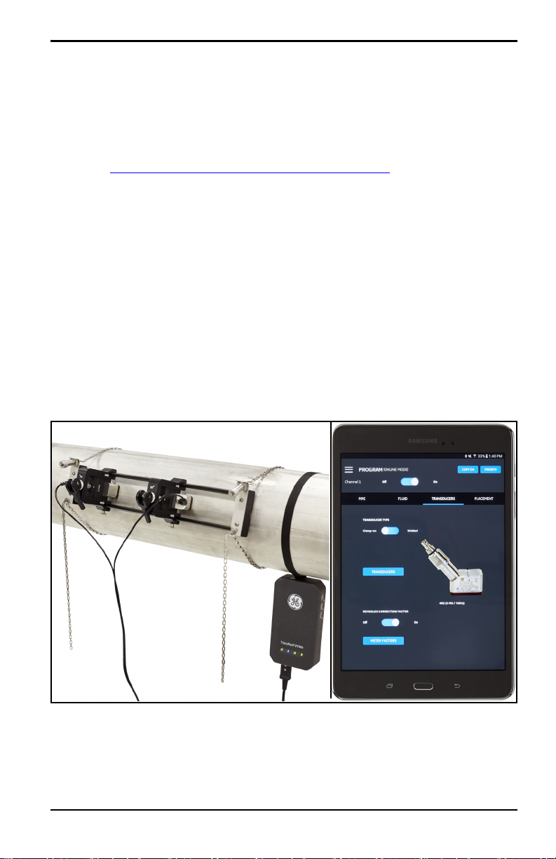
1.2 System Description
The PT900 is a portable flow transmitter for the measurement of liquid products. It
utilizes a new electronics platform and a simplified industrial design to make it
extremely easy to install and use. The system includes: a transmitter, a pair of
transducers, a new clamp-on fixture and a transducer cable (see Figure 1 below).
Optional accessories for the PT900 include: a tablet with the Android
operating system (see Figure 1 below), a thickness gauge, clamp-on temperature
transmitters and a clamp-on mounting fixture for pipes up to 48” in diameter. The
PT900 communicates with its remote display tablet via Bluetooth
for product support
®
or iOS
®
.
Figure 1: A PT900 Mounted on a Pipe and a Tablet (sold separately)
TransPort® PT900 User’s Manual 1
Page 18

Chapter 1. Introduction
[no content intended for this page]
2 TransPort® PT900 User’s Manual
Page 19
Chapter 2. Installation
Chapter 2. Installation
2.1 Introduction
To ensure safe and reliable operation of the PT900, the system must be installed in
accordance with established GE guidelines. Those guidelines are explained in
detail in this chapter and include the following topics:
• Unpacking the PT900 (see page 4)
• Mounting the PT900 Transmitter (see page 7)
• Installing the Clamp-On Fixture and Transducers (see page 7)
• Making the Electrical Connections (see page 33)
WARNING! The PT900 flow transmitter can measure the flow
rate of many fluids, some of which are potentially hazardous.
The importance of proper safety practices cannot be
overemphasized.
WARNING! Be sure to follow all applicable local safety codes
and regulations for installing electrical equipment and working
with hazardous fluids or flow conditions. Consult company safety
personnel or local safety authorities to verify the safety of any
procedure or practice.
ATTENTION EUROPEAN CUSTOMERS! To meet CE Mark and UL
Mark requirements, all cables must meet the specifications in
“Customer Cable Requirements for AIO/DIO Connections” on
page 161.
TransPort® PT900 User’s Manual 3
Page 20

Chapter 2. Installation
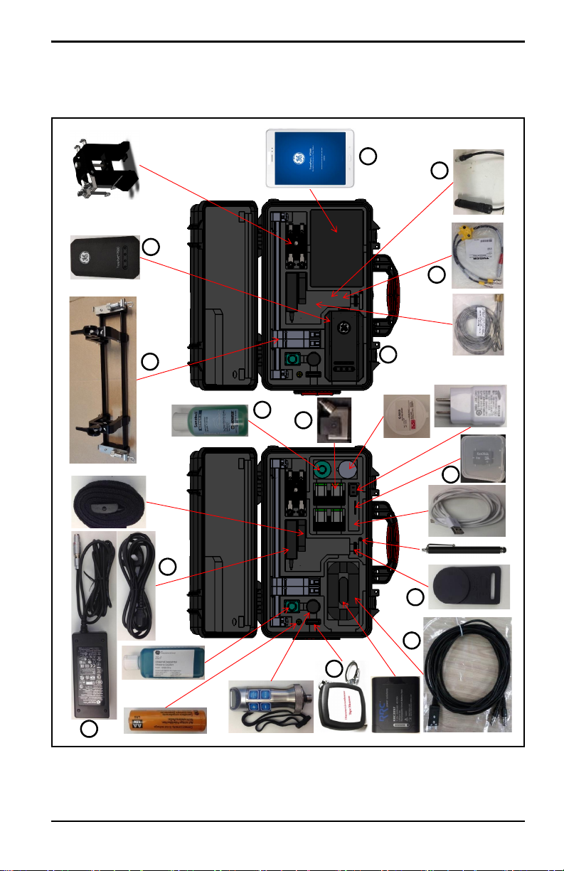
2.2 Unpacking the PT900
Before removing the PT900 from its carrying case (see the optional hard shell
carrying case in Figure 2 on page 5), inspect the contents of the case carefully.
Before discarding any of the packing materials, account for all components and
documentation listed on the packing slip. If anything is missing or damaged,
contact GE Customer Care immediately for assistance.
Because the PT900 may be ordered in many different configurations, the following
packing list is shown only as a typical example:
1. Transducers (2) 7. Case
2. Clamping Fixture 8. PT900 Power Supply
3. Transducer Cables 9. OD Tape
4. Transmitter 10. Couplant
5. Tablet Power Cord 11. PT900 Mounting Strap w/Magnet
6. SD Card
In addition to the standard components, the following optional components are
available for use with the PT900:
12. Tablet with protective case
13. Energy kit with an RTD module and an RTD cable for connection to the
PT900 transmitter
14. AIO cable with cabling box
• DIO cable with cabling box
• Battery charger
• Transducer extension cable up to 100 ft long
• 48" chain for the clamp-on fixture
4 TransPort® PT900 User’s Manual
Page 21
2.2 Unpacking the PT900 (cont.)
1
2
4
13
9
6
7
10
11
3
5
8
12
14
Chapter 2. Installation
Figure 2: PT900 in Hard Carrier Case
TransPort® PT900 User’s Manual 5
Page 22
Chapter 2. Installation
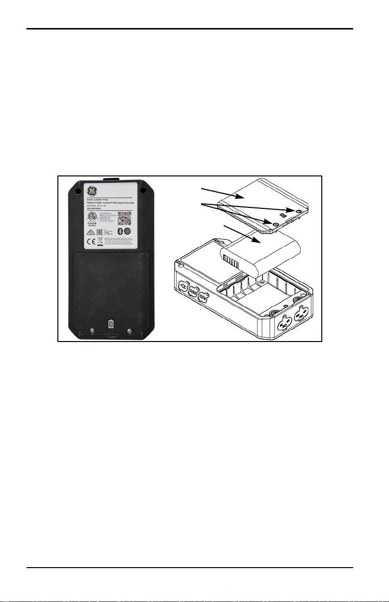
Cover
Battery Pack
Screws
2.3 Installing a Battery Pack in the Transmitter
To install a new battery pack in the transmitter (see Figure 3 below):
1. Using a slotted screwdriver, rotate the two quick-screws on the battery
cover 90° to open the transmitter.
2. Remove the existing battery pack.
3. Install the new battery pack in the battery compartment and replace the
battery cover. Secure the cover by tightening the two quick-screws.
Figure 3: Installing the Battery Pack in the Transmitter
6 TransPort® PT900 User’s Manual
Page 23
Chapter 2. Installation
Hard Carrier Case
Soft Strap
Magnetic Clamp
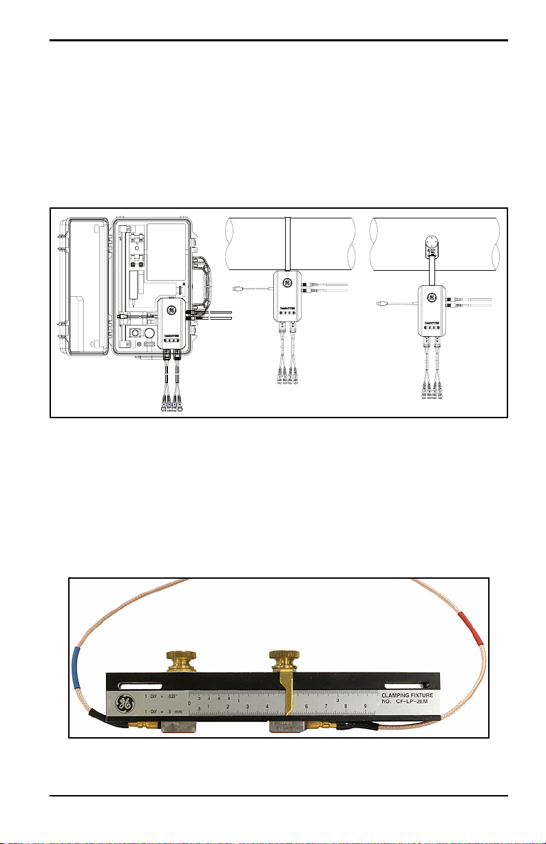
2.4 Mounting the PT900 Transmitter
The PT900 portable transmitter is housed in a durable rubberized enclosure suitable
for indoor or outdoor use. It can be placed in the hard carrier case or mounted on
the pipe with the either the soft strap or the magnetic clamp (see Figure 4 below).
Note: The pipe temperature must be between -20°C and about +40°C to safely
use the soft strap or magnetic clamp for mounting the transmitter.
Figure 4: PT900 Transmitter Mounting Options
2.5 Installing the Clamp-On Fixture and Transducers
This section describes in detail how to mount the standard PT9 clamp-on transducer
fixture on the pipe.
Note: Consult GE for instructions on installing the optional CF-LP clamping
fixture (shown in Figure 5 below).
Figure 5: CF-LP Clamping Fixture
TransPort® PT900 User’s Manual 7
Page 24
Chapter 2. Installation
Spacing
Flow Direction
PT900
Transmitter
Soft
Strap
Transducer
Cable
Chain
(x2)
Pipe (Not
Provided)
PT900
Fixture
Pair of CRR
Transducers
Important: Transducers shown
on top of pipe for clarity only.
Always mount on side of pipe!
2.5.1 A Sample Installation
For reference, a typical completed PT900 installation is shown in Figure 6 below.
Figure 6: Typical PT900 Installation
8 TransPort® PT900 User’s Manual
Page 25
Chapter 2. Installation
2.5.2 Transducer Spacing Calculation
ATTENTION! The required transducer spacing is calculated by the
APP after you program the PIPE, FLUID, TRANSDUCER and
PLACEMENT menus. Before proceeding with this installation, you
must complete the programming starting in Chapter 4.
Programming on page 63 up to “Viewing the Transducer Spacing”
on page 79. Use that calculated transducer spacing in the
following sections.
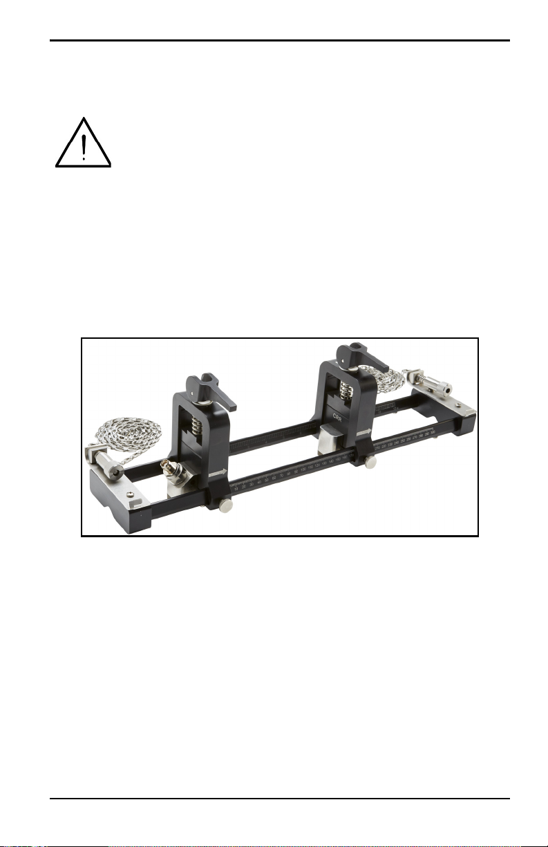
2.5.3 Mounting the PT9 Clamp-On Fixture
To mount the PT9 clamp-on fixture (see Figure 7 below) on the pipe, complete the
following steps:
Figure 7: PT9 Clamp-On Fixture with CRR Transducers
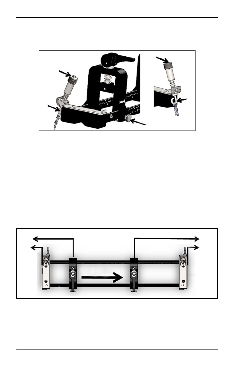
1. Before mounting the clamp-on fixture, refer to Figure 8 on page 10 and
proceed as follows:
• Ensure that the chain mechanism screws (A) that are attached to the
end piece flats are fully loosened.
• Ensure that the last link on the chain is secured within the chain
mechanism screw slot (
B) on both sides of the end piece.
• Ensure that the thumb screw (C) is tightened on the movable clamp so
that no motion is allowed during the mounting process.
TransPort® PT900 User’s Manual 9
Page 26
Chapter 2. Installation
A
B
C
A
B
2.5.3 Mounting the Clamp-On Fixture (cont.)
Figure 8: Bracket Preliminary Setup
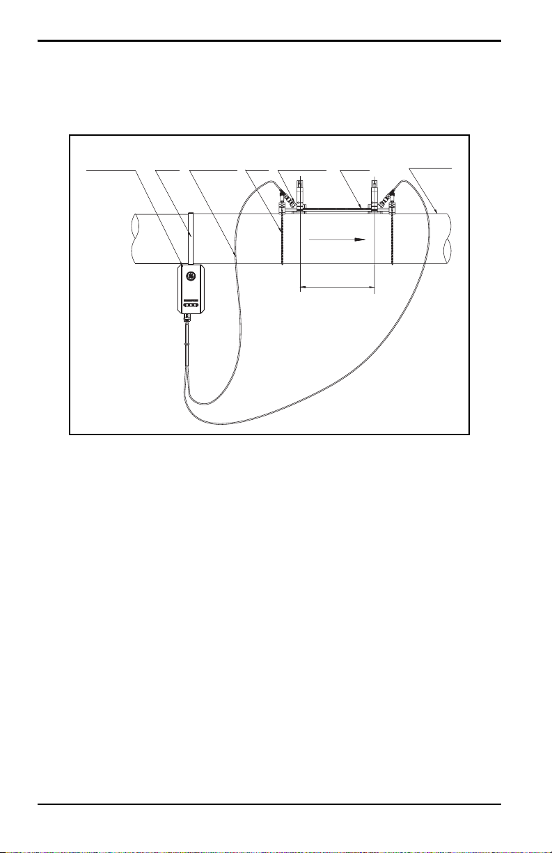
2. Select a clamp-on fixture mounting location on the pipeline which meets
the following requirements (see Figure 9 below):
• A straight pipe run of at least 10 nominal pipe diameters (with no
fittings or bends) before the upstream transducer
• A straight pipe run of at least 5 nominal pipe diameters (with no
fittings or bends) after the downstream transducer
• A clearance of at least 6” (150 mm) from the outer edge of each end
piece to the nearest joint, welding or flange in the pipeline
>10 Diameters >5 Diameters
Fitting
Joint
>6”/150 mm
Upstream Downstream
Flow Direction
Figure 9: Selecting the Pipe Location
10 TransPort® PT900 User’s Manual
Fitting
Joint
>6”/150 mm
Page 27
Chapter 2. Installation
>6”/150 mm
2.5.3 Mounting the Clamp-On Fixture (cont.)
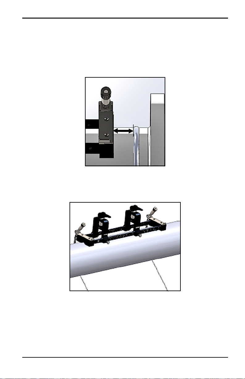
3. Adjust the clamp-on fixture position so that the outer edge of the closest
end piece is located at the chosen distance from the nearest inlet, outlet,
joint or fitting in the pipeline (see Figure 10 below).
Figure 10: Adjusting the Fixture Position
4. Place the clamp-on fixture on top of the pipe so that minimal effort is
required to maintain its position during installation (see Figure 11 below).
Figure 11: Fixture Placed on Top of Pipe
TransPort® PT900 User’s Manual 11
Page 28
Chapter 2. Installation
Slot
2.5.3 Mounting the Clamp-On Fixture (cont.)
5. Verify that the pipe rests in the small cutout slot on the bottom of the end
pieces (see Figure 12 below). Also, be sure that the scale markings on the
rail rod of the clamp-on fixture can be easily read after the installation has
been completed.
Figure 12: Cutout Slot
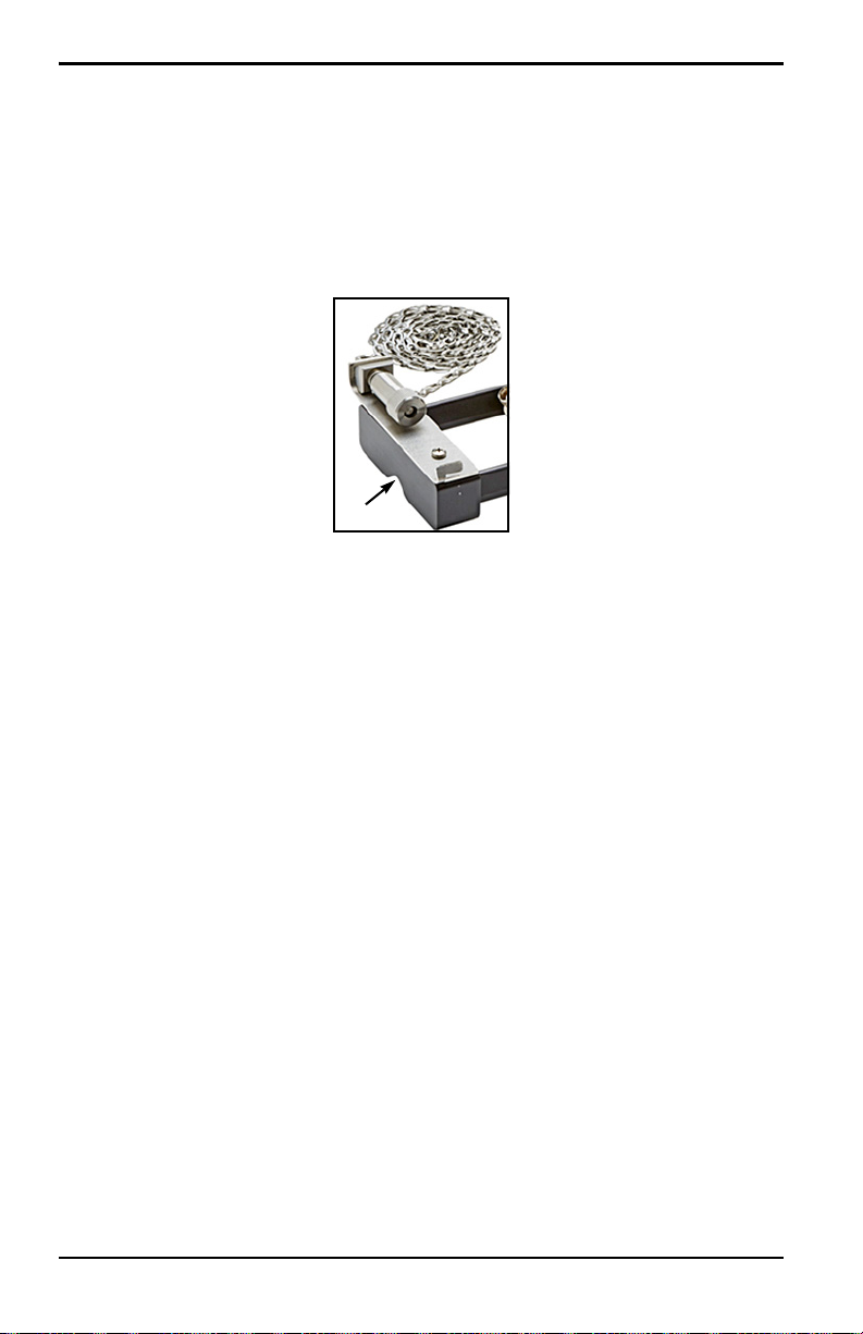
6. To install a chain around the pipe, refer to Figure 13 on page 13 and
complete the following steps:
a. Identify the chain screw mechanism, the end flat and the chain slot on
the clamping fixture end piece closest to the reference pipe fitting.
b. Unscrew the chain screw mechanism, then wrap the metal chain all
the way around the pipe.
c. Push down on the top of the chain screw mechanism and hold it
down. Then, pull the chain so that it is snug around the pipe and slide
the chain into the small slot located at the opposite side of the end
piece from the chain screw mechanism.
d. Release the chain screw mechanism and tighten it just enough to
remove any slack in the chain.
12 TransPort® PT900 User’s Manual
Page 29
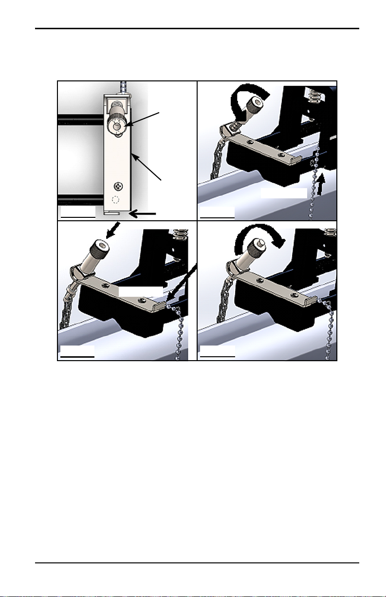
2.5.3 Mounting the Clamp-On Fixture (cont.)
Chain Slot
End Flat
Chain Screw
Mechanism
Step 6a
Step 6b
Step 6c
Step 6d
Unscrew
Press Down
Insert Chain
Tighten
End of Chain
Chapter 2. Installation
TransPort® PT900 User’s Manual 13
Figure 13: Installing a Chain
Page 30
Chapter 2. Installation
2.5.3 Mounting the Clamp-On Fixture (cont.)
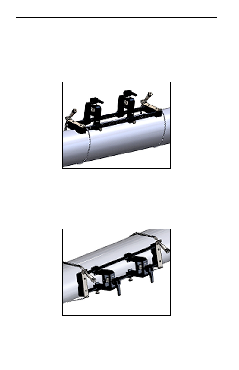
7. Repeat the previous steps to install the chain at the opposite end of the
clamp-on fixture (see Figure 14 below). The clamp-on fixture should be
firmly mounted to the pipe, but it should still be loose enough to allow
final alignment.
Figure 14: Fixture With Chains Installed
8. Rotate the fixture to the 3 o’clock or 9 o’clock position on the pipe (see
Figure 15 below). Installation on the top or bottom of the pipe is not
recommended. Make sure the pipe still rests in the cutout slot on the
bottom of both end pieces, to ensure that the fixture is parallel to the pipe
centerline.
Figure 15: Fixture Rotated to Horizontal Position
14 TransPort® PT900 User’s Manual
Page 31

Chapter 2. Installation
2.5.3 Mounting the Clamp-On Fixture (cont.)
9. After final alignment is complete, fully tighten both chains by turning the
nut on top of both chain screw mechanisms (see Figure 16 below) until the
chain is tight enough to resist any fixture movement.
Figure 16: Secure the Fixture to the Pipe
Note: As the last two steps affect each other, repeat them until the fixture is both
properly aligned and securely fastened to the pipe.
TransPort® PT900 User’s Manual 15
Page 32

Chapter 2. Installation
Clamp
Transducer
Hex Socket
Set Screw
Holder
Transducer Holder
Hex Socket Set Screw
2.5.4 Checking the Transducer Holders
Before installing the transducers into the clamp-on fixture, a transducer holder must
be attached to the each transducer. A transducer holder is installed on each
transducer by GE prior to shipment. Verify that your transducers have their holders
already installed and that they are secure. If so, you may skip this section.
A complete transducer assembly includes the following components:
• Clamp Holder: Permanently attached to the fixture clamp
• Transducer Holder: Semi-permanently attached to the transducer
• Transducer: Prior to mounting, the transducer is installed into the
transducer holder and secured with set screws. During mounting, the
transducer holder slides into the clamp holder and attaches with a plunger
If for some reason a transducer’s holder was not installed or has been removed,
refer to Figure 17 below and reinstall the holder as follows:
1. Slide the holder onto the top of the transducer so that the circle slots near
the top of the transducer sides are closely aligned with the filled holes on
the side of the transducer holder.
2. Screw the hex socket set screws from the transducer holder into the holes
of the transducer. These screws will lock the holder into place.
Figure 17: Transducer Assembly
16 TransPort® PT900 User’s Manual
Page 33

Chapter 2. Installation
Fixed Clamp
(at zero)
Movable Clamp
(at transducer spacing)
2.5.5 Installing the Transducers
To install the transducers into the mounting bracket, complete the following steps:
1. If necessary, loosen the thumb screw on the movable transducer clamp to
permit axial positioning.
2. Note that the fixed transducer clamp is set at the zero mark on the scale.
Position the movable transducer clamp so that it aligns with the mark on
the bracket’s graduated scale that matches the calculated transducer
spacing. Measurement markings should be read on the side of the
transducer clamp indicated by the arrows. Typically, set the holder on the
left to the zero position and the other holder to the desired spacing.
Figure 18: Secure the Fixture to the Pipe
Note: The required spacing between the transducers varies based on many
factors. The tablet APP automatically calculates your transducer spacing.
(see “Viewing the Transducer Spacing” on page 79).
3. Tighten the thumb screw to lock the movable transducer clamp into place,
being cautious not to disturb the established axial positioning.
TransPort® PT900 User’s Manual 17
Page 34

Chapter 2. Installation
2.5.5 Installing the Transducers (cont.)
4. Move both cams to the loaded position, so that the clamp holders rest in
their furthest radial position from the pipe (see Figure 19 below).
Figure 19: Loaded Cams
5. Apply the supplied couplant to both transducer faces (see Figure 20
below). The couplant displaces any air gaps between the transducer and
the pipe to ensure a uniform acoustic signal path. For pipes up to 14” OD,
do not apply couplant in the red areas shown; for pipes >14” OD, cover
the entire surface with couplant.
Note: Using a water-based lubricant as a couplant is not recommended for
heated or long-term installations.
Figure 20: Transducer Face with Couplant
18 TransPort® PT900 User’s Manual
Page 35

Chapter 2. Installation
2.5.5 Installing the Transducers (cont.)
6. Slide a transducer, which is already locked into its transducer holder, into
one of the clamp-on fixture’s clamp holders until the plunger from the top
of the transducer holder snaps into its position on the bottom of the clamp
holder (see Figure 21 below).
Important: The cable connectors on the mounted transducers must point away
from each other and toward opposite ends of the clamp-on fixture. To
assist in this requirement, the arrows on the end pieces help to
indicate the cable connector direction.
Figure 21: Inserting the Transducer
TransPort® PT900 User’s Manual 19
Page 36

Chapter 2. Installation
2.5.5 Installing the Transducers (cont.)
7. Release the cams on both transducer clamps so that the transducers are
pushed towards the pipe to ensure that the couplant completely fills the
gaps between the transducer faces and the pipe surface (see Figure 22
below).
CAUTION! When releasing the cams, the cam springs may
cause the cam to make hard contact with the clamp face. Any
objects or body parts between the contact faces could suffer
damage or minor injury.
Figure 22: Released Cams
Important: You must determine the required transducer spacing before
proceeding (see “Viewing the Transducer Spacing” on page 79).
20 TransPort® PT900 User’s Manual
Page 37

Chapter 2. Installation
2.5.6 Even and Odd-Traverse Installations
The transducers for a PT900 system may be installed in either of the following
configurations:
• Even-Traverse - The signal from one of the transducers traverses the fluid
flow an even number of times before being received by the other
transducer (two traverses is recommended for most applications).
• Odd-Traverse - The signal from one of the transducers traverses the fluid
flow once or an odd number of times before being received by the other
transducer.
2.5.6a Even-Traverse Installations (Spacing <305 mm/12 in.)
The standard PT900 clamp-on fixture is designed for an even-traverse installation,
as illustrated in Figure 23 below. After mounting the clamp-on fixture on the pipe,
refer to “Viewing the Transducer Spacing” on page 79 to adjust the spacing of the
transducer clamps to the required axial distance.
Figure 23: An Even-Traverse Installation (Top View)
Important: The installation above assumes a transducer spacing of
<305 mm/12 in. For even-traverse installations with transducer
spacings >305 mm/12 in., see “Even-Traverse Installations
(Spacing>305 mm/12 in.)” on page 28 for instructions.
TransPort® PT900 User’s Manual 21
Page 38

Chapter 2. Installation
Yoke
Screw
Loosened
Loosened
Completely
25 mm/1 in.
minimum
2.5.6b Odd-Traverse Installations
For an odd-traverse installation, the separate yoke included with the clamp-on
fixture is required (see Figure 24 below).
Figure 24: Yoke for Odd-Traverse Installations
Important: The clamping fixture must be installed before the yoke (see
“Mounting the PT9 Clamp-On Fixture” on page 9). You must
determine the required transducer spacing before proceeding (see
“Viewing the Transducer Spacing” on page 79).
To install the yoke, complete the following steps:
1. Loosen the yoke screw at least 25 mm/1 in. (all the way for pipes
<50 mm/2 in.) and loosen the J-Hooks all the way (see Figure 25 below).
Figure 25: Loosened Yoke Screw and J-Hooks
22 TransPort® PT900 User’s Manual
Page 39

Chapter 2. Installation
[Spacing
[Spacing
>305 mm/12 in.]
<305 mm/12 in.]
2.5.6b Odd-Traverse Installations (cont.)
2. Place the yoke on the top of the pipe (see Figure 26 below). If the required
transducer spacing is <305 mm/12 in., the yoke chain must be placed
within the clamping fixture as shown.
Figure 26: Yoke Placement On Top of Pipe
3. Wrap the yoke chains around the pipe and secure them to the yoke bracket,
TransPort® PT900 User’s Manual 23
as shown in Figure 27 below.
Figure 27: Yoke Chains Secured
Page 40

Chapter 2. Installation
[Spacing >305 mm/12 in.]
[Spacing <305 mm/12 in.]
Bracket Surfaces
Bracket Surfaces
2.5.6b Odd-Traverse Installations (cont.)
4. Rotate the yoke until it is located in a horizontal position on the opposite
side of the pipe from the previously installed clamping fixture, as shown
in Figure 28 below.
Figure 28: Yoke Rotated into Horizontal Position
5. Ensure that the top surfaces of the yoke bracket and the clamping fixture
brackets lie precisely in the same horizontal plane (see Figure 28 above).
Place the fixed clamp in the clamping fixture at zero on the scale.
Note: If the required axial spacing is 305-375 mm/12 in.-14.8 in., place the fixed
clamp at 100/4 in. on the scale instead of zero.
24 TransPort® PT900 User’s Manual
Page 41

2.5.6b Odd-Traverse Installations (cont.)
Fixed Clamp at Zero
Marking on Yoke
17.13 in. (435 mm)
Fixed Clamp
Marking
4.72 in.
on Yoke
at Zero
(120 mm)
6. Set the yoke axial position as follows:
• Spacing >305 mm/12 in. (435 mm/17.13 in. is used as an example):
Measure the required 435 mm/17.13 in. distance from the edge of the
fixed clamp to the marked line on the yoke (see Figure 29 below).
Figure 29: Yoke Set at 435 mm/17.13 in.
Chapter 2. Installation
• Spacing <305 mm (120 mm/4.72 in. is used as an example): Measure
the required 120 mm/4.72 in. distance from the edge of the fixed
clamp to the marked line on the yoke (see Figure 30 below).
TransPort® PT900 User’s Manual 25
Figure 30: Yoke Set at 120 mm/4.72 in.
Page 42

Chapter 2. Installation
2.5.6b Odd-Traverse Installations (cont.)
7. Tighten the nuts to secure the yoke to the pipe (see Figure 31 below).
Figure 31: Secure the Yoke
8. Loosen the yoke screw. Then, apply couplant to the transducer face and
insert the transducer into the yoke, as shown in Figure 32 below.
Figure 32: Insert Transducer into Yoke
26 TransPort® PT900 User’s Manual
Page 43

Chapter 2. Installation
[Spacing
[Spacing
<305 mm/12 in.]
>305 mm/12 in.]
2.5.6b Odd-Traverse Installations (cont.)
9. Tighten the yoke screw until the transducer firmly contacts the pipe. Your
completed odd-traverse installation should look like Figure 33 below.
TransPort® PT900 User’s Manual 27
Figure 33: Completed Odd-Traverse Installation (Top View)
Page 44

Chapter 2. Installation
Yoke
Screw
Loosened
Loosened
Completely
25 mm/1 in.
minimum
2.5.6c Even-Traverse Installations (Spacing>305 mm/12 in.)
For an even-traverse installation with a transducer spacing >305 mm/12 in., the
separate yoke included with the clamp-on fixture is required (see Figure 34 below).
Figure 34: Yoke for Even-Traverse With S>305 mm/12 in.
Important: The clamping fixture must be installed before the yoke (see
“Mounting the PT9 Clamp-On Fixture” on page 9). You must
determine the required transducer spacing before proceeding (see
“Viewing the Transducer Spacing” on page 79).
To install the yoke, complete the following steps:
1. Loosen the yoke screw at least 25 mm/1 in. (all the way for pipes
<50 mm/2 in.) and loosen the J-Hooks all the way (see Figure 25 below).
Figure 35: Loosened Yoke Screw and J-Hooks
28 TransPort® PT900 User’s Manual
Page 45

Chapter 2. Installation
2.5.6c Even-Traverse Installations (Spacing>305 mm/12 in.)
(cont.)
2. Place the yoke on the top of the pipe (see Figure 36 below). If the required
transducer spacing is <305 mm/12 in., the yoke chain must be placed
within the clamping fixture as shown.
Figure 36: Yoke Placement On Top of Pipe
3. Wrap the yoke chains around the pipe and secure them to the yoke bracket,
as shown in Figure 37 below.
Figure 37: Yoke Chains Secured
TransPort® PT900 User’s Manual 29
Page 46

Chapter 2. Installation
2.5.6c Even-Traverse Installations (Spacing>305 mm/12 in.)
(cont.)
4. Rotate the yoke until it is located in a horizontal position on the same side
of the pipe as the previously installed clamping fixture, as shown in
Figure 38 below.
Figure 38: Yoke Rotated into Horizontal Position
5. Ensure that the top surfaces of the yoke bracket and the fixed clamping
fixture bracket lie precisely in the same horizontal plane (see Figure 38
above).
30 TransPort® PT900 User’s Manual
Page 47

Chapter 2. Installation
Fixed Clamp
Yoke
435 mm/17.13 in.
at Zero
Marking
Line
2.5.6c Even-Traverse Installations (Spacing>305 mm/12 in.)
(cont.)
6. Place the fixed clamp in the clamping fixture at zero on the scale. As an
example, if the required transducer spacing is 435 mm/17.13 in., measure
the required 435 mm/17.13 in. distance from the edge of the fixed clamp
to the marked line on the yoke (see Figure 39 below).
Figure 39: Yoke Set at 435 mm/17.13 in.
7. Tighten the nuts to secure the yoke to the pipe (see Figure 40 below).
Figure 40: Secure the Yoke
TransPort® PT900 User’s Manual 31
Page 48

Chapter 2. Installation
2.5.6c Even-Traverse Installations (Spacing>305 mm/12 in.)
(cont.)
8. Loosen the yoke screw. Then, apply couplant to the transducer face and
insert the transducer into the yoke, as shown in Figure 41 below.
Figure 41: Insert Transducer into Yoke
9. Tighten the yoke screw until the transducer firmly contacts the pipe. Your
completed odd-traverse installation should look like Figure 42 below.
Figure 42: Completed Installation (Top View)
32 TransPort® PT900 User’s Manual
Page 49

Chapter 2. Installation
2.6 Making the Electrical Connections
Before taking measurements with the PT900, you must make all the necessary
cable connections to the transmitter. To wire your transmitter, complete the
following sections:
• Connecting the Line Power (see page 33)
• Connecting the Transducers (see page 35)
• Connecting the Digital Output (see page 36)
• Connecting the Analog Inputs and Output (see page 37)
• Using the USB Port (see page 38)
• Using the Bluetooth Wireless Interface (see page 38)
Note: For basic operation, you only need to connect the Transducer cables. The
I/O connections are required only if you intend to use those features.
After the PT900 is completely wired, proceed to Chapter 3, Initial Setup, to
configure the meter for operation.
2.6.1 Connecting the Line Power
An example of the PT900 transmitter product label is shown in Figure 43 below.
Be sure to power the transmitter only with the voltage specified on the label.
Figure 43: PT900 Transmitter Label
TransPort® PT900 User’s Manual 33
Page 50

Chapter 2. Installation
2.6.1 Connecting the Line Power (cont.)
WARNING! To ensure the safe operation, you must install and
operate the PT900 as described in this manual. Also, be sure to
follow all applicable safety codes and regulations for installing
electrical equipment in your area. The PT900 and its transducers
are designed for use only in general-purpose locations.
The PT900 is powered by either a 100-240 VAC wall mount plug-in module or by a
Lithium Ion high-energy rechargeable smart battery pack. In either case, you must
connect the power cord to the Power connector (see Figure 44 below).
In normal operation mode, the PT900 can be operated with a battery pack in the
transmitter. When you receive the PT900, the battery pack is not fully charged. To
charge the battery pack, you must use an external power adapter with an input
rating of 100-240VAC and output rating of 12VDC. When the AC power adapter is
connected to the transmitter, the battery LED will start flashing, which indicates
that the battery is charging. When the battery LED is continuously
that the battery is at full charge. When the external power adapter is removed, the
battery LED will be
Off.
On, it indicates
Figure 44: Transmitter Power Connection (Right Side)
WARNING! To ensure safe operation, do not turn the PT900 On
while the battery pack is being charged by an external power
adapter connected to a mains voltage of greater than 150VAC. If
the PT900 is turned
On in such a situation, make sure that you do
not touch the transducer connectors.
34 TransPort® PT900 User’s Manual
Page 51

Chapter 2. Installation
2.6.2 Connecting the Transducers
To connect the transducers, see Figure 45 below and proceed as follows:
1. Connect the cables from each of the transducers to the transmitter:
a. Connect the transducer cable with the
to the transmitter connector labeled
b. Connect the transducer cable with the
to the transmitter connector labeled
UP label on the cable connector
UP.
DN label on the cable connector
DN.
2. If your transmitter is configured for two channels, connect the second
transducer pair by repeating the above step.
3. Properly configure the transmitter to work properly with your specific
transducer type. See “Programming the Transducer Parameters” on
page 74 for instructions.
Important: Be sure to insert the cable connectors straight into the transmitter
connectors to avoid damaging the connectors.
Figure 45: Transducer Connections (Bottom)
TransPort® PT900 User’s Manual 35
Page 52

Chapter 2. Installation
2.6.3 Connecting the Digital Output
The PT900 provides one RS485/Modbus digital output and also supports a digital
frequency/pulse output and a totalizer/control gate input. Connect the digital output
as shown in Figure 46 below (see the cable to the right). The pin numbers for the
connector and the color code for the standard input/output cable are shown in
Ta bl e 1 below.
Table 1: DIO Cable Wiring Diagram
Connection Pin # Color Description
RS484- 1 Black RS485/Modbus Negative
RS485+ 2 Red RS485/Modbus Positive
RS485 COM 3 Green RS485/Modbus Common
DIO 4 White Digital IO Positive
DRTN 5 Yellow Digital IO Return
SHD 6 Silver Cable Shield
Figure 46: Transmitter I/O Connections (Right Side)
36 TransPort® PT900 User’s Manual
Page 53

Chapter 2. Installation
2.6.4 Connecting the Analog Inputs and Output
The PT900 provides one 0/4-20 mA analog current output and two 4-20 mA analog
inputs, with a switchable 16 V supply for loop-powered temperature transmitters.
Connect the analog inputs and output as shown in Figure 46 on page 36 (see the
cable to the left). The pin numbers for the connector and the color code for the
standard input/output cable are shown in Ta bl e 2 below.
Table 2: AIO Cable Wiring Diagram
Connection Pin # Color Description
Aout+ 1 Red 4-20mA OUTPUT
Aout- 2 Black 4-20mA RETURN
16VDC 3 Blue +16VDC OUTPUT
ARTN 4 Yellow ANALOG INPUTS RETURN
AIN1 5 Orange ANALOG INPUT 1
AIN2 6 Green ANALOG INPUT 2
SHD 7 Silver Cable Shield
Important: The Analog Output is an active mode type. Do not supply a 24V
supply to this circuit, as the circuit is powered by the transmitter.
2.6.5 Connecting the Energy Cables
The AIO port is commonly used for connecting a pair of energy cables to permit
energy measurements (see Figure 47 below).
Figure 47: Energy Cable Connection (Right Side)
TransPort® PT900 User’s Manual 37
Page 54

Chapter 2. Installation
2.6.6 Using the USB Port
The PT900 provides one USB2.0 full-speed interface. The receptacle is a
micro-USB Type B connector, as shown in Figure 48 below. Data logs and other
information from the transmitter’s embedded storage can be uploaded to a PC via
the USB port. In addition, the transmitter’s configuration files can be changed
directly via the USB port.
Figure 48: Transmitter USB Connector (Left Side)
2.6.7 Using the Bluetooth Wireless Interface
The PT900 comes equipped with an internal Bluetooth transceiver that enables
wireless communication between the transmitter and Bluetooth-enabled tablets.
The transmitter can then be configured by the PT900
tablet connected via the wireless Bluetooth interface. For more information on the
APP, see Chapter 3, Initial Setup.
APP software installed on a
2.7 Caring for the PT900 Batteries
The PT900 comes with a self-contained, built-in, rechargeable battery pack to
support portable operation. For optimum performance, these batteries require a
minimum of maintenance.
CAUTION! Use only GE-approved batteries and desktop
chargers, which are designed to maximize battery life. Using
other batteries or chargers voids your warranty and may cause
damage to the equipment.
CAUTION! For CE compliance, the PT900 is classified as a
battery-powered device, and it is not to be operated with the AC
power adapter connected.
38 TransPort® PT900 User’s Manual
Page 55

Chapter 2. Installation
2.7.1 Charging and Storing the Batteries
When you receive the PT900, you will need to initially charge the batteries. Also,
the batteries may need to be recharged if they have not been used for a long period
of time. The batteries must be charged for up to 3 hours to go from 0% (totally
depleted) to 100% (fully charged). When fully charged, the batteries provide
18-20 hours of continuous operation. An internal battery gauge indicates the
remaining power in the battery.
To charge the battery, simply plug the AC power adapter cord into the power jack
(see Figure 44 on page 34) and be sure the battery pack is installed in the
transmitter (see “Installing a Battery Pack in the Transmitter” on page 6). Whether
the PT900 is
internal transmitter battery charger automatically charges the battery. The battery
LEDs (see Figure 49 below) indicate the battery charging status.
On or Off, when the AC power adapter is plugged into line voltage the
Figure 49: Battery Charging Status LEDs
For optimal run time, charge the batteries only in temperatures from 32°F to 113°F
(0°C to 45°C). Otherwise, the batteries will not be properly charged and will have
significantly reduced run time. Store the batteries at temperatures ranging from
-4°F to 122°F (-20°C to 50°C). The recommended storage temperature range is
-4°F to 77°F (-20°C to 25°C). Extended storage at temperatures above 104°F
(40°C) could degrade battery performance and service life.
TransPort® PT900 User’s Manual 39
Page 56

Chapter 2. Installation
[Battery Panel]
2.7.2 Replacing the Batteries
CAUTION! Replace the PT900 batteries only with the specified
rechargeable batteries. The battery charges even when the unit
is
Off. Do not attempt to recharge non-rechargeable batteries.
To replace the battery pack:
1. Remove the rubber boot from the transmitter.
2. Open the panel on the back of the transmitter (see Figure 50 below).
3. Disconnect and remove the old battery pack.
4. Install the new battery pack.
5. Reinstall the panel and the rubber boot on the transmitter.
Figure 50: Battery Panel Location
40 TransPort® PT900 User’s Manual
Page 57

Chapter 2. Installation
2.7.3 Disposing of the Batteries
CAUTION! Never dispose of the batteries by incineration. Do
not attempt to disassemble or short-circuit the batteries. For
safety, do not handle a damaged or leaking battery.
CAUTION! Be sure to dispose of your batteries properly. In
some areas, battery disposal in business or household trash may
be prohibited. For safe disposal options, contact your nearest GE
authorized service center.
2.8 Powering On and Off
To operate the PT900, the power cord must be plugged into line voltage or the
battery pack must be charged as described in the previous sections.
CAUTION! For CE compliance, the PT900 is classified as a
battery-powered device, and it is not to be operated with the AC
power adapter connected. To comply with CE certification,
unplug the AC power adapter before operating the PT900.
WARNING! If the PT900 fails the backup battery test, you must
send the unit back to the factory for a battery replacement. Make
sure you keep the battery charged until you are ready to ship the
unit back to the factory. Before shipping, print out all of the log
and site data, or transfer it to your PC. Never dispose of the
battery by incineration. Do not attempt to disassemble or
short-circuit the battery pack. For safety, do not handle a
damaged or leaking battery.
TransPort® PT900 User’s Manual 41
Page 58

Chapter 2. Installation
Power
Bluetooth
Battery
Status
2.8 Powering On and Off (cont.)
To turn the PT900 On, press the Power On/Off button on the top of the transmitter
(see Figure 51 below) for about 3 seconds. Initially, only the Green Power LED
shows solid
show solid
On. However, after the system powers up completely, all the LEDs
On.
To turn the PT900
(see Figure 51 below) for about 3 seconds. All of the LEDs will turn
Off, press the Power On/Off button on the top of the transmitter
Off.
Figure 51: Transmitter Power Button (Top)
2.9 PT900 LED Indicators
The four colored LEDs on the front of the PT900 transmitter (see Figure 52 below)
provide real time information on the meter status. See the next page for details.
Figure 52: Transmitter LEDs (Front)
42 TransPort® PT900 User’s Manual
Page 59

2.9.1 Power LED
• Solid Green light when the meter is powered On
• No light when the meter is Off
• Blinking Green light when the meter is in power save mode
2.9.2 Bluetooth LED
Chapter 2. Installation
• Solid Blue light when Bluetooth
• Blinking Blue light when Bluetooth
pairing process
• Solid Red light when the meter is on and Bluetooth
to a transmitter
• No light when Bluetooth
®
is linked to a transmitter
®
is in the click-button to confirm
®
is in configuration mode
®
is idle or is not linked
2.9.3 Status LED
• Solid Green light when the meter is in measure mode without any errors
• Red light when an error occurs while the meter is in measure mode
• No light when the meter is in configure mode
2.9.4 Battery LED
• Solid Green light when the battery is fully charged (>99%), but the AC
adapter is connected
• Solid Green light when the battery level is high (>20%), but the AC
adapter is not connected
• Blinking Green light when the battery is not fully charged, but it is
charging with the AC adapter connected
• Red light when the battery level is low (20%) and the battery needs to be
charged immediately
• Blinking Red light when the battery level is low (10%) and the meter will
be out of power soon
• Light off when the meter is On, but the battery is completely discharged
and the AC adapter is connected
TransPort® PT900 User’s Manual 43
Page 60

Chapter 2. Installation
[no content intended for this page]
44 TransPort® PT900 User’s Manual
Page 61

Chapter 3. Initial Setup
Chapter 3. Initial Setup
3.1 Introduction
This chapter provides instructions for programming the PT900 flow meter via the
tablet APP prior to initial operation.
3.2 Charging the PT900 Transmitter and Tablet
Before proceeding, make sure that both the PT900 Transmitter and the Tab l et are
fully charged. The AC power adapters are shipped in the carry case. If either the
transmitter or the tablet cannot be powered On after charging, contact your GE
representative or visit www.gemeasurement.com
contact the tablet manufacturer for tablet assistance.
3.3 Installing or Updating the PT900 APP
The instructions in the following sections explain the procedures for downloading
the current version of the PT900 APP and installing it on your tablet.
3.3.1 Checking the APP Version
To check the APP version currently on your tablet, click on the About option in the
Help menu to open a screen similar to Figure 53 below. This screen displays
general information about the PT900. This information includes: model name,
instrument type, software version, and the copyright year of the APP.
for transmitter assistance or
Figure 53: The About Screen
TransPort® PT900 User’s Manual 45
Page 62

Chapter 3. Initial Setup
3.3.2 Installing or Updating the PT900 Android and iOS APP
Update your existing PT900 APP from one of the below options:
Android App
• Google Play Store: To obtain a newer version of the APP from Google
Play Store, search for “Transport PT900” and install it. Google Play Store
is the preferred method of installation because updates will automatically
be loaded to your tablet with the latest version of the application.
• QR Code or GE Website: To obtain a newer version of the APP, scan the
QR Code in Figure 54 below.
Figure 54: QR Code
Alternatively, download the latest version of the APP from the GE
website, go to the below URL and search for “TransPort PT900”
https://www.industrial.ai/download-center
• SD Card: To obtain a newer version of the APP from an SD card, plug the
SD card directly into the Tablet. Then, select the APK file from the SD
folder.
iOS App
• Minimum iOS Device Requirements: Device should have
- BLE 4.0 and above
- iOS version 11.0 and above
- Capacity: 16GB and above
• Apple App Store: To obtain a newer version of the APP from Apple App
Store, search for “Transport PT900” and install it. Apple App Store is the
only method to install the iOS application and updates will automatically
be loaded to your tablet with the latest version of the application.
46 TransPort® PT900 User’s Manual
Page 63

Chapter 3. Initial Setup
3.3.3 Installing the Tablet APP from the SD Card (Applicable only to Android APP)
To install the APP, complete the following steps:
1. Open the “My Files” folder on the tablet screen and select the APP from
the SD folder (see Figure 55 below).
Figure 55: The “My Files” Folder
2. In the tablet settings, enable the security option to allow the installation of
software from “Unknown sources” for this installation only (see Figure 56
below).
Figure 56: Security Settings
TransPort® PT900 User’s Manual 47
Page 64

Chapter 3. Initial Setup
3.3.3 Installing the Tablet APP from the SD Card (cont.)
3. Click on the APK file, and the Android operating system will verify the
checksum and signature for the file. Depending on whether this is an
initial installation or an update installation, you will see one of the screens
shown in Figure 57 below. Click
Note: If the file signature is not verified, the APP will be treated by the Android
operating system as an unrecognized APP.
INSTALL to begin the installation.
Figure 57: Initial (Left) and Update (Right) Installation Screens
48 TransPort® PT900 User’s Manual
Page 65

Chapter 3. Initial Setup
3.4 Pairing the Tablet and the Transmitter
To set up the APP and pair with the PT900 transmitter, complete the following
steps:
1. After the APP has been downloaded to your tablet, find the icon shown in
Figure 58 below on the tablet
Figure 58: PT900 APP Icon
2. While the APP is loading, you should see the initialization screen shown
in Figure 59 below.
APPS and click on it to launch the APP.
Figure 59: APP Loading Screen
TransPort® PT900 User’s Manual 49
Page 66

Chapter 3. Initial Setup
3.4 Setting Up the PT900 APP (cont.)
3. At the screen shown in Figure 60 below, select the desired language for
the APP and click
OK.
Figure 60: PT900 APP Language Options
4. At the License Agreement screen (see Figure 61 below), read the
agreement and then click
click
CANCEL to stop the APP installation.
AGREE to continue with the APP installation or
Figure 61: PT900 APP License Agreement
50 TransPort® PT900 User’s Manual
Page 67

Chapter 3. Initial Setup
3.4 Setting Up the PT900 APP (cont.)
5. At the Registration screen (see Figure 62 below), click OK to register your
PT900 or click
Note: If you skip the registration, the screen will popup as a reminder the first
five times you launch the APP and then it will never appear again.
6. After the APP finishes loading, the default Transmitter list is displayed.
During initial installation, this list is empty (see Figure 63 below).
CANCEL to skip the registration.
Figure 62: PT900 Registration
Figure 63: Initial Transmitter List
TransPort® PT900 User’s Manual 51
Page 68

Chapter 3. Initial Setup
3.4 Setting Up the PT900 APP (cont.)
7. To connect to a new PT900 transmitter, click SCAN. Pairing steps are
different for Android and iOS application. For Android, follow the below
steps (8 & 9) and for iOS, follow the steps 10 & 11.
Figure 64: Scanning Transmitter
Note: Your PT900 transmitter is identified by the serial number on its label (see
Figure 65 below).
Figure 65: Transmitter Serial Number
52 TransPort® PT900 User’s Manual
Page 69

Chapter 3. Initial Setup
Click Here
8. In Android, APP will search for all available transmitters via Bluetooth.
After the scan has been completed, any new transmitters which were
found are listed in the
AVAILABLE DEVICES section of the tablet screen (see
red arrow in Figure 66 below). Click on your transmitter to pair it with the
tablet via Bluetooth.
Important: Although Bluetooth is installed in many devices, the PT900 APP is
designed to filter out all devices except those with names of the form
PT900-Mxxxxxxxx.
Figure 66: Available Devices List
9. During the pairing process, PT900 security features require the user to
confirm the pairing (see Figure 67 below). When the Bluetooth pairing
request appears on the tablet (ignore the random passkey), click
OK to
continue. Then, confirm that the blue LED on the transmitter is flashing
and click the transmitter power button.
Important: The pairing is completed only after it is confirmed at both the tablet
and the transmitter. Otherwise, the pairing will fail.
TransPort® PT900 User’s Manual 53
Page 70

Chapter 3. Initial Setup
1. Click Here 2. See Blue LED
3. Click Button
Figure 67: Confirm the Pairing
For iOS:
10. In iOS, APP will search for all available transmitters via Bluetooth. After
the scan has been completed, any new transmitters which were found are
listed in the AVAILABLE DEVICES section of the tablet screen. Click on
your transmitter to pair it with the tablet via Bluetooth.
Figure 68: Available Devices List
Note: In Android, if Bluetooth is turned off then app can turn on the Bluetooth
programmatically but in iOS, there is no control over the Bluetooth to turn
on from application side.
Note: If you try to pair iPhone with firmware below 1.2.1, then you may see a
connection error popup. In such case after upgrading the firmware to
1.2.1 or above (supports iOS and android), turn the bluetooth off/on on
your device settings to start the connection again.
54 TransPort® PT900 User’s Manual
Page 71

Chapter 3. Initial Setup
1. Enter the Passkey - 843278 3. See Blue LED
4. Press the Power Button2. Click Pair
1
2
3
4
11. During the pairing process, PT900 security features require the user to
confirm the pairing (see Figure 69 below). When the Bluetooth pairing
request appears on the tablet, enter the passkey and click Pair. Then,
confirm that the blue LED on the transmitter is flashing and click the
transmitter power button within 10s. Passkey for this device is 843278.
Figure 69: Confirm the Pairing
TransPort® PT900 User’s Manual 55
Page 72

Chapter 3. Initial Setup
12. Click the BACK button on the tablet to return to the PT900 APP main
menu. Then, select your PT900 transmitter in the
list and click
PT900-M09160025 transmitter is selected from the list in Figure 70 below.
NEXT to open the Main Menu. For example, the
TRANSMITTERS PAIRED
Figure 70: Paired Transmitters List
Note: If desired, you may simulate the APP operation without connecting to the
transmitter. To do so, click the
Note: The transmitter can hold only a maximum of four paired devices at a time.
WORK OFFLINE option in Figure 70 above.
When you try to pair more than four devices, then the first paired device
will be automatically removed from the transmitter to allow the new
device for pairing.
56 TransPort® PT900 User’s Manual
Page 73

Chapter 3. Initial Setup
13. In iOS, if the power button is not pressed within 10s, then the pairing
process will fail at the transmitter end. Though it is not paired, this
unpaired device will also be displayed in the transmitter paired list. But
when you try to connect, below error pop-up will appear.
Figure 71: Connection Error
Important: To pair this transmitter again, user needs to remove the device
manually from PT900 APP and iPhone. To remove the device, refer to
“Removing paired devices from PT900 APP” on page 58 and
“Removing paired devices from iPhone/Tablet” on page 59.
TransPort® PT900 User’s Manual 57
Page 74

Chapter 3. Initial Setup
3.4.1 Removing paired devices from PT900 APP
1. Select the transmitter from the list that you want to remove and click Edit
button in the top right of the below screen.
Figure 72: Paired Transmitter Screen
2. Below screen appears. Click
Delete icon next to the transmitter name.
Figure 73: Delete icon
58 TransPort® PT900 User’s Manual
Page 75

Chapter 3. Initial Setup
3. Click OK on the pop-up that appears to confirm the deletion. Now the
device will be removed from the APP list.
Figure 74: Pop-up Screen
3.4.2 Removing paired devices from iPhone/Tablet
1. On iPhone/tablet Go to Settings > Bluetooth.
2. Find the device that you want to remove and click ⓘ icon next to it.
Figure 75: iPhone Bluetooth Settings Screen
TransPort® PT900 User’s Manual 59
Page 76

Chapter 3. Initial Setup
3. Click Forget This Device on the below screen.
Figure 76: Bluetooth Settings Screen
4. Click
Forget Device again on the below screen to confirm the deletion.
Now the device will be removed from the iPhone.
Figure 77: Confirm the Deletion
60 TransPort® PT900 User’s Manual
Page 77

Chapter 3. Initial Setup
3.5 Using the APP Main Menu and the Slide Menu
3.5.1 The Main Menu
After successfully installing the APP on the tablet and pairing a PT900 transmitter
with the tablet, the initial APP screen is the Main Menu shown in Figure 78 below.
Figure 78: APP Main Menu Screen
The available options in the APP Main Menu are:
• PROGRAM, which is used for selecting and configuring a channel.
• MEASURE, which is used for viewing real time measurements, error
reports and diagnostics information.
• LOGS, which is used for setting up log files and managing logs stored in
the PT900 transmitter.
• TRANSMITTER, which is used get information about transmitter,
performing calibrations, setting the error limits and saving the wave
sample.
• HELP, which is used for accessing detailed information and instructions for
your PT900.
TransPort® PT900 User’s Manual 61
Page 78

Chapter 3. Initial Setup
Swipe from left edge to right
Click Here
3.5.2 The Slide Menu (Applicable only to Android)
In Android, as an alternative to the Main Menu discussed in the previous section,
you may use the Slide Menu shown in Figure 79 below.
Figure 79: APP Slide Menu Screen
To access the Slide Menu, either click the icon in the top left corner of the
screen or swipe across the screen from the left edge to the right. The available
options in the APP Slide Menu are:
• PROGRAM, which is used for selecting and configuring a channel.
• MEASURE, which is used for viewing real time measurements, error
reports and diagnostics information.
• LOGS, which is used for setting up log files and managing logs stored in
the PT900 transmitter.
• HELP, which is used for accessing detailed information and instructions for
your PT900.
Note: In iOS, App main menu will appear if you swipe left edge to right.
62 TransPort® PT900 User’s Manual
Page 79

Chapter 4. Programming
Chapter 4. Programming
4.1 Configuring the Units of Measurement
The UNITS OF MEASUREMENT menu (see Figure 80 below) allows the user to
select the measurement units displayed by the PT900 in all of its screens.
Note: Because the choice of Metric or English units is reflected in all other menu
screens, this menu should be programmed first.
Figure 80: The Units of Measurement Menu
TransPort® PT900 User’s Manual 63
Page 80

Chapter 4. Programming
4.1 Configuring the Units of Measurement (cont.)
From the APP main menu, click Unit Options under the PROGRAM menu. This will
open the
UNITS OF MEASUREMENT menu shown in Figure 80 on page 63.
To program the
1. Move the slide switch at the top of the menu to either
UNITS OF MEASUREMENT, complete the following steps:
Metric or English to
select the desired PT900 global measurement units system.
2. Based on your selection above, the units for all of the PT900 measurement
parameters will be automatically populated with default units.
a. Some of the parameters have only one units of measure choice
available. The text boxes for these parameters are grayed out, and the
default units cannot be changed.
b. Some of the parameters have multiple units of measure choices
available. The text boxes for these parameters are active, and the
default units can be changed by opening the drop-down list and
selecting the desired units.
3. After you have completed your programming, click the
your choices or click the
CANCEL button to discard the changes.
OK button to save
64 TransPort® PT900 User’s Manual
Page 81

Chapter 4. Programming
4.2 Configuring a Channel
Selecting the PROGRAM>Channel option on the APP screen (see Figure 81 below)
enables you to set up a channel for measuring flow rate. The PT900 supports up to
two channels, channel
programmed information can be saved in a
1 and channel 2. They are programmed individually, and the
PRESETS file.
Figure 81: The Program Channel Menu
To completely configure a channel, the following menus must be programmed:
• PIPE (see “Programming the PIPE Menu” on page 67)
• FLUID (see “Programming the FLUID Menu” on page 70)
• TRANSDUCERS (see “Programming the TRANSDUCERS Menu” on
page 73)
• PLACEMENT (see “Programming the PLACEMENT Menu” on page 78)
TransPort® PT900 User’s Manual 65
Page 82

Chapter 4. Programming
4.2 Configuring a Channel (cont.)
Using Channel 1 as an example, refer to Figure 82 below and complete the
following steps:
1. Change the channel status from
Off to On. This will not only activate the
channel, but it will also activate the two programming buttons.
2. If the other channel has already been programmed, click the
COPY CH
button to copy all programming data from the other channel to the current
channel. In this example, it will copy the Channel 2 data into Channel 1 to
simplify the programming.
3. After the current channel has been programmed, click the
PRESETS button
to save the programming data to a file stored in the PT900 transmitter
memory. These site data files may be uploaded to the APP via the USB
link the next time the PT900 is installed at the same site.
Figure 82: Channel 1 Programming (Android Screen)
Figure 83: Channel 1 Programming (iOS Screen)
66 TransPort® PT900 User’s Manual
Page 83

Chapter 4. Programming
4.3 Programming the PIPE Menu
The PIPE menu allows the user to specify all pipe parameters that are required to
ensure accurate ultrasonic flow rate measurements. An example of this menu is
shown in Figure 84 below. See the following sub-sections for the options available
in programming the various pipe parameters.
Note: The measurement units used for all pipe parameters in these menus
depend on the choices made in the
UNITS OF MEASUREMENT menu.
Figure 84: The PIPE Menu
TransPort® PT900 User’s Manual 67
Page 84

Chapter 4. Programming
4.3.1 Pipe Materials
From the drop-down list of pipe materials supported by the PT900 transmitter,
select the pipe material for your application. For convenient reference, some of the
available options are shown in Ta bl e 3 below.
Table 3: Pipe Materials
Material Description Material Description
Other Any material Glass (Pyrex) Pyrex glass
Steel (Carbon) Carbon steel Glass (Flint) Flint glass
Steel (Stainless) Stainless steel Glass (Crown) Crown glass
Iron (Duct) Ductile iron Plastic (Nylon) Nylon
Iron (Cast) Cast iron Plastic (Polye) Polyethylene
Copper Copper Plastic (Polyp) Polypropylene
Aluminum Aluminum Plastic (PVC) Polyvinyl chloride
Brass Brass Plastic (Acryl) Acrylic plastics
30% Nickel 30% Ni/Cu alloy Plastic (Glass) Glass reinforced
10% Nickel 10% Ni/Cu alloy
plastic
Important: The pipe sound speed is automatically entered, based on the selected
pipe material. If
enter the correct sound speed for your specific pipe material.
OTHER is selected for the pipe material, be sure to
4.3.2 Pipe Dimensions
Be sure to enter the following information for your pipe:
• If the PIPE MATERIAL is any type of steel and the PIPE STANDARD is ANSI,
select the
Note: If the PIPE MATERIAL is not any type of steel, the above menu options are
not available.
NOMINAL size and the pipe SCHEDULE from the drop down list.
• In the OUTER DIAMETER box, enter the nominal outside diameter of the
pipe.
• In the WALL THICKNESS box, enter the wall thickness of the pipe.
68 TransPort® PT900 User’s Manual
Page 85

Chapter 4. Programming
4.3.3 Pipe Lining
If you entered YES in the LINING box, the LINING MATERIAL, LINING SOUND SPEED
and
LINING THICKNESS must be programmed to ensure accurate flow rate
measurements. From the drop-down list of pipe linings supported by the PT900
transmitter, select the pipe lining for your application. For convenient reference, the
list of available options is shown in Table 4 below.
Table 4: Available Pipe Linings
Material Description Material Description
Other Any material Mortar Mortar
Tar Epoxy Tar Epoxy Rubber Rubber
Pyrex Glass Pyrex Glass Teflon Teflon
Asbestos Cement Asbestos Cement
Important: The lining sound speed is automatically entered, based on the selected
lining material. If
enter the correct sound speed for your specific pipe lining.
OTHER is selected for the pipe lining, be sure to
Complete the lining programming by entering your
TransPort® PT900 User’s Manual 69
LINING THICKNESS.
Page 86

Chapter 4. Programming
4.4 Programming the FLUID Menu
The FLUID menu allows the user to specify all the parameters of the fluid flowing
through the pipe that are required to ensure accurate ultrasonic flow rate
measurements. An example of this menu is shown in Figure 85 below. See the
following sub-sections for the options available in programming the various fluid
parameters.
Note: The measurement units used for all fluid parameters in these menus
depend on the choices made in the
UNITS OF MEASUREMENT menu.
Figure 85: The FLUID Menu
70 TransPort® PT900 User’s Manual
Page 87

4.4 Programming the FLUID Menu (cont.)
To program the FLUID menu, complete the following steps:
Chapter 4. Programming
1. Select your
the expected
2. If the selected
constant which is automatically entered in the
3. If you selected
SPEED
4. In the
FLUID from the drop-down list (see Table 5 below) and enter
TEMPERATURE of the fluid during flow rate measurements.
FLUID is water or water-based, the SOUND SPEED is a
SOUND SPEED box.
OTHER as the FLUID, the automatic entry in the SOUND
box must be changed to the correct value by user.
DENSITY section, open the drop-down list and select Fixed or Active
depends on your system. If you choose Fixed, you will need to enter the
desired value in the
FIXED DENSITY section. If you choose Active, you will
be able to enter upto 10 Temperature/Density data points for your system
in a table on clicking
VIEW/EDIT TABLE as shown below.
Figure 86: Fluid menu density options
5. The fluid
KINEMATIC VISCOSITY (see GE document 916-119) is used to
calculate the Reynolds Number, which is then used calculate the Reynolds
Correction.
6. In the
REFERENCE DENSITY section, enter the value of reference density
which is used to calculate mass for CH1 and Ch2.
TransPort® PT900 User’s Manual 71
Page 88

Chapter 4. Programming
4.4 Programming the FLUID Menu (cont.)
7. The TRACKING WINDOW is used to detect the receive signal when the user
is unsure of the fluid sound speed. Set the
On or Off (the default setting is Off).
8. If the TRACKING WINDOW is On, enter the values for the MAX
SOUND SPEED and the MIN SOUND SPEED for the application.
TRACKING WINDOW to either
The available
WINDOW
FLUID types depends on the current setting for the TRACKING
(see Ta bl e 5 below).
Table 5: Available Fluid Types
Tracking Window Off Tracking Window On
Other Lube Oil (X200) Other
Water O il Wate r
Water/Glycol Methanol Water/Glycol
Sea Water Ethanol Oil
Oil (22°C) LN2 (-199°C)
Crude Oil Freon (R-12)
72 TransPort® PT900 User’s Manual
Page 89

Chapter 4. Programming
4.5 Programming the TRANSDUCERS Menu
The TRANSDUCERS menu allows the user to specify all the parameters of the
transducers that are required to ensure accurate ultrasonic flow rate measurements.
An example of this menu is shown in Figure 87 below. See the following
sub-sections for the options available in programming the transducers.
Note: The measurement units used for all transducer parameters in these menus
depend on the choices made in the
UNITS OF MEASUREMENT menu.
Figure 87: The TRANSDUCERS Menu
TransPort® PT900 User’s Manual 73
Page 90

Chapter 4. Programming
4.5.1 Programming the Transducer Parameters
To program your transducer parameters, refer to Figure 87 on page 73 and
complete the following steps:
1. On
TRANSDUCERS section and select your transducer model from the drop
down list.
Note: The GE Transducer Installation Guide for your transducer model provides
more detailed information on transducer mounting configurations.
Table 6: Available Clamp-On Transducers
Transducer Number Transducer Model Name
10 C-PT-N/0.5MHz
11 C-PT-N/2MHz
12 C-PT-H/0.5MHz
13 C-PT-H/1MHz
14 C-PT-M/2MHz
15 C-PT-H/0.5MHz
16 C-PT-H/1MHz
17 C-PT-H/2MHz
23* CF-LP-H/4MHz
24* CF-LP-N/4MHz
31 CF-WL/2MHz
401 C-RS/5MHz
402 C-RS/1MHz
403 C-RS/2MHz
407 UTXDR/2MHz
408 UTXDR/4MHz
505* C-RR/0.5MHz
510* C-RR/1MHz
520* C-RR/2MHz
591* C-RR/0.5MHz
592* C-RR/1MHz
601 C-AT/0.5MHz
602 C-AT/1MHz
603 C-AT/2MHz
*the most common transducers used with the PT900
74 TransPort® PT900 User’s Manual
Page 91

Chapter 4. Programming
4.5.1 Programming the Transducer Parameters (cont.)
2. If you select standard transducer from the drop down, you will need to
enter only the
other as your transducer model, few additional parameters will appear on
the screen (see Figure 88) and you must edit this data with the correct
specific information.
WEDGE TEMPERATURE (see Figure 87). But if you select
Figure 88: Transducer Menu parameters
a.
WEDGE TEMPERATURE: This parameter must be entered manually for
all transducers. It should be the average of the ambient temperature
and the process temperature.
b.
WEDGE SOUND SPEED: This parameter is entered automatically by
the PT900 for all
correct value provided by GE for
TransPort® PT900 User’s Manual 75
Standard transducers, but it must be edited with the
Other transducers.
Page 92

Chapter 4. Programming
4.5.1 Programming the Transducer Parameters (cont.)
c. WEDGE ANGLE: This parameter is entered automatically by the PT900
for all
Standard transducers, but it must be edited with the correct
value provided by GE for
Other transducers.
d. The
e. Open the
TW parameter is the time the transducer signal spends traveling
through the transducer and the transducer cable. Enter the value
provided by GE with your transducer.
FREQUENCY drop-down list and select the frequency at
which your transducer is designed to operate.
4.5.2 Setting the Reynolds Correction Factor
The REYNOLDS CORRECTION FACTOR can be set to either On or Off (see Figure 87
on page 73). This factor corrects the fluid velocity measured across a diametrical
path so that it more accurately represents the average fluid velocity across the entire
cross-sectional area of the pipe. The
turned
On for all clamp-on measurements.
REYNOLDS CORRECTION FACTOR should be
4.5.3 Programming the Meter Factor
To program the METER FACTOR, refer to Figure 87 on page 73 and complete the
following steps:
1. Click on the
below.
METER FACTOR button to open the menu shown in Figure 89
Figure 89: The Calibrate Factor Menu
76 TransPort® PT900 User’s Manual
Page 93

Chapter 4. Programming
4.5.3 Programming the Meter Factor (cont.)
2. The CALIBRATE FACTOR is used to calibrate or adjust the flow rate
readings of the PT900 to correspond with another flow rate reference. Use
the slide switch to set it to
On or Off, as desired.
3. Use the slide switch to set the
proceed to the appropriate step below:
K-FACTOR to either Single or Table. The,
• SINGLE: A single multiplier is applied to all PT900 measurements.
Generally, if the
should be set to 1.00. Otherwise, the typical range is 0.5 to 2.00.
Reynolds Correction Factor is On, the K-FACTOR
• TABLE (CALIBRATE FACTOR = On): A table is displayed (see Figure 90
below) which allows the user to enter multiple
points from several different sources or flow variables. These points
define a calibration curve for the PT900.
K-FACTORS for data
Figure 90: K-Factor Table
TransPort® PT900 User’s Manual 77
Page 94

Chapter 4. Programming
4.6 Programming the PLACEMENT Menu
The PLACEMENT menu allows the user to configure the mounting method of the
transducers, based on the programmed information in the
(see “Programming the TRANSDUCERS Menu” on page 73).
TRANSDUCERS menu
4.6.1 Viewing the Traverse Configuration
For CLAMP-ON transducers, one of the six possible TRAVERSE configurations
shown in Figure 91 below is displayed, as appropriate for your programmed
transducer information. Typically, a two-traverse installation is used.
Figure 91: Clamp-On Traverse Configurations
For
WETTED transducers, the values for the following parameters are listed, as
calculated from your programmed transducer information:
• PATH LENGTH
• AXIAL LENGTH
78 TransPort® PT900 User’s Manual
Page 95

Chapter 4. Programming
4.6.2 Viewing the Transducer Spacing
The TRANSDUCER SPACING screen (see Figure 92 below) shows the value
calculated by the PT900 for the correct distance between the upstream and
downstream transducers, based on your programmed transducer data. This value
should be used when installing your transducer clamping fixture on the pipe.
Figure 92: Transducer Spacing Value
TransPort® PT900 User’s Manual 79
Page 96

Chapter 4. Programming
4.6.2a Custom Transducer Spacing
If your transducers were installed with a spacing different from the value calculated
by the APP, refer to Figure 93 below and input the actual spacing as follows:
Note: Be sure that, if the installed spacing you input is larger than the calculated
value, it is not more than 10% above the calculated value.
1. Enter your actual transducer spacing in the units specified by your system
UNITS setting.
2. Click the
OK button to accept the new value.
Figure 93: Custom Transducer Spacing
80 TransPort® PT900 User’s Manual
Page 97

Chapter 4. Programming
4.6.2b Zero Flow Validation
Important: You must make sure that the fluid in your pipe is not flowing before
proceeding.
After the flow in the pipeline is verified to be static, refer to Figure 94 below and
calibrate the zero flow setting by completing the following steps:
1. Click the
2. Click the
VELOCITY input control.
ZERO FLOW button, and then click the OK button.
3. If the displayed velocity value is not zero, record the displayed velocity.
4. Enter the recorded velocity value from the previous step in the
FLOW CUTOFF
box and click the OK button.
MINIMUM
Figure 94: Zero Flow Validation
TransPort® PT900 User’s Manual 81
Page 98

Chapter 4. Programming
4.6.2c Sound Speed Validation
When the speed of sound in your fluid does not equal published values, refer to
Figure 95 below and set the
steps:
SOUND SPEED LEVEL by completing the following
1. Click the
SOUND SPEED LEVEL input control.
2. Enter your actual sound speed in the units specified by your system
setting.
3. Click the
OK button to accept the new value.
UNITS
Figure 95: Sound Speed Validation
Important: You have now completed the programming of the PIPE, FLUID,
TRANSDUCER and PLACEMENT menus. Click on the GO TO MEASURE
button to change to the measurement display or click the
LOG DATA
button to begin logging data.
82 TransPort® PT900 User’s Manual
Page 99

Chapter 4. Programming
4.7 Configuring the Program Options
Note: The programming instructions in this section are only required if you will
be using any of the options listed below.
From the
PROGRAM menu, as highlighted in Figure 96 below. This will open the Program
Options
The
APP main menu, click the Program Options sub-menu under the
menu shown in Figure 97 on page 84.
Program Options menu includes the following tabs:
• ENERGY (see page 85)
• INPUTS (see page 87)
• OUTPUTS (see page 88)
• USER FUNCTIONS (see page 93)
Proceed to the appropriate section for programming instructions.
Figure 96: The PROGRAM Menu
TransPort® PT900 User’s Manual 83
Page 100

Chapter 4. Programming
4.7 Configuring the Program Options (cont.)
Figure 97: The Program Options Menu
84 TransPort® PT900 User’s Manual
 Loading...