

GE Transport Pro User manual

Transport Pro
™
Patient Monitor
Service Manual
2012659-002 Revision A

127(Due to continuing product innovation, specifications in this manual are subject to change without
notice.
Listed below are GE Medical Systems Information Technologies trademarks used in this document. All other
trademarks contained herein are the property of their respective owners.
DASH, RAC, SOLAR, TRAM, TRAM-NET, TRAM-RAC, TRIM KNOB, and UNITY NETWORK are
trademarks of GE Medical Syst ems Information Technologies registered in the United States Patent and
Trademark Office.
12SL, MENTOR, TRANSPORT PRO, and UNITY are trademarks of GE Medical Systems Information
Technologies.
© GE Medical Systems Information Technologies, 2003. All rights reserved.
T-2 Transport Pro Patient Monitor Revision A
2012659-002 1 July 2003

Contents
1 Introduction . . . . . . . . . . . . . . . . . . . . . . . . . . . . . . . . . . . . 1-1
Manual Information . . . . . . . . . . . . . . . . . . . . . . . . . . . . . . . . . . . . . . . . . . . . . . . . . . 1-3
Revision History . . . . . . . . . . . . . . . . . . . . . . . . . . . . . . . . . . . . . . . . . . . . . . . . . . .1-3
Manual Purpose . . . . . . . . . . . . . . . . . . . . . . . . . . . . . . . . . . . . . . . . . . . . . . . . . . .1-3
Manual Conventions . . . . . . . . . . . . . . . . . . . . . . . . . . . . . . . . . . . . . . . . . . . . . . .1-3
Intended Audience . . . . . . . . . . . . . . . . . . . . . . . . . . . . . . . . . . . . . . . . . . . . . . . . .1-3
Safety Information . . . . . . . . . . . . . . . . . . . . . . . . . . . . . . . . . . . . . . . . . . . . . . . . . . . 1-4
Responsibility of the Manufacturer . . . . . . . . . . . . . . . . . . . . . . . . . . . . . . . . . . . . .1-4
General . . . . . . . . . . . . . . . . . . . . . . . . . . . . . . . . . . . . . . . . . . . . . . . . . . . . . . . . .1-4
Warnings, Cautions, and Notes . . . . . . . . . . . . . . . . . . . . . . . . . . . . . . . . . . . . . . .1-5
Equipment Symbols . . . . . . . . . . . . . . . . . . . . . . . . . . . . . . . . . . . . . . . . . . . . . . . . . 1-6
Service Information . . . . . . . . . . . . . . . . . . . . . . . . . . . . . . . . . . . . . . . . . . . . . . . . . . 1-8
Service Requirements . . . . . . . . . . . . . . . . . . . . . . . . . . . . . . . . . . . . . . . . . . . . . .1-8
Equipment Identification . . . . . . . . . . . . . . . . . . . . . . . . . . . . . . . . . . . . . . . . . . . . .1-8
2 Equipment Overview . . . . . . . . . . . . . . . . . . . . . . . . . . . . . 2-1
Equipment Description . . . . . . . . . . . . . . . . . . . . . . . . . . . . . . . . . . . . . . . . . . . . . . . 2-3
The Transport Pro Monitor . . . . . . . . . . . . . . . . . . . . . . . . . . . . . . . . . . . . . . . . . . .2-3
Basic System Components . . . . . . . . . . . . . . . . . . . . . . . . . . . . . . . . . . . . . . . . . .2-3
Optional Components . . . . . . . . . . . . . . . . . . . . . . . . . . . . . . . . . . . . . . . . . . . . . .2-4
Front View . . . . . . . . . . . . . . . . . . . . . . . . . . . . . . . . . . . . . . . . . . . . . . . . . . . . . . .2-5
Back View . . . . . . . . . . . . . . . . . . . . . . . . . . . . . . . . . . . . . . . . . . . . . . . . . . . . . . .2-6
Side Views . . . . . . . . . . . . . . . . . . . . . . . . . . . . . . . . . . . . . . . . . . . . . . . . . . . . . . .2-7
Controls . . . . . . . . . . . . . . . . . . . . . . . . . . . . . . . . . . . . . . . . . . . . . . . . . . . . . . . . .2-8
Indicators . . . . . . . . . . . . . . . . . . . . . . . . . . . . . . . . . . . . . . . . . . . . . . . . . . . . . . . .2-8
Tram Module Compatibility . . . . . . . . . . . . . . . . . . . . . . . . . . . . . . . . . . . . . . . . . . . 2-10
Theory of Operation . . . . . . . . . . . . . . . . . . . . . . . . . . . . . . . . . . . . . . . . . . . . . . . . . 2-12
Block Diagram . . . . . . . . . . . . . . . . . . . . . . . . . . . . . . . . . . . . . . . . . . . . . . . . . . .2-12
Display Assembly . . . . . . . . . . . . . . . . . . . . . . . . . . . . . . . . . . . . . . . . . . . . . . . . .2-12
Power Supply . . . . . . . . . . . . . . . . . . . . . . . . . . . . . . . . . . . . . . . . . . . . . . . . . . . .2-12
Processor/Power Management Circuit Board Assembly . . . . . . . . . . . . . . . . . . .2-13
Revision A Transport Pro Patient Monitor i
2012659-002

3 Installation . . . . . . . . . . . . . . . . . . . . . . . . . . . . . . . . . . . . . 3-1
Requirements . . . . . . . . . . . . . . . . . . . . . . . . . . . . . . . . . . . . . . . . . . . . . . . . . . . . . . . 3-3
Location . . . . . . . . . . . . . . . . . . . . . . . . . . . . . . . . . . . . . . . . . . . . . . . . . . . . . . . . .3-3
Tools . . . . . . . . . . . . . . . . . . . . . . . . . . . . . . . . . . . . . . . . . . . . . . . . . . . . . . . . . . .3-4
Mounting Options . . . . . . . . . . . . . . . . . . . . . . . . . . . . . . . . . . . . . . . . . . . . . . . . . .3-4
Install or Remove the Tram Chute . . . . . . . . . . . . . . . . . . . . . . . . . . . . . . . . . . . . . . 3-5
Install or Remove a Module . . . . . . . . . . . . . . . . . . . . . . . . . . . . . . . . . . . . . . . . . . . 3-7
Connections . . . . . . . . . . . . . . . . . . . . . . . . . . . . . . . . . . . . . . . . . . . . . . . . . . . . . . . . 3-8
Connectors . . . . . . . . . . . . . . . . . . . . . . . . . . . . . . . . . . . . . . . . . . . . . . . . . . . . . . .3-8
Connect the Transport Pro Monitor to the Tram Module . . . . . . . . . . . . . . . . . . . .3-8
Power Up . . . . . . . . . . . . . . . . . . . . . . . . . . . . . . . . . . . . . . . . . . . . . . . . . . . . . . . .3-9
Setup/Configure the Monitor . . . . . . . . . . . . . . . . . . . . . . . . . . . . . . . . . . . . . . . . . 3-10
Set Patient-Monitor Type . . . . . . . . . . . . . . . . . . . . . . . . . . . . . . . . . . . . . . . . . . .3-10
Set Monitor Defaults Password . . . . . . . . . . . . . . . . . . . . . . . . . . . . . . . . . . . . . .3-11
Set Unit Name . . . . . . . . . . . . . . . . . . . . . . . . . . . . . . . . . . . . . . . . . . . . . . . . . . .3-11
Set Bed Number . . . . . . . . . . . . . . . . . . . . . . . . . . . . . . . . . . . . . . . . . . . . . . . . .3-12
Set Country Selection . . . . . . . . . . . . . . . . . . . . . . . . . . . . . . . . . . . . . . . . . . . . .3-12
Set Language . . . . . . . . . . . . . . . . . . . . . . . . . . . . . . . . . . . . . . . . . . . . . . . . . . . .3-13
Completion . . . . . . . . . . . . . . . . . . . . . . . . . . . . . . . . . . . . . . . . . . . . . . . . . . . . . .3-13
Installing Software . . . . . . . . . . . . . . . . . . . . . . . . . . . . . . . . . . . . . . . . . . . . . . . . . . 3-14
4 Maintenance . . . . . . . . . . . . . . . . . . . . . . . . . . . . . . . . . . . 4-1
Maintenance Schedule . . . . . . . . . . . . . . . . . . . . . . . . . . . . . . . . . . . . . . . . . . . . . . . 4-3
Manufacturer Recommendations . . . . . . . . . . . . . . . . . . . . . . . . . . . . . . . . . . . . . .4-3
Manufacturer Responsibility . . . . . . . . . . . . . . . . . . . . . . . . . . . . . . . . . . . . . . . . . .4-3
Visual Inspection . . . . . . . . . . . . . . . . . . . . . . . . . . . . . . . . . . . . . . . . . . . . . . . . . . . . 4-4
Cleaning . . . . . . . . . . . . . . . . . . . . . . . . . . . . . . . . . . . . . . . . . . . . . . . . . . . . . . . . . . . 4-5
Cleaning Precautions . . . . . . . . . . . . . . . . . . . . . . . . . . . . . . . . . . . . . . . . . . . . . . .4-5
Exterior Cleaning . . . . . . . . . . . . . . . . . . . . . . . . . . . . . . . . . . . . . . . . . . . . . . . . . .4-5
Lithium-Ion Battery . . . . . . . . . . . . . . . . . . . . . . . . . . . . . . . . . . . . . . . . . . . . . . . . . . 4-6
The Impact of Lithium-Ion Battery Technology on the Battery . . . . . . . . . . . . . . . .4-6
How to Improve the Performance of the Battery . . . . . . . . . . . . . . . . . . . . . . . . . .4-6
How to Identify the Capacity of the Battery . . . . . . . . . . . . . . . . . . . . . . . . . . . . . .4-7
How to Replace the Battery . . . . . . . . . . . . . . . . . . . . . . . . . . . . . . . . . . . . . . . . .4-11
How to Charge the Battery . . . . . . . . . . . . . . . . . . . . . . . . . . . . . . . . . . . . . . . . . .4-12
How to Condition the Battery . . . . . . . . . . . . . . . . . . . . . . . . . . . . . . . . . . . . . . . .4-13
How to Store the Battery . . . . . . . . . . . . . . . . . . . . . . . . . . . . . . . . . . . . . . . . . . .4-14
How to Wake Up the Battery . . . . . . . . . . . . . . . . . . . . . . . . . . . . . . . . . . . . . . . .4-14
ii Transport Pro Patient Monitor Revision A
2012659-002

How to Recycle the Battery . . . . . . . . . . . . . . . . . . . . . . . . . . . . . . . . . . . . . . . . .4-15
The Cadex SMart Two+ Charger . . . . . . . . . . . . . . . . . . . . . . . . . . . . . . . . . . . . .4-16
Electrical Safety Tests . . . . . . . . . . . . . . . . . . . . . . . . . . . . . . . . . . . . . . . . . . . . . . . 4-17
General . . . . . . . . . . . . . . . . . . . . . . . . . . . . . . . . . . . . . . . . . . . . . . . . . . . . . . . .4-17
Recommendations . . . . . . . . . . . . . . . . . . . . . . . . . . . . . . . . . . . . . . . . . . . . . . . .4-17
Power Outlet Test . . . . . . . . . . . . . . . . . . . . . . . . . . . . . . . . . . . . . . . . . . . . . . . .4-18
Ground (Earth) Integrity . . . . . . . . . . . . . . . . . . . . . . . . . . . . . . . . . . . . . . . . . . . .4-19
Ground (Earth) Wire Leakage Current Tests . . . . . . . . . . . . . . . . . . . . . . . . . . . .4-21
Enclosure Leakage Current Test . . . . . . . . . . . . . . . . . . . . . . . . . . . . . . . . . . . . .4-22
Test Completion . . . . . . . . . . . . . . . . . . . . . . . . . . . . . . . . . . . . . . . . . . . . . . . . . .4-23
Checkout Procedure . . . . . . . . . . . . . . . . . . . . . . . . . . . . . . . . . . . . . . . . . . . . . . . . 4-24
General . . . . . . . . . . . . . . . . . . . . . . . . . . . . . . . . . . . . . . . . . . . . . . . . . . . . . . . .4-24
Required Tools/Special Equipment . . . . . . . . . . . . . . . . . . . . . . . . . . . . . . . . . . .4-24
Monitor Power-up Tests . . . . . . . . . . . . . . . . . . . . . . . . . . . . . . . . . . . . . . . . . . . .4-25
Battery Tests . . . . . . . . . . . . . . . . . . . . . . . . . . . . . . . . . . . . . . . . . . . . . . . . . . . .4-26
Display Tests . . . . . . . . . . . . . . . . . . . . . . . . . . . . . . . . . . . . . . . . . . . . . . . . . . . .4-28
Speaker Test . . . . . . . . . . . . . . . . . . . . . . . . . . . . . . . . . . . . . . . . . . . . . . . . . . . .4-28
Tram Module Communication Test . . . . . . . . . . . . . . . . . . . . . . . . . . . . . . . . . . .4-29
Checkout Procedures Completion . . . . . . . . . . . . . . . . . . . . . . . . . . . . . . . . . . . .4-29
PM Form . . . . . . . . . . . . . . . . . . . . . . . . . . . . . . . . . . . . . . . . . . . . . . . . . . . . . . .4-29
Repair Log . . . . . . . . . . . . . . . . . . . . . . . . . . . . . . . . . . . . . . . . . . . . . . . . . . . . . .4 -30
5 Troubleshooting . . . . . . . . . . . . . . . . . . . . . . . . . . . . . . . . 5-1
Required Tools/Special Equipment . . . . . . . . . . . . . . . . . . . . . . . . . . . . . . . . . . . . . 5-3
Diagnostic Tests . . . . . . . . . . . . . . . . . . . . . . . . . . . . . . . . . . . . . . . . . . . . . . . . . . . . 5-4
Main Processor Board LEDs . . . . . . . . . . . . . . . . . . . . . . . . . . . . . . . . . . . . . . . . . . . 5-5
Troubleshooting Procedures . . . . . . . . . . . . . . . . . . . . . . . . . . . . . . . . . . . . . . . . . . 5-6
Symptom: Blank Display . . . . . . . . . . . . . . . . . . . . . . . . . . . . . . . . . . . . . . . . . . . .5-6
Symptom: Dim Display . . . . . . . . . . . . . . . . . . . . . . . . . . . . . . . . . . . . . . . . . . . . . .5-7
Symptom: Poor Display Quality . . . . . . . . . . . . . . . . . . . . . . . . . . . . . . . . . . . . . . .5-8
Symptom: No Audible Alarms . . . . . . . . . . . . . . . . . . . . . . . . . . . . . . . . . . . . . . . .5-9
Symptom: Unable to Lower Alarm Volume . . . . . . . . . . . . . . . . . . . . . . . . . . . . .5-10
Symptom: Speaker Buzz . . . . . . . . . . . . . . . . . . . . . . . . . . . . . . . . . . . . . . . . . . .5-11
Symptom: Unresponsive Buttons . . . . . . . . . . . . . . . . . . . . . . . . . . . . . . . . . . . . .5-12
Symptom: Monitor Resets . . . . . . . . . . . . . . . . . . . . . . . . . . . . . . . . . . . . . . . . . .5-13
Service Menus . . . . . . . . . . . . . . . . . . . . . . . . . . . . . . . . . . . . . . . . . . . . . . . . . . . . . 5-14
Boot Loader Service Menu . . . . . . . . . . . . . . . . . . . . . . . . . . . . . . . . . . . . . . . . .5-14
Service Mode Menu . . . . . . . . . . . . . . . . . . . . . . . . . . . . . . . . . . . . . . . . . . . . . . .5-16
Review Errors . . . . . . . . . . . . . . . . . . . . . . . . . . . . . . . . . . . . . . . . . . . . . . . . . . .5-18
Error Log Information . . . . . . . . . . . . . . . . . . . . . . . . . . . . . . . . . . . . . . . . . . . . . .5-20
Error Logs . . . . . . . . . . . . . . . . . . . . . . . . . . . . . . . . . . . . . . . . . . . . . . . . . . . . . .5-20
Revision A Transport Pro Patient Monitor iii
2012659-002

Battery Alarms and Messages . . . . . . . . . . . . . . . . . . . . . . . . . . . . . . . . . . . . . . . . 5-22
Alarm Conditions . . . . . . . . . . . . . . . . . . . . . . . . . . . . . . . . . . . . . . . . . . . . . . . . .5-22
Battery Error Message . . . . . . . . . . . . . . . . . . . . . . . . . . . . . . . . . . . . . . . . . . . . .5-23
Power Source Tests . . . . . . . . . . . . . . . . . . . . . . . . . . . . . . . . . . . . . . . . . . . . . . . . 5-24
Wall Receptacle . . . . . . . . . . . . . . . . . . . . . . . . . . . . . . . . . . . . . . . . . . . . . . . . . .5-24
Power Cord and Plug . . . . . . . . . . . . . . . . . . . . . . . . . . . . . . . . . . . . . . . . . . . . . .5-25
Error Messages . . . . . . . . . . . . . . . . . . . . . . . . . . . . . . . . . . . . . . . . . . . . . . . . . . . . 5-26
6 Parts List, Drawings, and Replacement . . . . . . . . . . . . . 6-1
Ordering Parts . . . . . . . . . . . . . . . . . . . . . . . . . . . . . . . . . . . . . . . . . . . . . . . . . . . . . . 6-3
Service Parts . . . . . . . . . . . . . . . . . . . . . . . . . . . . . . . . . . . . . . . . . . . . . . . . . . . . . . . 6-4
Field Replaceable Units (FRUs) . . . . . . . . . . . . . . . . . . . . . . . . . . . . . . . . . . . . . .6-4
FRU Parts Lists . . . . . . . . . . . . . . . . . . . . . . . . . . . . . . . . . . . . . . . . . . . . . . . . . . .6-5
Other Components . . . . . . . . . . . . . . . . . . . . . . . . . . . . . . . . . . . . . . . . . . . . . . . .6-14
Interconnection Diagram . . . . . . . . . . . . . . . . . . . . . . . . . . . . . . . . . . . . . . . . . . . . 6-15
Exploded Views . . . . . . . . . . . . . . . . . . . . . . . . . . . . . . . . . . . . . . . . . . . . . . . . . . . . 6-16
Transport Pro Display Assembly — PN 2012150-001, Rev. A . . . . . . . . . . . . . .6-16
Transport Pro Display Tram Chute — PN 2011432-001, Rev. A . . . . . . . . . . . . .6-19
Disassembly/Assembly of FRUs . . . . . . . . . . . . . . . . . . . . . . . . . . . . . . . . . . . . . . 6-20
Guidelines for Disassembly . . . . . . . . . . . . . . . . . . . . . . . . . . . . . . . . . . . . . . . . .6-20
Disassembly Procedures . . . . . . . . . . . . . . . . . . . . . . . . . . . . . . . . . . . . . . . . . . .6-22
After Assembly . . . . . . . . . . . . . . . . . . . . . . . . . . . . . . . . . . . . . . . . . . . . . . . . . . .6-52
Appendix A – Technical Specifications . . . . . . . . . . . . . .A-1
Product Specification . . . . . . . . . . . . . . . . . . . . . . . . . . . . . . . . . . . . . . . . . . . . . . . . A-3
Display . . . . . . . . . . . . . . . . . . . . . . . . . . . . . . . . . . . . . . . . . . . . . . . . . . . . . . . . . .A-3
Battery Operation . . . . . . . . . . . . . . . . . . . . . . . . . . . . . . . . . . . . . . . . . . . . . . . . . .A-3
Environmental Specifications . . . . . . . . . . . . . . . . . . . . . . . . . . . . . . . . . . . . . . . . .A-3
DC Power Supply . . . . . . . . . . . . . . . . . . . . . . . . . . . . . . . . . . . . . . . . . . . . . . . . . .A-4
Operating Conditions . . . . . . . . . . . . . . . . . . . . . . . . . . . . . . . . . . . . . . . . . . . . . . .A-4
Storage Conditions . . . . . . . . . . . . . . . . . . . . . . . . . . . . . . . . . . . . . . . . . . . . . . . .A-4
Product Durability Specifications . . . . . . . . . . . . . . . . . . . . . . . . . . . . . . . . . . . . . .A-4
Physical Specification . . . . . . . . . . . . . . . . . . . . . . . . . . . . . . . . . . . . . . . . . . . . . . . . A-5
Transport Pro Monitor . . . . . . . . . . . . . . . . . . . . . . . . . . . . . . . . . . . . . . . . . . . . . . A-5
Tram Chute . . . . . . . . . . . . . . . . . . . . . . . . . . . . . . . . . . . . . . . . . . . . . . . . . . . . . .A-5
Certification . . . . . . . . . . . . . . . . . . . . . . . . . . . . . . . . . . . . . . . . . . . . . . . . . . . . . .A-5
iv Transport Pro Patient Monitor Revision A
2012659-002

1 Introduction
Revision A Transport Pro Patient Monitor 1-1
2012659-002

For your notes
1-2 Transport Pro Patient Monitor Revision A
2012659-002

Manual Informatio n
Revision History
Each page of this manual has the document part number and revision
letter at the bottom of the page. The revision letter identifies the
document’s update level. The revision history of this document is
summarized below.
Manual Purpose
This manual supplies technical information for service representatives
and technical personnel so they can maintain the equipment to the
assembly level. Use it as a guide for maintenance and electrical repairs
considered field repaira ble. Where necessary the manual identifies
additional sources of relevant information and technical assistance.
Introduction: Manual Information
Revision History
Revision Date Comment
A 1 July 2003 Initial release of this manual.
Manual Conventions
Product References
Intended Audience
See the operator’s manual for the instructions necessary to opera te the
equipment safely in accordance with its function and intended use.
Term Definition
monitor The whole unit including the display, Tram chute and Tram module.
display The display only. This does not include the Tram chute or the Tram
module.
This manual is intended for service representatives and technical
personnel who maintain, troubleshoot, or repair this equipment.
Revision A Transport Pro Patient Monitor 1-3
2012659-002

Introduction: Safety Information
Safety Information
Responsibility of the Manuf acturer
GE is responsible for the effects of safety, reliability, and performance
only if:
Assembly operations, extensions, readju stments, modifications, or
repairs are carried out by persons authorized by GE.
The electrical installation of the relevant room complies with the
requirements of the appropriate regulations.
The equipment is used in accordance with the instructions for use.
General
This device is intended for use under the direct supervision of a licensed
health care practitioner.
This device is not intended for home use.
Federal law restricts this device to be sold by or on the order of a
physician.
Contact GE for information before connecting any devices to the
equipment that are not recommended in this manual.
Parts and accessories used must meet t he requireme nts of t he appli cable
IEC 601 series safety standards, and/or the system configuration must
meet the requirements of the IEC 60601-1-1 medical electrical systems
standard.
Periodically, and whenever the integrity of the device is in doubt, test all
functions.
The use of ACCESSORY equipment not complying with the equivalent
safety requirements of this equipment may lead to a reduced level of
safety of the resulting system. Consideration relating to the choice shall
include:
use of the accessory in the PATIENT VICINITY; and
evidence that the safety certification of the ACCESSORY has been
performed in accordance to the appropriate IEC 60601-1 and/or IEC
60601-1-1 harmonized national standard.
If the installation of the equipment, in the USA, will use 240V rather
than 120V, the source must be a center-tapped, 240V, single-phase
circuit.
1-4 Transport Pro Patient Monitor Revision A
2012659-002

Introduction: Safety Information
Warnings, Cautions, and Notes
The terms danger, warning, and caution are used throughout this
manual to point out hazards and to designate a degree or level or
seriousness. Familiarize yourself with their definitions and significance.
Hazard is defined as a source of potential injury to a person.
DANGER indicates an imminent hazard which, if not avoided, will
result in death or serious injury.
WARNING indicates a potential hazard or unsafe practice which, if not
avoided, could result in death or serious injury.
CAUTION indicates a potential hazard or unsafe practice which, if not
avoided, could result in minor personal injury or product/property
damage.
NOTE provides application tips or other useful information to assure
that you get the most from your equipment.
Revision A Transport Pro Patient Monitor 1-5
2012659-002
Equipment Symbols
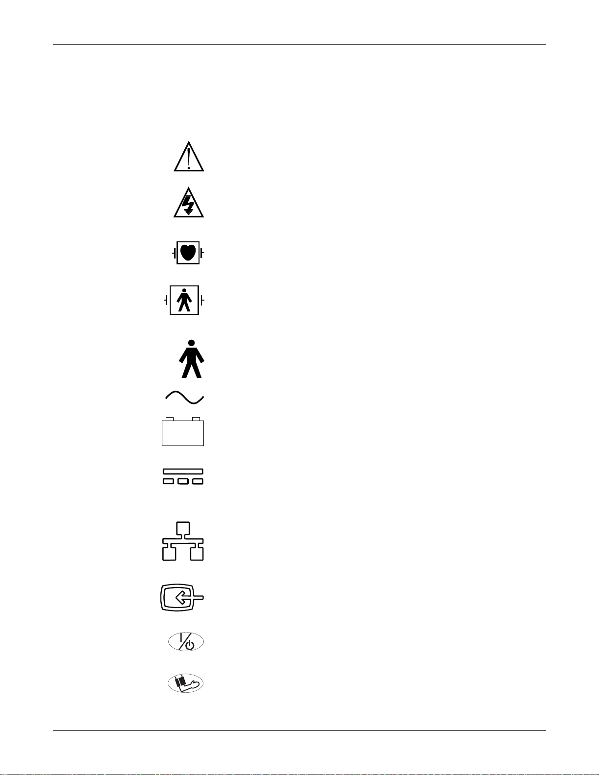
Some of the following symbols appear on the equipment.
ATTENTION: Consult accompanying documents before using the equipment.
In Europe, this symbol means dangerous or high voltage. In the United States, this symbol
represents the caution notice below:
To reduce the risk of electric shock, do NOT remove cover (or back). Refer servicing to
qualified personnel.
Defibrillator-proof type CF equipment; type CF equipment is specifically designed for
applications where a conductive connection directly to the heart is established. The paddles
indicate the equipment is defibrillator proof.
Defibrillator-proof type BF equipment; type BF equipment is suitable for intentional external
and internal application to the patient, excluding direct cardiac application. Type BF
equipment is type B equipment with an F-type isolated (floating) part. The paddles indicate
the equipment is defibrillator proof.
Introduction: Equipment Symbols
Type B equipment; type B equipment is suitable for intentional external and internal
application to the patient, excluding direct cardiac application.
Alternating current (AC)
Battery
592A
DC power
833A
Ethernet
593A
Video In
834A
POWER
814A
NBP GO/STOP
816A
1-6 Transport Pro Patient Monitor Revision A
2012659-002

4P41
Introduction: Equipment Symbols
ZERO ALL
817A
SILENCE ALARM/ADMIT
818A
Medical Equipment
With respect to electric shock, fire and mechanical hazards only in accordance with UL
2601-1, and CAN/CSA C22.2 NO. 601.1.
Revision A Transport Pro Patient Monitor 1-7
2012659-002
Service Information
c
Service Requirements
Follow the service requirements listed below.
Equipment Identification
Introduction: Service Information
Refer equipment servicing to GE authorized service personnel only.
Any unauthorized attempt to repair equipment under warr anty voids
that warranty.
It is the user’ s responsi bili ty to report the n eed fo r service to GE or to
one of their authorized agents.
Failure on the part of the responsible individual, hospital, or
institution using this equipment to implement a satisfactory
maintenance schedule may cause undue equipment failure and
possible health hazards.
Regular maintenance, irrespective of usage, is essential to ensure
that the equipment will always be functional when required.
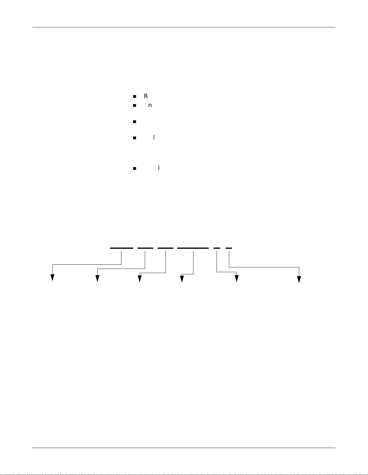
Product Code
AAC = Transport Pro
Year
Manufactured
(00-99)
00 = 2000
01 = 2001
02 = 2002
(and so on)
Every GE device has a unique serial number for identification. A sample
of the info rmation found on a serial number label is shown below.
### ## ## #### # #
Fiscal Week
Manufactured
(01-52)
Product Serial
Number
(sequential number
up to 9999 units per
week)
Manufacturing Site
P = Bangalore
N = Freiburg
S = Juarez
H = Jupiter
G = Milwaukee
W = Wuxi
Miscellaneous Characteristi
P = prototype
R = refurbished equipment
X = default
1-8 Transport Pro Patient Monitor Revision A
2012659-002

2 Equipment Overview
Revision A Transport Pro Patient Monitor 2-1
2012659-002

For your notes
2-2 Transport Pro Patient Monitor Revision A
2012659-002

Equipment Overview: Equipment Description
Equipment Descrip ti on
The Transport Pro Monitor
The monitor is a portable display for the Tram modules to provide a
means of displaying patient parameters and data from the Tram during
patient transport.
Two rechargeable, lithium-Ion batteries provide power to the display and
Tram during transport. An external power supply connector is provided
to power the unit from an AC power source and to recharge the batteries .
An asynchronous communication port is provided for communications
with the Tram module. Unity Ne twork (twisted-p air Etherne t) hardware
is provided on the display, but Unity Network functionality is not
available in V1A.
The Transport Pro monitoring system consists of the following
components:
Transport Pro display/processing unit
Tram modu le
Tram chute
Data cable (“curly” cable)
Batteries (two)
Optional external power supply (AC power-to DC-power converter)
Optional external battery charger
Basic System Components
Transport Pro Display/Processing Unit
The display/processing unit consists of the following sub-components.
Flat-panel display
Main control/indicator panel
Processor/Power management circuit board and speaker
Rear housing
Tram Module
The monitor uses a Tram module to acquire patient data. See “Tram
Module Compatibility” on page 2-10 for a list of compatible Tram
modules.
Tram Chute
The detachable Tram chute is used to secure one Tram module to the
monitor during patient transport.
Revision A Transport Pro Patient Monitor 2-3
2012659-002

Data Cable
Batteries
Optional Components
External Power Supply
Equipment Overview: Equipment Description
A cable is connected between the Tram module and the display. This
cable provides a communication pathway between the two devices.
The monitor is designed to operate on battery power during transport or
whenever AC power is interrupted. A complete battery management
system allows you to obtain max imum battery perf ormance. Audib le and
visual alarms alert you when loss of power is imminent and on-screen
capacity gauges indicate battery charge condition and capacity.
The external power suppl y provides power to the display and to the Tram
module. When batteries are inserted into the monitor, the external power
supply will also charge the batteries.
Cadex SMart Two+ External Battery Charger
The external battery charger can hold and charge up to two batteries.
When you select the Target Capacity switch on the charger, the
charger compares the battery’s performance to a 60%, 70%, or 80% target
capacity set on the battery charger. If the b at te ry fa il s to mee t th e tar g et
performance, the battery charger will prompt you to condition the
battery. If the battery does not hold a charge, then the battery charger
will illuminate a “fail” light.
2-4 Transport Pro Patient Monitor Revision A
2012659-002
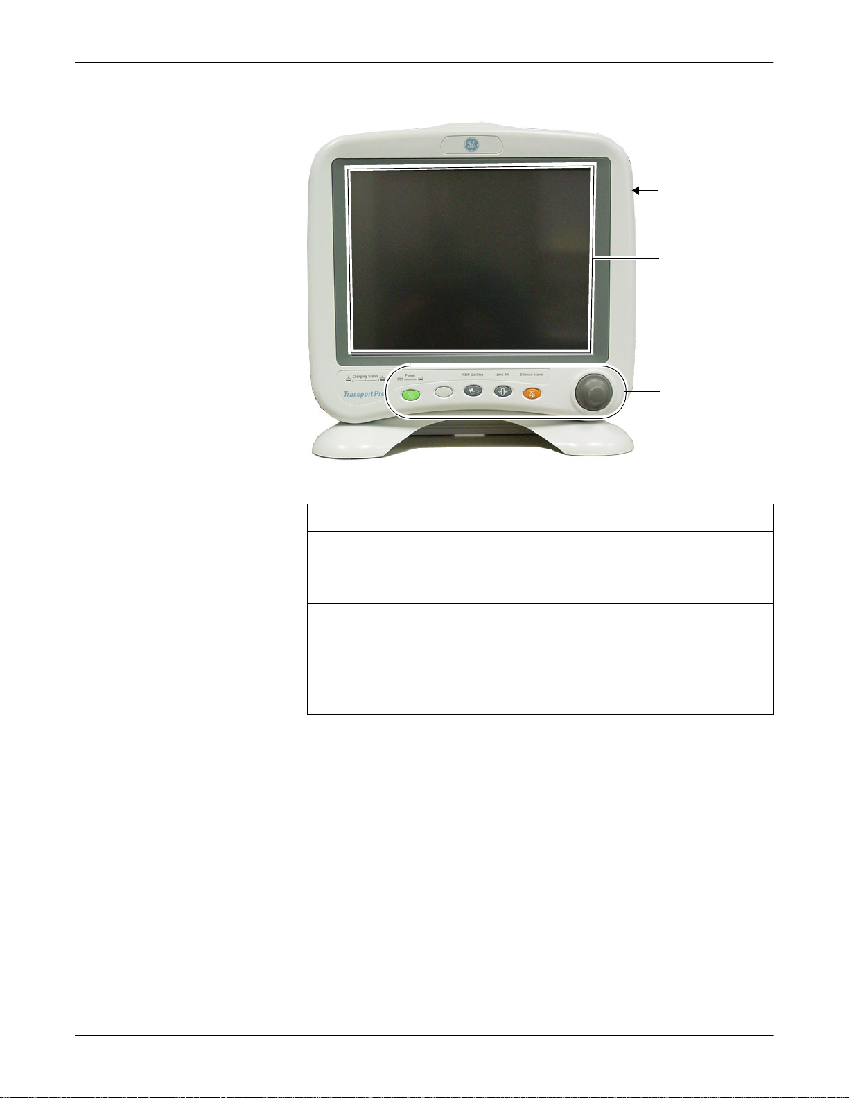
Front View
Equipment Overview: Equipment Description
A
B
C
839A
Name Description
A Display Connect the Tram chute and insert a Tram module
to create a transport monitor.
B Display screen View waveform and text data.
C Controls and indicators Use the control keys and the Trim Knob control to
configure the monitor and to view or enter data.
See “Controls” on page 2-8. The indicators provide
information about the power source and the
charging status of the batteries. See “Indicators” on
page 2-8.
Revision A Transport Pro Patient Monitor 2-5
2012659-002
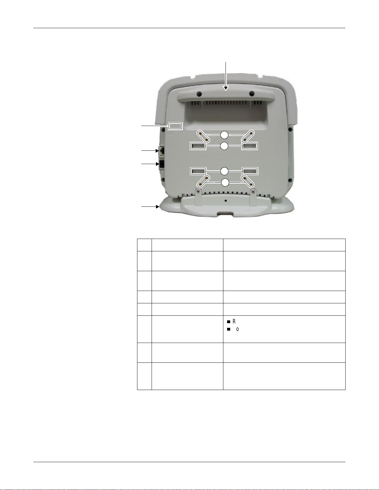
Back View
B
C
D
A
E
Equipment Overview: Equipment Description
F
G
G
F
840A
Name Description
A Handle Use to carry the display or the transport monitor
from place to place.
B Serial number label See “Equipment Identification” on page 1-8 for a
description of the serial number.
C Video In connector See “Connectors” on page 3-8.
D Ethernet connector See “Connectors” on page 3-8.
E Foot
Remove to attach the display to an IV pole.
Connect to the display when placing the monitor
on a table top or shelf.
F Mounting points Use the mounting points to attach a standard IV
pole clamp.
G Tram chute mounting slots Insert and slide the Tram chute mounting tabs. Be
sure to insert and secure the Tram chute mounting
screw.
2-6 Transport Pro Patient Monitor Revision A
2012659-002
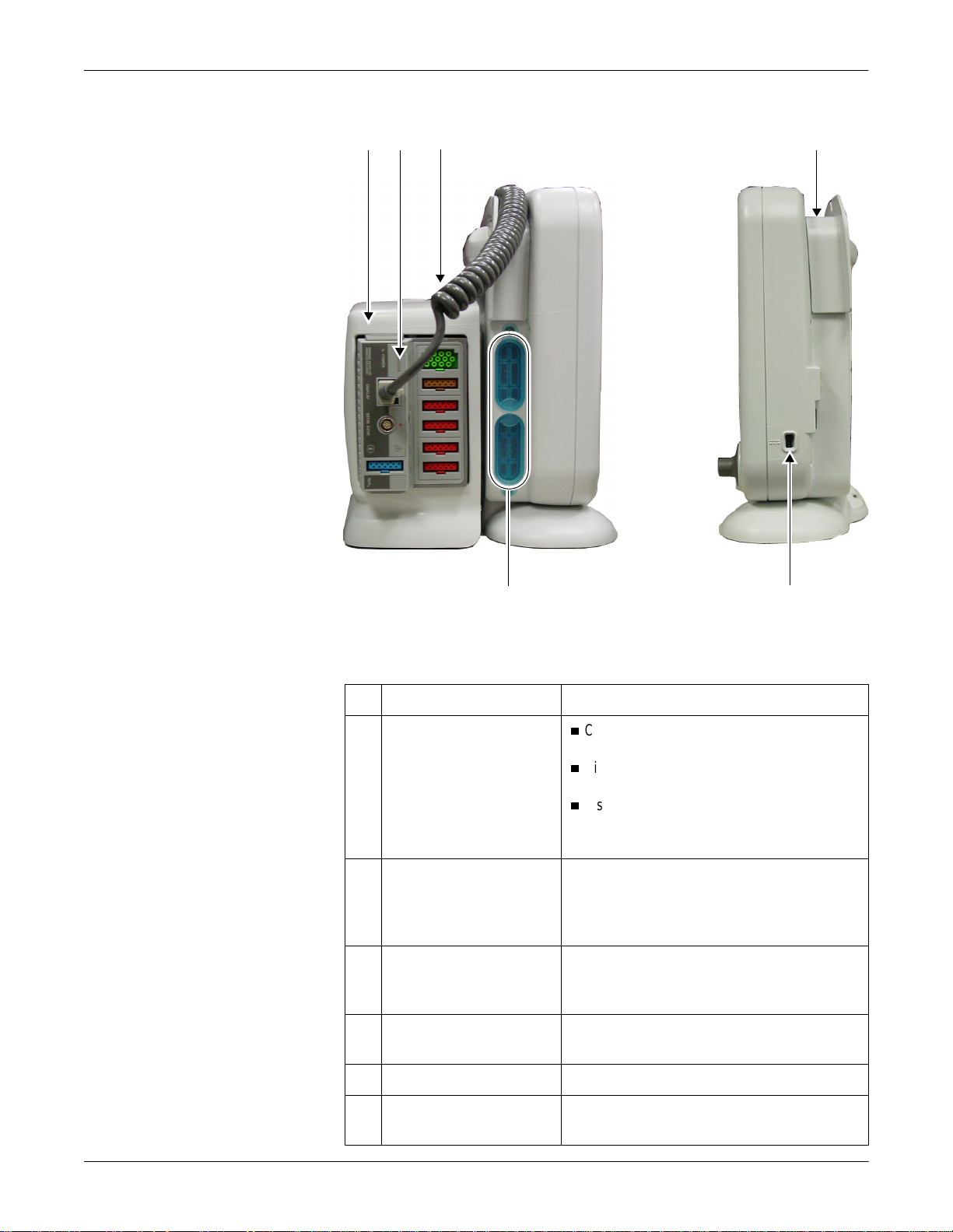
Side Views
Equipment Overview: Equipment Description
AB C D
841A, 842A
FE
Left Side Right Side
Name Description
A Tram chute
Connect the Tram chute to the display and insert
a Tram module to create a transport monitor.
Disconnect the Tram chute from the display to
use the display as a remote display.
Disconnect the Tram chute from the display to
allow for alternate or permanent mountings of
the transport monitor.
B Tram module Insert a Tram module into the Tram chute to create
a transport monitor. See “Tram Module
Compatibility” on page 2-10 for a listing of
compatible Tram modules.
C “Curly” data cable Connect to the Tram module and to the display.
The data cable provides communication between
the Tram module and the display.
D Data cable channel Place the Tram module data cable in the channel
to reduce cable clutter.
E DC power connector See “Connectors” on page3-8.
F Battery doors Open the battery doors to insert and remove the
batteries.
Revision A Transport Pro Patient Monitor 2-7
2012659-002
Controls
Trim Knob Control
Power Key
Equipment Overview: Equipment Description
The Trim Knob control is a 24-position rotary control with a push
selection switch.
127(
This key must be depressed for 0.25 seconds before the function is
activated. This helps prevent inadvertently turning the monitor off.
When the monitor is battery powered, this key turns the monitor
power on and off.
When the monitor is plugged into an elec trical outlet using the
optional power supply, or when it is powered by a Tram module
plugged into a powered Tram-rac housing, this key turns the
monitoring standby mode on and off.
When the standby mode is turned on, patient monitoring is
discontinued. How ever, patie nt data already accumulated is retained
and the battery charging function conti nues.
Function Keys
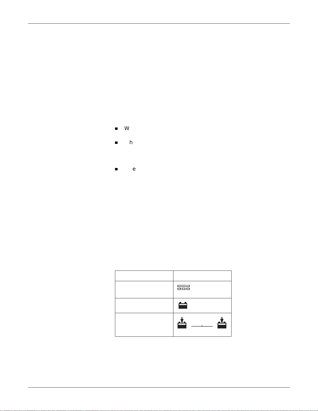
Indicators
Three fixed function ke ys are p r ovide d fo r NBP GO/STOP, ZERO ALL,
and SILENCE ALARM/ADMIT. See the Transport Pro Operator’s
Manual for a description.
Power and battery indicators are also located on the front panel of the
monitor.
Indicator Monitor Label
DC power
823A
Battery power
Battery charge
A
B
821A
127(
All four front panel indicators illuminate as the monitor powers up or
when the monitor changes between normal mode and standby mode.
2-8 Transport Pro Patient Monitor Revision A
2012659-002
DC Power Indicator
Battery Power Indicator
Charge Status Indicators
Equipment Overview: Equipment Description
The indicator illuminates green when the monitor is connected to an
electrical outlet using the optional external power supply (including
when the monitor is in the stan dby mode). The indicator does not
illuminate when the monitor is not plugged into an electrical outlet.
The indicator illuminates yellow when one of the following occurs.
The monitor is battery powered.
The monitor is powered by a Tram module plugged into a powered
Tram-rac housing.
The indicator is not illuminated when the monitor is not powered by
battery or by the optional external power supply.
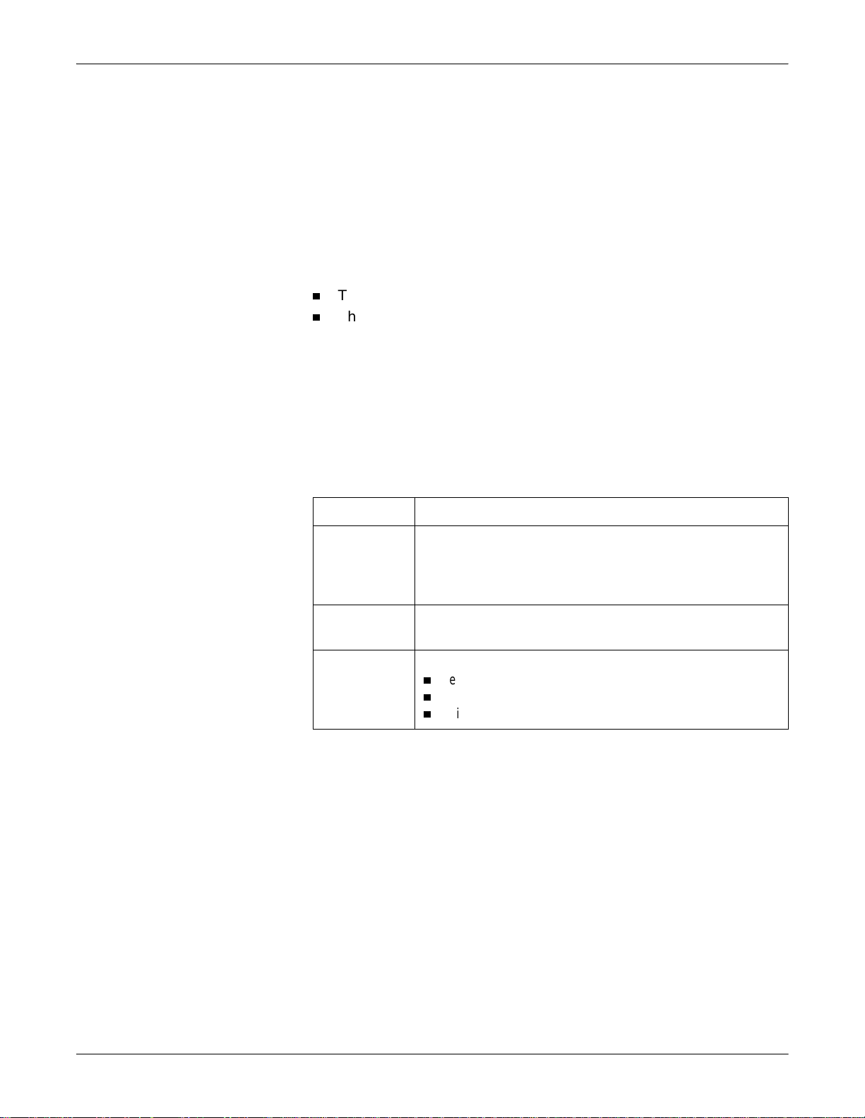
The following table explains what the Charging Status indicators mean.
“Battery In Use” Indicators
LED Color Explanation
Yellow Two battery icons, labeled Charging Status A and B, illuminate
yellow when the respective battery is being charged. If both batteries
are present and require charging, then both icons illuminate yellow
even though they charge sequentially.
Green The icon illuminates green when the respective battery is fully
charged.
No Light The icon does not illuminate under the following conditions:
The respective battery is not installed.
The monitor is operating on battery power.
A failure condition has been detected for the respective battery.
The “Battery In Use” indicator (inside the battery door) illuminates
green when the monitor is receiving power solely from the respective
battery. The indicators do not illuminate when the monitor is not battery
powered.
Neither indicator illuminates when the monitor is operating from both
batteries simultaneously (i.e., in a very low battery charge condition
when both batteries are joined together in order to sust ain operation of
the monitor).
Revision A Transport Pro Patient Monitor 2-9
2012659-002

Equipment Overview: Tram Module Compatibility
Tram Module Compatibility
The monitor is compatible with the following Tram modules.
127(
The Tram modules must use Tram software version 9B or later.
Device Part Number Description
Tram 100 401174-00x 3,5, or 10 lead ECG, Respiration, Cardiac Output or
Tram 200 A SL T200=A 3,5, or 10 lead ECG, Respiration, Cardiac Output or
Tram 250 A SL T250=A 3,5, or 10 lead ECG, Respiration, Cardiac Output or
Tram 350 A 404378-002 3,5, or 10 lead ECG, Respiration, Cardiac Output or
Dual temperature, 2 BP, NIBP
Dual temperature, 2 BP, NIBP, Ohmeda SpO2
Dual temperature, 2 BP, NIBP, Nellcor/ GEMS-IT
SpO2
Dual temperature, 4 BP, NBP, Nellcor/ GEMS-IT
SpO2
Tram 350 M 416646-001 3,5, or 10 lead ECG, Respiration, Cardiac Output or
Dual temperature, 4 BP, NBP, Masimo SpO2
Tram 400 A SL T400=A 3,5, or 10 lead ECG, Respiration, Cardiac Output or
Dual temperature, 3 BP, NIBP, Ohmeda SpO2
Tram 450 A SL T450=A 3,5, or 10 lead ECG, Respiration, Cardiac Output or
Dual temperature, 3 BP, NIBP, Nellcor/ GEMS-IT
SpO2
Tram 451 T451=X 3,5, or 10 lead ECG, Respiration, Cardiac Output or
Dual temperature, 3/4 BP, NIBP, GEMS-IT SpO2
Tram 451M T451M=X 3,5, or 10 lead ECG, Respiration, Cardiac Output or
Dual temperature,3/4 BP, NIBP, Masimo SET
SpO2
Tram 451N T451N=X 3,5, or 10 lead ECG, Respiration, Cardiac Output or
Dual temperature, 3 BP, NIBP, Nellcor
XL
SpO2
Tram 500 402593-00x 3,5, or 10 lead ECG, Respiration, Cardiac Output or
Dual temperature, 4 BP
Tram 600 A SL T600=A 3,5, or 10 lead ECG, Respiration, Cardiac Output or
Dual temperature, 4 BP, Ohmeda SpO2
Oxismart
Tram 650 A SL T650=A 3,5, or 10 lead ECG, Respiration, Cardiac Output or
Dual temperature, 4 BP, Nellcor/ GEMS-IT SpO2
Tram 800 A SL T800SL=A 3,5, or 10 lead ECG, Respiration, Cardiac Output or
Dual temperature, NIBP, Ohmeda/ GEMS-IT SpO2
Tram 850 A SL T850SL=A 3,5, or 10 lead ECG, Respiration, Cardiac Output or
Dual temperature, NIBP, Nellcor/ GEMS-IT SpO2
2-10 Transport Pro Patient Monitor Revision A
2012659-002

Equipment Overview: Tram Module Compatibility
Device Part Number Description
Tram 851 T851=X 3,5, or 10 lead ECG, Respiration, Cardiac Output or
Dual temperature, NIBP, GEMS-IT SpO2
Tram 851M T851M=X 3,5, or 10 lead ECG, Respiration, Cardiac Output or
Dual temperature, NIBP, Masimo SET
SpO2
Tram 851N T851N=X 3,5, or 10 lead ECG, Respiration, Cardiac Output or
Dual temperature, NIBP, Nellcor
Oxismart XL
SpO2
Revision A Transport Pro Patient Monitor 2-11
2012659-002
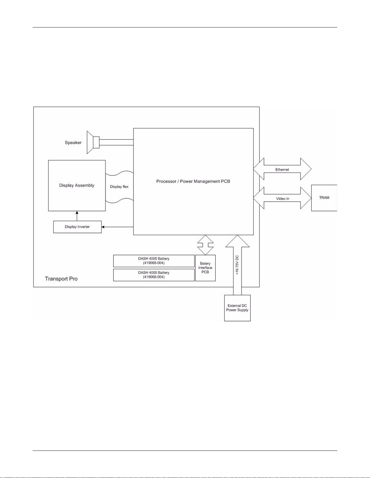
Equipment Overview: Theory of Operation
Theory of Operation
Block Diagram
The following theory of operation provides an overvi ew of the various
functional circuit boards in the monitor.
890A
Display Assembly
The display assembly consists of the flat-panel display and the main
control/indicator panel. (Additional indicators are contained in the
Processor/Power Management circuit board assembly.)
Power Supply
The subsystems within the display operate from a common 9 to 18V
power bus. Due to the wide variety of voltages required by the various
subsystems, power is converted locally by each subsystem . This
architecture results in an efficient and compact system by reducing the
number of conversions required and optimizing the physical size of each
converter for the specific application.
2-12 Transport Pro Patient Monitor Revision A
2012659-002

Equipment Overview: Theory of Operation
When operating on external power, the power bus voltage is 16.75V,
generated by the external power supply.
No external power switch is provided.
The line voltage range of the external power supply is 85V to 270V AC.
Processor/Power Management Circuit Board Assembly
The processor/power management circuit board assembly consists of the
processor/power management circuit board, LCD backlight inverter
circuit board, and speaker. These items are mounted in an open-ended
sheet metal box for additional EMI shielding.
Processor/Power Management Circuit Board
The processor/power manag ement circuit board provides processing
memory, user interface, communication channels, power and
rechargeable battery hardware functions for the monitor.
LCD Backlight Inverter Circuit Board
The LCD backlight inverter is a DC to AC inverter for a dual lamp LCD.
The input voltage is rated at +8V to +18V DC and the output voltage is
rated at 300 to 700 VRMS. The start voltage is 1400 VRMS and the lamp
current is 7 milliamps per tube.
Speaker
The speaker is used for aud ible notificat ion of alarms. It is 66mm square,
water-resistant, 3 watt, with a frequency response of 400Hz to 4500Hz.
Revision A Transport Pro Patient Monitor 2-13
2012659-002

For your notes
Equipment Overview: Theory of Operation
2-14 Transport Pro Patient Monitor Revision A
2012659-002

3 Installation
Revision A Transport Pro Patient Monitor 3-1
2012659-002

For your notes
3-2 Transport Pro Patient Monitor Revision A
2012659-002
 Loading...