

Page 1
Critical Power
User Manual
Uninterruptible Power Supply
GE Consumer & Industrial SA
General Electric Company
CH – 6595 Riazzino (Locarno)
Switzerland
T +41 (0)91 / 850 51 51
F +41 (0)91 / 850 52 52
www.gecriticalpower.com
imagination at work
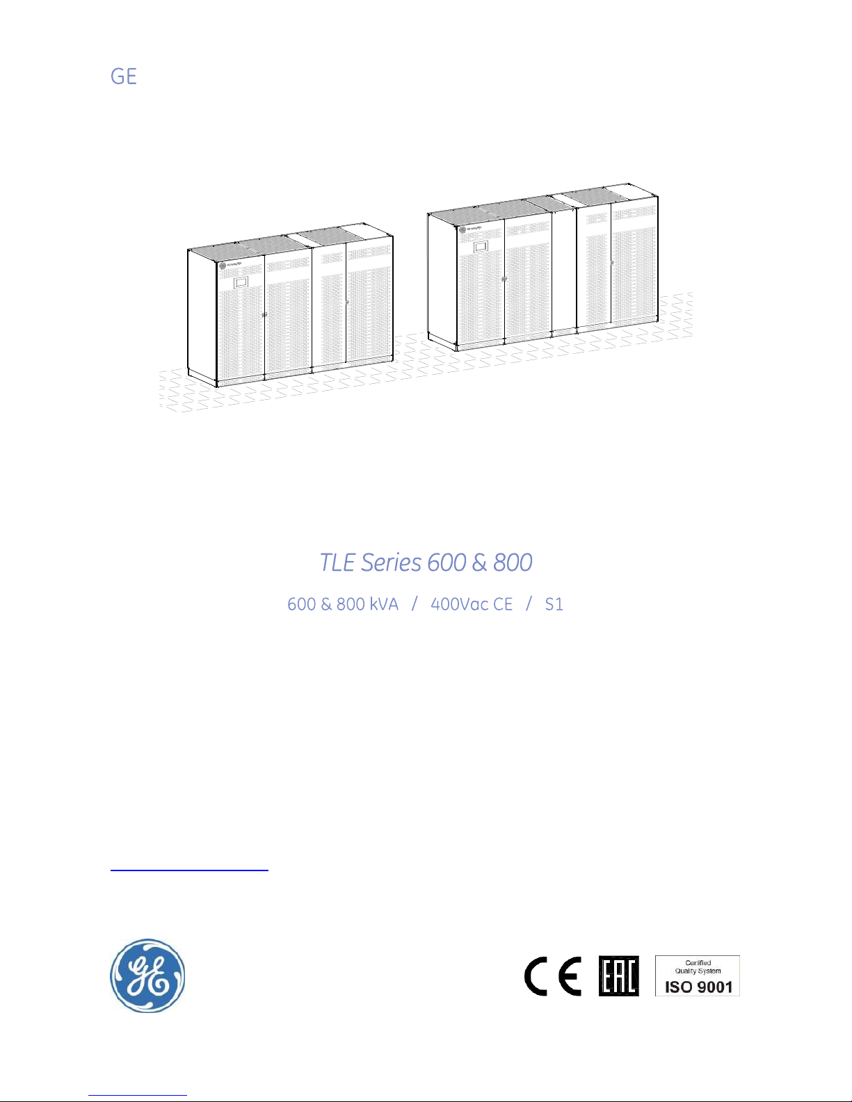
TLE Series 600
TLES_600-800_S1_UPS_GE_01
TLE Series 800
Page 2
Critical Power
Modifications reserved
Page 2/146
GE_UPS_OPM_TLE_SCE_M60_M80_1GB_V020.docx
User Manual TLE Series 600 & 800 CE S1
Model:
TLE Series 600 & 800 CE S1
Issued by:
Product Document Department – Riazzino - CH
Approved by:
R & D Department – Riazzino - CH
Date of issue:
20.01.2017
File name:
GE_UPS_OPM_TLE_SCE_M60_M80_1GB_V020
Revision:
2.0
Identification No.:
1030142
Up-dating
Revision
Concern
Date
2.0
ECN 2427 (Bypass fuses) and Safety rules for battery
20.01.2017
COPYRIGHT © 2017 by GE Consumer & Industrial SA
All rights reserved.
The information contained in this publication is intended solely for the purposes indicated.
The present publication and any other documentation supplied with the UPS system is not to be
reproduced, either in part or in its entirety, without the prior written consent of GE.
The illustrations and plans describing the equipment are intended as general reference only and are not
necessarily complete in every detail.
The content of this publication may be subject to modification without prior notice.
Page 3
Critical Power
Modifications reserved
Page 3/146
GE_UPS_OPM_TLE_SCE_M60_M80_1GB_V020.docx
User Manual TLE Series 600 & 800 CE S1
Dear Customer,
We thank you for selecting our products and are
pleased to count you amongst our very valued
customers at GE.
We trust that the use of the TLE Series 600 & 800
Uninterruptible Power Supply System, developed
and produced to the highest standards of
quality, will give you complete satisfaction.
Please carefully read the User Manual.
It contains all the necessary information about
the installation of the UPS.
Thank you for choosing GE !
Distributed by:
Your service contact:
g
GE Consumer & Industrial SA
General Electric Company
CH – 6595 Riazzino (Locarno)
Switzerland
Page 4
Critical Power
Modifications reserved
Page 4/146
GE_UPS_OPM_TLE_SCE_M60_M80_1GB_V020.docx
User Manual TLE Series 600 & 800 CE S1
Preface
Congratulations on your choice of a TLE Series 600 & 800 Uninterruptible Power Supply
(UPS).
It will keep you away from any trouble due to unexpected power problems.
This manual describes how to prepare the installation site, provides weight and dimensions
and procedures for moving, installing and connecting the UPS, and details of maintenance
procedures suggested to preserve maximum reliability.
It explains the function of the UPS module, the purpose and location of the switches, the
meaning of the system events related to the front panel indication, and provides
procedures for starting and stopping the equipment.
While every care has been taken to ensure the completeness and accuracy of this manual,
GE’s Critical Power assumes no responsibility or liability for any losses or damages resulting
from the use of the information contained in this document.
WARNING!
TLE Series 600 & 800 is a product for restricted sales distribution to informed partners.
Installation restrictions or additional measures may be needed to prevent disturbances.
We recommend that this manual is kept next to the UPS for future references.
If any problems are encountered with the procedures contained in this manual, please
contact your Service Centre before you proceed.
This document shall not be copied or reproduced without the permission of GE.
Due to technical improvements, some of the information contained in this manual may be
changed without notice.
Safety instructions
Carefully read the safety instructions contained on the following page before the
installation, start-up and maintenance of the UPS, options and battery.
Pay attention to the rectangular boxes included in the text:
They contain important information or warning concerning electrical connections and
personnel safety.
Parallel System secured with RPA
When included in the text, this symbol refers to operation
needed only For the RPA Parallel System.
Page 5

Critical Power
Modifications reserved
Page 5/146
GE_UPS_OPM_TLE_SCE_M60_M80_1GB_V020.docx
User Manual TLE Series 600 & 800 CE S1
Table of content Page
1 SAFETY RULES ................................................................................................................................................................... 7
1.1 SAFETY SYMBOLS AND WARNINGS ..................................................................................................................................................................... 9
2 LAYOUT .............................................................................................................................................................................10
2.1 LAYOUT TLE SERIES 600 ........................................................................................................................................................................................ 10
2.2 LAYOUT TLE SERIES 800 ........................................................................................................................................................................................ 12
3 INTRODUCTION ..............................................................................................................................................................14
4 DESCRIPTION ...................................................................................................................................................................15
4.1 BLOCK DIAGRAM AND MAIN ELEMENTS ........................................................................................................................................................ 16
4.2 OPERATION MODES ................................................................................................................................................................................................. 17
4.2.1 Normal VFI Operation Mode (Voltage Frequency Independent) ........................................................................................................................ 17
4.2.2 eBoost™ Operation Mode (option) .................................................................................................................................................................................... 17
4.2.3 Mains Failure Operation ......................................................................................................................................................................................................... 18
4.2.4 Mains Recovery Operation .................................................................................................................................................................................................... 18
4.2.5 Automatic Bypass...................................................................................................................................................................................................................... 19
4.3 RPA PARALLEL SYSTEM OPERATION ................................................................................................................................................................ 20
4.3.1 Introduction to the RPA Parallel System......................................................................................................................................................................... 20
4.3.2 Features of RPA Parallel System ........................................................................................................................................................................................ 21
4.3.3 System control ............................................................................................................................................................................................................................ 21
4.3.4 Synchronization .......................................................................................................................................................................................................................... 21
4.3.5 Load sharing ................................................................................................................................................................................................................................ 21
4.3.6 IEMi Operation Mode (option)............................................................................................................................................................................................... 22
4.4 UPS PARALLELED ON THE SAME BATTERY .................................................................................................................................................... 23
4.5 SERVICE AND TECHNICAL SUPPORT ................................................................................................................................................................ 24
4.6 WARRANTY .................................................................................................................................................................................................................. 24
4.7 RECYCLING AT THE END OF SERVICE LIFE ..................................................................................................................................................... 25
5 INSTALLATION .................................................................................................................................................................26
5.1 TRANSPORT................................................................................................................................................................................................................. 26
5.1.1 Dimensions and weights TLE Series 600 & 800 .......................................................................................................................................................... 27
5.2 DELIVERY ...................................................................................................................................................................................................................... 28
5.3 STORAGE ...................................................................................................................................................................................................................... 28
5.3.1 Storage of the UPS .................................................................................................................................................................................................................... 28
5.3.2 Storage of Battery ..................................................................................................................................................................................................................... 28
5.4 PLACE OF INSTALLATION ...................................................................................................................................................................................... 29
5.4.1 UPS location ................................................................................................................................................................................................................................. 29
5.4.2 Battery location .......................................................................................................................................................................................................................... 34
5.5 VENTILATION AND COOLING ............................................................................................................................................................................... 35
5.6 UNPACKING ................................................................................................................................................................................................................ 36
5.7 INTER CABINET CONNECTIONS .......................................................................................................................................................................... 38
5.7.1 Cabinets positioning and interconnection .................................................................................................................................................................... 38
5.7.2 Bus bars interconnection ....................................................................................................................................................................................................... 40
5.7.3 Control cables interconnection .......................................................................................................................................................................................... 42
5.8 ELECTRICAL WIRING ............................................................................................................................................................................................... 46
5.8.1 Mains input connection .......................................................................................................................................................................................................... 46
5.8.2 Input/output over current protection and wire sizing ............................................................................................................................................. 47
5.8.3 Installation requirements....................................................................................................................................................................................................... 49
5.9 ELECTRICAL CONNECTION ................................................................................................................................................................................... 51
5.9.1 TLE Series 600 - Power connection with Common Mains Input ......................................................................................................................... 55
5.9.2 TLE Series 600 - Power connection with Separate Mains Input ......................................................................................................................... 56
5.9.3 TLE Series 800 - Power connection with Common Mains Input ......................................................................................................................... 58
5.9.4 TLE Series 800 - Power connection with Separate Mains Input ......................................................................................................................... 59
5.9.5 Use of TLE Series 600 & 800 in eBoost™ Operation Mode .................................................................................................................................... 61
5.9.6 Use of TLE Series 600 & 800 as Frequency Converter ............................................................................................................................................ 62
5.10 RPA PARALLEL SYSTEM CONNECTION ............................................................................................................................................................ 63
5.10.1 Power wiring of parallel units .............................................................................................................................................................................................. 63
5.10.2 Parallel control bus connection .......................................................................................................................................................................................... 64
5.10.3 Control bus cable location .................................................................................................................................................................................................... 66
5.11 EPO COMMAND CONNECTION (EMERGENCY POWER OFF) ................................................................................................................... 68
6 CONTROL PANEL ............................................................................................................................................................70
6.1 CONTROL PANEL ...................................................................................................................................................................................................... 70
Page 6

Critical Power
Modifications reserved
Page 6/146
GE_UPS_OPM_TLE_SCE_M60_M80_1GB_V020.docx
User Manual TLE Series 600 & 800 CE S1
7 LCD SCREEN ....................................................................................................................................................................71
7.1 HOME SCREEN ........................................................................................................................................................................................................... 71
7.1.1 Description of the selection keys ....................................................................................................................................................................................... 72
7.1.2 Description of the signalling LEDs ..................................................................................................................................................................................... 73
7.2 MEASURES ................................................................................................................................................................................................................... 76
7.3 EVENTS ......................................................................................................................................................................................................................... 80
7.3.1 Events (alarms and messages) ........................................................................................................................................................................................... 82
7.3.2 Alarms list ...................................................................................................................................................................................................................................... 82
7.3.3 Messages list ................................................................................................................................................................................................................................ 87
7.4 SETUP ............................................................................................................................................................................................................................ 90
7.5 COMMANDS ................................................................................................................................................................................................................ 96
7.6 RPA PARALLEL SYSTEM ........................................................................................................................................................................................ 100
8 OPERATION ................................................................................................................................................................... 102
8.1 PROCEDURES FOR SINGLE TLE SERIES 600 & 800 ................................................................................................................................... 103
8.1.1 Initial start-up of the TLE Series 600 & 800 ................................................................................................................................................................. 103
8.1.2 Complete UPS shut-down ................................................................................................................................................................................................... 107
8.1.3 Restore to normal operation after “System shutdown” with Load not supplied ..................................................................................... 108
8.1.4 Restore to normal operation after “EPO - Emergency Power Off” with Load not supplied ................................................................ 110
8.2 PROCEDURES SINGLE TLE SERIES 600 & 800 FUNCTIONING AS FREQUENCY CONVERTER .................................................. 112
8.2.1 Initial Start-up of the TLE Series 600 & 800 as frequency converter ............................................................................................................. 112
8.2.2 Complete shut-down of the TLE Series 600 & 800 as frequency converter ............................................................................................... 116
8.2.3 Restore to normal operation after “System shutdown” with Load not supplied ..................................................................................... 117
8.2.4 Restore to normal operation after “EPO - Emergency Power Off” with Load not supplied ................................................................ 119
8.3 PROCEDURES FOR TLE SERIES 600 & 800 PARALLEL SYSTEM ............................................................................................................ 121
8.3.1 TLE Series 600 & 800 Parallel System start-up ......................................................................................................................................................... 121
8.3.2 Separate a UPS unit from the Redundant Parallel System ................................................................................................................................. 126
8.3.3 Reconnect a UPS unit to Redundant Parallel System ............................................................................................................................................ 128
8.3.4 Complete Parallel System shut-down ........................................................................................................................................................................... 130
8.3.5 Restore to normal operation after “System shutdown” with Load not supplied ..................................................................................... 131
8.3.6 Restore to normal operation after “EPO - Emergency Power Off” with Load not supplied ................................................................ 133
9 CUSTOMER INTERFACE ............................................................................................................................................... 135
9.1 SERIAL PORT J35µP - RS232 (SUB D, FEMALE 9 PIN)............................................................................................................................... 136
9.2 CUSTOMER INTERFACE BOARD ........................................................................................................................................................................ 137
9.2.1 Connector J1 – RJ45 8P8C .................................................................................................................................................................................................. 138
9.2.2 X1 terminal block - Output signals on voltage-free contacts ........................................................................................................................... 138
9.2.3 X1 terminal block - Programmable input free contacts ....................................................................................................................................... 138
9.2.4 X2 terminal block - EPO (Emergency Power Off) ...................................................................................................................................................... 139
9.2.5 X1 terminal block - Gen Set Signalling (GEN ON) ..................................................................................................................................................... 139
9.2.6 X1 terminal block - AUX external Maintenance Bypass ....................................................................................................................................... 140
9.2.7 X1 terminal block - eBoost/IEMi control signal ......................................................................................................................................................... 140
10 OPTIONS ........................................................................................................................................................................ 141
10.1 CONNECTIVITY OPTIONS ..................................................................................................................................................................................... 141
10.2 OPTIONS IN UPS CABINET .................................................................................................................................................................................. 142
11 MAINTENANCE ............................................................................................................................................................. 143
11.1 MAINTENANCE ........................................................................................................................................................................................................ 143
11.1.1 Service check ............................................................................................................................................................................................................................. 143
11.1.2 Fans and ventilation ............................................................................................................................................................................................................... 143
11.1.3 Other components with limited lifetime ....................................................................................................................................................................... 143
11.1.4 Battery ........................................................................................................................................................................................................................................... 144
11.1.5 UPS room conditions and temperature ........................................................................................................................................................................ 144
11.1.6 Preventive maintenance program .................................................................................................................................................................................. 144
12 NOTES ............................................................................................................................................................................ 145
12.1 NOTES FORM ............................................................................................................................................................................................................ 145
13 ANNEX ........................................................................................................................................................................... 146
13.1 TECHNICAL DATA SHEET ..................................................................................................................................................................................... 146
13.2 UPS SCHEMATIC DIAGRAMS .............................................................................................................................................................................. 146
13.3 CD-ROM ...................................................................................................................................................................................................................... 146
Page 7

Critical Power
Modifications reserved
Page 7/146
GE_UPS_OPM_TLE_SCE_M60_M80_1GB_V020.docx
User Manual TLE Series 600 & 800 CE S1
1 SAFETY RULES
Save these instructions!
GENERAL
- Move the UPS in an upright position in its original package to the final destination room.
To lift the cabinets, use a forklift or lifting belts with spreader bars.
- Check for sufficient floor and elevator loading capacity.
- Check the integrity of the UPS equipment carefully.
If you notice visible damage, do not install or start the UPS.
Contact the nearest Service Centre immediately.
- WARNING! RISK OF ELECTRICAL SHOCK:
Do not remove covers, there are no user serviceable parts inside.
- After switching off takes 5 minutes for the DC capacitors to discharge because a lethally high voltage
remains at the terminals of the electrolytic capacitors.
- UPS’s and battery system require a 12 months periodic maintenance to operate reliably and safely.
This should be performed by qualified service personnel.
The UPS contains its own energy source (battery).
- The field-wiring outlets may be electrically live, even when the UPS is disconnected from the mains.
- Dangerous voltages may be present during battery operation.
- The battery must be disconnected during maintenance or service work.
- This UPS contains potentially hazardous voltages.
- Be aware that the inverter can restart automatically after the mains voltage is restored.
- End user must follow applicable regional occupational safety codes/regulations during installation,
operation and equipment maintenance. This may require additional field marking or labelling defining
appropriate level of PPE (Personal Protection Equipment) to reduce the risk of Arc-flash related injuries.
Contact our Technical Support for product specific information.
INSTALLATION
- This UPS must be installed and connected only by trained personnel.
- Verify accurately during Commissioning and Maintenance of the UPS, for the following:
Damaged components, squeezed wires and cables, or not correctly inserted plugs.
- After removing the sidewalls of the UPS, make sure that all earth connections when reassembling, are
correctly reattached.
- This UPS is intended for use in a controlled indoor environment free of conductive contaminants and
protected against animals intrusion.
- WARNING! HIGH EARTH LEAKAGE CURRENT:
Earth connection is essential before connecting to AC input!
- Switching OFF the unit does not isolate the UPS from the mains.
- Do not install the UPS in an excessively humid environment or near water.
- Avoid spilling liquids on or dropping any foreign object into the UPS.
- The unit must be placed in a sufficiently ventilated area; the ambient temperature should not exceed 40°C
(104°F).
- Optimal battery life is obtained if the ambient temperature does not exceed 25C (77°F).
- It is important that air can move freely around and through the unit. Do not block the air vents.
- Avoid locations in direct sunlight or near heat sources.
STORAGE
- Store the UPS in a dry location; storage temperature must be within -25°C (-13°F) to +55C (131°F).
- The optimal temperature for Battery storage is 20°C (68°F) to 25°C (77°F) and shall never exceed the range 20°C (-4°F) to 40°C (104°F).
- If the unit is stored for a period exceeding 3 months, the battery must be recharged periodically (time
depending on storage temperature).
BATTERY
- The battery-voltage is dangerous for person’s safety.
- When replacing the battery, use the same number, voltage (V) and capacity (Ah).
- Proper disposal or recycling of the battery is required.
Refer to your local codes for disposal requirements.
- Never dispose of battery in a fire: they may explode.
- Do not open or mutilate battery: their contents (electrolyte) may be extremely toxic.
If exposed to electrolyte, wash immediately with plenty of water.
- Avoid charging in a sealed container.
- Never short-circuit the batteries.
When working with batteries, remove watches, rings or other metal objects, and only use insulated tools.
Page 8
Critical Power
Modifications reserved
Page 8/146
GE_UPS_OPM_TLE_SCE_M60_M80_1GB_V020.docx
User Manual TLE Series 600 & 800 CE S1
Safety instructions when working with battery
EXTERNAL BATTERY MUST BE INSTALLED AND CONNECTED TO THE UPS BY
QUALIFIED SERVICE PERSONNEL.
INSTALLATION PERSONNEL MUST READ THIS ENTIRE SECTION BEFORE HANDLING
THE UPS AND BATTERY.
DANGER!
Full voltage and current are always present at the battery terminals.
The battery used in this system can provide dangerous voltages, extremely high currents and a risk
of electric shock.
If the terminals are shorted together or to ground they may cause severe injury.
You must be extremely careful to avoid electric shock and burns caused by contacting battery
terminals or shorting terminals during battery installation.
Do not touch uninsulated battery terminals.
A qualified service person, who is familiar with battery systems and required precautions, must
install and service the battery.
The installation must conform to national and local codes.
Keep unauthorised personnel away from the battery.
The qualified service person must take these precautions:
1 Wear protective clothing, such as rubber gloves and boots and protective eye wear.
Batteries contain caustic acids and toxic materials and can rupture or leak if mistreated.
Remove rings and metal wristwatches or other metal objects and jewellery.
Do not carry metal objects in your pockets where the objects can fall into the battery cabinet.
High energy through conductive materials could cause severe burns.
2 Tools must have insulated handles and must be insulated so that they will not short battery
terminals.
Do not allow a tool to short between individual or separate battery terminals or to the cabinet
or rack.
Do not lay tools or metal parts on top of the battery, and do not lay them where they could fall
onto the battery or into the cabinet.
3 Disconnect charging source prior to connecting or disconnecting battery terminals.
Install the battery as shown on the drawing provided with the battery.
When connecting cables, never allow a cable to short across a battery’s terminals, the string of
battery, or to the cabinet or rack.
4 Align the cables on the battery terminals so that the cable lug will not contact any part of the
cabinet or rack, even if the battery is moved.
Keep the cable away from any sharp metal edges.
5 Install the battery cables in such a way that the UPS or battery cabinet doors cannot pinch them.
6 Do not connect the battery terminal to Ground.
If any battery terminal is inadvertently grounded, remove the source of the ground.
Contacting any part of a grounded battery can cause a risk of electric shock.
7 Determine if battery is inadvertently grounded. If inadvertently grounded, remove source from
ground. Contact with any part of a grounded battery can result in electrical shock.
The likelihood of such shock can be reduced if such grounds are removed during installation and
maintenance.
8 To reduce the risk of fire or electric shock, install the battery in a temperature and humidity
controlled indoor area, free of contaminants.
9 Battery system chassis ground (earth) must be connected to the UPS chassis ground (earth).
If you use conduits, this ground conductor must be routed in the same conduit as the battery
conductors.
10 Where conductors may be exposed to physical damage, protect the conductors in accordance
with all applicable codes.
11 If you are replacing the battery or repairing battery connections, shut OFF the UPS and remove
the battery fuses.
Page 9
Critical Power
Modifications reserved
Page 9/146
GE_UPS_OPM_TLE_SCE_M60_M80_1GB_V020.docx
User Manual TLE Series 600 & 800 CE S1
SAFETY SYMBOLS AND WARNINGS
Safety warnings
The text of this manual contains some warnings to avoid risk to the persons and to avoid damages to
the UPS system and the supplied critical Loads.
The non-observance of the warnings reminding hazardous situations could result in human injury and
equipment damages.
Please pay attention to the meaning of the following warnings and symbols:
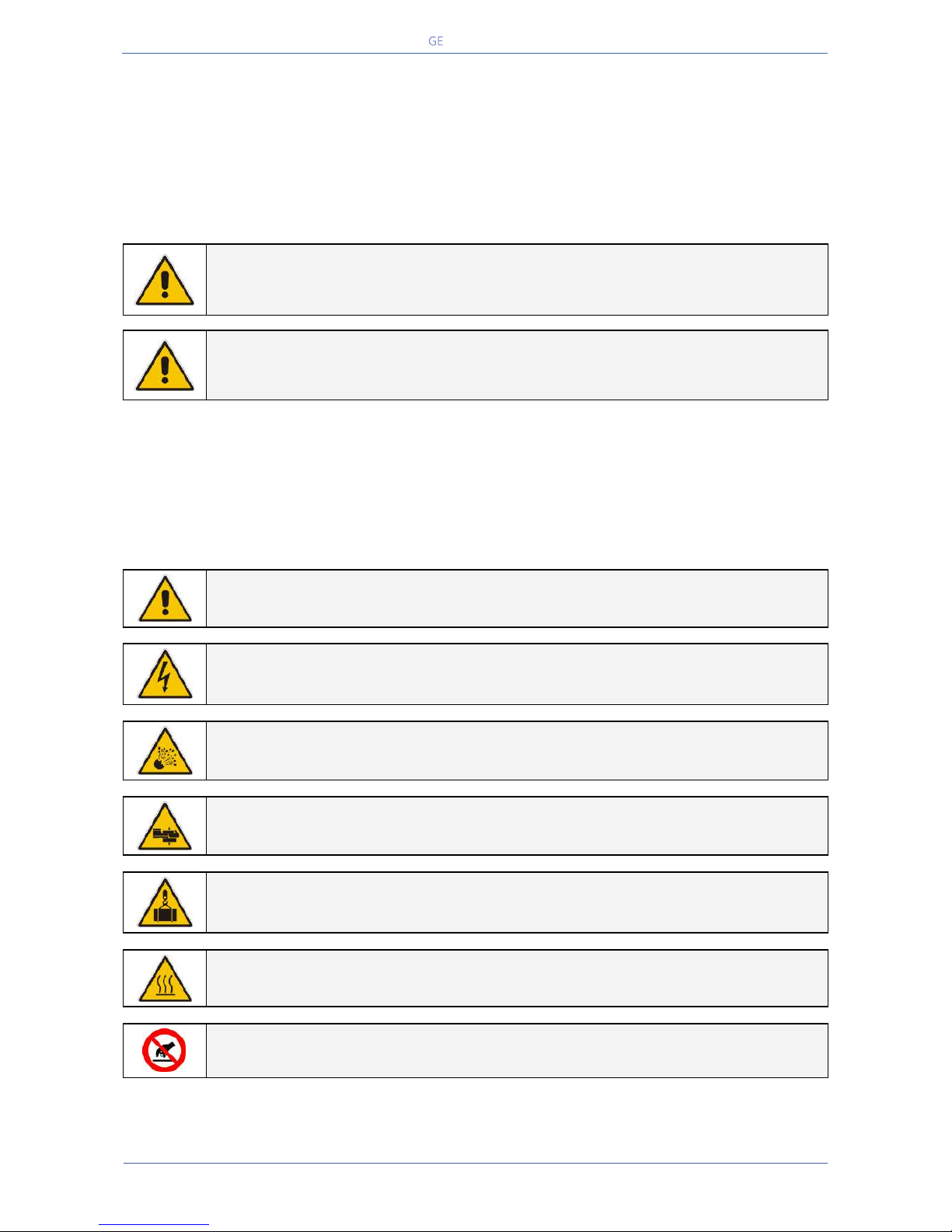
WARNING !
Referred to procedures or operations which could cause damages to the persons or
to the system, when not correctly operated.
NOTE !
Warns the user about important operations or procedures described in this manual.
Safety symbols
When the text includes one or more of the following symbols, that means exist a potentially hazardous
situations.
Please remind the meaning of each symbol.
CAUTION
Related to all the potentially hazardous situations which may result in injury.
DANGER OF PARTS ELECTRICALLY LIVE
Related to all the situation with potentially hazardous voltage.
DANGER OF EXPLOSION
Used to indicate conditions where exploding parts can cause serious injury.
DANGER OF CRUSHING
Used when moving the equipment due to the heavy weight.
DANGER OF OVERHUNG LOAD
Used when the equipment is lifted by a crane.
DANGER OF HOT SURFACE
Used to indicate conditions of elevated temperature on some parts.
DO NOT TOUCH
Risk of parts with hazardous voltages or parts in movement.
Page 10
Critical Power
Modifications reserved
Page 10/146
GE_UPS_OPM_TLE_SCE_M60_M80_1GB_V020.docx
User Manual TLE Series 600 & 800 CE S1
2 LAYOUT
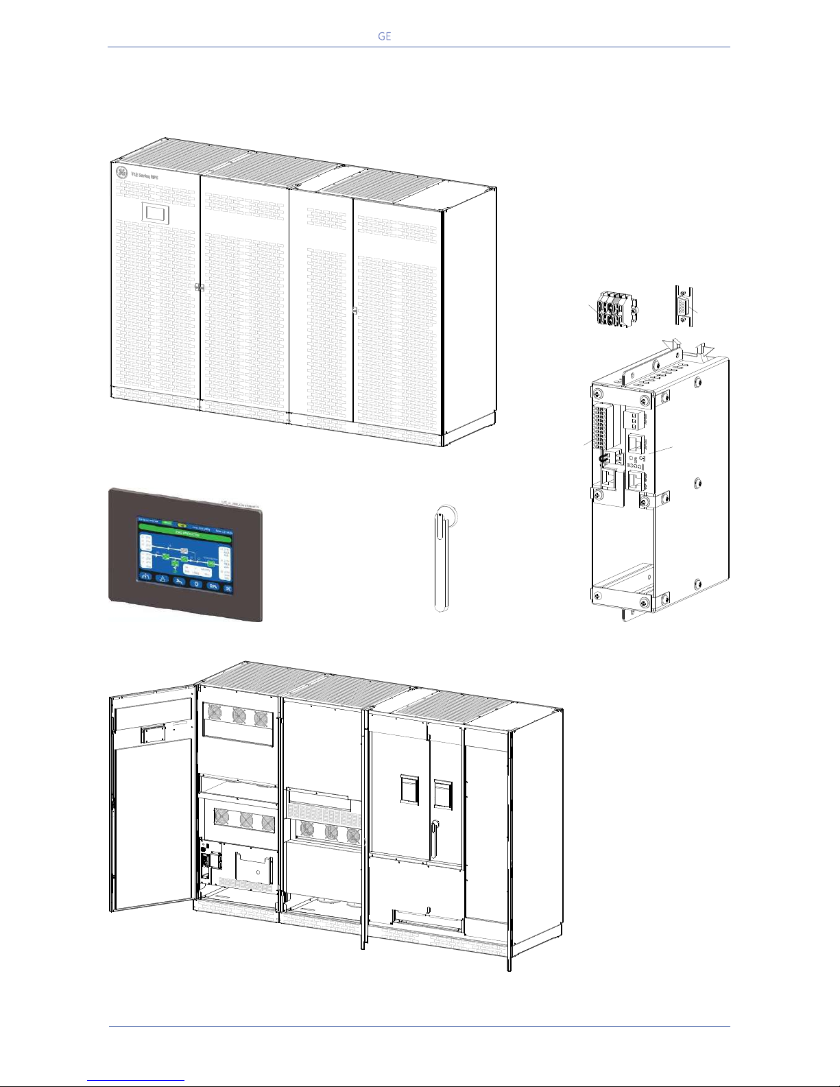
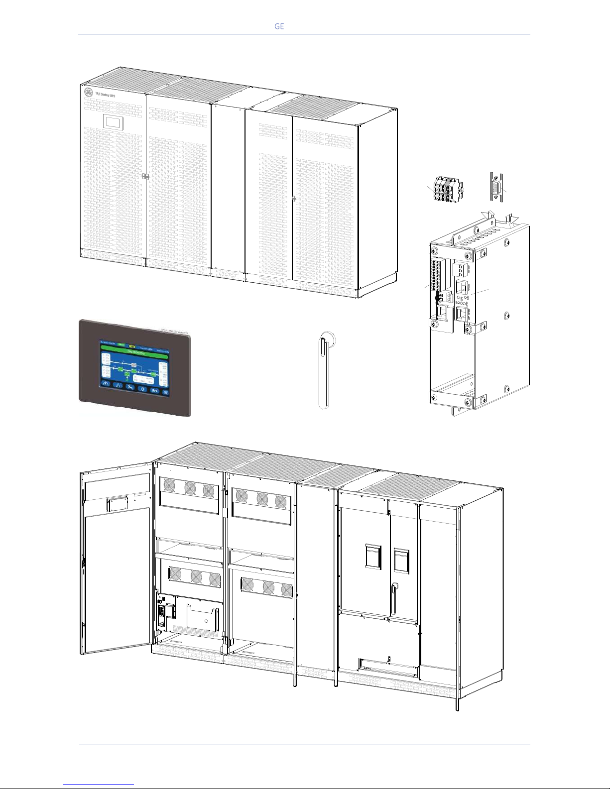
2.1 LAYOUT TLE SERIES 600
Fig. 2.1-1 TLE Series 600 - General view
l
Fig. 2.1-4 Connectivity Rack
Fig. 2.1-3 Control panel
Fig. 2.1-5 Manual switch “Q1 – UPS Output”
Fig. 2.1-2 TLE Series 600 - General view with open doors
TLES_UL_7500_S1_UPS_GE_02
SNMP
CI
EPO
EPO
-
+
J35µP
XA
1 2
TLES_160-400_S1_Customer interface-CI_SNMP_XA_01
TLES_UL_1000_S1_Switch Q1_01
Q1
0 OFF
I ON
TLES_UL_750_S1_UPS_GE_03
EPO
EPO
-
+
12
Q1
0 OFF
I ON
Page 11
Critical Power
Modifications reserved
Page 11/146
GE_UPS_OPM_TLE_SCE_M60_M80_1GB_V020.docx
User Manual TLE Series 600 & 800 CE S1
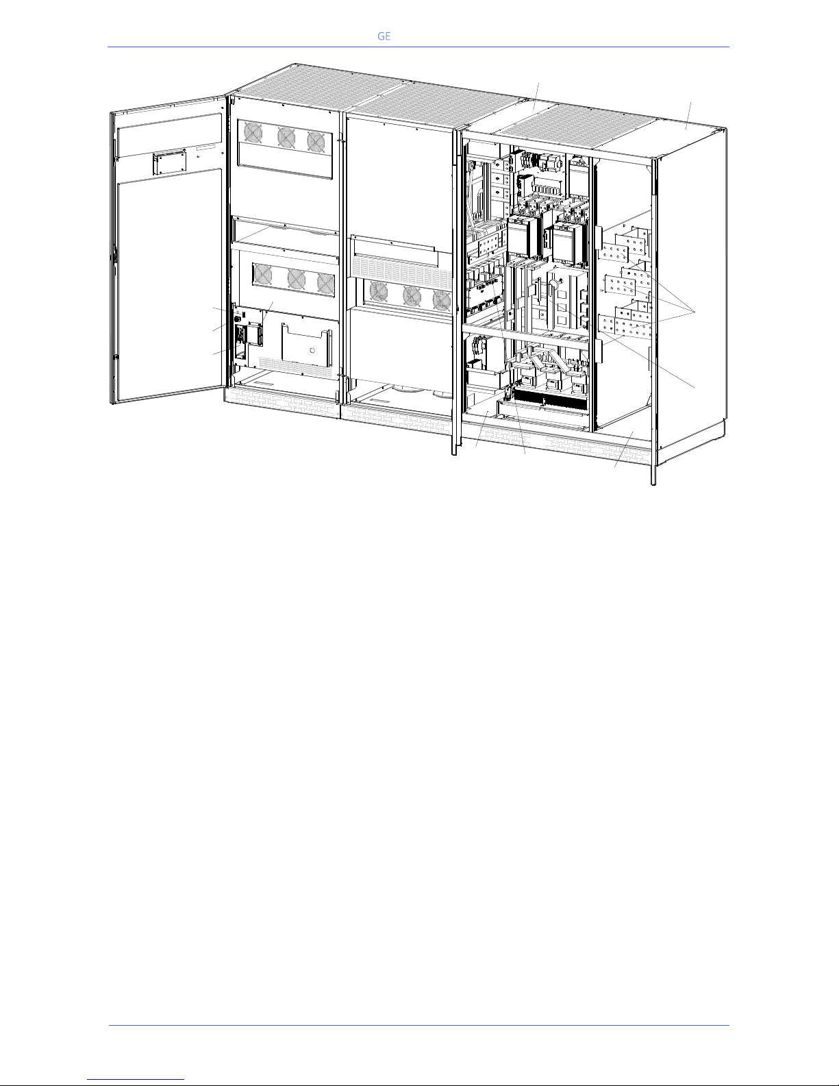
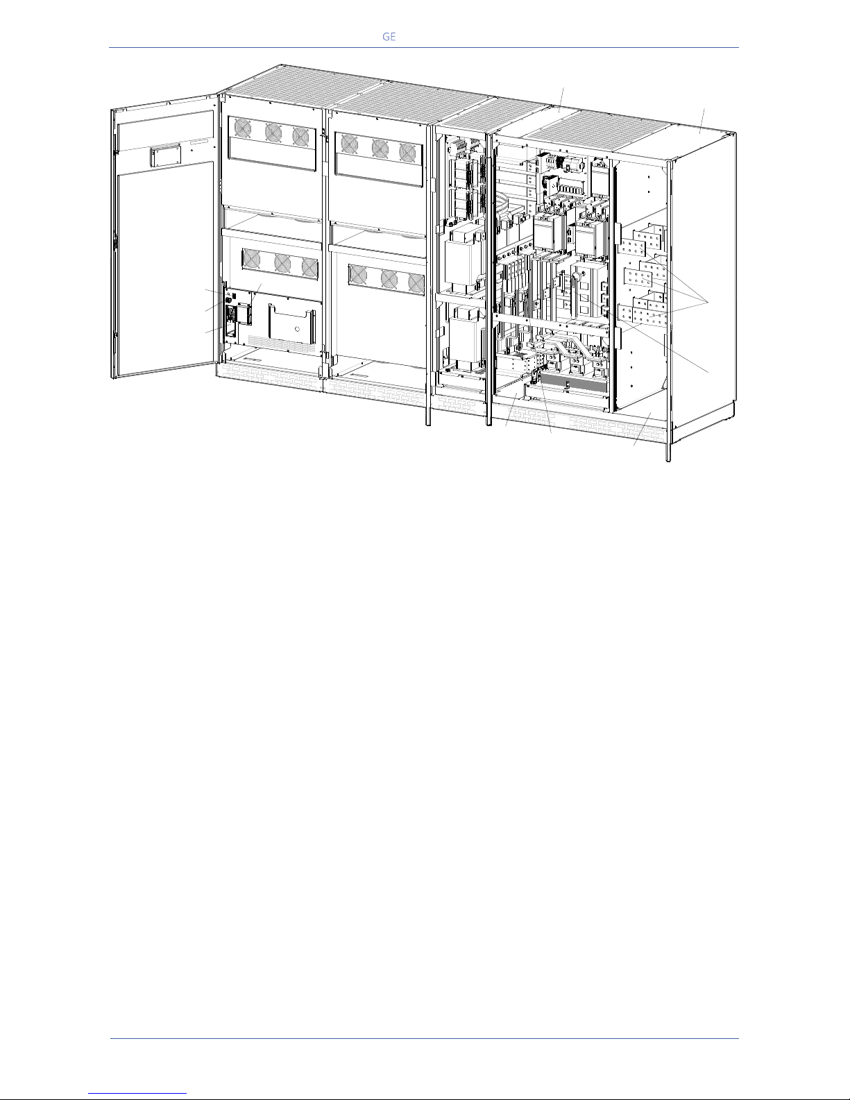
Fig. 2.1-6 TLE Series 600 - General view without protection panels
1a Top opening for input and output of connecting cables
(for Mains input and Load output connection)
1b Top opening for input and output of connecting cables
(for External Battery connection)
2a Bottom opening for input and output of connecting cables
(for Mains input and Load output connection)
2b Bottom opening for input and output of connecting cables
(for External Battery connection)
3 Bus bars for Mains input and Load output
4 Bus bars for External Battery connection
CI Customer Interface Board (see Fig. 2.1-4)
CR Connectivity Rack
J35µP Serial port RS232 for IMV protocol
Q1 UPS Output switch
RPA RPA board (Redundant Parallel Architecture) for Parallel System (option)
SNMP 3-ph SNMP/WEB plug-in adapter (option - see Fig. 2.1-4)
XA Terminals for “EPO - Emergency Power Off” connection and 24Vdc for external battery switch
TLES_UL_750_S1_UPS_GE_04
EPO
EPO
-
+
12
XA
CR
RPA
J35µP
3
2a
1b
1a
4
2b
Q1
Q1
Page 12
Critical Power
Modifications reserved
Page 12/146
GE_UPS_OPM_TLE_SCE_M60_M80_1GB_V020.docx
User Manual TLE Series 600 & 800 CE S1
2.2 LAYOUT TLE SERIES 800
Fig. 2.2-1 TLE Series 800 - General view
l
Fig. 2.2-4 Connectivity Rack
Fig. 2.2-3 Control panel
Fig. 2.2-5 Manual switch “Q1 – UPS Output”
Fig. 2.2-2 TLE Series 800 - General view with open doors
TLES_800_S1_UPS_GE_02
SNMP
CI
EPO
EPO
-
+
J35µP
XA
1 2
TLES_160-400_S1_Customer interface-CI_SNMP_XA_01
TLES_UL_1000_S1_Switch Q1_01
Q1
0 OFF
I ON
TLES_800_S1_UPS_GE_03
EPO
EPO
-
+
12
Q1
0 OFF
I ON
Page 13
Critical Power
Modifications reserved
Page 13/146
GE_UPS_OPM_TLE_SCE_M60_M80_1GB_V020.docx
User Manual TLE Series 600 & 800 CE S1
Fig. 2.2-6 TLE Series 800 - General view without protection panels
1a Top opening for input and output of connecting cables
(for Mains input and Load output connection)
1b Top opening for input and output of connecting cables
(for External Battery connection)
2a Bottom opening for input and output of connecting cables
(for Mains input and Load output connection)
2b Bottom opening for input and output of connecting cables
(for External Battery connection)
3 Bus bars for Mains input and Load output
4 Bus bars for External Battery connection
CI Customer Interface Board (see Fig. 2.2-4)
CR Connectivity Rack
J35µP Serial port RS232 for IMV protocol
Q1 UPS Output switch
RPA RPA board (Redundant Parallel Architecture) for Parallel System (option)
SNMP 3-ph SNMP/WEB plug-in adapter (option - see Fig. 2.2-4)
XA Terminals for “EPO - Emergency Power Off” connection and 24Vdc for external battery switch
TLES_800_S1_UPS_GE_04
EPO
EPO
-
+
12
XA
CR
RPA
J35µP
3
2a
1b
1a
4
2b
Q1
Page 14
Critical Power
Modifications reserved
Page 14/146
GE_UPS_OPM_TLE_SCE_M60_M80_1GB_V020.docx
User Manual TLE Series 600 & 800 CE S1
3 INTRODUCTION
The TLE Series 600 & 800 Uninterruptible Power Supply (UPS) provides the energy supply for critical
loads which need a reliable, continuous free from voltage disturbances and frequency fluctuations
supply.
In case the power provided by the Mains Fails, or exceeds the permitted tolerances, the power to supply
the Load is provided by the Battery for the specified time at the rated Load (or longer at a reduced Load)
or until the Mains power returns.
TLE Series 600 & 800 is a truly VFI double conversion Uninterruptible Power Supply
(UPS), equipped with automatic bypass, where the load is normally supplied by the
inverter.
TLE Series 600 & 800 can be configured, if chosen, for the eBoost™ Operation Mode
(Option - High efficiency: up to 99% / Fast power transfer: <2ms) permitting
maximum energy saving.
If the Inverter is not able to supply the required Output Voltage, or when overload or
short-circuit on the output occur, the Load is instantly transferred to the Mains via
the Automatic Bypass.
The UPS automatically returns to normal mode when the failure condition is
restored.
KEY FEATURES:
More Critical equipment supported
Rated at 1 Power Factor, TLE Series 600 & 800 delivers more real power than other UPS in the market.
With today’s trend toward power factor corrected loads, TLE Series 600 & 800 can support more total
Load than any other UPS available, allowing you to support a greater number of today’s enterprise
computing Power Factor Corrected (PFC) equipment.
High Efficiency
Thanks to type Advanced Neutral Point Clamped three level IGBT technology, TLE Series 600 & 800
guarantees a high overall performance.
Intelligent Energy Management (IEM) combined with RPA, results in the most cost efficient and reliable
UPS solution in the industry.
Fully digital
Digital Signal Processor (DSP), Flash memory and Advanced Neutral Point Clamped are the technology
corner stones of a new age of power quality and power reliability.
RPA™ - Redundant Parallel Architecture™ Parallel System
GE’s Critical Power provides a unique technology called Redundant Parallel Architecture™ (RPA™) that
can parallel Uninterruptible Power Supply (UPS) modules with true redundancy.
With RPA™, there is no need for external electronics or switches to control the UPS modules in the
parallel system.
One of the UPS modules in the system arbitrarily takes a leadership role, while the other UPS modules
have access to all control parameters.
If one UPS fails to operate, the load is automatically redistributed among the others.
If the lead UPS fails to operate then a different UPS automatically takes on the leadership role.
The RPA™ systems are designed to have no single points of failure, ensuring the highest level of power
protection for critical loads.
Extremely flexible
Tailor made power protection to meet your individual installation requirements; TLE Series 600 & 800
offers various options like EMC filter and our comprehensive software for mission control and data
protection to cover all your application needs.
Page 15
Critical Power
Modifications reserved
Page 15/146
GE_UPS_OPM_TLE_SCE_M60_M80_1GB_V020.docx
User Manual TLE Series 600 & 800 CE S1
4 DESCRIPTION
TLE Series 600 & 800 is one of the best
performing and most reliable threephase UPS systems providing critical
power protection for a wide range of
applications.
Every TLE Series 600 & 800 system operates in VFI mode (Voltage Frequency Independent) yielding the
maximum levels of power reliability for all mission-critical processes.
With proven technology the TLE Series 600 & 800 UPS provides top class reliability and performance.
With backfeed protection and compliance to EMC standards the TLE Series 600 & 800 complies to
current and future standards.
Reliability can be further increased by paralleling up to six UPS units utilising GE’s unique RPA™
technology (Redundant Parallel Architecture).
With RPA every UPS is controlled in a true peer-to-peer configuration with redundancy in all critical
elements and functions, eliminating all single points of failure.
The decentralised bypass offers great flexibility to up or down grade the system in case future needs
might change.
TLE Series 600 & 800, BEST IN CLASS EFFICIENCY
High efficiency in double conversion mode up to 96.5% and eBoost™ operation mode up to 99%.
High efficiency at partial and reduced loads for cost benefits in operating conditions.
Higher efficiency at partial load in RPA Systems with adaptive capacity control (IEMi Operation Mode -
option).
TLE Series 600 & 800 products designed in compliance with IEC 62040-2 standard, C3 level for
immunity, i.e. can withstand possible disturbances and noise without affecting standard operating
conditions.
Advanced User Interface with touch screen display guided menu.
Reduced energy consumption costs.
Reduced size and costs of the air conditioning system.
Compact design, saving installation space.
NOTE !
Through their complete life cycle, all GE’s Critical Power UPS systems are fully
supported by service teams which provide world-class, 24x7 preventive and
corrective services, training and application expertise.
TLE Series 600
TLES_600-800_S1_UPS_GE_01
TLE Series 800
Page 16
Critical Power
Modifications reserved
Page 16/146
GE_UPS_OPM_TLE_SCE_M60_M80_1GB_V020.docx
User Manual TLE Series 600 & 800 CE S1
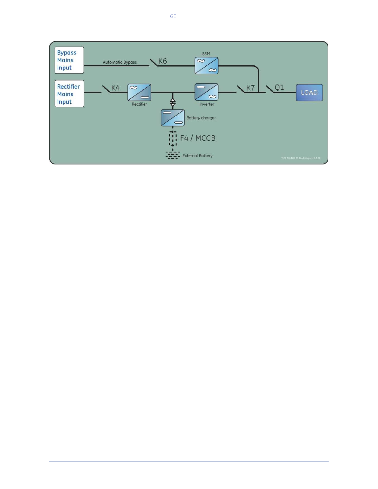
4.1 BLOCK DIAGRAM AND MAIN ELEMENTS
Fig. 4.1-1 TLE Series 600 & 800 - Block Diagram
The TLE Series 600 & 800 system can be divided into the following main elements:
Control System
TLE Series 600 & 800 is designed with microprocessor-controlled signal processing circuits.
The interface between the operator and the unit is provided by the monitoring system on the front
panel.
This monitoring system consists of an active mimic diagram, a keyboard and a backlit display.
Rectifier
The Active IGBT Rectifier converts the 3-phase mains voltage into a controlled and regulated DC-voltage,
supplying the inverter and to charge the battery through the battery-charger.
Thanks to modulation strategy applied to IGBT bridge, the rectifier provides clean input power in terms
of low THDi and unity power factor.
Inverter
The Inverter converts the DC voltage into a three-phase AC-voltage with constant amplitude and
frequency, which is completely independent and isolated from the AC-input voltage.
Automatic Bypass
The Automatic Bypass consists of a static semiconductor-switch (SSM: Static Switch Module), used to
provide an uninterrupted transfer of the Load from Inverter to Mains.
Back-feed Protection
All TLE Series 600 & 800 UPS's are equipped with an automatic system for the protection against voltage
back feeding towards Mains, through the Bypass (Applied Standard IEC 62040-1).
This protection works automatically by opening contactor K6 (in series with the thyristors of the static
switch) and eventually K7, and acts in case of internal defects of the system.
Battery
The Battery supplies the DC power to the Inverter when the Mains is out of acceptable tolerances.
Page 17
Critical Power
Modifications reserved
Page 17/146
GE_UPS_OPM_TLE_SCE_M60_M80_1GB_V020.docx
User Manual TLE Series 600 & 800 CE S1
4.2 OPERATION MODES
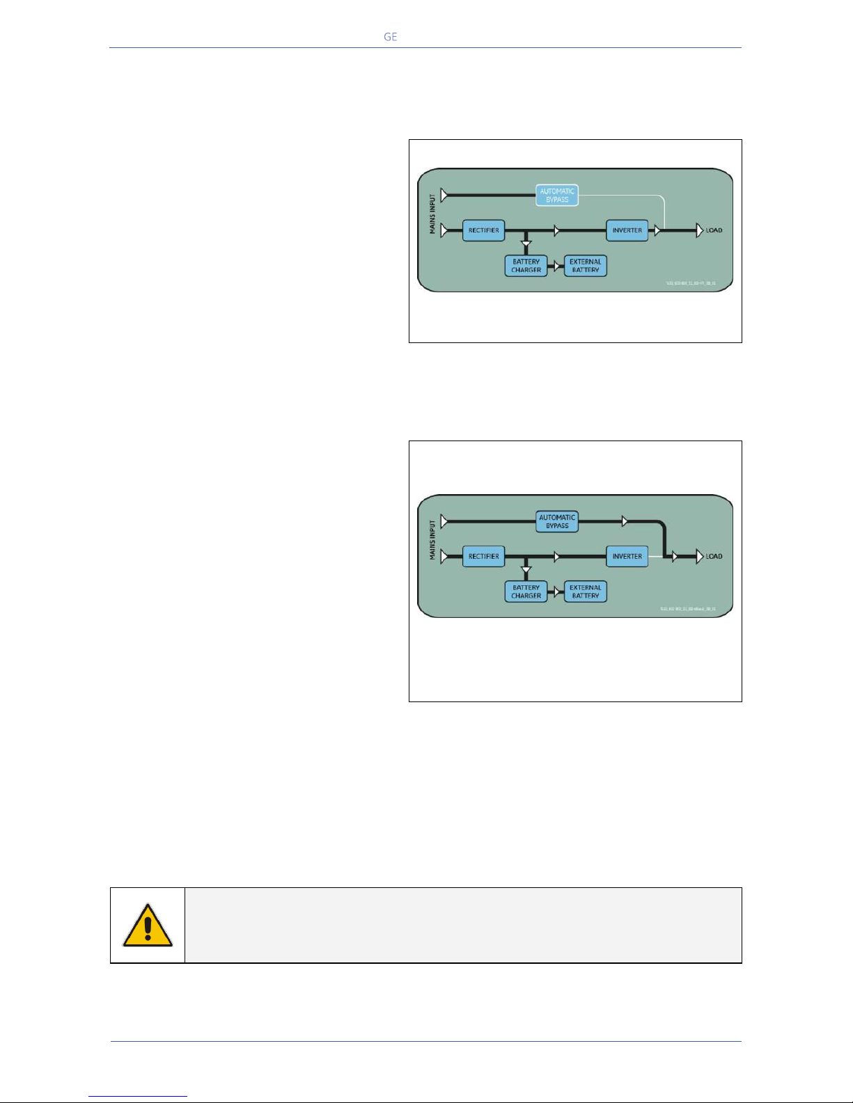
4.2.1 Normal VFI Operation Mode (Voltage Frequency Independent)
Under normal conditions the Load is
permanently powered by the inverter with
constant amplitude and frequency.
The Rectifier, powered by the Mains, supplies
the inverter and the battery-charger keeps the
battery fully charged.
The inverter converts the DC voltage in a new
AC sine wave voltage with constant amplitude
and frequency independently from the input
Mains Power.
Fig. 4.2.1-1 Block diagram normal VFI operation mode
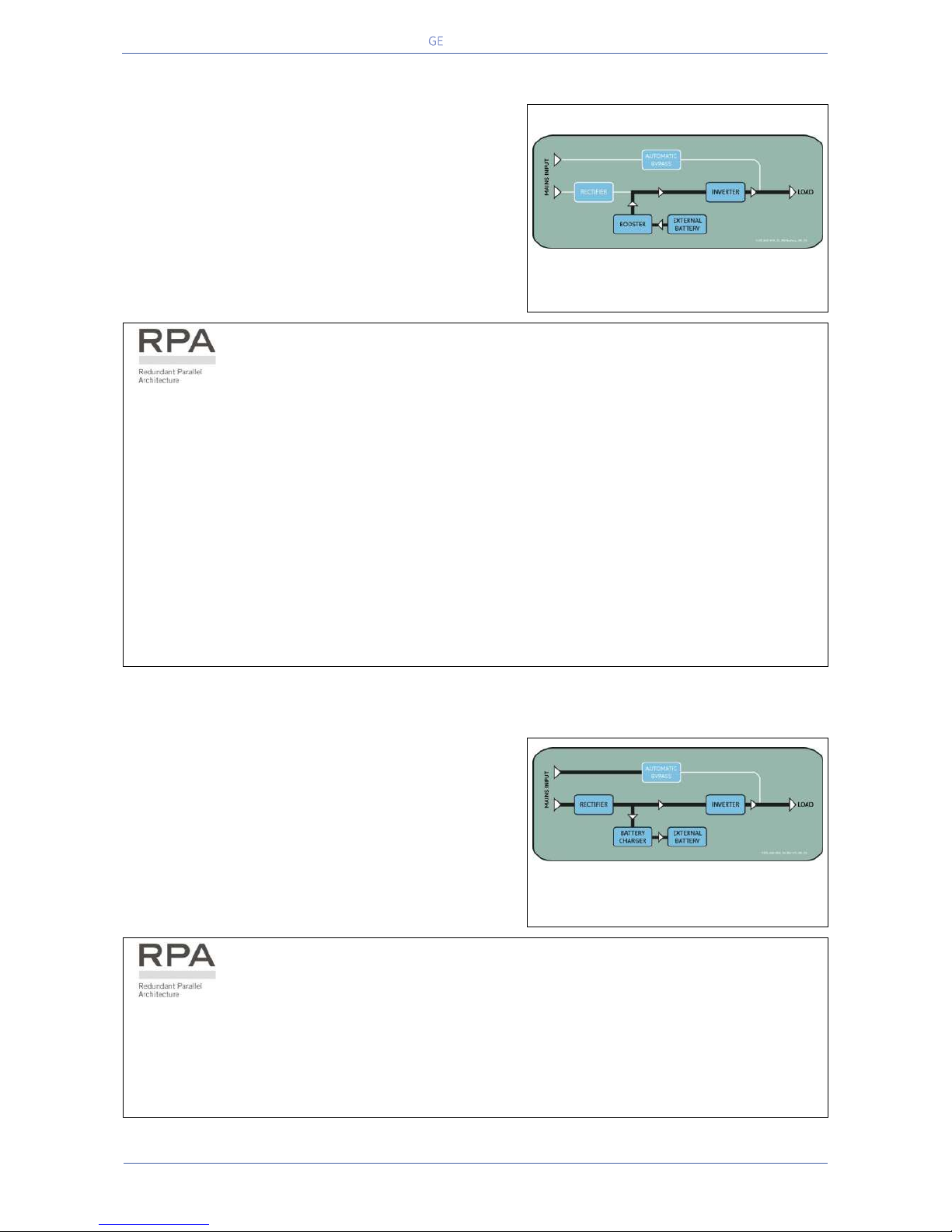
4.2.2 eBoost™ Operation Mode (option)
eBoost™
e High efficiency (up to 99%)
Boost Fast power transfer (< 2ms)
When the eBoost™ Operation Mode is
selected, and the Mains Power is available,
the Load is normally powered through the
Automatic Bypass.
When the Mains Voltage is detected out of
the prescribed tolerances, the Load is
automatically transferred to the Inverter.
When the Mains recovers, the Load returns to
the Automatic Bypass after a variable time
defined by the control unit.
Fig. 4.2.2-1 Block diagram eBoost™ Operation Mode
The eBoost™ Operation Mode can be used for single units or the RPA Parallel System, for up to 6 UPS
modules, with all units individually able to supply power through a redundant communication bus.
The eBoost™ Operation Mode can be configured directly by the user for higher efficiency, considering
the Mains reliability and criticality of the Load.
The selection between the two operation modes “VFI mode and eBoost™ Operation Mode”, or switching
between operation modes at required time, can be done through the UPS control panel (see Section 7.4
/ eBoost).
NOTE !
The eBoost™ Operation Mode is available only if enabled at the factory or by a GE
GLOBAL SERVICES FIELD ENGINEER.
Page 18
Critical Power
Modifications reserved
Page 18/146
GE_UPS_OPM_TLE_SCE_M60_M80_1GB_V020.docx
User Manual TLE Series 600 & 800 CE S1
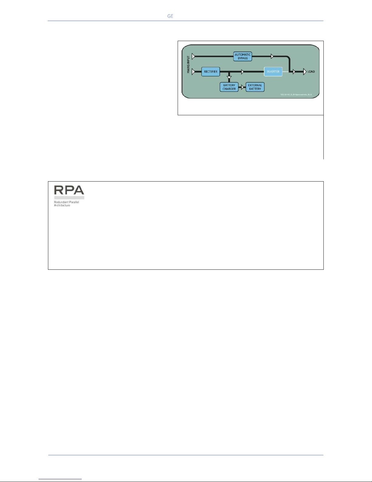
4.2.3 Mains Failure Operation
When the Mains is no longer within acceptable tolerances,
the Battery will provide the DC power to the Inverter.
The Inverter will maintain continuous AC power to the
Load until the Battery Voltage reaches the lower limit of
the Inverter operation capability.
During the discharge, the LCD screen shows the estimated
time the Battery can support the critical Load.
Prior to complete Battery discharge, the "stop operation"
alarm (shut-down imminent) warns the operator that the
Battery is almost discharged and the UPS is about to shut
down.
Fig. 4.2.3-1 Block diagram Mains Failure operation
In case of RPA Parallel System
With a Parallel System for power capacity (see Section 4.3)
With the Bypass Mains power available, a “Battery low” warning on any unit will cause the Load
to be transferred to Mains (after a selectable time delay).
With Bypass Mains power not available, a “Battery low” warning on any unit will start the “stop
operation” timer (adjustable).
The Load will shut down at the end of the “stop operation” time period.
With a Parallel System for redundancy (see Section 4.3)
When a Battery low warning occurs on a unit not necessary to support the present Load, this unit
will shut down after a timeout period (selectable).
The Load is shared between the other units.
As the warning occurs on one unit necessary to support the present Load, the system starts the
"stop operation" timeout (selectable).
The Load will shut down at the end of the “stop operation” time period.
4.2.4 Mains Recovery Operation
As soon as the AC input power recovers, the Rectifier will
start automatically, supplying DC power to the Inverter
and recharging the Battery.
If the Inverter was previously shut down due to low
Battery, the Load will be initially powered by Mains
through the Automatic Bypass.
When the Battery is sufficiently recharged to ensure a
minimum time of operation with the present Load, the
Inverter will start automatically and the Load will be
transferred back to the Inverter.
Fig. 4.2.4-1 Block diagram Mains recovery operation
In case of RPA Parallel System
When the AC input power recovers, the Rectifiers will start-up sequentially, according to their
number in the Parallel System. This minimizes the initial inrush current.
The Inverters will start-up automatically, but only when the Battery has been sufficiently recharged
for a minimum runtime with the present Load.
When enough Inverters to supply the Load have been restarted, the Load will be transferred from
the Automatic Bypass back to the Inverter output.
Page 19
Critical Power
Modifications reserved
Page 19/146
GE_UPS_OPM_TLE_SCE_M60_M80_1GB_V020.docx
User Manual TLE Series 600 & 800 CE S1
4.2.5 Automatic Bypass
In normal operation, the Load is supplied by
the Inverter.
When the control system detects a fault in
the Inverter, an overload condition or a shortcircuit condition, the Automatic Bypass will
transfer the critical Load to the Mains without
interruption.
Fig. 4.2.5-1 Block diagram Automatic Bypass
When the Inverter recovers, or the overload or short-circuit condition is corrected, the Load will be
automatically transferred back to the Inverter.
If the UPS is unable to return to normal mode following an automatic transfer to Bypass mode, an
alarm condition will be initiated.
In case of RPA Parallel System
Each unit has its own internal Bypass.
These units are continuously exchanging information, enabling all of the internal Bypass circuits in a
Parallel System to operate simultaneously.
If the Inverter of a unit fails, its Bypass circuit remains available to the Parallel System.
It is excluded only if the unit is separated from the common bus by opening its output switch Q1.
Page 20
Critical Power
Modifications reserved
Page 20/146
GE_UPS_OPM_TLE_SCE_M60_M80_1GB_V020.docx
User Manual TLE Series 600 & 800 CE S1
4.3 RPA PARALLEL SYSTEM OPERATION
4.3.1 Introduction to the RPA Parallel System
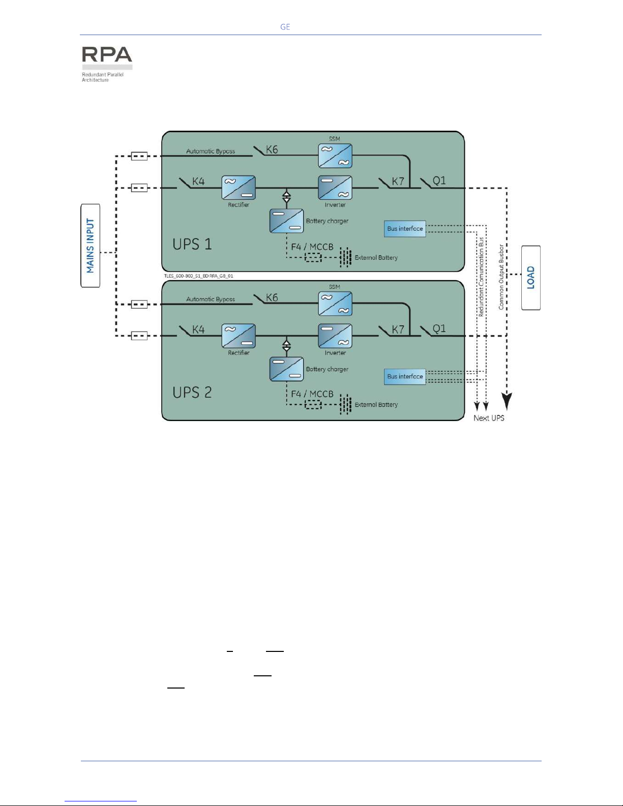
Fig. 4.3.1-1 Block diagram RPA Parallel System operation
Two or more equal power units can be paralleled to increase the output power (paralleling for capacity)
or to improve the overall reliability of an UPS system (paralleling for redundancy).
The outputs of parallel units are connected to a common power bus, and in normal operation the units
connected on the parallel bus share the Load equally.
The modular concept of TLE Series allows parallel operation of up to 6 units, without using paralleling
switchgear, external bypass circuits or common control circuitry (see Fig. 4.3.1-1).
Parallel units for power capacity
Several units can be paralleled in order to achieve output power greater than the maximum power of a
single unit.
The maximum total power shared between the paralleled units is equal to the total installed nominal
power.
In the event of a failure of one unit, the power supplied by the UPS system becomes insufficient and the
Load will be transferred to the Mains Bypass source.
Parallel units for redundancy
The nominal power rating of the n out of n+1 redundant paralleled modules must be equal to or higher
than the required Load power.
The Load will be equally shared by the n+1 units connected on the output bus.
Should one of the n+1 paralleled units trip Off-line, the remaining (n) modules will supply the Load,
maintaining conditioned power to the critical Load.
From this results higher reliability and security for the Load plus a higher MTBF (Mean Time Between
Failures).
Page 21
Critical Power
Modifications reserved
Page 21/146
GE_UPS_OPM_TLE_SCE_M60_M80_1GB_V020.docx
User Manual TLE Series 600 & 800 CE S1
4.3.2 Features of RPA Parallel System
The TLE Series 600 & 800 Parallel System is designed to provide a complete Redundant Parallel
Architecture, and is free from common equipment.
Not only the Inverters but also the Bypass functions are redundant.
When one UPS needs maintenance or service, the Load is powered by the other units.
The redundant communication bus to which all units are connected keeps each unit informed about the
status of all the other units.
The control panel located on each unit allows controlling and monitoring the status of this unit.
4.3.3 System control
A high-speed redundant, serial communication bus, guarantees the exchange of data and thus the
communication between the CPU's of each unit.
Each module controls is own function and operational status and communicates with all other modules,
in order to act or react if necessary, adapting to the new conditions.
4.3.4 Synchronization
All units are identical, but one unit is arbitrarily selected as the reference and all the other units
synchronize to this unit, which in turn synchronizes to the Mains Bypass voltage, as long as the latter is
within tolerances.
In case of reference failure, another unit in the Parallel System is automatically chosen to take over the
reference role.
The Bypass Input for all the units of the Parallel System must be supplied from the same AC source (no
phase shift allowed between them).
4.3.5 Load sharing
On each unit of the Parallel System, Inverter Output Voltage and Current are measured and applied to a
Load sharing bus.
An eventual difference between the units is therefore automatically equalized.
NOTE !
It is strongly recommended that no transformers, automatic circuit breakers or
fuses should be installed between the units output and the Load common bus bars.
However, it is recommended that a disconnection or isolation switch is installed in
order to totally isolate a unit if needed.
Page 22
Critical Power
Modifications reserved
Page 22/146
GE_UPS_OPM_TLE_SCE_M60_M80_1GB_V020.docx
User Manual TLE Series 600 & 800 CE S1
4.3.6 IEMi Operation Mode (option)
NOTE !
IEMi and eBoost Operation Mode are mutually exclusive; they cannot be
simultaneously available on a system.
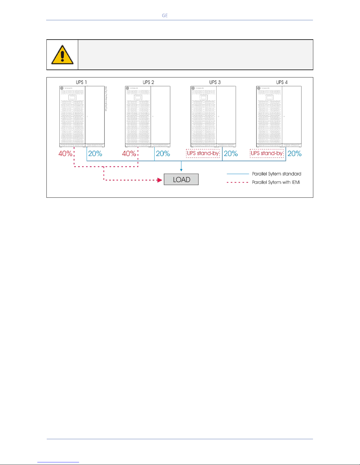
Fig. 4.3.6-1 Functional diagram of a Parallel System RPA in IEMi Operation Mode
GE offers the IEMi - Intelligent Energy Management integrated option to optimize energy cost while
maintaining the highest possible reliability for Parallel Redundant Uninterruptible Power Supply units
(max. 6).
For Parallel System installations, secured with Redundant Parallel Architecture™ (RPA™), IEMi Operation
Mode saves energy by dynamically utilizing the UPS units as needed to meet the required load without
compromising the power quality to the critical load.
The software will calculate the number of UPS units which are needed for load supply based on
following:
• Redundancy (N+1 or N+2) • System Load • Rectifier status
• Inverter operating time • IEMi Operation Mode programming
Particularly, the UPS control logic determines the minimal set of UPSs required to maintain a reliable
supply to the critical load.
Then, an efficiency optimization algorithm determines the best UPS configuration in order to maintain
the running UPS in their highest efficiency operating region.
Energy losses are reduced by switching the inverter section of one or more units to a stand-by state.
The critical load is fed by the remaining units operating in double-conversion.
As load increases, other units are gradually switched on-line in order to maintain the required
redundancy level.
The IEMi - Intelligent Energy Management integrated option is only available on parallel installations.
It is clear that in order to enjoy the benefits of IEMi operation a system programmed for N+1
redundancy requires a parallel installation of at least three UPSs, while four UPSs are required for N+2
redundancy.
IEMi - Intelligent Energy Management integrated is an option, and it is available only if introduced at the
factory, or if introduced in field installations by a GE GLOBAL SERVICES FIELD ENGINEER.
Benefits of IEMi - Intelligent Energy Management integrated include:
• Higher efficiency (reduced losses) in low-load conditions (efficiency optimization).
• No compromise on power quality (double-conversion operation).
• No compromise on system reliability (redundant operation).
Page 23

Critical Power
Modifications reserved
Page 23/146
GE_UPS_OPM_TLE_SCE_M60_M80_1GB_V020.docx
User Manual TLE Series 600 & 800 CE S1
4.4 UPS PARALLELED ON THE SAME BATTERY
NOTE !
A parallel system with a Common Battery for two or more UPS (max. 4 units), requires
a particular installation and adequate setting of some parameters, (accessible only
through password), and can therefore only be done by a GE QUALIFIED ENGINEER.
Usually each UPS Unit runs with its own Battery.
In case of parallel units running with a Common Battery (max. 4 UPS - see Fig. 4.4-1), the sharing circuit
between the individual UPS is integrated in the communication bus of the system in order to assure an
equal sharing of the Rectifiers output currents.
Fig. 4.4-1 Diagram RPA system with UPS on common battery
1 –
2 –
3 –
4 –
5 –
6 –
7 –
Rectifier
Inverter
Automatic Bypass
Mains Input
Load Bus Bar
External Battery Fuse
External Battery
Pay attention to the following recommendations:
The units delivered for this functioning mode needs a special parameters setting, so they must be
prepared in advance before the installation.
The installation must be performed only with the UPS system completely shut down.
The AC Rectifiers input power (4) must be the same, with clockwise phase rotation for each unit.
Each Rectifier must be set for the same floating DC voltage and the same Battery current limitation.
It is mandatory to install the fuses / MCB (6) on each line connecting the Rectifiers to the common
Battery for maintenance / safety reasons (see Section 5.8.2).
In case a unit must be powered down for maintenance, switch-OFF the concerned unit before open
the DC fuses / MCB on the Battery line (6).
It is recommended to connect an external NO free contact “Battery Fuses” to the UPS and to enable
the function by setting the parameter (see Section 9.2).
If an emergency generator set supplies the UPS, and the free contact “Generator ON” is connected
to the Customer Interface, connect a separate NO free contact on each parallel unit.
The parameters enabling the Battery test, both manual and automatic, must be set in the same
mode on all the units sharing a Common Battery.
Do not connect the temperature sensor for automatic battery floating voltage compensation.
Do not enable the function Boost charge.
Page 24
Critical Power
Modifications reserved
Page 24/146
GE_UPS_OPM_TLE_SCE_M60_M80_1GB_V020.docx
User Manual TLE Series 600 & 800 CE S1
4.5 SERVICE AND TECHNICAL SUPPORT
For any request of technical support please
contact your local Service Centre.
Stamp of your local Service Centre (see page 3)
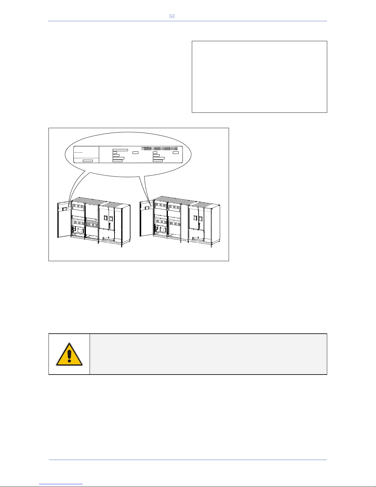
Fig. 4.5-1 Identification label
The requested data permitting
to identify your UPS are marked
on the identification label fixed
on the front of the cabinet,
behind the lower front door.
For fast and efficient technical
support please mention the data
marked on the identification
label.
4.6 WARRANTY
GE, operating through its authorised agents, warrants that the standard products will be free of defects
in materials and workmanship for a period as per contract specifications.
NOTE !
This warranty does not cover failures of the product which result from incorrect
installation, misuse, alterations by persons other than authorised agents, or
abnormal working conditions.
TLES_600-800_S1_Label identification_01
kVAOutput Power at Pow. factor
Output Freq. Hz
Output Voltage VAC: 3W + N + PE
Output Current A
lag.Series Product. Year
Input Freq. Hz
Input Voltage VAC: 3W + N + PE
Input Current A
Serial Nr.
Model
g
GE Digital Energy
6595 RIAZZINO (CH)
MADE IN SWITZERLAND
TLE Series 800
TLE Series 600
-
+
12
Q1
0 OFF
I ON
-
+
12
Q1
0 OFF
I ON
Page 25
Critical Power
Modifications reserved
Page 25/146
GE_UPS_OPM_TLE_SCE_M60_M80_1GB_V020.docx
User Manual TLE Series 600 & 800 CE S1
4.7 RECYCLING AT THE END OF SERVICE LIFE
NOTE !
This product has been designed to respect the
environment, using materials and components respecting
eco-design rules.
It does not contain CFCs (Carbon Fluor Clorid) or HCFCs
(Halogen Carbon Fluor Clorid).
RECYCLING AT THE END OF SERVICE LIFE !
GE’s Critical Power, in compliance with environment
protection recommends to the User that the UPS
equipment, at the end of its service life, must be
recovered conforming to the local applicable regulations.
BATTERY DISPOSAL
This product contains a battery that cannot be disposed
of as unsorted municipal waste in the European Union.
See the product documentation for specific battery
information.
The battery is marked with this symbol, which may
include lettering to indicate cadmium (Cd), lead (Pb), or
mercury (Hg).
For proper recycling return the battery to your supplier or
to a designated collection point.
For more information see: www.weeerohsinfo.com
Page 26
Critical Power
Modifications reserved
Page 26/146
GE_UPS_OPM_TLE_SCE_M60_M80_1GB_V020.docx
User Manual TLE Series 600 & 800 CE S1
5 INSTALLATION
5.1 TRANSPORT
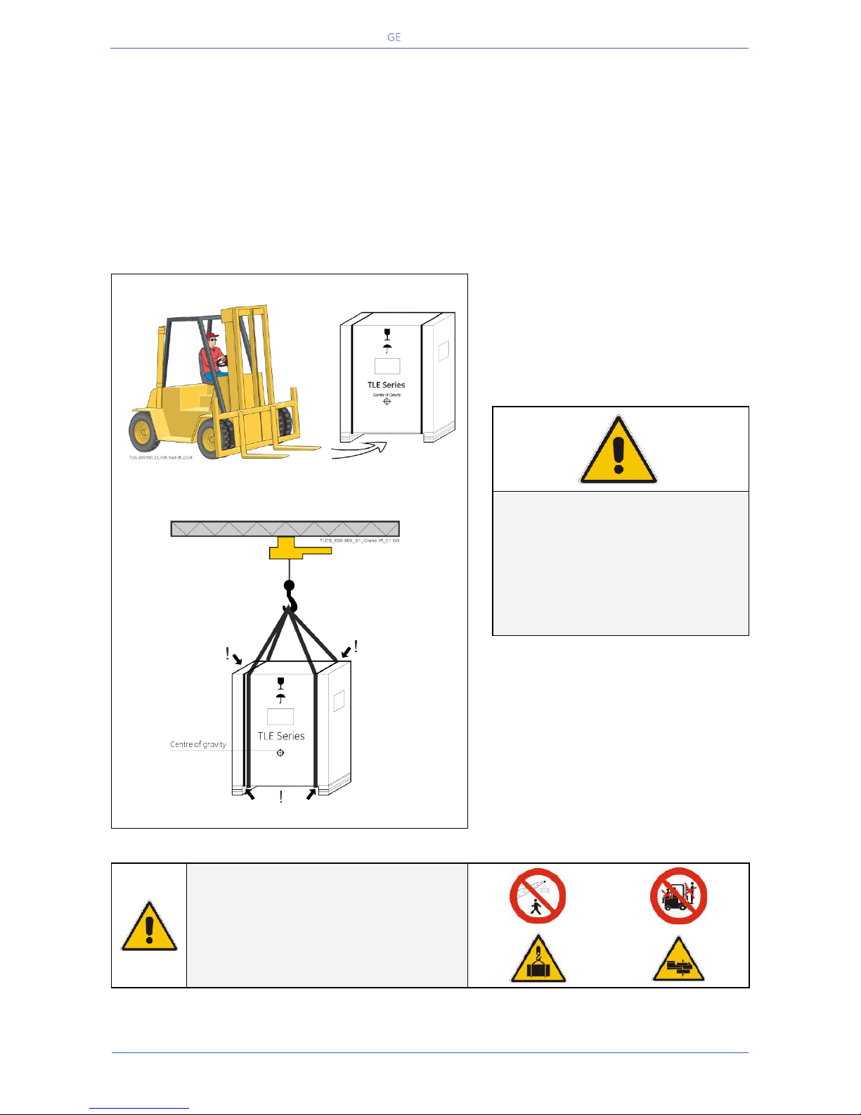
The UPS is packaged on a pallet suitable for handling with a forklift.
The UPS must be moved in upright position.
Do not tilt cabinets more than +/- 10° during handling.
Move the UPS in its original package to the final destination site.
Do not stack other packages on top: This could damage the UPS.
Forklift
Fig. 5.1-1 Position of the forklift when moving the unpacked UPS
Forklift
The UPS may be lifted with a forklift in
upright position.
Take note of the centre of gravity
marked on the package.
Crane
Fig. 5.1-2 Position of the carrying belts when moving the unpacked UPS
WARNING !
Check for sufficient floor and
elevator loading capacity.
Transport UPS only in upright
position.
Do not stack other package on top
of the UPS.
Crane
If the UPS has to be lifted by crane, use
suitable carrying belts taking note of the
centre of gravity marked on the
package.
Take all necessary precautions to
avoid damage to the cabinet while
hoisting the UPS.
WARNING !
When loading / unloading and when
moving the UPS, it is forbidden:
When loading / unloading and when
moving the UPS, pay attention to:
Page 27
Critical Power
Modifications reserved
Page 27/146
GE_UPS_OPM_TLE_SCE_M60_M80_1GB_V020.docx
User Manual TLE Series 600 & 800 CE S1
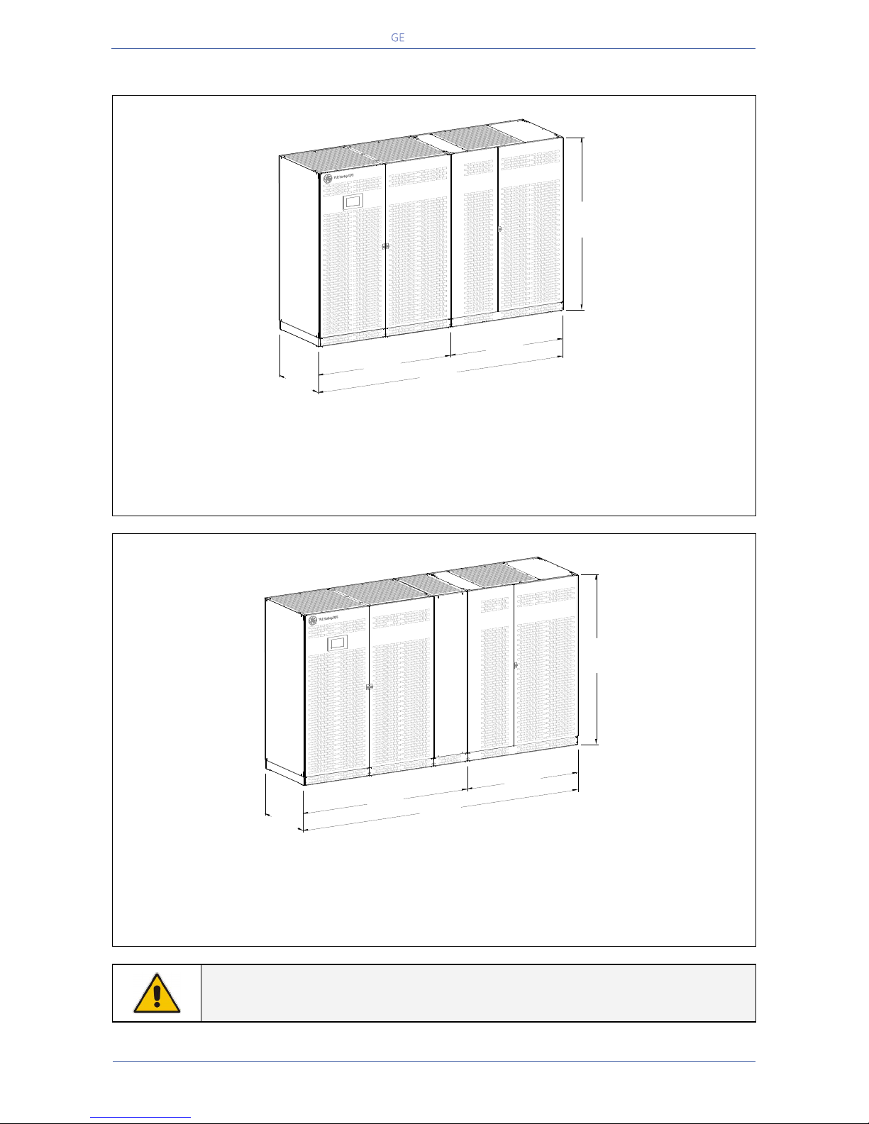
5.1.1 Dimensions and weights TLE Series 600 & 800
Dimensions and weights TLE Series 600
Dimensions (WxDxH):
3000 x 865 x 1905 mm / 118.12 x 34.06 x 75.00 inches
Weight:
Total UPS:
2200 kg
4850 lbs
“Power Section” cabinet:
1350 kg
2976 lbs
“In/Out Section“ cabinet:
850 kg
1874 lbs
Floor loading (total UPS):
848 kg/m2 / 174 lbs/sq.ft
Dimensions and weights TLE Series 800
Dimensions (WxDxH):
3420 x 865 x 1905 mm / 134.65 x 34.06 x 75.00 inches
Weight:
Total UPS:
2380 kg
5248 lbs
“Power Section” cabinet:
1650 kg
3638 lbs
“In/Out Section“ cabinet:
730 kg
1610 lbs
Floor loading (total UPS):
805 kg/m2 / 165 lbs/sq.ft
NOTE !
The weight of each single piece is marked outside the package!
34.06"
865mm
63.39"
1610 mm
75.00"
1905mm
118.12"
3000 mm
54.73"
1390 mm
Power Section cabinet
In/Out Section cabinet
TLES_UL_750_S1_UPS dimensions_GE_01
TLES_800_S1_UPS dimension_GE_01
865mm
34.06"
2025 mm
79.72"
3420 mm
134.65"
1395 mm
54.93"
Power Section cabinet
In/Out Section cabinet
1905mm
75.00"
Page 28
Critical Power
Modifications reserved
Page 28/146
GE_UPS_OPM_TLE_SCE_M60_M80_1GB_V020.docx
User Manual TLE Series 600 & 800 CE S1
5.2 DELIVERY
When delivered, inspect the package integrity and the physical condition of the cabinets carefully.
In case of any damage sustained during transport, immediately inform the carrier and contact your
local Service Centre.
A detailed report of the damage is necessary for any insurance claim.
NOTE !
A damaged UPS must never be installed or connected to Mains or Battery!
5.3 STORAGE
5.3.1 Storage of the UPS
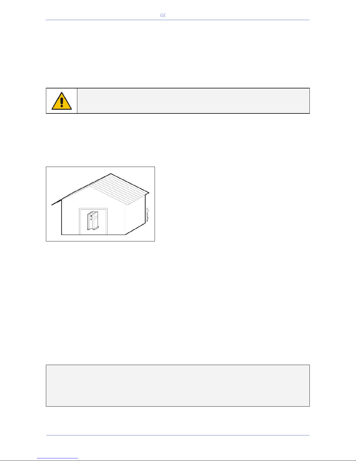
The equipment is carefully packed for transport and
storage so that it is in a perfect condition when eventually
installed.
Never leave an UPS outside the building and do not store
the UPS one on top of the other.
We recommend to store the UPS in its original package in
a dry, dust-free room, away from chemical substances,
and with a temperature range not exceeding -25°C (-13°F)
to 55°C (131°F).
In case the battery is included please refer to Section 5.3.2.
Some important functions of the UPS, such as the customized functions, are defined by parameters
stored in a RAM memory.
A small backup Battery located on the Control Unit board supplies the RAM.
If the storage time of the UPS exceeds 1 year, these functions should be verified by an authorized
Service Centre before putting the UPS into operation.
5.3.2 Storage of Battery
When the delivery includes a maintenance free Battery, keep in mind that they are subject to selfdischarge and therefore you must recharge the Battery.
The storage time without Battery recharge depends on the temperature of the storage site.
The optimal temperature for Battery storage is 20°C (68°F) to 25°C (77°F) and shall never exceed the
range -20°C (-4°F) to 40°C (104°F).
Recharge stored maintenance free Battery every:
6 months when the storage temperature is 20°C (68°F)
3 months when the storage temperature is 30°C (86°F)
2 months when the storage temperature is 35°C (95°F)
Page 29
Critical Power
Modifications reserved
Page 29/146
GE_UPS_OPM_TLE_SCE_M60_M80_1GB_V020.docx
User Manual TLE Series 600 & 800 CE S1
5.4 PLACE OF INSTALLATION
5.4.1 UPS location
NOTE !
UPS installation and connection must be performed by QUALIFIED SERVICE
PERSONNEL only.
If optional cabinets and accessories are included with the UPS, please refer to those
accompanying manuals for installation and operating instructions.
It is important to have a clean, dust-free environment provided with proper ventilation and airconditioning to keep the ambient temperature within the specified operating range.
The recommended air inlet temperature is from 20°C (68°F) to 25°C (77°F) (max. 40°C / 104°F).
Refer to Section 5.5.
Check for sufficient floor load capacity before installing the UPS and the Battery.
Refer to Section 5.1.1.
For Battery installation follow the local codes and the recommendation of the battery supplier.
NOTE !
Operation at temperatures higher than 25°C (77°F) will reduce battery life.
Potential consequences are explained in Section 11.1.4: read and understand them.
The TLE Series 600 & 800 UPS can radiate radio frequency energy.
Although some RFI (Radio Frequency Interference) filtering is inherent to the UPS there is no guarantee
that the UPS will not influence sensitive devices such as cameras and monitors that are positioned close
by.
If interference is expected, the UPS should be moved away from the sensitive equipment.
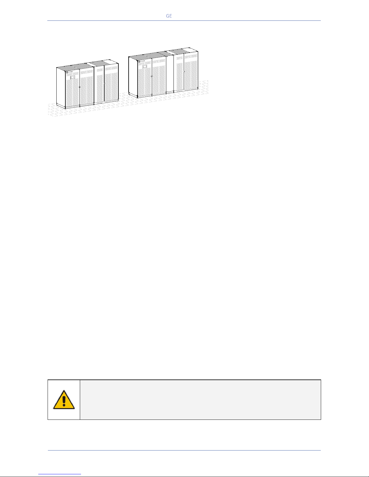
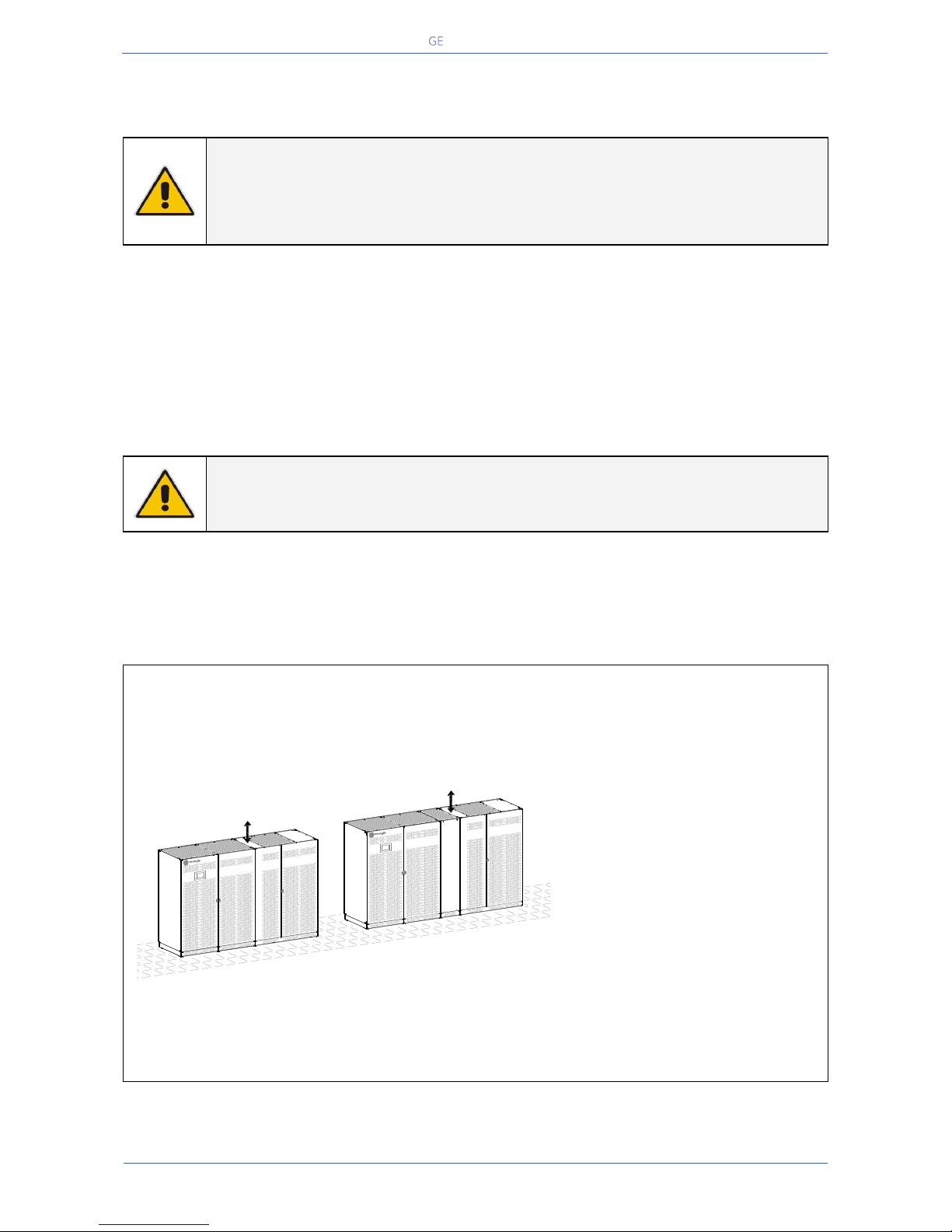
Positioning of the UPS TLE Series 600 & 800
Fig. 5.4.1-1 TLE Series 600 & 800 – Positioning of the UPS
The rear panel of the UPS may be
mounted flush to a wall or other
structure.
Clearance around the front of the
unit should be sufficient to enable
free passage of personnel with the
doors fully open, and to allow
sufficient airflow to the door vents.
To guarantee proper cooling air
exhaust, the recommended
minimum clearance between ceiling
and top of the UPS is 500mm (19.7”).
A single-phase power outlet (230
Vac) should be provided near the
UPS for connection of power tools,
test equipment or connectivity
devices.
This outlet must be grounded.
TLE Series 600
TLES_600-800_S1_UPS disposition_GE_01
TLE Series 800
Min.
20" / 500mm
Min.
20" / 500mm
Page 30
Critical Power
Modifications reserved
Page 30/146
GE_UPS_OPM_TLE_SCE_M60_M80_1GB_V020.docx
User Manual TLE Series 600 & 800 CE S1
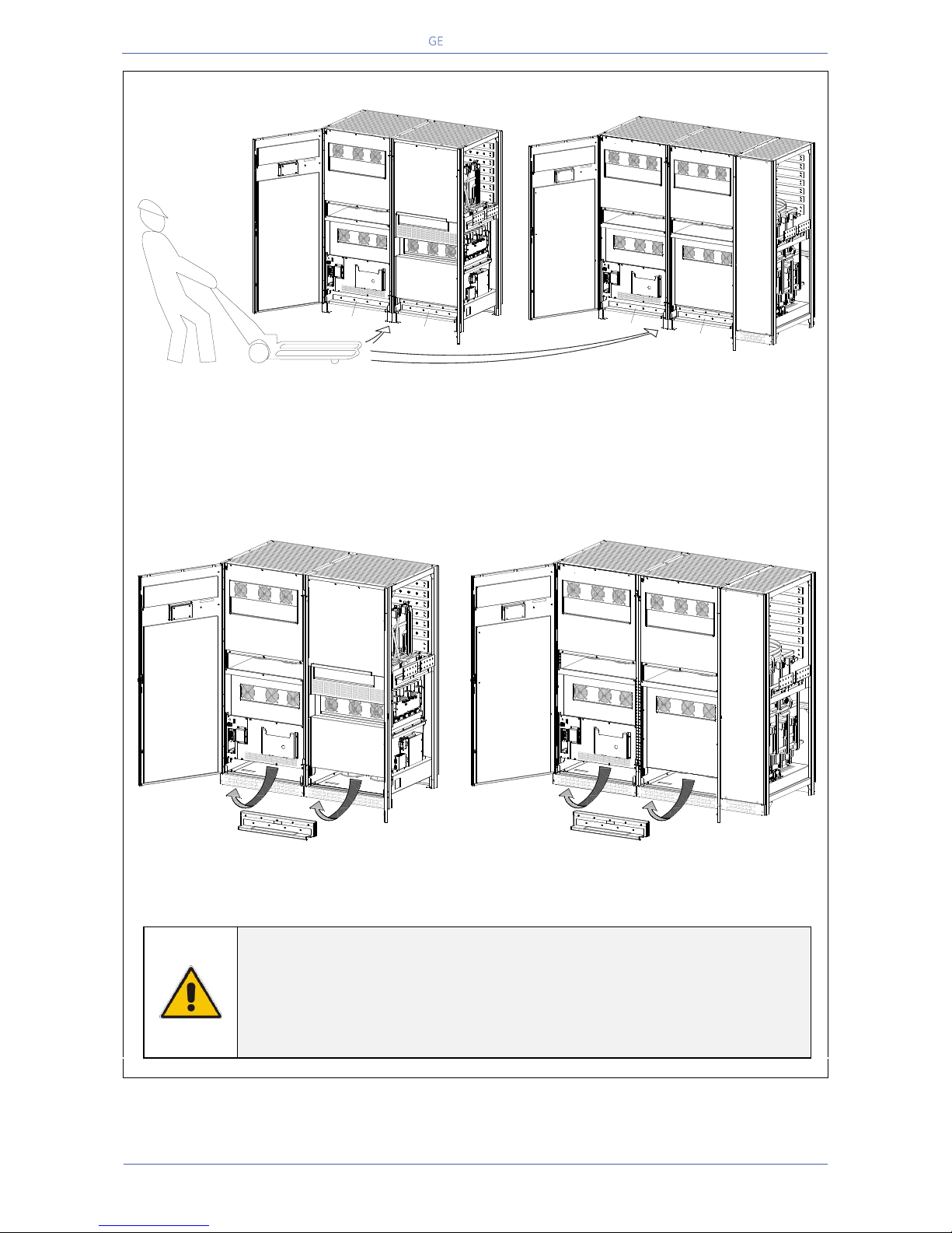
TLE Series 600 & 800 - Moving the UPS cabinet
Fig. 5.4.1-2 TLE Series 600 & 800 – Moving the UPS cabinet (“Power Section cabinet”)
TLE Series 600 & 800, positioned in the “Power Section cabinet”, is provided with two bases
reinforcement support (A) to avoid any damage during transportation of the UPS cabinet.
Fig. 5.4.1-3 TLE Series 600 & 800 – Removing the two bases reinforcement from the UPS cabinet (“Power Section cabinet”)
WARNING !
It’s MANDATORY REMOVE the two bases reinforcements (A) after installing
the UPS and before the start-up. See Fig. 5.4.1-3.
For any subsequent moving of the UPS cabinet is MANDATORY to re-install
the two bases reinforcement (A).
A
TLES_600-800_S1_UPS moving_01
EPO
-
+
12
A
TLE Series 800
“Power Section” cabinet
TLE Series 600
“Power Section” cabinet
EPO
-
+
12
A
A
EPO
EPO
-
+
12
A
EPO
EPO
-
+
12
TLE Series 800TLE Series 600
“Power Section” cabinet “Power Section” cabinet
A
TLES_600-800_S1_UPS moving_02
Page 31
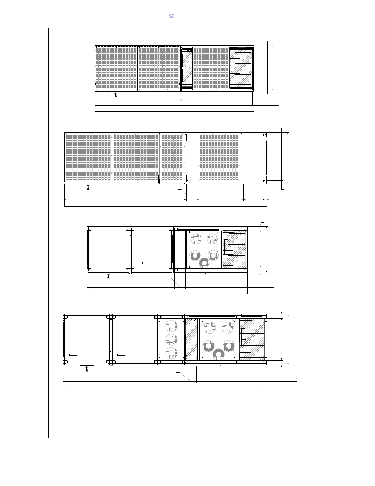
Critical Power
Modifications reserved
Page 31/146
GE_UPS_OPM_TLE_SCE_M60_M80_1GB_V020.docx
User Manual TLE Series 600 & 800 CE S1
TLE Series 600 & 800 - Openings for input and output cable connections
Fig. 5.4.1-4 TLE Series 600 – Openings on top of the cabinet for input and output cables connections
Fig. 5.4.1-5 TLE Series 800 – Openings on top of the cabinet for input and output cables connections
Fig. 5.4.1-6 TLE Series 600 – Openings on bottom of the cabinet for input & output cables connections
Fig. 5.4.1-7 TLE Series 800 – Openings on bottom of the cabinet for input & output cables connections
TLE Series 600 & 800 openings are provided on the top and the bottom of the UPS for the
connection of input and output cables.
Pay attention to the position of these openings, when choosing the placement of the UPS.
These openings are covered with a protective plate.
TLES_600_S1_UPS view top_01GB
FRONTAL SIDE
1640mm / 64.57 "
3000 mm / 118.12 "
700 mm / 27.56 "
750 mm / 29.53 "
865 mm / 34.06 "
64 mm / 2.52 "
51 mm / 2.00 "
35 mm / 1.38 "
200 mm
7.88 "
425 mm
16.73 "
Power Section cabinet In/Out Section cabinet
TLES_800_S1_UPS view top_01GB
FRONTAL SIDE
Power Section cabinet In/Out Section cabinet
2060 mm / 81.10 "
3420 mm / 134.65 "
700 mm / 27.56"
29.53 " / 750 mm
34.06 " / 865 mm
2.52 " / 64 mm
2.00 " / 51 mm
1.38 " / 35 mm
200 mm
7.88 "
16.73 "
425 mm
TLES_UL_750_S1_UPS view bottom_01
Power Section cabinet In/Out Section cabinet
1.38 " / 35 mm
27.56 " / 700 mm
34.06 " / 865 mm
3.50 " / 89 mm
3.00 " / 76 mm
16.73 "
425 mm
64.57 " / 1640 mm
118.12 " / 3000 mm
7.88 "
200 mm
27.56 " / 700 mm
FRONTAL SIDE
TLES_800_S1_UPS view bottom_01GB
FRONTAL SIDE
1.38 " / 35 mm
700 mm / 27.56 "
865 mm / 34.06 "
89 mm / 3.50 "
76 mm / 3.00 "
16.73 "
425 mm
Power Section cabinet In/Out Section cabinet
2060 mm / 81.10 "
3420 mm / 134.65 "
700 mm / 27.56"
200 mm
7.88 "
Page 32
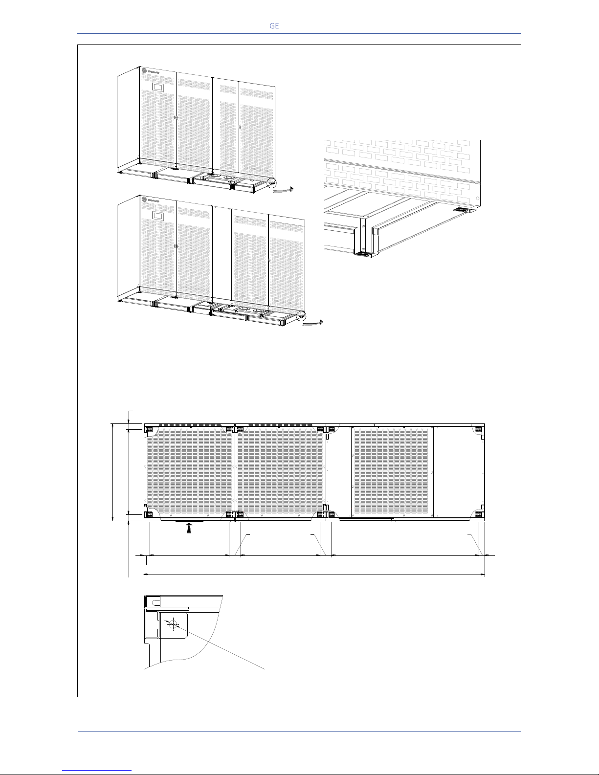
Critical Power
Modifications reserved
Page 32/146
GE_UPS_OPM_TLE_SCE_M60_M80_1GB_V020.docx
User Manual TLE Series 600 & 800 CE S1
Fixing of the UPS cabinet TLE Series 600 & 800 on the floor
Fig. 5.4.1.8 TLE Series 600 & 800 – Fixing of the UPS cabinet on the floor
The UPS cabinet is free standing and normally does not require to be bolted to the floor.
The UPS cabinet can be fixed however to the floor by bolting it with the supporting blocks to the
floor.
Fig. 5.4.1-9 TLE Series 600 – UPS cabinet floor fixing points
TLES_UL_750-1000_S1_UPS fixing_01
Power Section cabinet In/Out Section cabinet
750 mm / 29.53 "
60 mm / 2.37 "
865 mm / 34.06 "
54 mm / 2.13 "
TLES_600_S1_UPS fixing_02
FRONTAL SIDE
700 mm / 27.56 "
700 mm / 27.56 "
1275 mm / 50.20 "
3000 mm / 143.50 "
60 mm / 2.37 "
100 mm / 3.94 "
60 mm / 2.37 "
Ø 13.5mm / 0.53 "
Page 33
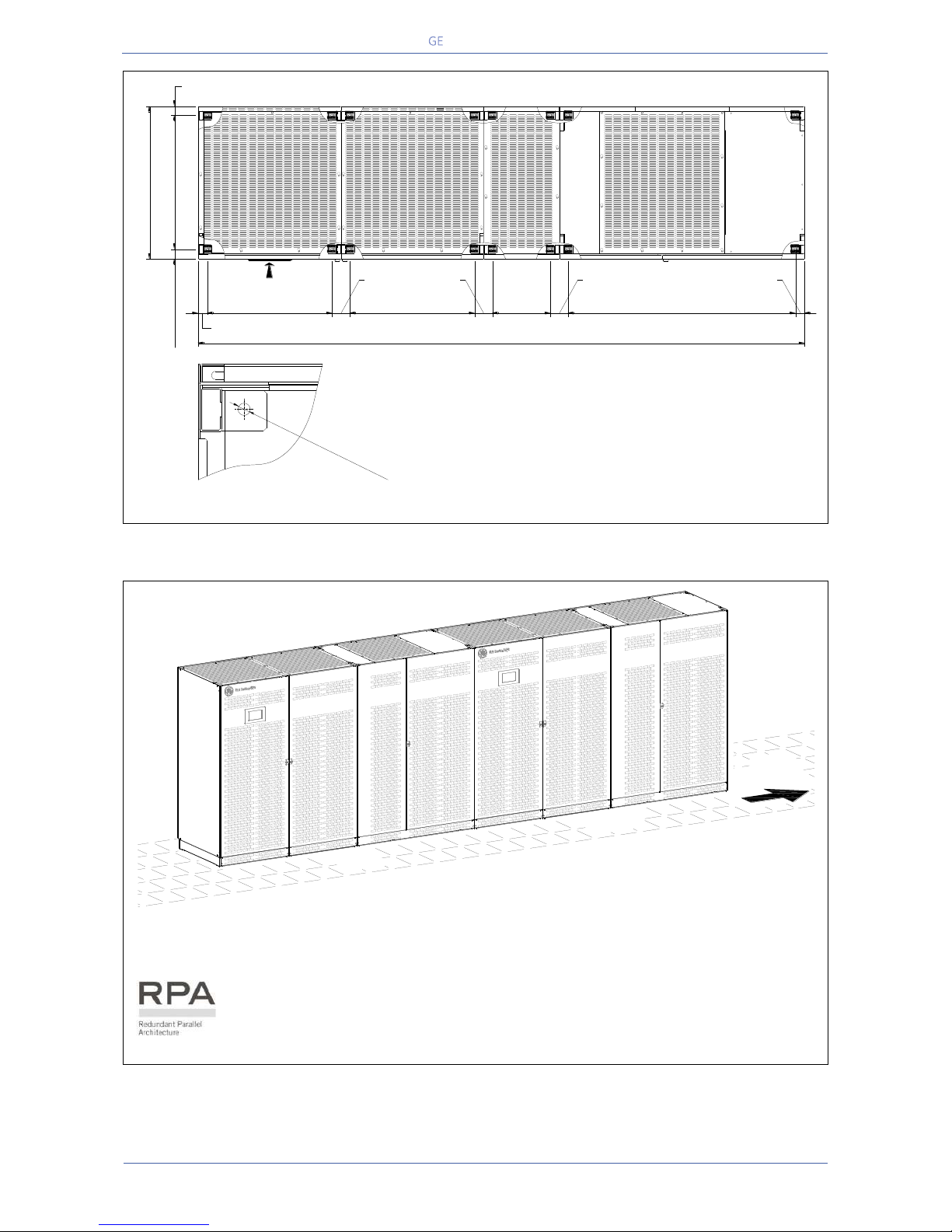
Critical Power
Modifications reserved
Page 33/146
GE_UPS_OPM_TLE_SCE_M60_M80_1GB_V020.docx
User Manual TLE Series 600 & 800 CE S1
Fig. 5.4.1-10 TLE Series 800 – UPS cabinet floor fixing points
Fig. 5.4.1-11 TLE Series 600 & 800 – RPA Parallel System disposition
In case of Parallel System, try to place the UPS modules in sequence of their numbers
(marked on the packing).
If the units are positioned “side by side”, the side panels must be mounted on all
units.
TLES_800_S1_UPS view top_01GB
FRONTAL SIDE
Power Section cabinet In/Out Section cabinet
750 mm / 29.53 "
60 mm / 2.37 "
865 mm / 34.06 "
54 mm / 2.13 "
700 mm / 27.56 "
700 mm / 27.56 "
60 mm / 2.36 "
1275 mm / 50.19 "
3420 mm / 134.65 "
325 mm
12.80 "
100 mm / 3.94 " 100 mm / 3.94 " 60 mm / 2.36 "
Ø 13.5mm / 0.53 "
TLES_600_S1_RPA disposition_GE_01GB
UPS 1
UPS 2
UPS
3 - 4 - 5 - 6
Page 34
Critical Power
Modifications reserved
Page 34/146
GE_UPS_OPM_TLE_SCE_M60_M80_1GB_V020.docx
User Manual TLE Series 600 & 800 CE S1
5.4.2 Battery location
Batteries require a well-ventilated room with controlled temperature to obtain reliable operation.
The Battery can be installed immediately adjacent to the UPS (left or right side) or remotely from the
UPS.
If the Battery is installed remotely from the UPS, a wall mounted DC disconnect device must be installed
within line-of-site to both the UPS and the Battery.
The optimal room temperature for the Battery is 20°C (68°F) to 25°C (77°F) and shall never exceed the
range -20°C (-4°F) to 40°C (104°F).
The life of valve-regulated batteries will be reduced by 50% for each additional 10°C (18°F) that the
Battery ambient temperature is above 25°C (77°F).
The Battery System associated with larger UPS is usually either rack mounted or installed in multiple
Battery Cabinets.
Installation and assembly must be made according to the local standards and Battery System
manufacturer‘s recommendations.
The Battery Circuit Breaker or Battery Fuse Box must be mounted as near as possible to the Battery.
WARNING !
Battery installation and connection must be performed by QUALIFIED PERSONNEL
only.
Read all safety instructions before proceeding with the installation (see Section 1).
Battery discharging and/or charging activities may cause the emission of
hydrogen gas; therefore, the room requires proper ventilation and fresh air.
Comply with the EN50272-2 standard.
Page 35
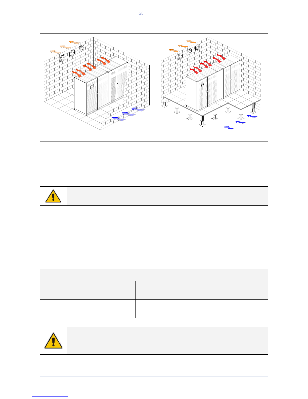
Critical Power
Modifications reserved
Page 35/146
GE_UPS_OPM_TLE_SCE_M60_M80_1GB_V020.docx
User Manual TLE Series 600 & 800 CE S1
5.5 VENTILATION AND COOLING
Fig. 5.5-1 Installation on plain floor
Fig. 5.5-2 Installation on raised floor
The heat produced by the UPS is transferred to the environment by its ventilation.
Air inlets for UPS ventilation are located on the front of the UPS, while air outlets are on top of the
cabinet.
A suitable ventilation or cooling system must be installed to extract the heat from the UPS room.
NOTE !
Do not put anything on the top of the cabinet.
Air filtering systems could be required when the UPS operates in a dirty environment.
In order to prevent overheating of the UPS, the available air intake flow rate must exceed the total air
exhaust flow rate requirement of the UPS system.
Contact your Dealer or the nearest Service Centre for appropriate solutions.
The below table indicates the heat dissipation at full Load at PF = 0.9 & 1 and charged Battery, up to
1000 m (3280 ft) altitude, for cooling air 25°C (77°F) to 30°C (86°F).
UPS model
Losses
Cooling air flow
VFI
eBoost™ (option)
VFI
PF = 0.9
PF = 1
PF = 0.9
PF = 1
PF = 0.9
PF = 1
TLE Series 600
20.7 kW
24.3 kW
6.5 kW
7.3 kW
6003 m3/h
7047 m3/h
TLE Series 800
27.7 kW
32.5 kW
8.7 kW
9.7 kW
8033 m3/h
9425 m3/h
NOTE !
Even when eBoost™ Operating Mode option is available, the ventilation and cooling
system shall be rated as for operation in VFI mode.
Air Extraction
Air Intake
TLES_600-800_S1_UPS ventilation_Raised floor_01GB
TLES_600-800_S1_UPS ventilation_Raised floor_01GB
Air Extraction
Page 36
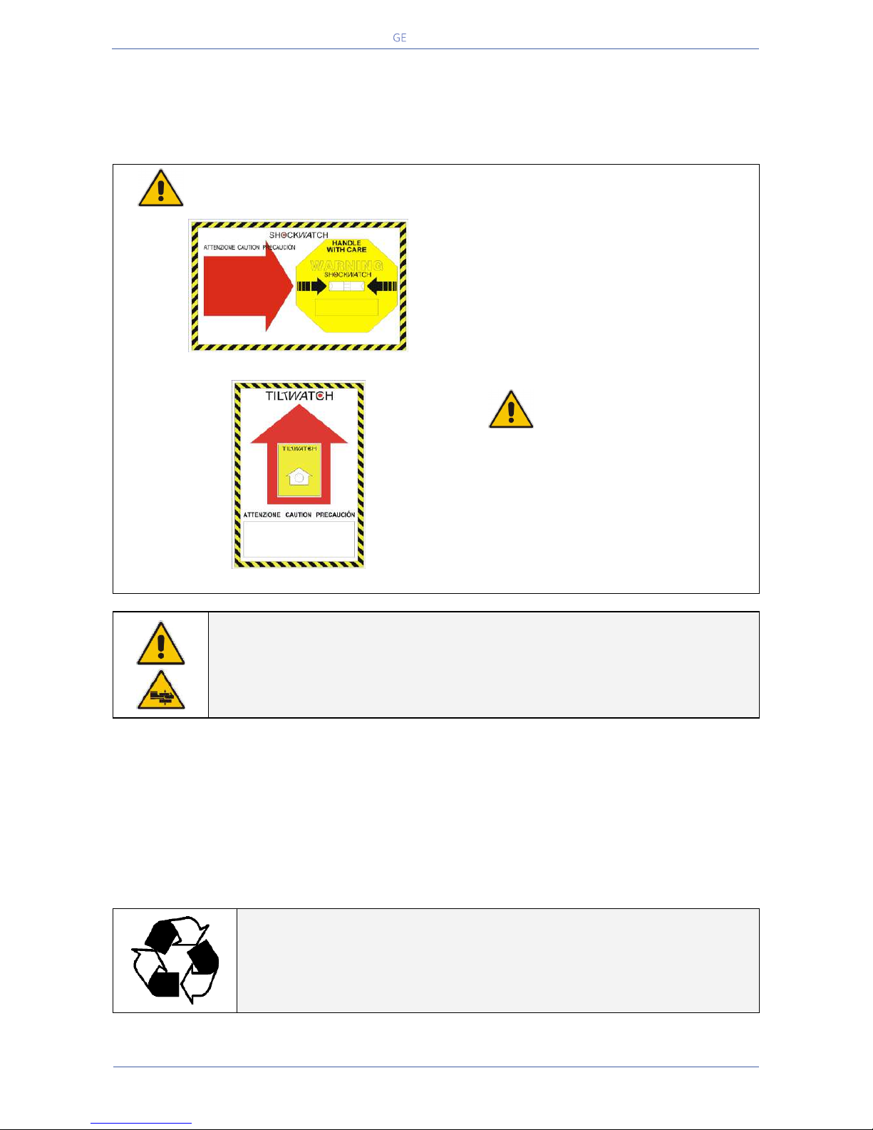
Critical Power
Modifications reserved
Page 36/146
GE_UPS_OPM_TLE_SCE_M60_M80_1GB_V020.docx
User Manual TLE Series 600 & 800 CE S1
5.6 UNPACKING
Move the equipment in it’s original packing, carton box or wooden case, until the place of installation
and remove the packing and the transport sockets only just before installing the UPS.
Be aware of the heavy weight of the UPS, pay attention when moving the UPS cabinet.
White colour = without any anomaly
Red colour = anomaly evidence
The package of the TLE Series 600 & 800
is equipped with ShockWatch (indicator
for shock), and TiltWatch (indicator for
overthrow) on the outside.
These devices indicate an eventual shock
or overthrow during transport.
Whenever these devices show a
possible anomaly, the UPS shall not be
commissioned before consulting a
“Service Centre”.
Fig. 5.6-1 ShockWatch device
Fig. 5.6-2 TiltWatch device
NOTE !
Be aware of the heavy weight of the UPS, pay attention when moving the UPS
cabinet.
Take care not to damage the UPS when moving by forklift.
Included in the delivery you can find the following parts:
An accessories bag.
Air inlet grids, which must be mounted on the bottom of the cabinet UPS with the screws included.
Bus bars interconnection “Power Section cabinet” and “In/Out Module cabinet”.
Junctions metal parts to connect “Power Section cabinet” and “In/Out Module cabinet”.
XD1 (46P) & XD2 (32P) control cables interconnection.
Control Bus cables for inter-connecting the UPS modules (only for the RPA system).
The documentation includes the “User Manual” and the “UPS Safety Rules”.
PACKING MATERIAL RECYCLING
GE’s Critical Power, in compliance with environment protection, use only
environmentally friendly material.
UPS packing materials must be recycled in compliance with all applicable
regulations.
Page 37
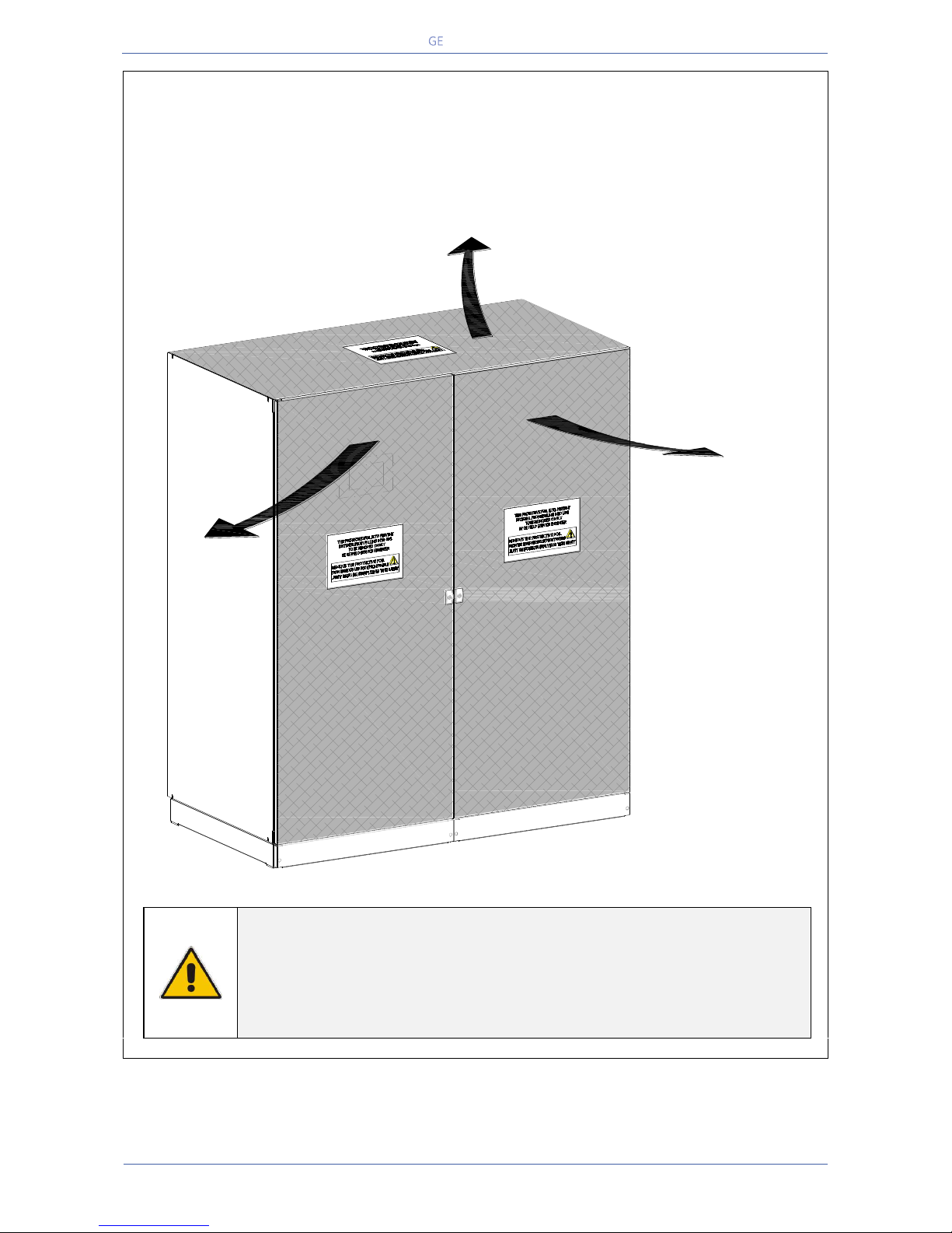
Critical Power
Modifications reserved
Page 37/146
GE_UPS_OPM_TLE_SCE_M60_M80_1GB_V020.docx
User Manual TLE Series 600 & 800 CE S1
PROTECTIVE FOIL
TLE Series is provided with a “PROTECTIVE FOIL”, on the roof and door/front panels, to prevent
material from falling into UPS.
WARNING !
It’s MANDATORY TO REMOVE the “PROTECTIVE FOIL” but only just before the
first start-up of the UPS as indicated in the appropriate label!
The removal of the "PROTECTIVE FOIL" should be performed only by a GE
FIELD SERVICE ENGINEER!
TLES_UPS Protective foil_01GB
PROTECTIVE FOIL
to remove as indicated
in the label
PROTECTIVE FOIL
to remove
as indicated
in the label
PROTECTIVE FOIL
to remove as indicated
in the label
Page 38
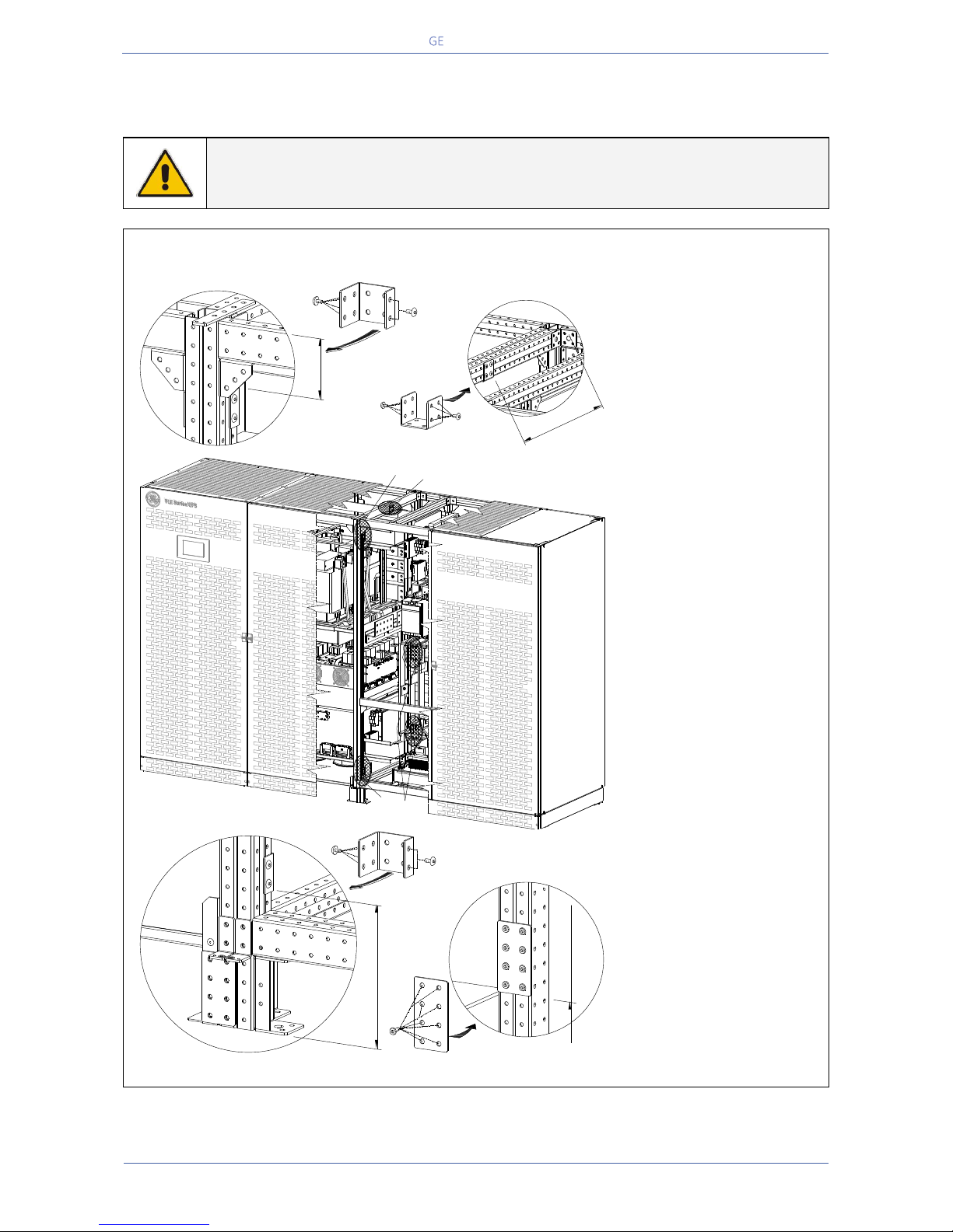
Critical Power
Modifications reserved
Page 38/146
GE_UPS_OPM_TLE_SCE_M60_M80_1GB_V020.docx
User Manual TLE Series 600 & 800 CE S1
5.7 INTER CABINET CONNECTIONS
5.7.1 Cabinets positioning and interconnection
NOTE !
The “Power Section cabinet” and “In/Out Section cabinet” must be installed on
leveled floor.
TLE Series 600 - Cabinets positioning and interconnection
Fig. 5.7.1-1 TLE Series 600 – Cabinets positioning and interconnection
TLE Series 600, in
standard version, is
delivered split into two
cabinets, “Power Section
cabinet” and “In/Out
Section cabinet”.
Align them together with
the “Power Section
cabinet” on the left side
(cabinet with Control
Panel).
See Fig. 5.7.1-1.
Pay attention, that no
loose cables are trapped
when pushing the
cabinets together.
Once finally positioned,
the two cabinets have to
be connected together
with power and control
wiring.
Refer to Section 5.7.2 and
5.7.3.
8 Bolt M6x12
Fixing type 2
Fixing type 3a
6 Bolt M6x12
Fixing type 1 (2 pc.)
8 Bolt M6x12
from base
6 Bolt M6x12
Fixing type 3b
In/Out Section cabinet
Power Section cabinet
TLES_600_S1_UPS connection cabinets_GE_01GB
3a
2
3b
1
14.77"
375 mm
3.94"
100 mm
9.97"
253 mm
35.55"
903 mm
6.89"
175 mm
Page 39
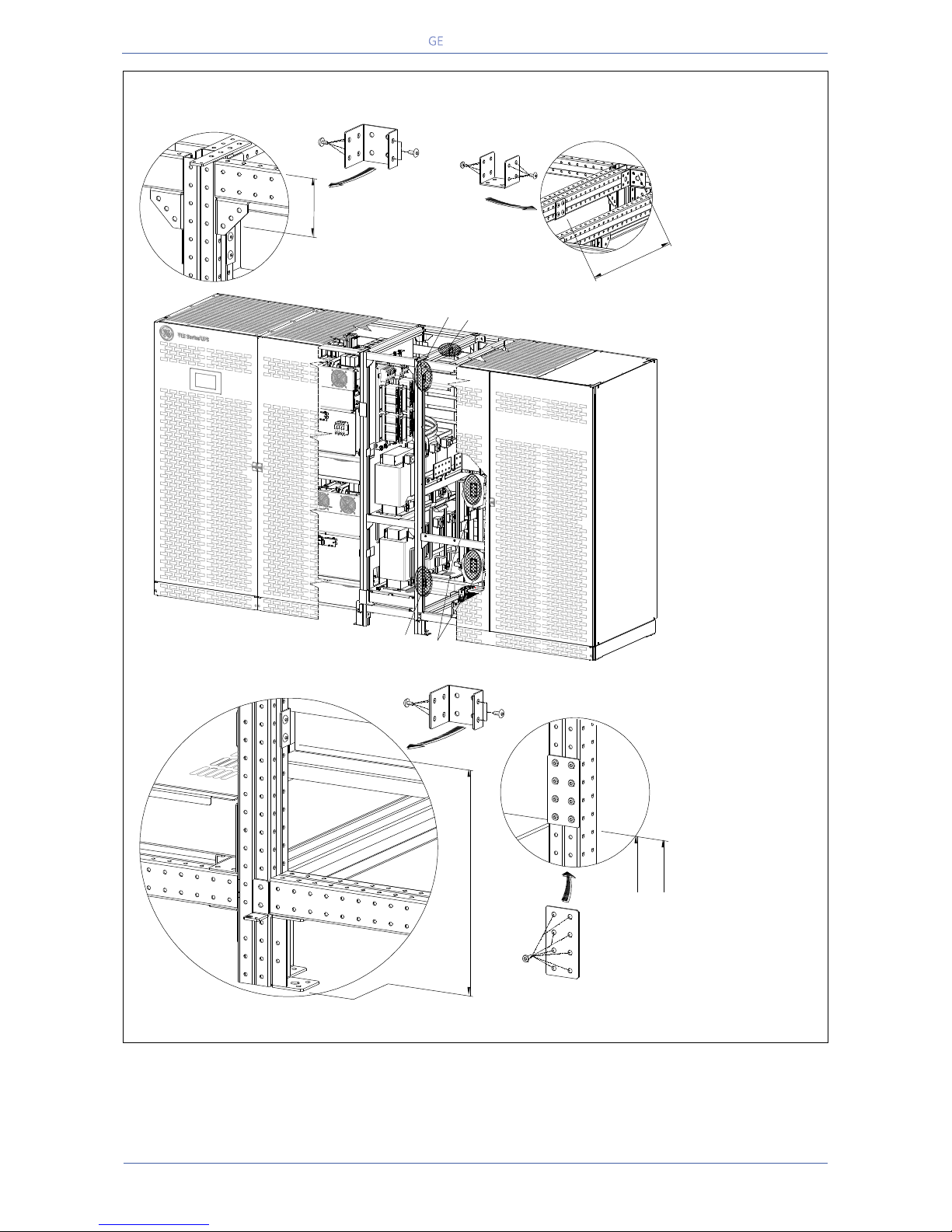
Critical Power
Modifications reserved
Page 39/146
GE_UPS_OPM_TLE_SCE_M60_M80_1GB_V020.docx
User Manual TLE Series 600 & 800 CE S1
TLE Series 800 - Cabinets positioning and interconnection
Fig. 5.7.1-2 TLE Series 800 – Cabinets positioning and interconnection
TLE Series 800, in
standard version,
is delivered split
into two cabinets,
“Power Section
cabinet” and
“In/Out Section
cabinet”.
Align them
together with the
“Power Section
cabinet” on the left
side (cabinet with
Control Panel).
See Fig. 5.7.1-2.
Pay attention, that
no loose cables
are trapped when
pushing the
cabinets together.
Once finally
positioned, the
two cabinets have
to be connected
together with
power and control
wiring.
Refer to Section
5.7.2 and 5.7.3.
8 boltsM6x12
Fixing type 2
375 mm
14.77"
Fixing type 3a
6 boltsM6x12
100 mm
3.94"
Fixing type 1 (2 pz.)
253 mm
9.97"
777 mm
30.60"
8 bolts M6x12
from base
6 bolts M6x12
Fixing type 3b
325 mm
12.80"
TLES_800_S1_UPS connection cabinets_GE_01GB
Power Section cabinet
In/Out Section cabinet
3b
1
2
3a
Page 40
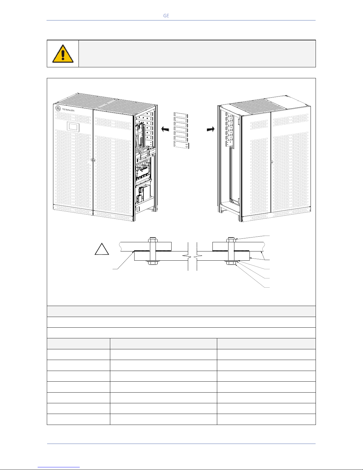
Critical Power
Modifications reserved
Page 40/146
GE_UPS_OPM_TLE_SCE_M60_M80_1GB_V020.docx
User Manual TLE Series 600 & 800 CE S1
5.7.2 Bus bars interconnection
WARNING !
All the bus bars interconnection must be performed by QUALIFIED SERVICE
PERSONNEL only.
TLE Series 600 - Bus bars interconnection
Fig. 5.7.2-1 TLE Series 600 – Bus bars interconnection
Torque Specifications
BOLT Size (mm): M10
BOLT Torque (N-m): 40
Connection
Description of connection
Bus bars interconnection
L1 Inverter
Interconnection L1 Inverter
1 Bus bar 60/10 x 270 mm
L2 Inverter
Interconnection L2 Inverter
1 Bus bar 60/10 x 270 mm
L3 Inverter
Interconnection L3 Inverter
1 Bus bar 60/10 x 270 mm
L1 Rectifier
Interconnection L1 Rectifier
1 Bus bar 60/10 x 270 mm
L2 Rectifier
Interconnection L1 Rectifier
1 Bus bar 60/10 x 270 mm
L3 Rectifier
Interconnection L1 Rectifier
1 Bus bar 60/10 x 270 mm
N - Neutral
Interconnection N - Neutral
1 Bus bar 100/10 x 270 mm
Bus bars interconnection
L1 Inverter
L2 Inverter
L3 Inverter
L1 Rectifier
N - Neutral
L2 Rectifier
L3 Rectifier
TLES_600_S1_UPS connection cabinets_GE_02GB
Power Section cabinet
In/Out Section cabinet
Detail showing bus bars interconnection
M10 Pre Fixed Nut
M10 Flat Washer
M10 Spring Washer
M10x35 Bolt
Bus Bar
Use the dedicated conductor
termination compound.
Example: PENETROX E
manufactured by BURNDY
!
Page 41
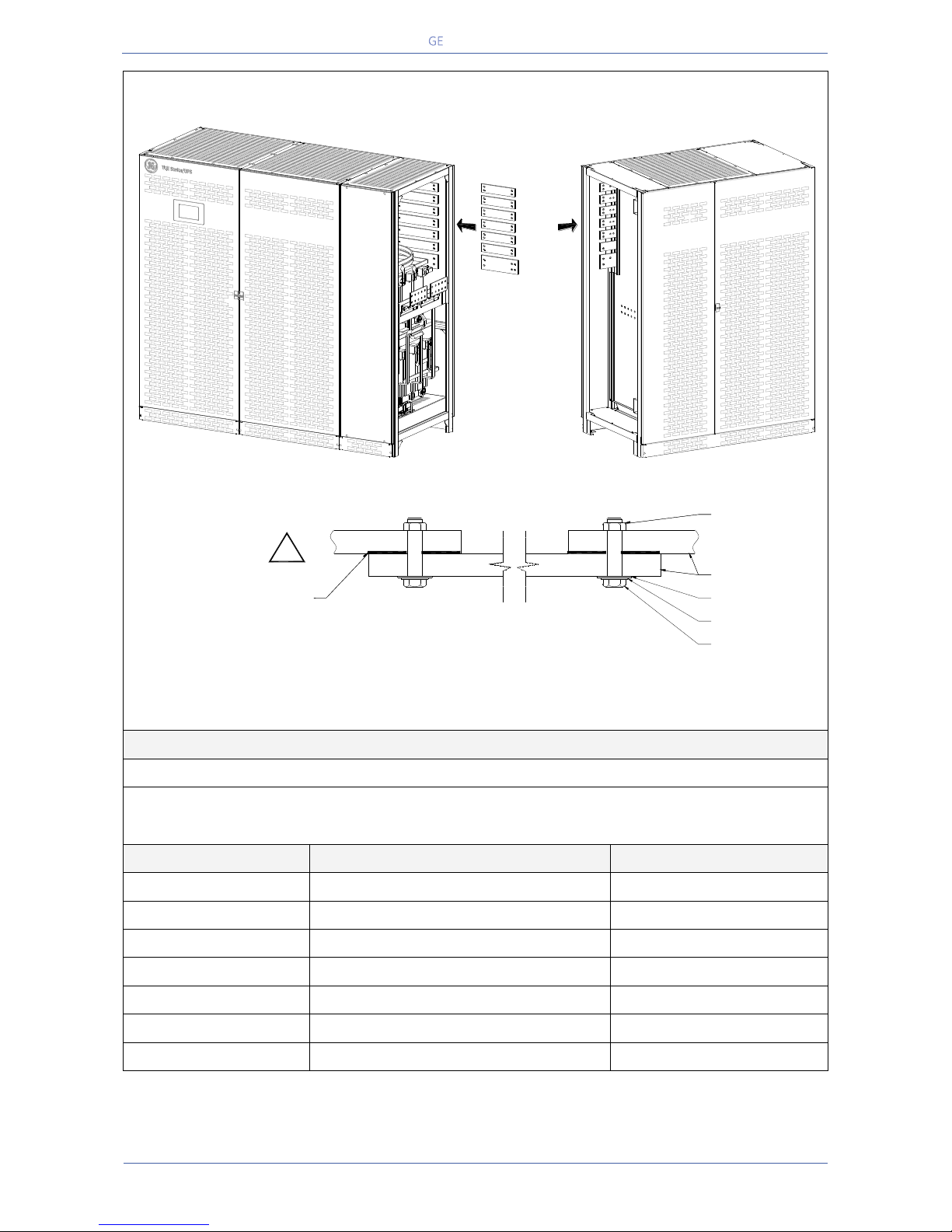
Critical Power
Modifications reserved
Page 41/146
GE_UPS_OPM_TLE_SCE_M60_M80_1GB_V020.docx
User Manual TLE Series 600 & 800 CE S1
TLE Series 800 - Bus bars interconnection
Fig. 5.7.2-2 TLE Series 800 – Bus bars interconnection
Torque Specifications
BOLT Size (mm): M10
BOLT Torque (N-m): 40
Connection
Description of connection
Bus bars interconnection
L1 Inverter
Interconnection L1 Inverter
1 Bus bar 60/10 x 270 mm
L2 Inverter
Interconnection L2 Inverter
1 Bus bar 60/10 x 270 mm
L3 Inverter
Interconnection L3 Inverter
1 Bus bar 60/10 x 270 mm
L1 Rectifier
Interconnection L1 Rectifier
1 Bus bar 60/10 x 270 mm
L2 Rectifier
Interconnection L1 Rectifier
1 Bus bar 60/10 x 270 mm
L3 Rectifier
Interconnection L1 Rectifier
1 Bus bar 60/10 x 270 mm
N - Neutral
Interconnection N - Neutral
1 Bus bar 100/10 x 270 mm
In/Out Section cabinet
Detail showing bus bars interconnection
M10 Pre Fixed Nut
M10 Flat Washer
M10 Spring Washer
M10x35 Bolt
Bus Bar
Bus bars interconnection
L1 Inverter
L2 Inverter
L3 Inverter
L1 Rectifier
N - Neutral
L2 Rectifier
L3 Rectifier
TLES_800_S1_UPS connection cabinets_GE_02GB
Power Section cabinet
Use the dedicated
conductor termination compound.
Example: PENETROX E
manufactured by BURNDY
!
Page 42
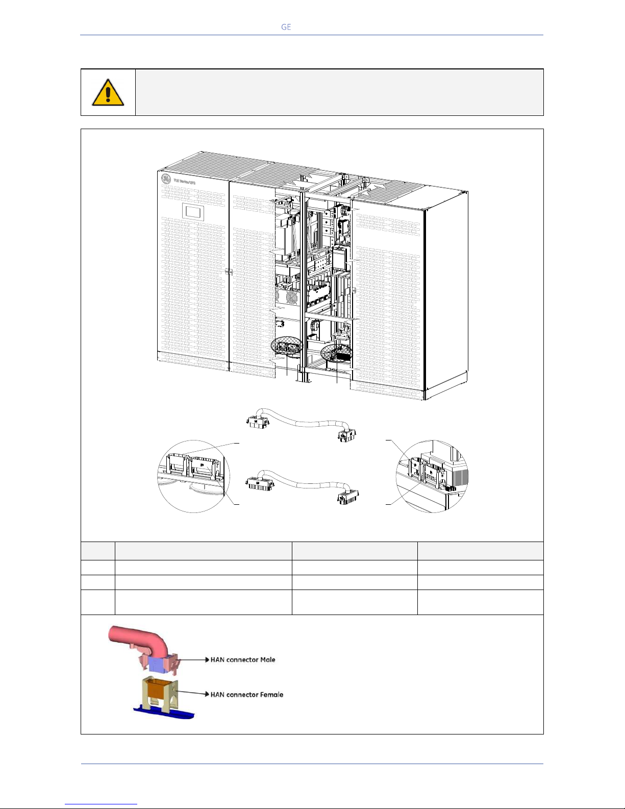
Critical Power
Modifications reserved
Page 42/146
GE_UPS_OPM_TLE_SCE_M60_M80_1GB_V020.docx
User Manual TLE Series 600 & 800 CE S1
5.7.3 Control cables interconnection
WARNING !
All the cables interconnection must be performed by QUALIFIED SERVICE
PERSONNEL only.
TLE Series 600 - Control cables interconnection
Fig. 5.7.3-1 TLE Series 600 – Control cables interconnection
Pos.
Connection
From
Connecting to
1
XD1 – HAN Connector male (46 poles)
“Power Section cabinet”
“In/Out Section cabinet”
2
XD2 - HAN Connector male (32 poles)
“Power Section cabinet”
“In/Out Section cabinet”
3
XTR2A - Connector
“Power Section cabinet”
“In/Out Section cabinet”
XTR2 Connector
Fig. 5.7.3-2 Connection of hearting connectors (HAN connectors)
NOTE: All these connections must be performed by
QUALIFIED SERVICE PERSONNEL only.
Proper dressing needs to be done for each cable
assembly in order to reduce the stress.
All the cables must be sufficiently (at least 10cm/4")
away from all live parts.
Cable binders used to support the wiring must NOT be
overly tightened.
XD1
(46 poles)
XD2
(32 poles)
XD1
(46 poles)
XD2
(32 poles)
XD2 Connector (32 poles)
1 2
In/Out Section cabinet
Power Section cabinet
TLES_600_S1_UPS connection cabinets_GE_03GB
1
2
XD1 Connector (46 poles)
Page 43
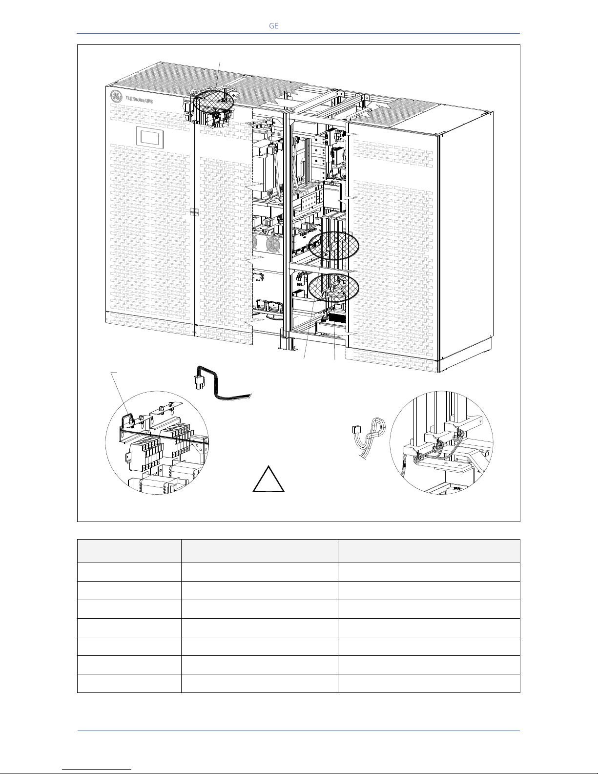
Critical Power
Modifications reserved
Page 43/146
GE_UPS_OPM_TLE_SCE_M60_M80_1GB_V020.docx
User Manual TLE Series 600 & 800 CE S1
Fig. 5.7.3-3 TLE Series 600 – Control cables interconnection
Connection
From (already connected)
To
XTR2A - Connector
“In/Out Section cabinet”
“Power Section cabinet” - XTR2 Connector
H9
“Power Section cabinet”
“In/Out Section cabinet” – H9 LEM
H10
“Power Section cabinet”
“In/Out Section cabinet” – H10 LEM
H11
“Power Section cabinet”
“In/Out Section cabinet” – H11 LEM
H13
“Power Section cabinet”
“In/Out Section cabinet” – H13 LEM
H14
“Power Section cabinet”
“In/Out Section cabinet” – H14 LEM
H15
“Power Section cabinet”
“In/Out Section cabinet” – H15 LEM
In/Out Section cabinet
Power Section cabinet
TLES_600_S1_UPS connection cabinets_GE_04GB
XTR2A
XTR2A
H9-10-11
H13-14-15
The cables must be fixed
and do not touch
the bus bars
!
H13-14-15
H9-10-11
XTR2A connector
Page 44
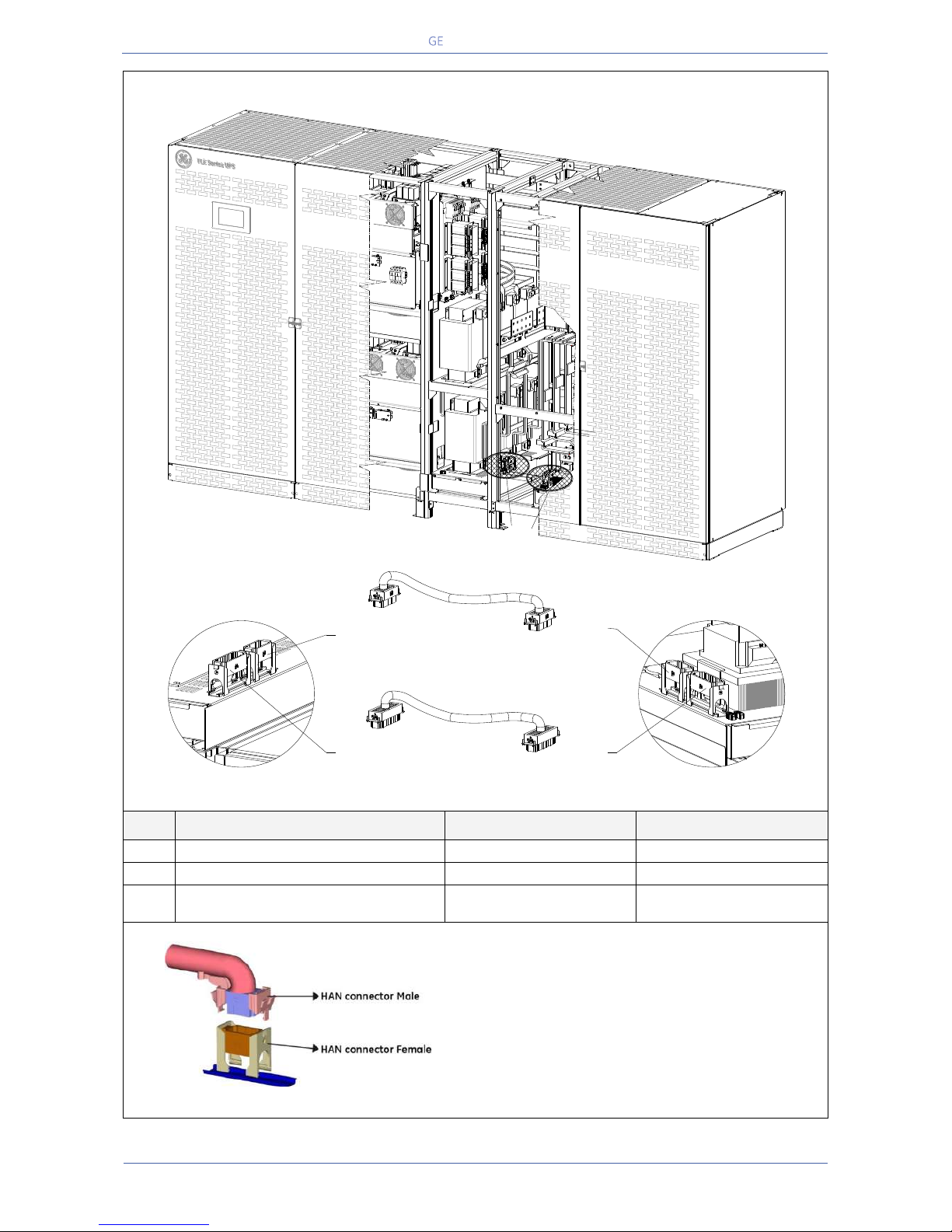
Critical Power
Modifications reserved
Page 44/146
GE_UPS_OPM_TLE_SCE_M60_M80_1GB_V020.docx
User Manual TLE Series 600 & 800 CE S1
TLE Series 800 - Control cables interconnection
Fig. 5.7.3-4 TLE Series 800 – Control cables interconnection
Pos.
Connection
From
To
1
XD1 – HAN Connector male (46 poles)
“Power Section cabinet”
“In/Out Section cabinet”
2
XD2 - HAN Connector male (32 poles)
“Power Section cabinet”
“In/Out Section cabinet”
3
XTR2A - Connector
“Power Section cabinet”
“In/Out Section cabinet”
XTR2 Connector
Fig. 5.7.3-5 Connection of hearting connectors (HAN connectors)
NOTE: All these connections must be performed by
QUALIFIED SERVICE PERSONNEL only.
Proper dressing needs to be done for each cable
assembly in order to reduce the stress.
All the cables must be sufficiently (at least 10cm/4")
away from all live parts.
Cable binders used to support the wiring must NOT be
overly tightened.
In/Out Section cabinet
XD1
(46 poles)
Power Section cabinet
XD2
(32 poles)
XD1
(46 poles)
XD2
(32 poles)
XD1 Connector (46 poles)
XD2 Connector (32 poles)
1 2
TLES_800_S1_UPS connection cabinets_GE_03GB
1
2
Page 45
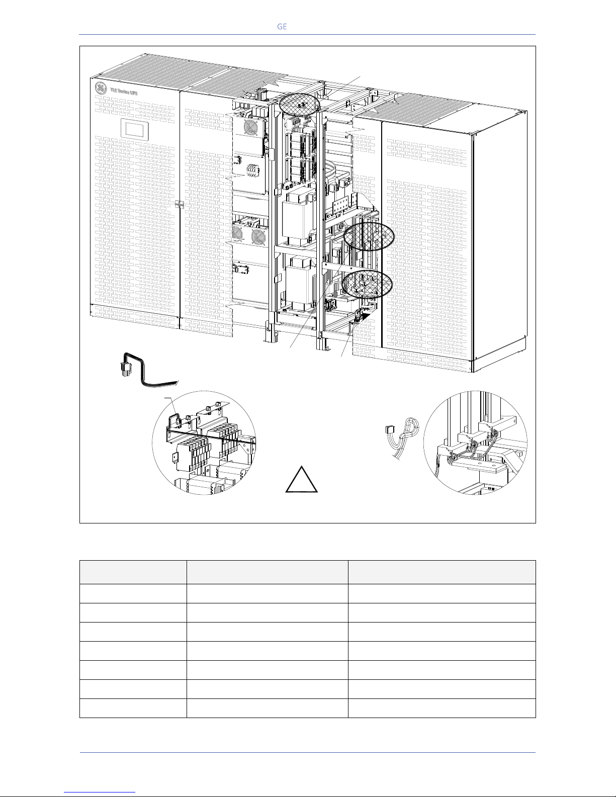
Critical Power
Modifications reserved
Page 45/146
GE_UPS_OPM_TLE_SCE_M60_M80_1GB_V020.docx
User Manual TLE Series 600 & 800 CE S1
Fig. 5.7.3-6 TLE Series 800 – Control cables interconnection
Connection
From (already connected)
To
XTR2A - Connector
“In/Out Section cabinet”
“Power Section cabinet” - XTR2 Connector
H9
“Power Section cabinet”
“In/Out Section cabinet” – H9 LEM
H10
“Power Section cabinet”
“In/Out Section cabinet” – H10 LEM
H11
“Power Section cabinet”
“In/Out Section cabinet” – H11 LEM
H13
“Power Section cabinet”
“In/Out Section cabinet” – H13 LEM
H14
“Power Section cabinet”
“In/Out Section cabinet” – H14 LEM
H15
“Power Section cabinet”
“In/Out Section cabinet” – H15 LEM
XTR2A
XTR2A
XTR2A connector
H9-10-11
H13-14-15
The cables must be fixed
and do not touch
the bus bars
!
In/Out Section cabinet
Power Section cabinet
TLES_800_S1_UPS connection cabinets_GE_04GB
H13-14-15
H9-10-11
Page 46
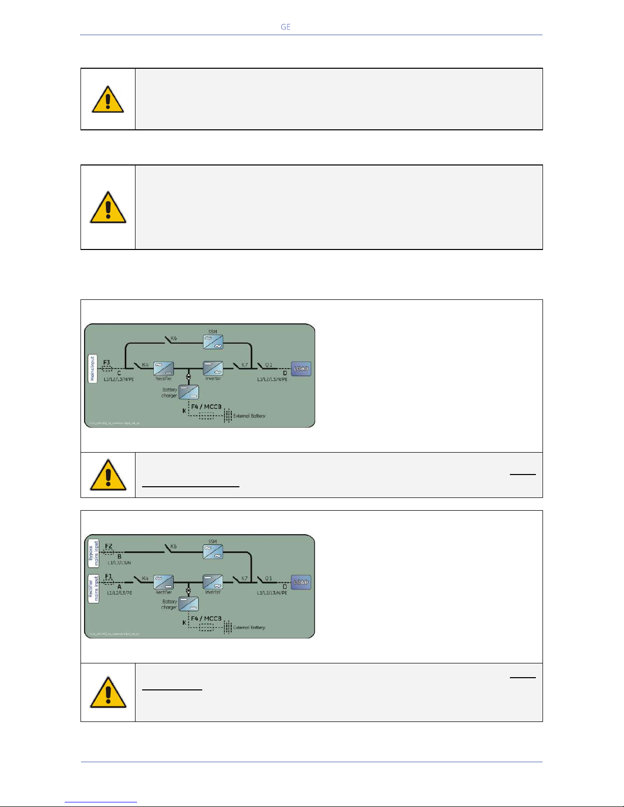
Critical Power
Modifications reserved
Page 46/146
GE_UPS_OPM_TLE_SCE_M60_M80_1GB_V020.docx
User Manual TLE Series 600 & 800 CE S1
5.8 ELECTRICAL WIRING
WARNING !
UPS installation and connection must be performed by QUALIFIED SERVICE
PERSONNEL only.
Refer to the “Safety prescriptions - Installation” described on Section 1.
5.8.1 Mains input connection
NOTE !
Ensure that the AC and DC external isolators are OFF and locked out to prevent their
inadvertent operation.
Do not apply power to the equipment prior to the commissioning by a QUALIFIED
SERVICE ENGINEER.
Before any other input connection, connect and check the earthing wire.
The Mains input power connection can be common or separate for Bypass supply and Rectifier input,
depending on the electrical system provided by the customer.
Common mains input Rectifier & Bypass
Fig. 5.8.1-1 Common mains input Rectifier & Bypass
The same power source is to be used for both
Bypass supply and Rectifier input (input F3).
Bear in mind that when the Mains fuses are
opened there is a supply failure to the Rectifier
as well as to the Automatic Bypass and
Manual Bypass switch (only if provided by
customer).
In this case, the interconnection links BR1, BR2 and BR3 on the input bus bars MUST
REMAIN CONNECTED. See Fig. 5.9.1-1 and 5.9.3-1.
Separate mains input Rectifier & Bypass
Fig. 5.8.1-2 Separate mains input Rectifier & Bypass
The Bypass and Rectifier use different power
sources (F1 and F2 inputs).
In this case, when the Rectifier-input fuses are
opened, the Automatic Bypass and the
Manual Bypass (only if provided by customer)
are supplied by the other connection.
In this case, the interconnection links BR1, BR2 and BR3 on the input bus bars MUST
BE REMOVED. See Fig. 5.9.2-2 and 5.9.4-2.
Connect a single input Neutral to Bypass Mains (inside the UPS, common Neutral for
Bypass and Rectifier).
Page 47
Critical Power
Modifications reserved
Page 47/146
GE_UPS_OPM_TLE_SCE_M60_M80_1GB_V020.docx
User Manual TLE Series 600 & 800 CE S1
5.8.2 Input/output over current protection and wire sizing
NOTE !
The UPS is designed for TN System.
The input neutral shall be grounded at source and shall never be disconnected.
4 pole breaker shall not be used at the UPS input (see also IEC 60364, IEC 61140, IEC
61557).
The cabling of the UPS system has to be sized according to the UPS power rating.
Exceptions are only allowed to suit local prescriptions.
Sizing of circuit breakers, fuses and cables for Mains Input, output load and battery must meet the
requirements of local and national electrical codes.
Before connecting the UPS, verify that the mains voltage and frequency, the output load voltage and
frequency and battery data (cells number, floating voltage, autonomy) are according to the required
data.
The protection of the UPS mains input must be exclusively with 3 pole breakers.
Disconnection of the Neutral is not permitted.
The UPS needs the connection of the Neutral to the input, to guarantee the function in TN mode
(Neutral-Earth).
Caution when using four-pole circuit breakers as protection to the UPS Load.
A potential problem exists for situations with non-linear Loads, causing the neutral current to be higher
than the phase current.
Avoid to run the input cables in parallel with the output cables to prevent them from noise induction.
The three-phase Mains power supply must be symmetrical with respect to earth, due to the existence of
voltage surge protection devices inside the UPS.
The connection of the Battery to the UPS must be protected with fuses or similar devices according to
technical specifications and in accordance with local standards.
NOTE !
If you use ELCB breakers to protect the input connections, consider the high leakage
current towards the earth generated by the noise suppression capacitors.
If these ELCB breakers are strictly necessary, we suggest to use the largest type
suitable for non-linear current and for delayed operation.
To ensure the circuit selectivity in case of short- circuit in the load equipment, special care must be
taken in choosing the fuse or circuit breaker ratings installed in the output distribution circuits.
Due to the relatively low short-circuit capability of the UPS Inverter, a short-circuit in the Load will cause
an immediate transfer to Mains.
The largest fuse in the output distribution should be at least 1.6 time smaller than the fuses supplying
the bypass line.
If circuit selectivity is required while the Load is fed from the Inverter (Bypass Mains not available), the
largest fuse or circuit breaker should be rated at no more than 20% of the UPS output current rating.
Page 48
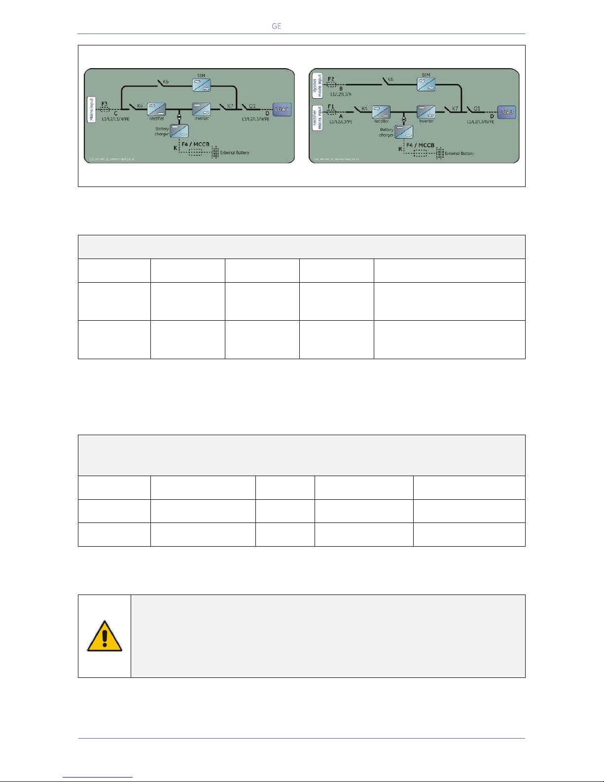
Critical Power
Modifications reserved
Page 48/146
GE_UPS_OPM_TLE_SCE_M60_M80_1GB_V020.docx
User Manual TLE Series 600 & 800 CE S1
Common mains input Rectifier & Bypass
Separate mains input Rectifier & Bypass
Fig. 5.8.2-1 Common mains input Rectifier & Bypass
Fig. 5.8.2-2 Separate mains input Rectifier & Bypass
Fuses AgL / circuit breakers (3x380/220V, 3x400/230V, 3x415/240V)
UPS model
F1
F2
F3
F4 / MCCB
1
)
TLE Series 600
3 x 1000A
3 x 1000A
3 x 1000A
1600A
2 x FKN36NT100SF / 800A 2)
TLE Series 800
3 x 1250A
3 x 1250A
3 x 1250A
2000A
2 x FKN36NT125SF / 1000A 2)
1)
MCCB: can be supplied by GE
2)
setting value: Ir – overload protection. Two parallel battery strings.
Cables section (mm2) A, B, C, D, K / IEC 60950-1
Local Standard and cables installation disposal shall be applied
UPS model
A B C &D
K
TLE Series 600
3 x (3x185) + 2x150
4 x (3x185)
4 x (3x185) + 2x150
2 x [2x(2x240) + 240]
TLE Series 800
3 x (3x240) + 2x185
4 x (3x240)
4 x (3x240) + 2x185
2 x [2x(4x120) + 2x120]
NOTE !
The delivery and installation of fuses and input/output connections of the UPS are at
the customer’s expense, unless agreed otherwise.
Connect a single input Neutral to Bypass Mains (inside the UPS, common Neutral for
Bypass and Rectifier).
Page 49
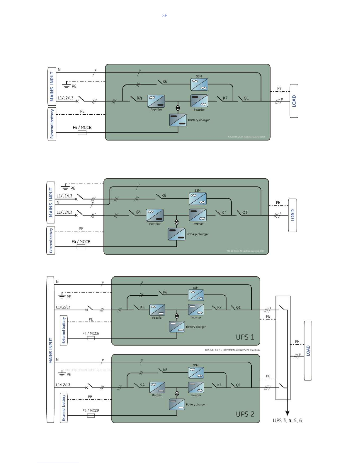
Critical Power
Modifications reserved
Page 49/146
GE_UPS_OPM_TLE_SCE_M60_M80_1GB_V020.docx
User Manual TLE Series 600 & 800 CE S1
5.8.3 Installation requirements
Typical examples for the connection of the TLE Series 600 & 800.
Single UPS with Common Mains Input for Rectifier & Bypass
Single UPS with Separate Mains Input for Rectifier & Bypass
(Connect a single input Neutral to Bypass Mains (inside the UPS, common Neutral for Bypass and
Rectifier).
UPS Parallel System with Common Mains Input Rectifier & Bypass
Page 50
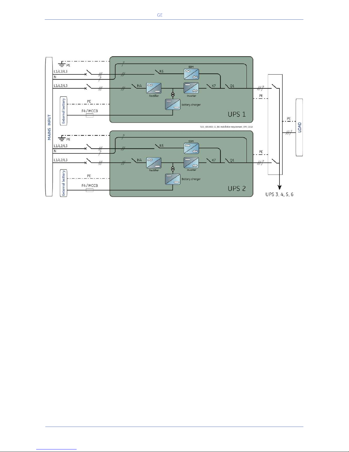
Critical Power
Modifications reserved
Page 50/146
GE_UPS_OPM_TLE_SCE_M60_M80_1GB_V020.docx
User Manual TLE Series 600 & 800 CE S1
UPS Parallel System with Separate Mains Input for Rectifier & Bypass
(Connect a single input Neutral to Bypass Mains (inside the UPS, common Neutral for Bypass and
Rectifier).
Page 51
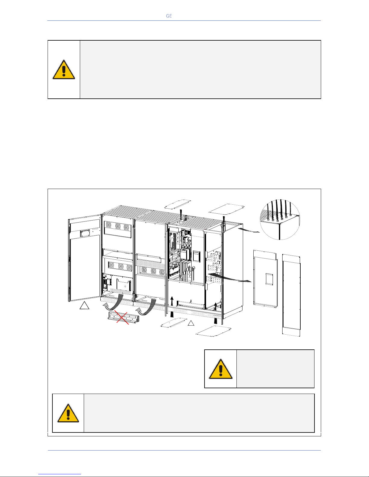
Critical Power
Modifications reserved
Page 51/146
GE_UPS_OPM_TLE_SCE_M60_M80_1GB_V020.docx
User Manual TLE Series 600 & 800 CE S1
5.9 ELECTRICAL CONNECTION
WARNING !
UPS installation and connection must be performed by QUALIFIED SERVICE
PERSONNEL only.
Refer to the “Safety prescriptions - Installation” described on Chapter 1.
In case of UPS equipped with options or customized parts not covered by this
manual, please consult the appropriate technical documentation before proceeding
with electrical connections.
Carefully read the following recommendations before proceeding:
Ensure that the AC and DC external isolators are Off, and prevent their inadverted operation.
Do not close any external isolators prior to the commissioning of the equipment.
The input/output cables must be put in order and fixed, taking care to avoid risk of short-circuit
between different poles.
The earthing and neutral connection of the electrical system must be in accordance with local
regulations.
In case of additional cabinets containing input/ output transformers, etc, the earth must be
connected to the UPS main earth.
Once the power cables have been connected, re-install the internal safety shields and close the
cabinets by re-installing all external panels.
TLE Series 600 Access to the bus bars for the cable connections
Fig. 5.9-1 TLE Series 600 - Access to connection bus bars
To access Input, Output and Battery connections
proceed as follows:
Remove the front protection panels “A & B”.
Top entry cables: remove the plates “C & D”.
Bottom entry cables: remove the plates “E & F”.
NOTE !
For UPS correct
operation, the Mains
Input phase rotation
must be clock-wise.
NOTE !
Drill the cover plate “C/D” appropriate holes for cable entry. See drawing “1” for
details.
The holes must be drilled with the cover plate “C/D/E/F” removed from the UPS
to avoid metal dust falling in the connection bars area.
TLES_600_S1_UPS connection_01GB
EPO
EPO
-
+
12
Q1
0 OFF
I ON
D
Top entry cables
Battery
C
Top entry cables
Mains input &
Load output
Bottom entry cables
Mains input & Load output
E
!
Please remove
the plates (C-D-E-F)
before drilling any wholes
Bottom entry cables
Battery
F
!
It's MANDATORY REMOVE
the two base reinforcement
See Chapter 5.4.1
A
B
1
Page 52
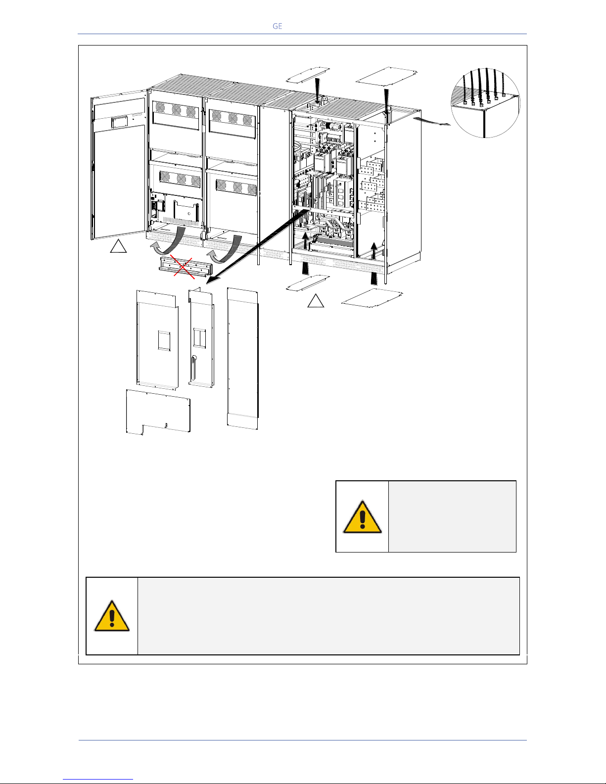
Critical Power
Modifications reserved
Page 52/146
GE_UPS_OPM_TLE_SCE_M60_M80_1GB_V020.docx
User Manual TLE Series 600 & 800 CE S1
TLE Series 800 - Access to the bus bars for the cable connections
Fig. 5.9-2 TLE Series 800 - Access to the bus bars for the cable connections
To access Input, Output and Battery connections
proceed as follows:
Remove the front protection panels “A, B, C, D”.
Top entry cables: remove the plates “E & F”.
Bottom entry cables: remove the plates “G & H”.
NOTE !
For UPS correct
operation, the input
utility phase rotation
must be clock-wise.
NOTE !
Drill the cover plate “E/F” appropriate holes for cable entry. See drawing “1” for
details.
The holes must be drilled with the cover plate “E/F/G/H” removed from the UPS to
avoid metal dust falling in the connection bars area.
E
Please remove
the plates (E-F-G-H) before
drilling any wholes
!
It's MANDATORY REMOVE
the two base reinforcement
See Chapter 4.4.1
F
Top entry cables
Battery
Top entry cables
Utility input & Load output
Bottom entry cables
Battery
Bottom entry cables
Utility input & Load output
G
H
TLES_800_S1_UPS connection_01GB
-
+
12
!
A
CB
D
1
Page 53
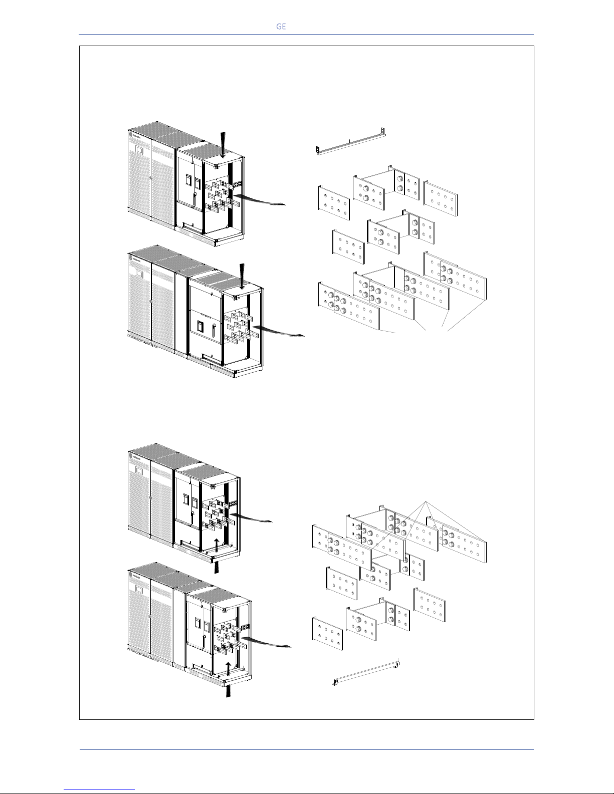
Critical Power
Modifications reserved
Page 53/146
GE_UPS_OPM_TLE_SCE_M60_M80_1GB_V020.docx
User Manual TLE Series 600 & 800 CE S1
TLE Series 600 & 800
Power connection bus bars configuration for the top cable entry or bottom cable entry
The configuration of the TLE Series 600 & 800 is with top cable entry as standard (see Fig. 5.9-3).
It is possible to configure the bus bars with bottom cable entry (see Fig. 5.9-4).
Fig. 5.9-3 TLE Series 600 & 800 – Power connection configuration bus bars with top cable entry (standard)
Power connection cables are connected to bus bars using M12 bolts.
The bolts of the connection cables must be tightened with a torque wrench at 60 Nm.
Fig. 5.9-4 TLE Series 600 & 800 - Power connection configuration bus bars with bottom cable entry
Position of the bus bars for
cables input from the top of the UPS
Q1
Top entry cables
Utility input & Load output
Load
L3
Load
L2
Load
L1
BR3
BR2
BR1
L3-2
L2-2
L1-2
L3-1
L2-1
L1-1
N
N
TLE Series 800
TLE Series 600
Q1
Top entry cables
Utility input & Load output
A
Position of the bus bars for
cables input from the bottom of the UPS
Load
L3
Load
L2
Load
L1
BR3
BR2
L3-2
L2-2
L3-1
L2-1
N
BR1
L1-2
L1-1
N
TLE Series 800
TLE Series 600
A
Q1
A
Bottom entry cables
Utility input & Load output
Bottom entry cables
Utility input & Load output
Q1
A
Page 54
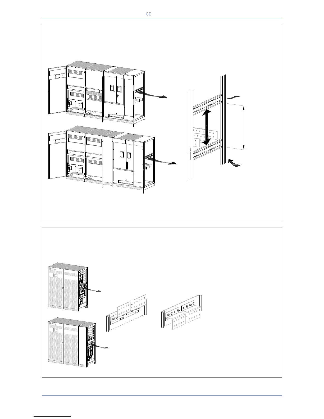
Critical Power
Modifications reserved
Page 54/146
GE_UPS_OPM_TLE_SCE_M60_M80_1GB_V020.docx
User Manual TLE Series 600 & 800 CE S1
TLE Series 600 & 800
PE-Ground connection bus bar configuration for the top cable entry or bottom cable entry
The configuration of the TLE Series 600 & 800 is with top cable entry as standard.
It is possible to configure the bus bar with bottom cable entry (see Fig. 5.9-5).
Fig. 5.9-5 TLE Series 600 & 800 – PE-Ground connection configuration bus bar with top or bottom cable entry
PE-Ground connection cables are connected to bus bars using M12 bolts.
The bolts of the connection cables must be tightened with a torque wrench at 60 Nm.
TLE Series 600 & 800
Battery connection bus bars configuration for the top cable entry or bottom cable entry
The configuration of the TLE Series 600 & 800 is with top cable entry as standard.
It is possible to configure the bus bars with bottom cable entry (see Fig. 5.9-6).
Battery connection cables
are connected to bus bars
using M10 bolts.
The bolts of the connection
cables must be tightened
with a torque wrench at 40
Nm.
Fig. 5.9-6 TLE Series 600 & 800 – Battery connection configuration bus bars with top or bottom cable entry
TLES_600-800_S1_UPS connection PE_Top & Bottom_01GB
-
+
12
Q1
0 OFF
I ON
Position of the
PE-Ground bus bar
for cables input from
the top of the UPS
450 mm
17.72 "
TLE Series 800
TLE Series 600
Position of the
PE-Ground bus bar
for cables input from
the bottom of the UPS
-
+
12
Q1
0 OFF
I ON
TLES_600-800_S1_UPS connection battery_Top & Bottom_01GB
+
_
+
_
TLE Series 800
TLE Series 600
Position of the bus bars for
cables input from the bottom of the UPS
Power Section cabinet
Position of the bus bars for
cables input from the top of the UPS
Power Section cabinet
Page 55
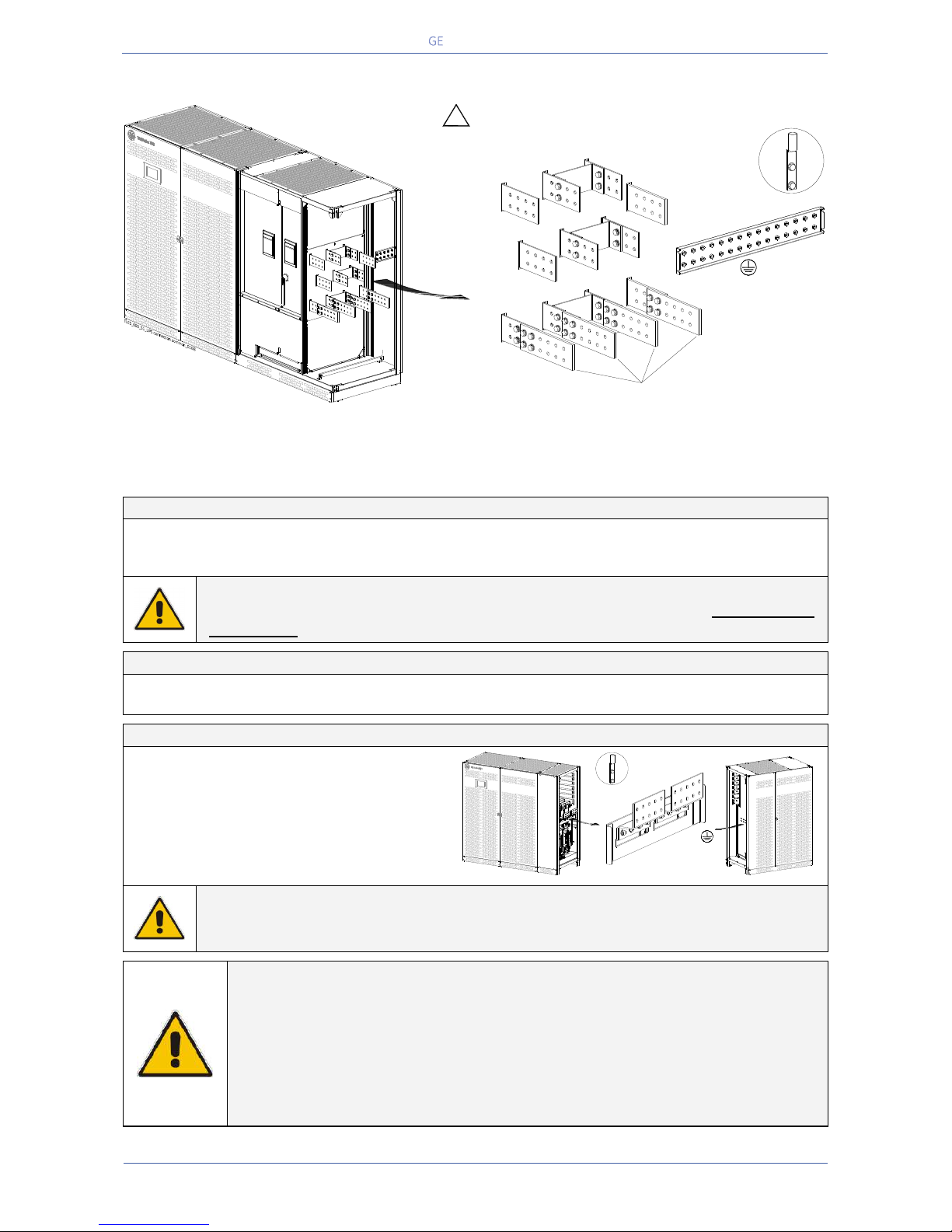
Critical Power
Modifications reserved
Page 55/146
GE_UPS_OPM_TLE_SCE_M60_M80_1GB_V020.docx
User Manual TLE Series 600 & 800 CE S1
5.9.1 TLE Series 600 - Power connection with Common Mains Input
Fig. 5.9.1-1 TLE Series 600 - Power connection with common Mains Input
Power connection cables are connected to bus bars using M12 bolts.
The bolts of the connection cables must be tightened with a torque wrench at 60 Nm.
Fix the cables on accessory “A” with the enclosed cable ties.
Common Mains Input - Rectifier / Bypass
L1-1
Rectifier + Bypass Phase L1
L2-1
Rectifier + Bypass Phase L2
N
Mains Neutral
L3-1
Rectifier + Bypass Phase L3
PE
Mains Ground
NOTE !
The interconnection links BR1, BR2 and BR3 on the input bus bars MUST REMAIN
CONNECTED (see Fig. 5.9.1-1).
Output Load
L1
Load phase L1
L2
Load phase L2
L3
Load phase L3
N
Load Neutral
PE
Load Ground
External Battery connection
+
Positive pole of the battery
-
Negative pole of the battery
PE
Battery cabinet ground
Bolt Size / Torque: M10 / 40 Nm
DANGER !
Before closing the “External Battery Fuses”, verify for correct polarity of the External
Battery connection.
NOTE !
To meet standards concerning electromagnetic compliance, the connection
between the UPS and external Battery must be done by using a shielded cable or
suitable shielded (steel) conduit!
This UPS is only designed to operate in a wye-configured electrical system with a
solidly grounded neutral.
If the UPS is equipped with an input bypass transformer, the secondary of the
transformer must be wye-configured with neutral solidly grounded.
Position of the bus bars for
cables input from the top of the UPS (see Section 5.9)
Load
L3
Load
L2
Load
L1
BR3
BR2
BR1
INTERCONNECTIONS LINKS
BR1, BR2 and BR3
MUST REMAIN CONNECTED
PE
!
L2-1
L3-1
N
Mains Neutral
Load Neutral
N
Mains Neutral
Load Neutral
1
Rectifier
Mains
Q1
Typical installation
using common NEMA
two hole lugs
A
L1-1
Typical installation
using common NEMA
two hole lugs
TLES_800_S1_UPS connection battery_01GB
Power Section cabinet
+
_
In/Out Section cabinet
PE
Page 56
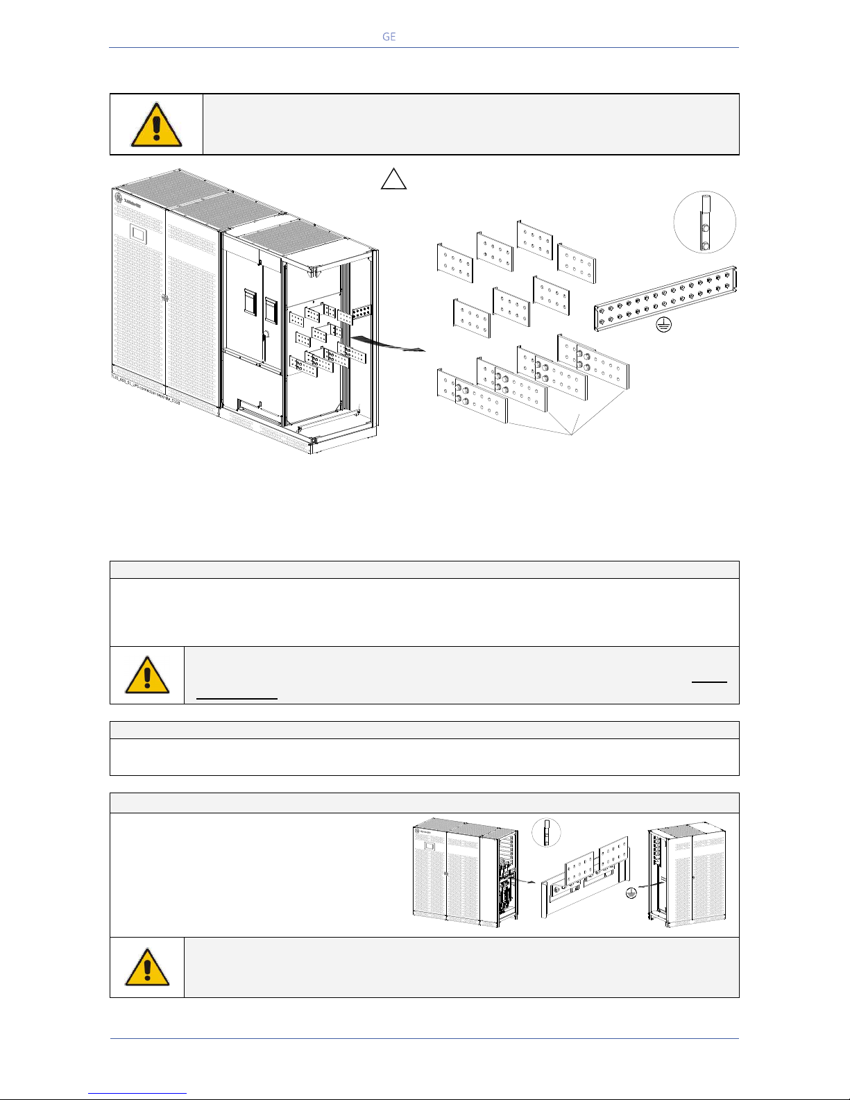
Critical Power
Modifications reserved
Page 56/146
GE_UPS_OPM_TLE_SCE_M60_M80_1GB_V020.docx
User Manual TLE Series 600 & 800 CE S1
5.9.2 TLE Series 600 - Power connection with Separate Mains Input
NOTE !
Connect a single input Neutral to Bypass Mains (inside the UPS, common Neutral
for Bypass and Rectifier).
Fig. 5.9.2-1 TLE Series 600 - Power connection with Separate Mains Input
Power connection cables are connected to bus bars using M12 bolts.
The bolts of the connection cables must be tightened with a torque wrench at 60 Nm.
Fix the cables on accessory “A” with the enclosed cable ties.
Separate Mains Input - Rectifier / Bypass
L1-1
Rectifier phase L1
L1-2
Bypass phase L1
L2-1
Rectifier phase L2
L2-2
Bypass phase L2
L3-1
Rectifier phase L3
L3-2
Bypass phase L3
PE
Mains Ground
N
Mains Neutral (Bypass)
NOTE !
In this case, the interconnection links BR1, BR2 and BR3 on the input bus bars MUST
BE REMOVED. See Fig. 5.9.2-2.
Output Load
L1
Load phase L1
L2
Load phase L2
L3
Load phase L3
N
Load Neutral
PE
Load Ground
External Battery connection
+
Positive pole of the battery
-
Negative pole of the battery
PE
Battery cabinet ground
Bolt Size / Torque: M10 / 40 Nm
DANGER !
Before closing the “External Battery Fuses”, verify for correct polarity of the External
Battery connection.
PE
!
Q1
Position of the bus bars for
cables input from the top of the UPS (see Section 5.9)
Load
L3
Load
L2
Load
L1
L1-2
L2-2
L3-2
N
Mains Neutral
Load Neutral
N
Mains Neutral
Load Neutral
1
Rectifier
Mains
2
Bypass
Mains
INTERCONNECTIONS LINKS
BR1, BR2 and BR3
MUST BE REMOVED
(see Fig 5.9.2-2)
L1-1
L2-1
L3-1
Typical installation
using common NEMA
two hole lugs
A
Typical installation
using common NEMA
two hole lugs
TLES_800_S1_UPS connection battery_01GB
Power Section cabinet
+
_
In/Out Section cabinet
PE
Page 57
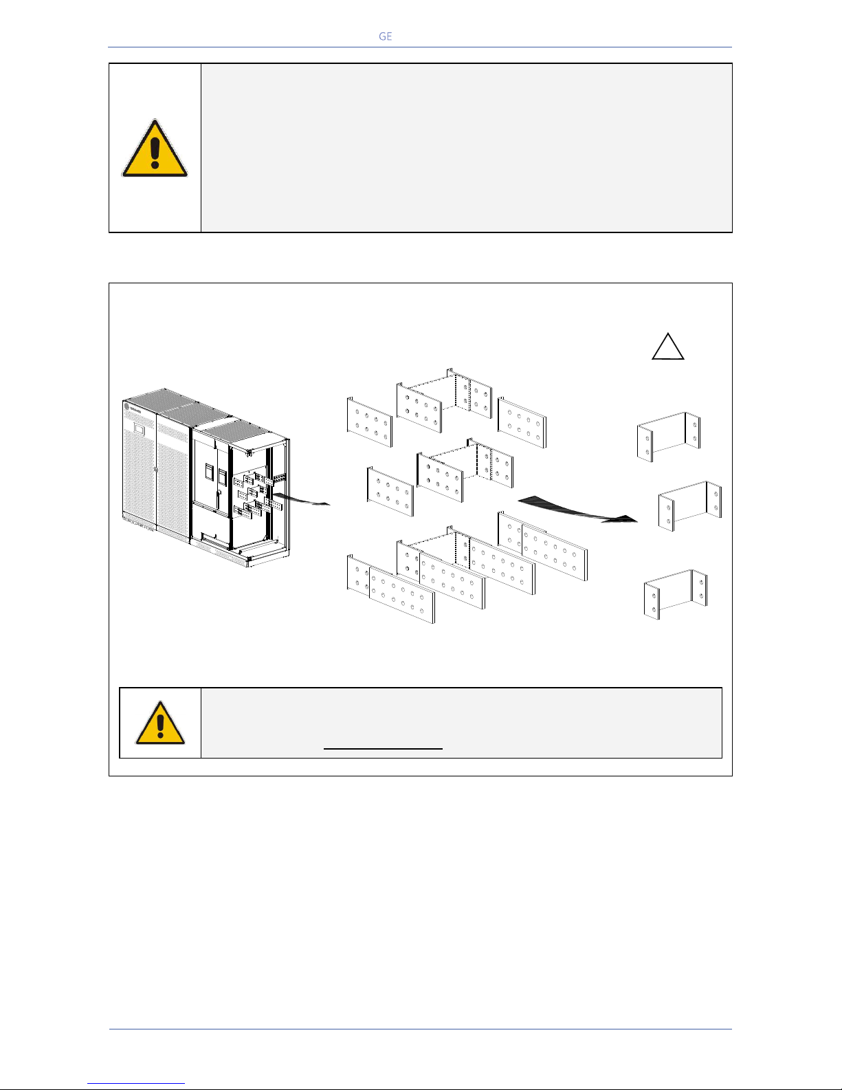
Critical Power
Modifications reserved
Page 57/146
GE_UPS_OPM_TLE_SCE_M60_M80_1GB_V020.docx
User Manual TLE Series 600 & 800 CE S1
NOTE !
To meet standards concerning electromagnetic compliance, the connection
between the UPS and external Battery must be done by using a shielded cable or
suitable shielded (steel) conduit!
This UPS is only designed to operate in a wye-configured electrical system with a
solidly grounded neutral.
If the UPS is equipped with an input bypass transformer, the secondary of the
transformer must be wye-configured with neutral solidly grounded.
Installation notices in case of power connection with Separate Mains Input
Fig. 5.9.2-2 TLE Series 600 - Interconnection links BR1, BR2 and BR3
NOTE !
For separate Bypass and Rectifier input configuration, the interconnection links
BR1, BR2 and BR3 MUST BE REMOVED (see Fig. 5.9.2-2).
INTERCONNECTIONS LINKS
BR1, BR2 and BR3
MUST BE REMOVED
!
1
Rectifier
Mains
BR3
2
Bypass
Mains
BR2
BR1
Load
L3
Load
L2
Load
L1
BR3
BR2
BR1
L2-2
L3-2
N
Mains Neutral
Load Neutral
N
Mains Neutral
Load Neutral
L2-1
L3-1
L1-2
L1-1
Q1
A
Page 58
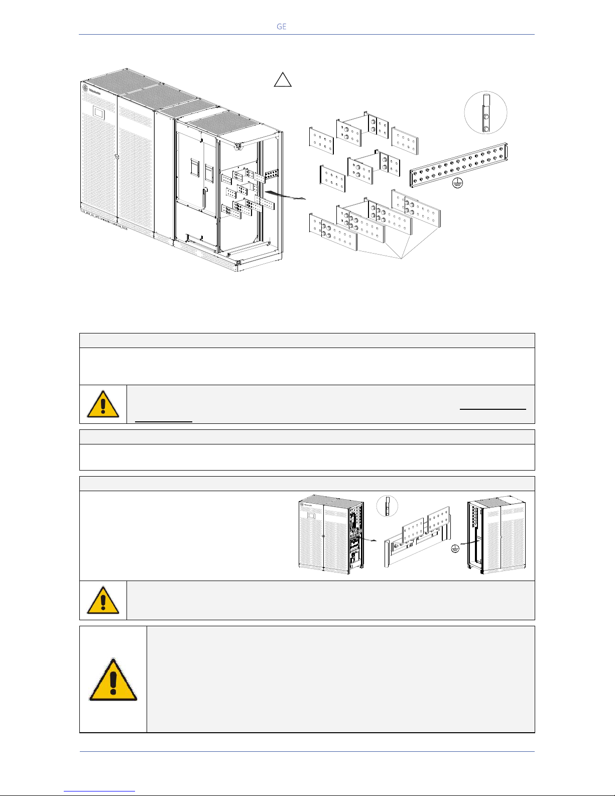
Critical Power
Modifications reserved
Page 58/146
GE_UPS_OPM_TLE_SCE_M60_M80_1GB_V020.docx
User Manual TLE Series 600 & 800 CE S1
5.9.3 TLE Series 800 - Power connection with Common Mains Input
Fig. 5.9.3-1 TLE Series 800 - Power connection with Common Mains Input
Power connection cables are connected to bus bars using M12 bolts.
The bolts of the connection cables must be tightened with a torque wrench at 60 Nm.
Fix the cables on accessory “A” with the enclosed cable ties.
Common Mains Input - Rectifier / Bypass
L1-1
Rectifier + Bypass Phase L1
L2-1
Rectifier + Bypass Phase L2
N
Mains Neutral
L3-1
Rectifier + Bypass Phase L3
PE
Mains Ground
NOTE !
The interconnection links BR1, BR2 and BR3 on the input bus bars MUST REMAIN
CONNECTED (see Fig. 5.9.3-1).
Output Load
L1
Load phase L1
L2
Load phase L2
L3
Load phase L3
N
Load Neutral
PE
Load Ground
External Battery connection
+
Positive pole of the battery
-
Negative pole of the battery
PE
Battery cabinet ground
Bolt Size / Torque: M10 / 40 Nm
DANGER !
Before closing the “External Battery Fuses”, verify for correct polarity of the External
Battery connection.
NOTE !
To meet standards concerning electromagnetic compliance, the connection
between the UPS and external Battery must be done by using a shielded cable or
suitable shielded (steel) conduit!
This UPS is only designed to operate in a wye-configured electrical system with a
solidly grounded neutral.
If the UPS is equipped with an input bypass transformer, the secondary of the
transformer must be wye-configured with neutral solidly grounded.
Position of the bus bars for
cables input from the top of the UPS (see Section 5.9)
Q1
Load
L3
Load
L2
Load
L1
BR3
BR2
BR1
INTERCONNECTIONS LINKS
BR1, BR2 and BR3
MUST REMAIN CONNECTED
PE
!
L2-1
L3-1
N
Mains Neutral
Load Neutral
N
Mains Neutral
Load Neutral
1
Rectifier
Mains
Typical installation
using common NEMA
two hole lugs
A
L1-1
Typical installation
using common NEMA
two hole lugs
+
_
PE
TLES_600_S1_UPS connection battery_01GB
Power Section cabinet
In/Out Section cabinet
Page 59
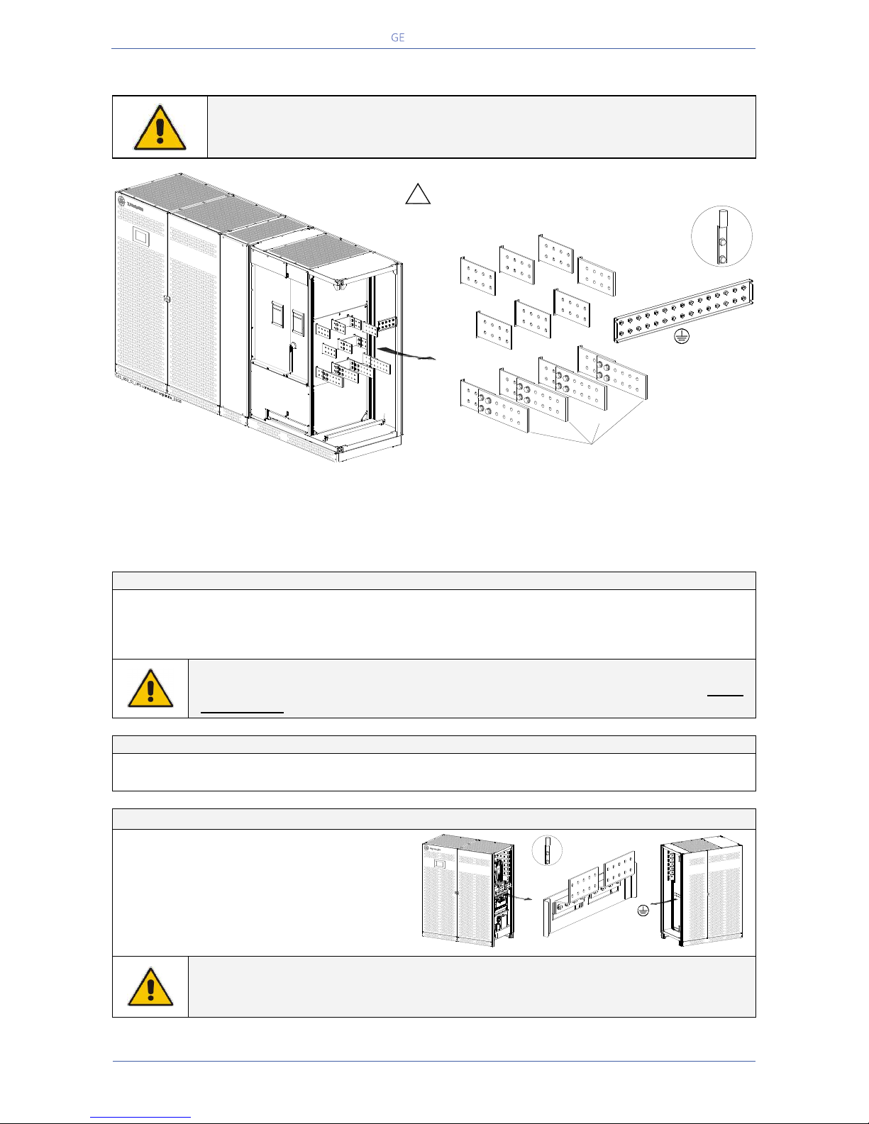
Critical Power
Modifications reserved
Page 59/146
GE_UPS_OPM_TLE_SCE_M60_M80_1GB_V020.docx
User Manual TLE Series 600 & 800 CE S1
5.9.4 TLE Series 800 - Power connection with Separate Mains Input
NOTE !
Connect a single input Neutral to Bypass Mains (inside the UPS, common Neutral
for Bypass and Rectifier).
Fig. 5.9.4-1 TLE Series 800 - Power connection with Separate Mains Input
Power connection cables are connected to bus bars using M12 bolts.
The bolts of the connection cables must be tightened with a torque wrench at 60 Nm.
Fix the cables on accessory “A” with the enclosed cable ties.
Separate Mains Input - Rectifier / Bypass
L1-1
Rectifier phase L1
L1-2
Bypass phase L1
L2-1
Rectifier phase L2
L2-2
Bypass phase L2
L3-1
Rectifier phase L3
L3-2
Bypass phase L3
PE
Mains Ground
N
Mains Neutral (Bypass)
NOTE !
In this case, the interconnection links BR1, BR2 and BR3 on the input bus bars MUST
BE REMOVED. See Fig. 5.9.4-2.
Output Load
L1
Load phase L1
L2
Load phase L2
L3
Load phase L3
N
Load Neutral
PE
Load Ground
External Battery connection
+
Positive pole of the battery
-
Negative pole of the battery
PE
Battery cabinet ground
Bolt Size / Torque: M10 / 40 Nm
DANGER !
Before closing the “External Battery Fuses”, verify for correct polarity of the External
Battery connection.
PE
!
Position of the bus bars for
cables input from the top of the UPS (see Section 5.9)
Load
L3
Load
L2
Load
L1
L1-2
L2-2
L3-2
N
Mains Neutral
Load Neutral
N
Mains Neutral
Load Neutral
1
Rectifier
Mains
2
Bypass
Mains
INTERCONNECTIONS LINKS
BR1, BR2 and BR3
MUST BE REMOVED
(see Fig 5.9.4-2)
L1-1
L2-1
L3-1
Typical installation
using common NEMA
two hole lugs
Q1
A
Typical installation
using common NEMA
two hole lugs
+
_
PE
TLES_600_S1_UPS connection battery_01GB
Power Section cabinet
In/Out Section cabinet
Page 60
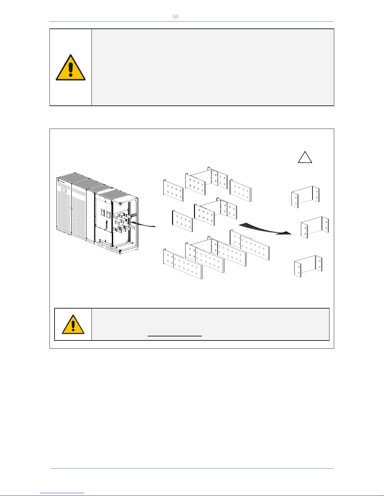
Critical Power
Modifications reserved
Page 60/146
GE_UPS_OPM_TLE_SCE_M60_M80_1GB_V020.docx
User Manual TLE Series 600 & 800 CE S1
NOTE !
To meet standards concerning electromagnetic compliance, the connection
between the UPS and external Battery must be done by using a shielded cable or
suitable shielded (steel) conduit!
This UPS is only designed to operate in a wye-configured electrical system with a
solidly grounded neutral.
If the UPS is equipped with an input bypass transformer, the secondary of the
transformer must be wye-configured with neutral solidly grounded.
Installation notices in case of power connection with Separate Mains Input
Fig. 5.9.4-2 TLE Series 800 - Interconnection links BR1, BR2 and BR3
NOTE !
For separate Bypass and Rectifier input configuration, the interconnection links
BR1, BR2 and BR3 MUST BE REMOVED (see Fig. 5.9.4-2).
INTERCONNECTIONS LINKS
BR1, BR2 and BR3
MUST BE REMOVED
!
1
Rectifier
Mains
BR3
2
Bypass
Mains
BR2
BR1
Load
L3
Load
L2
Load
L1
BR3
BR2
BR1
L2-2
L3-2
N
Mains Neutral
Load Neutral
N
Mains Neutral
Load Neutral
L2-1
L3-1
L1-2
L1-1
Q1
A
Page 61
Critical Power
Modifications reserved
Page 61/146
GE_UPS_OPM_TLE_SCE_M60_M80_1GB_V020.docx
User Manual TLE Series 600 & 800 CE S1
5.9.5 Use of TLE Series 600 & 800 in eBoost™ Operation Mode
NOTE !
For systems intended to be operated in eBoost™ Operation Mode, the installation
shall be protected with suitable surge protection devices (SPDs) on the AC bus
feeding the UPSs.
Please contact your Service Centre for more information.
NOTE !
In eBoostTM Operation Mode the inverter output filter is placed in parallel with the
load, and combined with the load current it contributes to the UPS input
characteristic.
As the inverter output filter exhibits a predominantly capacitive characteristic, it
may provide some degree of reactive power compensation when combined with
lagging power factor loads.
Conversely, depending on the load type and level, the UPS input characteristic
may exhibit a leading power factor in eBoostTM Operation Mode.
Please contact your Service Centre for more information.
NOTE !
If an emergency generator set supplies the UPS in case of Mains Failure, and the
system is intended to be operated in eBoost™ Operation Mode, eBoost operation
shall be prevented during generator operation.
This can be accomplished by either installing a “GENERATOR ON” signal (refer to
Section 9.2.5) or an “eBoost/IEMi CONTROL” signal (refer to Section 9.2.7).
Please contact your Service Centre for more information.
Page 62
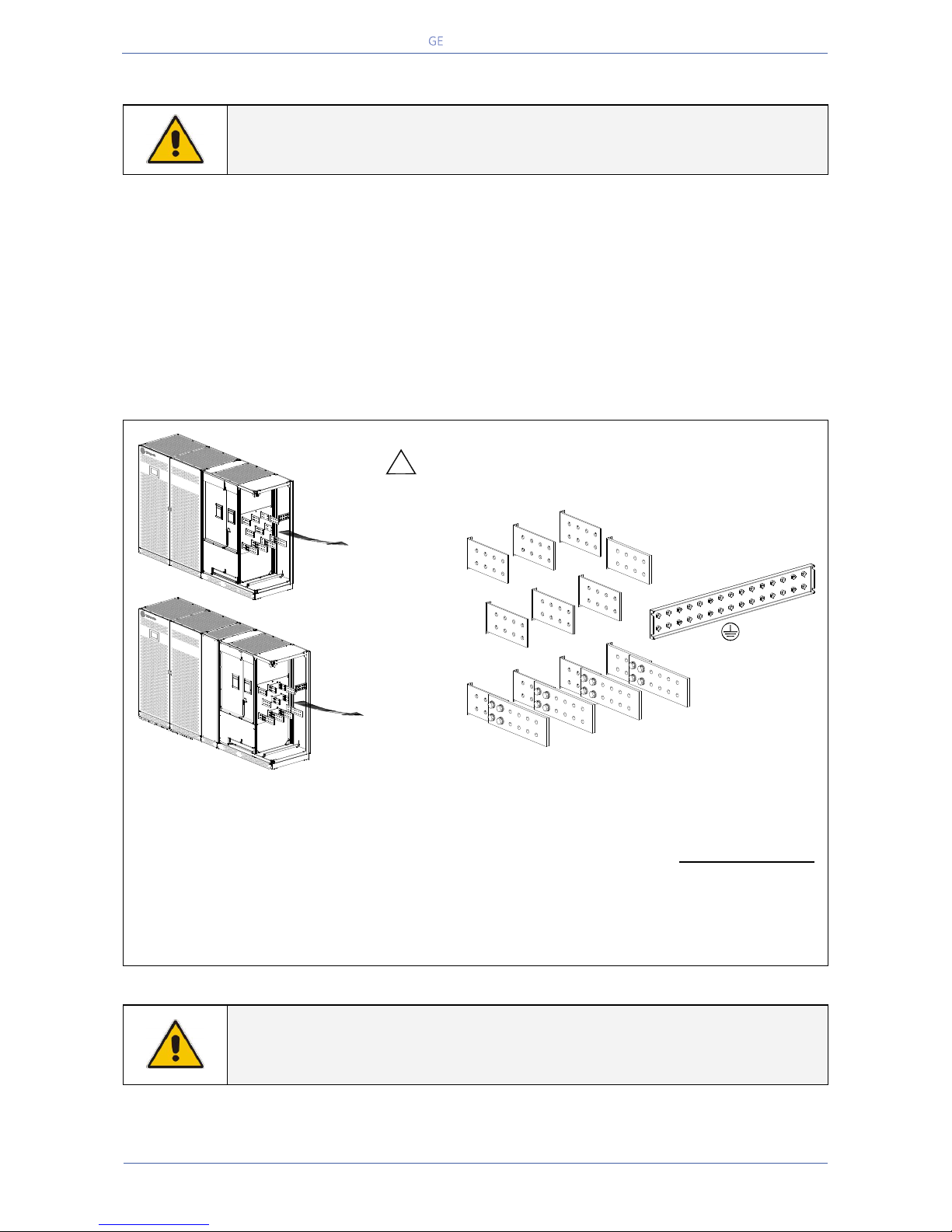
Critical Power
Modifications reserved
Page 62/146
GE_UPS_OPM_TLE_SCE_M60_M80_1GB_V020.docx
User Manual TLE Series 600 & 800 CE S1
5.9.6 Use of TLE Series 600 & 800 as Frequency Converter
NOTE !
The UPS needs the connection of the Neutral at the input Bus Bars.
When the TLE Series 600 & 800 is utilized for different output frequency compared to the input
frequency, the Automatic Bypass and Manual Bypass (only if provided by customer) functions are
disabled, therefore the Load cannot be transferred to Mains in case of overload, short circuit, or inverter
failure.
In situations where the UPS needs to be powered down for maintenance purposes, the critical Load
must also be powered down during this time.
When the set-up parameters of the UPS are set for frequency converter, the eBoost™ Operation Mode
is automatically disabled.
Fig. 5.9.6-1 TLE Series 600 & 800 - Power connection for UPS utilized as frequency converter
In order to avoid improper operation, only the Rectifier input should be powered (L1-1, L2-1 and L3-1
/ Fig. 5.9.1-1 and Fig. 5.9.3-1), therefore BR1, BR2 and BR3, on the input bus bars MUST BE REMOVED
(see Fig. 5.9.2-2 and Fig. 5.9.4-2).
Special care must be taken in choosing the Fuse Ratings installed in the output distribution (max.
20% of the UPS rated current).
Avoid high inrush current due to transformer magnetisation or motor starting.
NOTE !
At site only a QUALIFIED SERVICE ENGINEER may change a unit, initially delivered
as a Frequency Converter, into a normally operating “standard” UPS.
TLE Series 800
TLE Series 600
PE
!
L1-2
L2-2
L3-2
INTERCONNECTIONS LINKS
BR1, BR2 and BR3
MUST BE REMOVED
(see Fig 5.9.2-2 and 5.9.4.2)
L1-1
L2-1
L3-1
Q1
A
Q1
A
Load
L3
Load
L2
Load
L1
N
Mains Neutral
Load Neutral
N
Mains Neutral
Load Neutral
1
Rectifier
Mains
2
Bypass
Mains
Page 63
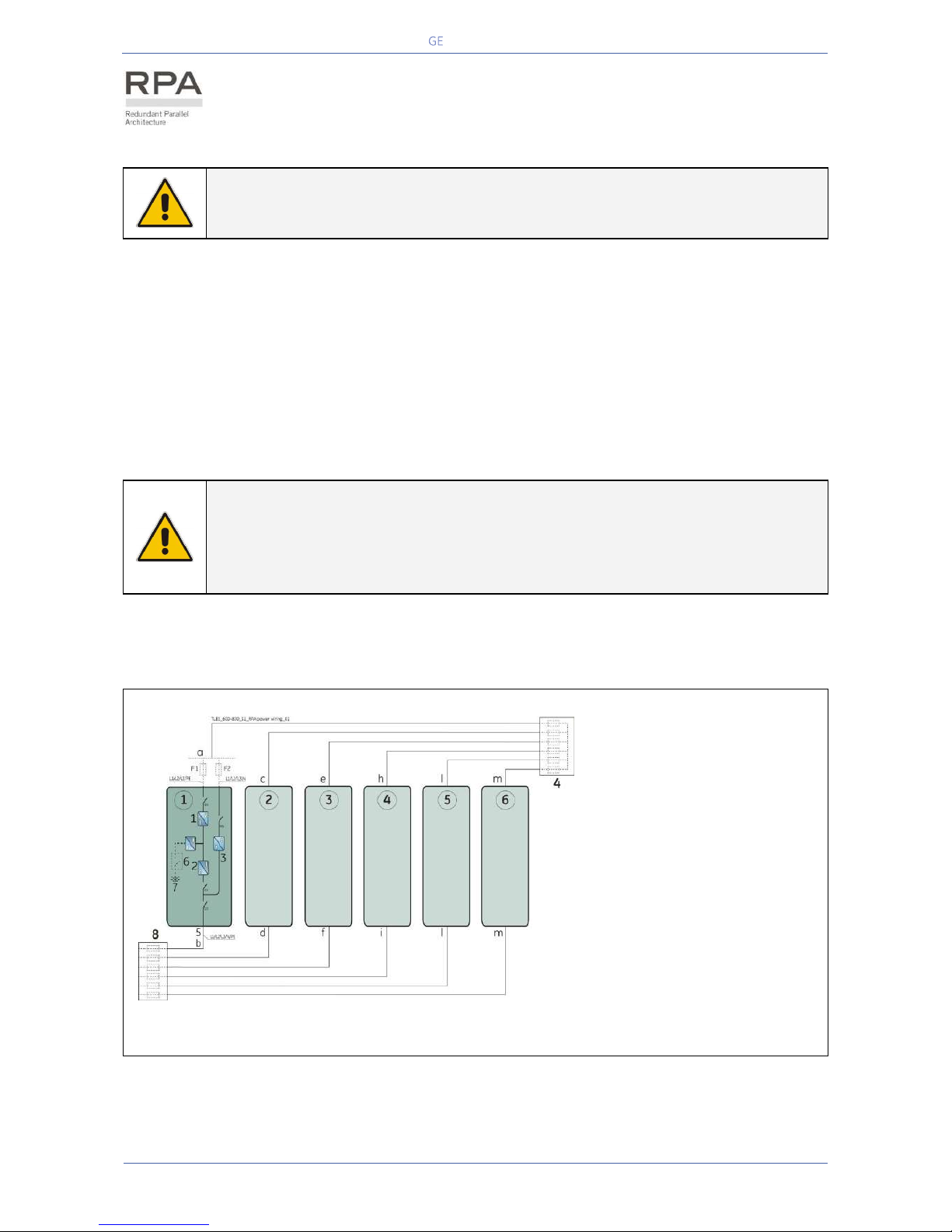
Critical Power
Modifications reserved
Page 63/146
GE_UPS_OPM_TLE_SCE_M60_M80_1GB_V020.docx
User Manual TLE Series 600 & 800 CE S1
5.10 RPA PARALLEL SYSTEM CONNECTION
WARNING !
This operation must be performed by trained personnel before the initial start-up
(ensure that the UPS installation is completely powered down).
5.10.1 Power wiring of parallel units
To guarantee good Load sharing between the units of a Parallel System, we recommend that the cable
length from the input distribution board (5) to the output distribution board (9) is equal for each unit (a+b
= c+d = e+f = g+h = i+l = m+n = o+p = q+r).
Tolerance: +/-10%.
The AC input power of the Bypass must be the same for all units of the Parallel System - no phase shift
allowed between units.
NOTE !
It is strongly recommended that no transformers, automatic circuit breakers or
fuses should be inserted between the unit’s output and the Load common bus bars.
However, it is recommended that a disconnection or isolation switch is installed in
order to totally isolate a unit if needed.
Verify that power wiring and control wiring run in separate conduits or cable trays.
The power wiring requires two separate conduits: one for input and one for output cables.
Fig. 5.10.1-1 Power wiring of RPA Parallel System
1
=
Rectifier
2
=
Inverter
3
=
Automatic Bypass
4
=
Mains Input Distribution
5
=
Unit Output Load
6
=
External Battery MCB
7
=
External Battery
8
=
Common bus bar and
Output Load Distribution
=
UPS number 1
=
UPS number 2
=
UPS number 3
=
UPS number 4
=
UPS number 5
=
UPS number 6
Page 64
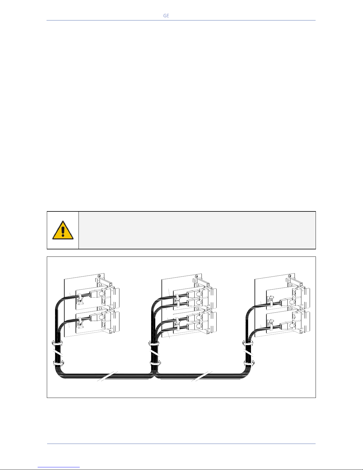
Critical Power
Modifications reserved
Page 64/146
GE_UPS_OPM_TLE_SCE_M60_M80_1GB_V020.docx
User Manual TLE Series 600 & 800 CE S1
5.10.2 Parallel control bus connection
In case of Parallel System, the communication between the units takes place through the Control Bus
Cables.
Each Parallel Unit contains the two boards “P13/P14 – IM0222 – Bus Interface Board” (mounted on top
of the board “P12 – IM0196 – RPA Board”) on which four connectors J1A - J2A and J1B - J2B are
allocated.
All the parallel units are connected to the same control bus.
This connection allows:
The microprocessors of each unit to communicate with each other.
The oscillators of each unit to be locked together.
The regulation loops to compare the output current of each unit in order to equally share the Load
current.
For increased reliability, this connection is made with redundant cables.
In this way, communication is maintained between units in case one of the control cables should fail or
be accidentally damaged or disconnected.
The standard length of the control bus cable between two parallel units is 12m / 40 ft.
The maximal overall length of bus connection, between the first and the last unit, should not exceed
90m / 295 ft.
Verify that control wiring run in an individual separate steel conduit.
NOTE !
Under no circumstance should the control bus cable connecting J1A - J2A (1/2/3/4/5)
and J1B - J2B (1/2/3/4/5) be connected or disconnected after the system has been
powered On.
Fig. 5.10.2-1 RPA System - Control bus connection
It is important to place the units in sequence of their assigned number.
A unit number from 1 to 6 is defined by the setting of parameters and displayed on the panel (1 to 6).
This number is also marked inside and outside the packaging.
J2
J1
J2
J1
B
A
J1A/1
J1B/1
J2
J1
J2
J1
J1A/1
J1B/2÷5
J1B/1
J1A/2÷5
J1A/1 + J1B/1
J2
J1
J2
J1
J1B/5
J1A/5 + J1B/5
J1A/5
UPS 1
UPS 2/3/4/5
UPS 6
TLES_160-400_S1_RPA-IM0222_01GB
B
A
B
A
Page 65
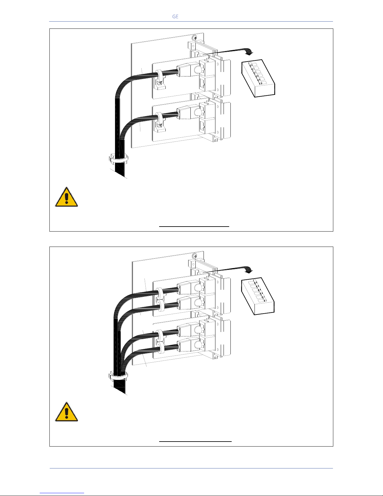
Critical Power
Modifications reserved
Page 65/146
GE_UPS_OPM_TLE_SCE_M60_M80_1GB_V020.docx
User Manual TLE Series 600 & 800 CE S1
Fig. 5.10.2-2 Bus connection on first and last units
Final units, first and last, of a RPA Parallel System
On the two boards P13/P14 – IM0222 – Bus Interface Board, of the first and last units of a Parallel
System, the switches SW1-1/2/3/4/5/6 MUST BE IN POSITION ON (see Fig. 5.10.2-2).
Fig. 5.10.2-3 Bus connection on intermediate units
Intermediate units of a RPA Parallel System
On the two boards P13/P14 – IM0222 – Bus Interface Board, of the intermediate units of a Parallel
System, the switches SW1-1/2/3/4/5/6 MUST BE IN POSITION OFF (see Fig. 5.10.2-3).
J2
J1
J2
J1
B
A
J1A/1
J1B/1
1
2
3
SW1
4
5
6
ON
TLES_160-400_S1_RPA-IM0222_02
J2
J1
J2
J1
B
A
J1A/1
J1B/2÷5
J1B/1
J1A/2÷5
1
2
3
4
5
6
ON
SW1
TLES_160-400_S1_RPA-IM0222_03
Page 66
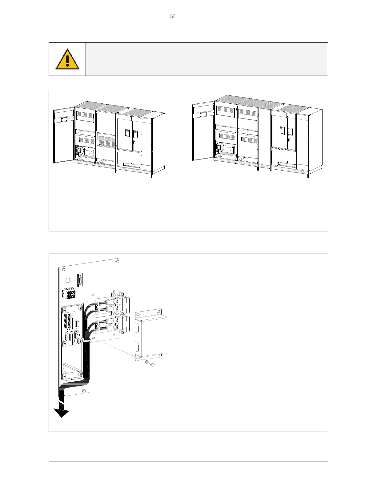
Critical Power
Modifications reserved
Page 66/146
GE_UPS_OPM_TLE_SCE_M60_M80_1GB_V020.docx
User Manual TLE Series 600 & 800 CE S1
5.10.3 Control bus cable location
WARNING !
This installation must be verified by trained personnel before the initial start-up.
ENSURE THAT THE UPS INSTALLATION IS COMPLETELY POWERED DOWN.
Fig. 5.10.3-1 TLE Series 600
View electronic module on intermediate unit
Fig. 5.10.3-2 TLE Series 800
View electronic module on intermediate unit
Access to the control bus connection
The communication bus cable connectors are placed on the two boards “P13/P14 – IM0222 – Bus
Interface Board” (see Fig. 5.10.3-1 and 5.10.3-2).
Fig. 5.10.3-3 View electronic module on intermediate unit
Control bus cables connection
Plug the cables J1A – J2A (1/2/3/4/5) and J1B –
J2B (1/2/3/4/5) on the connectors J1A – J2A
and J1B – J2B placed on the two boards
“P13/P14 – IM0222 – Bus Interface Board”.
Fix the communication bus cables J1A – J2A
(1/2/3/4/5) and J1B – J2B (1/2/3/4/5) with the
provided cable clamps “A”.
TLES_600_S1_RPA connection_01
EPO
EPO
-
+
12
Q1
0 OFF
I ON
TLES_800_S1_RPA connection_01
EPO
EPO
-
+
12
Q1
0 OFF
I ON
J2
J1
J2
J1
B
A
J1A/1
J1B/2÷5
J1B/1
J1A/2÷5
-
+
EPO
EPO
TLES_160-400_S1_RPA connection_02
Page 67
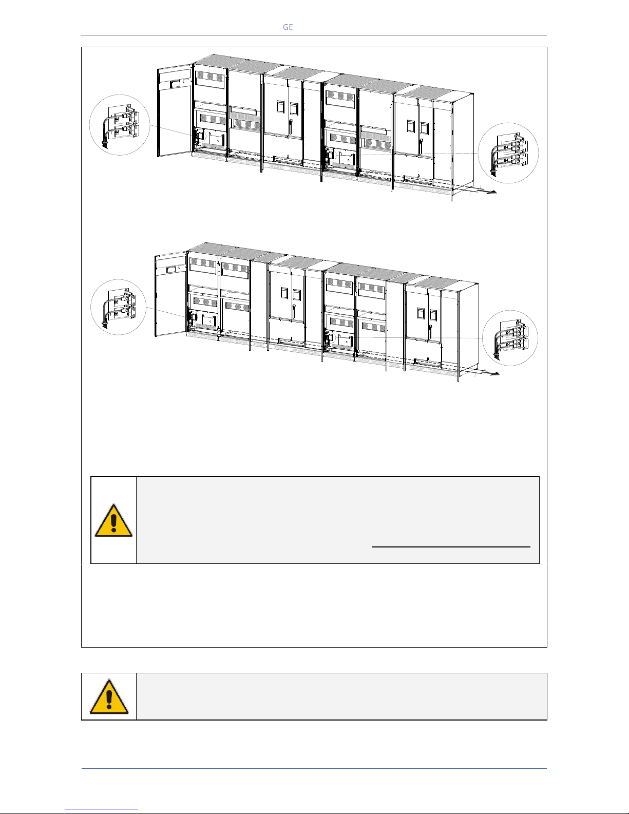
Critical Power
Modifications reserved
Page 67/146
GE_UPS_OPM_TLE_SCE_M60_M80_1GB_V020.docx
User Manual TLE Series 600 & 800 CE S1
Fig. 5.10.3-4 TLE Series 600 - Control Bus cable routing and connection
Fig. 5.10.3-5 TLE Series 800 - Control Bus cable routing and connection
Control bus cables routing
Place and fix the cables J1A – J2A (1/2/3/4/5) and J1B – J2B (1/2/3/4/5) inside the UPS cabinets in
the position illustrated in the drawing Fig. 5.10.3-4 and 5.10.3-5.
NOTE !
Pay attention when cabling and routing the communication bus cables J1A – J2A
(1/2/3/4/5) and J1B – J2B (1/2/3/4/5) inside the UPS cabinet.
In case one unit must be removed from the Parallel System, the communication
bus cables must be taken out the UPS cabinet WITHOUT DISCONNECTING THEM
from the two boards “P13/P14 – IM0222 – Bus Interface Board”.
For reliability reasons the cables J1A – J2A (1/2/3/4/5) and J1B – J2B (1/2/3/4/5) connecting the units
should be run in separated protected conduits (as indicated in Fig. 5.10.3-4 and 5.10.3-5) separated
from the power cables.
It is important that the cable J1A – J2A (1/2/3/4/5) must be the same length as cable J1B – J2B
(1/2/3/4/5).
WARNING !
Connection and commissioning of an additional UPS to an existing Parallel System
must be performed by a service engineer from of your Service Centre.
TLES_600_S1_RPA connection_03GB
-
+
12
Q1
0 OFF
I ON
J2
J1
J2
J1
B
A
J1A/1
J1B/1
UPS 1
-
+
12
Q1
0 OFF
I ON
UPS 2
UPS 1
J2
J1
J2
J1
B
A
J1A/1
J1B/2÷5
J1B/1
J1A/2÷5
UPS 2/3/4/5
UPS 3, 4, 5, 6
J1B/2÷5
J1A/2÷5
TLES_800_S1_RPA connection_03GB
J2
J1
J2
J1
B
A
J1A/1
J1B/1
UPS 1
UPS 1
J2
J1
J2
J1
B
A
J1A/1
J1B/2÷5
J1B/1
J1A/2÷5
UPS 2/3/4/5
UPS 3, 4, 5, 6
J1B/2÷5
J1A/2÷5
-
+
12
Q1
0 OFF
I ON
-
+
12
Q1
0 OFF
I ON
UPS 2
Page 68
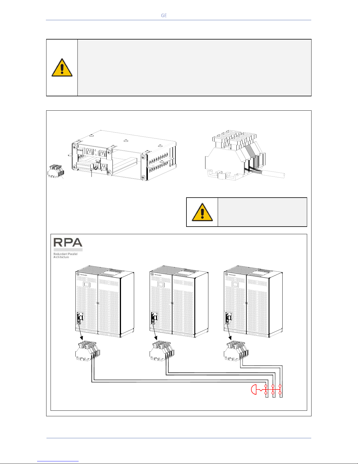
Critical Power
Modifications reserved
Page 68/146
GE_UPS_OPM_TLE_SCE_M60_M80_1GB_V020.docx
User Manual TLE Series 600 & 800 CE S1
5.11 EPO COMMAND CONNECTION (EMERGENCY POWER OFF)
WARNING !
The connection of an emergency button EPO (Emergency Power Off) must be
performed by QUALI FIED S ERVICE PE R SONNEL only when the UPS is
COMPLETELY POWERED DOWN.
BE AWARE !
The reliability of the system depends on this contact NC (Normally Closed)!
An Emergency button (Normally Closed voltage-free contact) can be connected on terminals XA /
EPO-1, EPO-2. Max. rating XA terminals: 2.5mm2.
Fig. 5.11-1 XA terminal block for EPO command connection
When opened, this contact causes the immediate
opening of the Contactors K6 and K7 as well as
the shut-down of Rectifier, Inverter and Static-
Switch.
NOTE !
This procedure could imply a
Load shut-down.
In a Parallel System a separate NC (Normally Closed) contact must be connected
individually to each unit.
Fig. 5.11-2 XA “EPO - Emergency Power Off” – RPA Parallel System connection schematics
TLES_160-400_S1_Customer interface-XA_01
Customer Interface
XA
EPO
EPO
+
-
1
12
13
14
15
16
17
18
19
20
21
22
2
3
4
5
6
7
8
9
10
11
SGSE_400-500_S3_Terminals XA_01
XA
EPO
EPO
+
-
TLES_600_S1_UPS_EPO-RPA connection schematic_GE_01
EP O
EP O
+
-
EP O
EP O
+
-
EP O
EP O
+
-
XA XA XA
EPO
12
-
+
12
-
+
12
-
+
Page 69
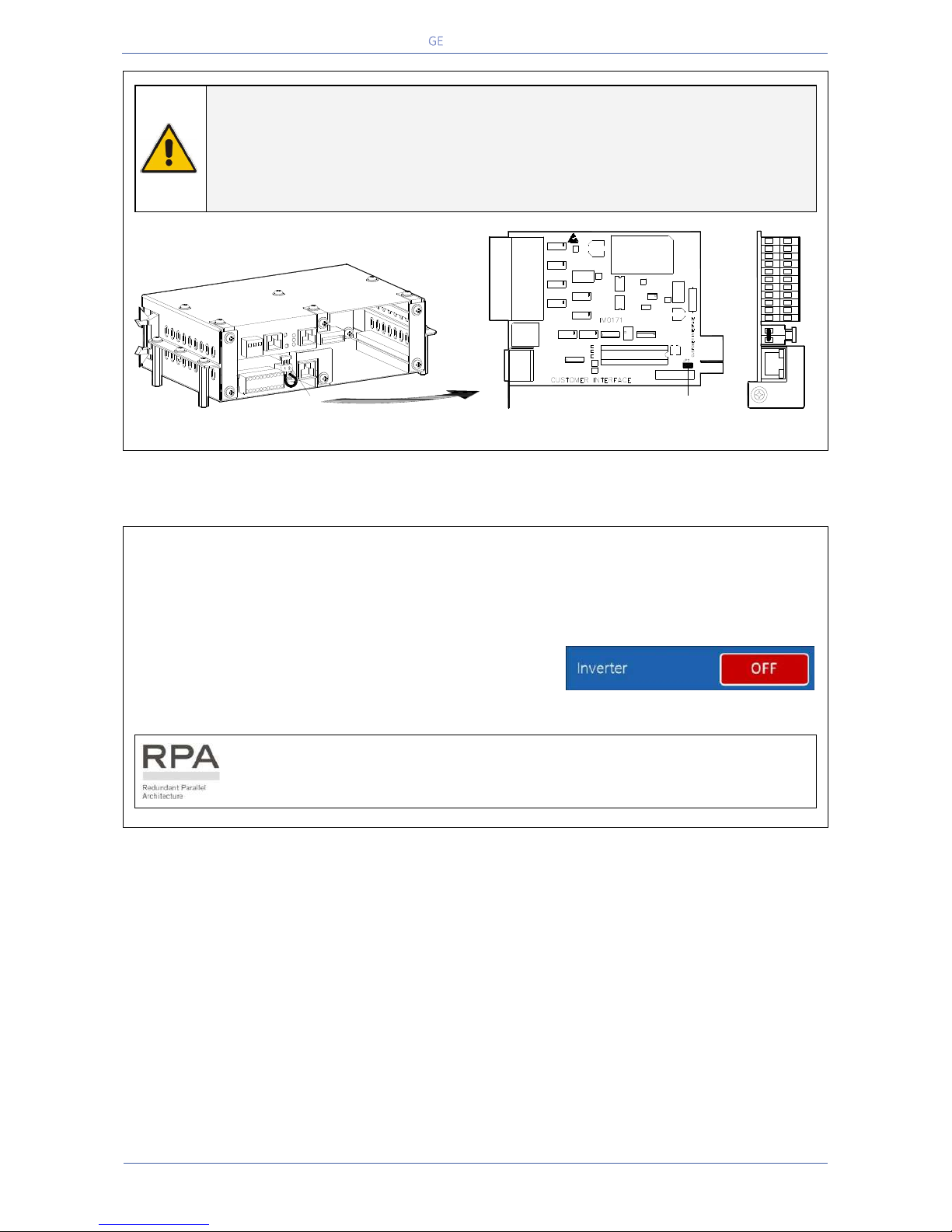
Critical Power
Modifications reserved
Page 69/146
GE_UPS_OPM_TLE_SCE_M60_M80_1GB_V020.docx
User Manual TLE Series 600 & 800 CE S1
NOTE !
To operationalize this function, in case that the UPS was provided with one or
more cards “P4 - Customer Interface”, there must be on each card the following:
- Remove the cable short-circuiting terminals X2 / 1, 2 (see Fig. 5.11-3).
- Remove the Jumper JP2 (see Fig. 5.11-3).
Fig. 5.11-3 X2 terminal block and Jumper JP2 on the P4 – Customer Interface Board
When the “EPO - Emergency Power Off” has been activated, the system must be restored as
follows:
Realise the push-button “EPO - Emergency Power Off” (contact on XA / EPO-1, EPO-2 is closed
again).
Perform the “Inverter OFF” command from the screen:
Commands 1 / Inverter / OFF.
(see User Manual to Section 7.5).
In case of a Parallel System perform the “Inverter OFF” command from the
screen “Commands 1 / Inverter / OFF” of each unit connected on the Parallel Bus
and having its output switch “Q1 - UPS Output” closed.
CNT_Connectivity rack_X2-EPO_01
16
15
4
19
18
17
20
9
8
7
6
5
14
13
12
3
2
1
22
11
21
10
X2
SNMP card
Customer interface
X1
X2
J1
JP2
1 2
8
19 21 2220
10 119
17 181615
7654
12 1413
321
X1
X2
J1
SE_400-500_S1_Customer interface-JP2_01
Page 70
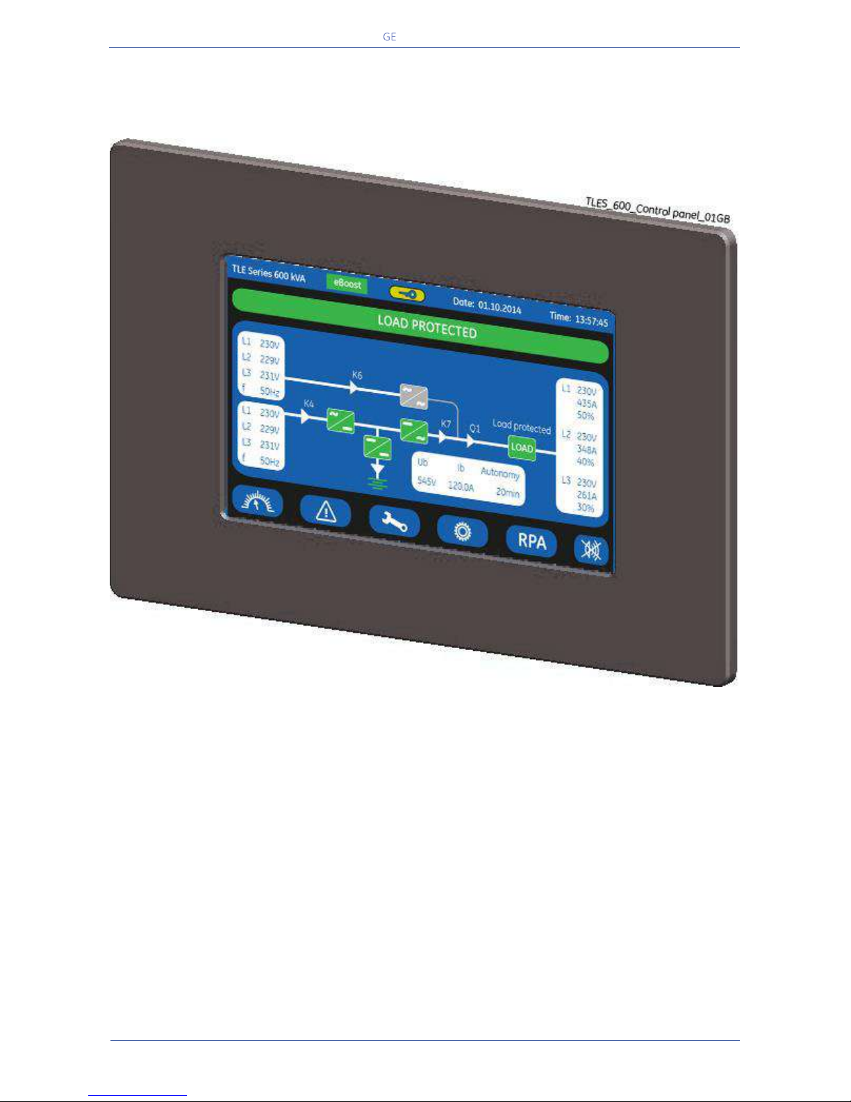
Critical Power
Modifications reserved
Page 70/146
GE_UPS_OPM_TLE_SCE_M60_M80_1GB_V020.docx
User Manual TLE Series 600 & 800 CE S1
6 CONTROL PANEL
6.1 CONTROL PANEL
Fig. 6.1-1 Control Panel
The Control Panel, positioned on the UPS front door, acts as the UPS user interface.
Main features:
LCD Touch screen colour graphic display. See Chapter 7.
Multilanguage communication interface:
English, German, Italian, Spanish, French, Finnish, Polish, Portuguese, Czech, Slovenian, Chinese,
Swedish, Russian and Dutch.
Synoptic diagram indicating UPS status.
Command keys and parameters setting.
UPS status control LED.
Page 71
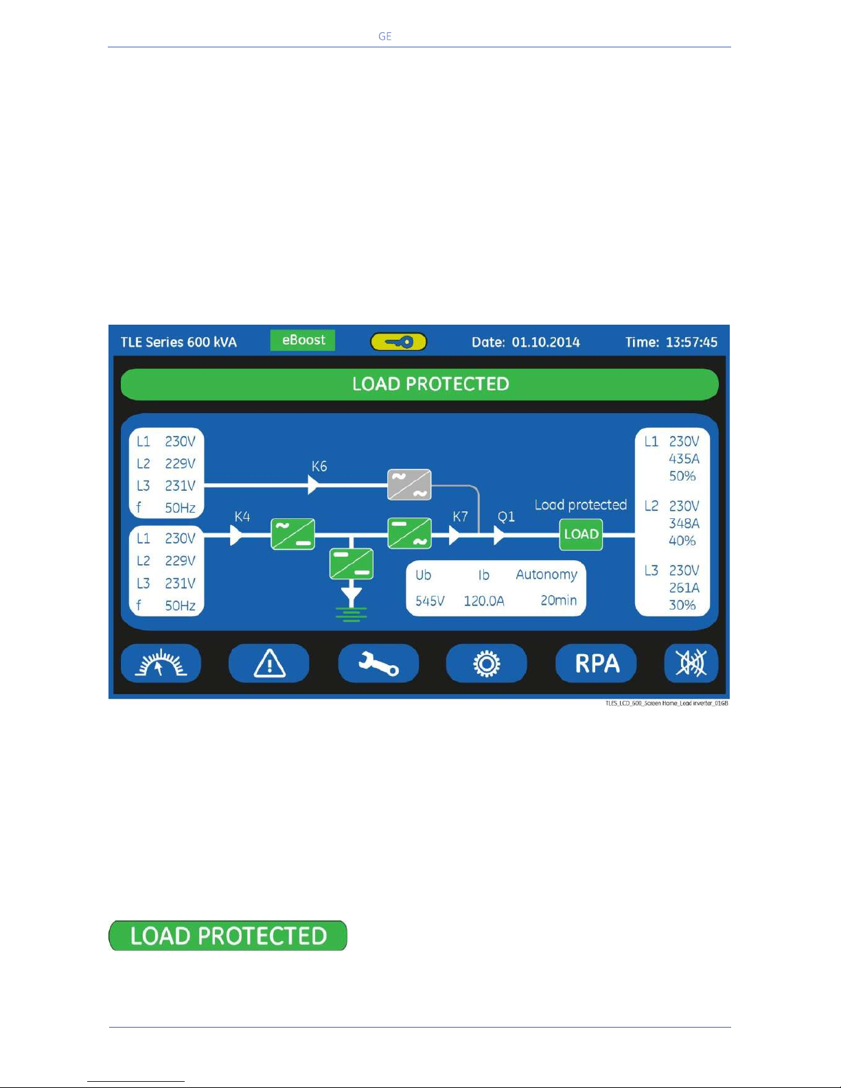
Critical Power
Modifications reserved
Page 71/146
GE_UPS_OPM_TLE_SCE_M60_M80_1GB_V020.docx
User Manual TLE Series 600 & 800 CE S1
7 LCD SCREEN
Composed of an LCD colour “Touch Screen” which provides the following information to users:
Synoptic diagram indicating UPS status.
UPS operating, AC and DC metering information.
History of events (alarms and messages).
Functionality can be programmed to meet customer needs by changing parameters.
Operation commands of the UPS.
7.1 HOME SCREEN
Fig. 7.1-1 LCD screen
The LCD screen, after 5 minutes of inactivity, shuts down the backlight.
To reactivate it, it is sufficient to press any keys mentioned to Section 7.1.1.
If the keypad remains inactive for 5 minutes or longer, during the viewing of a screen such as
MEASURES, EVENTS, SETUP, RPA Parallel System or COMMANDS, the LCD screen returns automatically to
the main screen.
Pressing the key “UPS status” for a few seconds
automatically sets the “ENGLISH” language on the LCD
screen.
Page 72
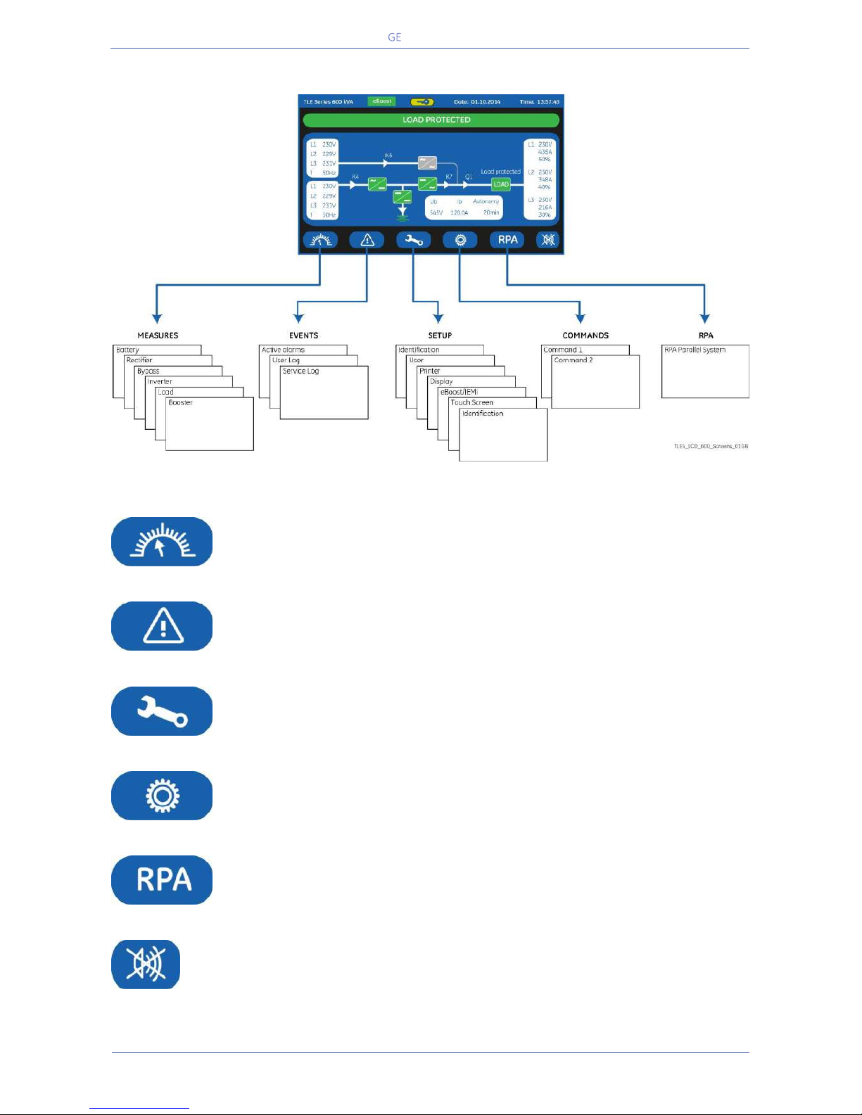
Critical Power
Modifications reserved
Page 72/146
GE_UPS_OPM_TLE_SCE_M60_M80_1GB_V020.docx
User Manual TLE Series 600 & 800 CE S1
7.1.1 Description of the selection keys
Fig. 7.1.1-1 LCD screen
MEASURES
Shows electric parameters values and statistics of use.
See Section 7.2.
EVENTS
Shows in chronological order, all the events occurred (alarms,
messages, commands, handling, etc.).
See Section 7.3.
SETUP
Allows the user to customize some UPS functions to specific
requirements and to view UPS identification data.
See Section 7.4.
COMMANDS
Allows the user to execute UPS operation commands.
See Section 7.5.
RPA
Parallel
System
Shows the status of operation of the RPA Parallel System.
See Section 7.6.
MUTE
Key to reset general alarm and buzzer.
Page 73
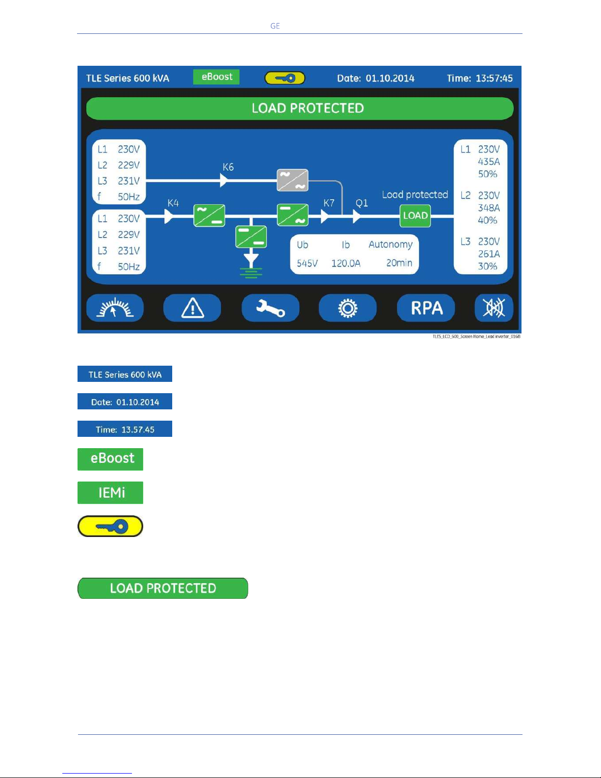
Critical Power
Modifications reserved
Page 73/146
GE_UPS_OPM_TLE_SCE_M60_M80_1GB_V020.docx
User Manual TLE Series 600 & 800 CE S1
7.1.2 Description of the signalling LEDs
Fig. 7.1.2-1 LCD screen
UPS model
Date (format “DD.MM.YYYY”).
Time (format “HH.MM.SS”).
eBoost (green colour)
LED ON/lit indicates that the UPS is operating in eBoost™ mode.
IEMi (green color)
LED ON/lit indicates that the UPS is operating in IEMi mode.
Service Key (yellow colour)
Key for disabling the Service Key procedure.
Used only by the Service Centre
LEDS UPS STATUS
LED LOAD PROTECTED (green colour)
When lit, indicates that the UPS is functioning correctly and the Load is system protected (Load
supplied either from inverter or from Automatic Bypass in case of eBoost™ Operation Mode).
When blinking, indicates that a regular maintenance service is needed (SERVICE REQUIRED).
May be reset by a SERVICE TECHNICIAN only.
See Section 11 – Maintenance – Service check.
The LED is OFF when the “Q1 - UPS Output switch” is open, indicating that the Inverter is in service
mode, not supplying the Load.
Page 74
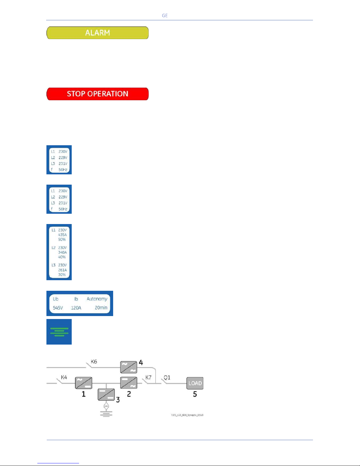
Critical Power
Modifications reserved
Page 74/146
GE_UPS_OPM_TLE_SCE_M60_M80_1GB_V020.docx
User Manual TLE Series 600 & 800 CE S1
LED ALARM (yellow colour)
It blinks when one or more alarm is activated. The internal Buzzer is ON.
The LED remains blinking (with the alarm condition still present) and the buzzer stops when the key
“MUTE” is pressed.
The LED ALARM is also lighted when the Load is not protected by UPS or in case Q1 is open.
LED STOP OPERATION (red colour)
It warns about the imminent inverter stop (default parameter = 3 min.) and the consequent Load shutdown as result of:
The battery is fully discharged and the Load cannot be transferred on Mains.
Overtemperature or overload condition (>102%) and the Load cannot be transferred on Mains.
Bypass
Data regarding Bypass.
See Section 7.2.
Rectifier
Data regarding Rectifier.
See Section 7.2.
Load output
Data regarding Load.
See Section 6.2.
Battery
Data regarding Battery.
See Section 6.2.
Green color: indicates battery charged.
Yellow color: indicates STOP OPERATION status.
Red color: indicates low battery.
LEDs on Synoptic Diagram
LED 1 Rectifier
LED 2 Inverter
LED 3 Booster/Battery charger
LED 4 Automatic Bypass
LED 5 LOAD
Page 75
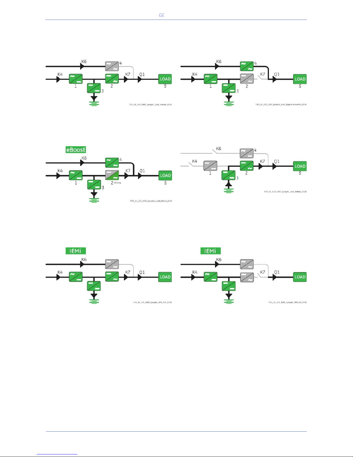
Critical Power
Modifications reserved
Page 75/146
GE_UPS_OPM_TLE_SCE_M60_M80_1GB_V020.docx
User Manual TLE Series 600 & 800 CE S1
Examples of typical scenarios in the Synoptic Diagram:
Load supplied by Inverter
Load supplied by Automatic Bypass
eBoost Operation Mode
Load supplied by Battery
IEMi Operation Mode, unit on-line
IEMi Operation Mode, unit stand-by
Page 76
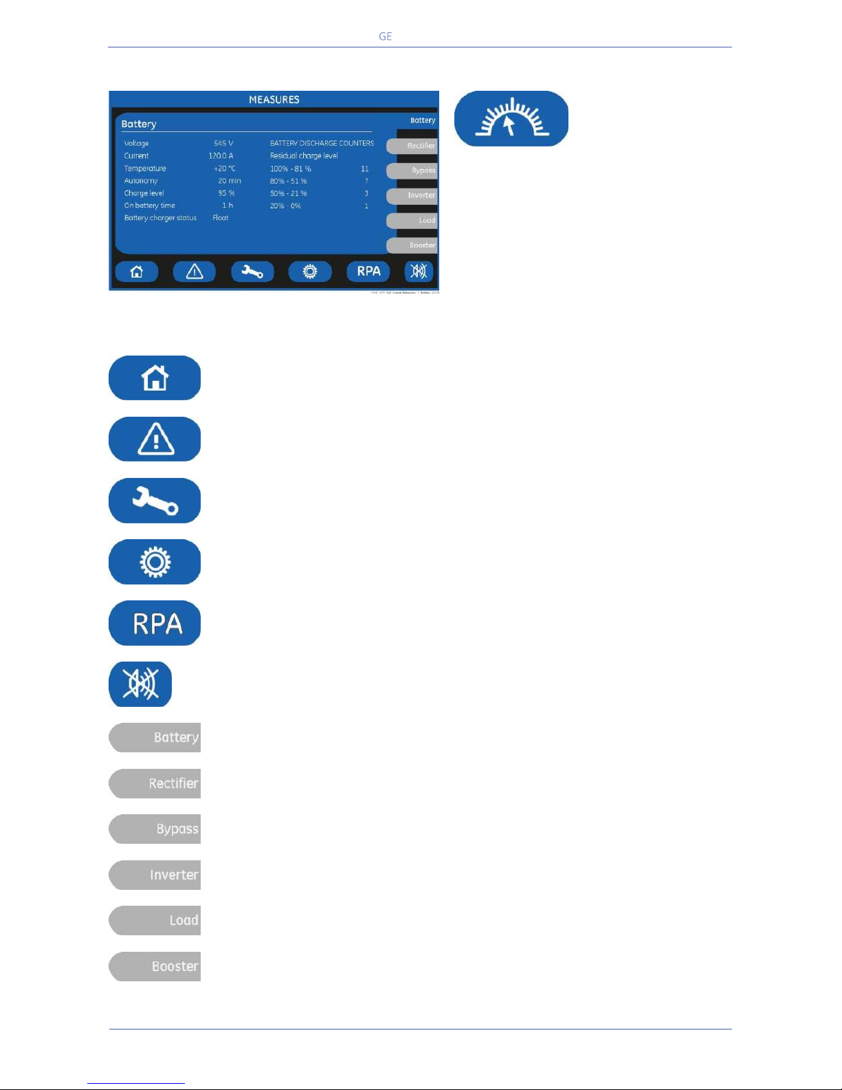
Critical Power
Modifications reserved
Page 76/146
GE_UPS_OPM_TLE_SCE_M60_M80_1GB_V020.docx
User Manual TLE Series 600 & 800 CE S1
7.2 MEASURES
MEASURES
The MEASURES mode is entered any time the
“MEASURES” key is pressed.
The LCD screen will indicate a series of
screenshots showing the measures of all
electric parameters like AC, DC and various
statistics.
In this mode the keys perform the following functions:
Return to HOME screen.
Shows the main screen EVENTS.
See Section 7.3.
Shows the main screen SETUP.
See Section 7.4.
Shows the main screen COMMANDS.
See Section 7.5.
Shows the operating status of the RPA PARALLEL SYSTEM.
See Section 7.6.
Key to reset general alarm and buzzer.
Shows the screen Battery.
Shows the screen Rectifier.
Shows the screen Bypass.
Shows the screen Inverter.
Shows the screen Load.
Shows the screen Booster.
Page 77
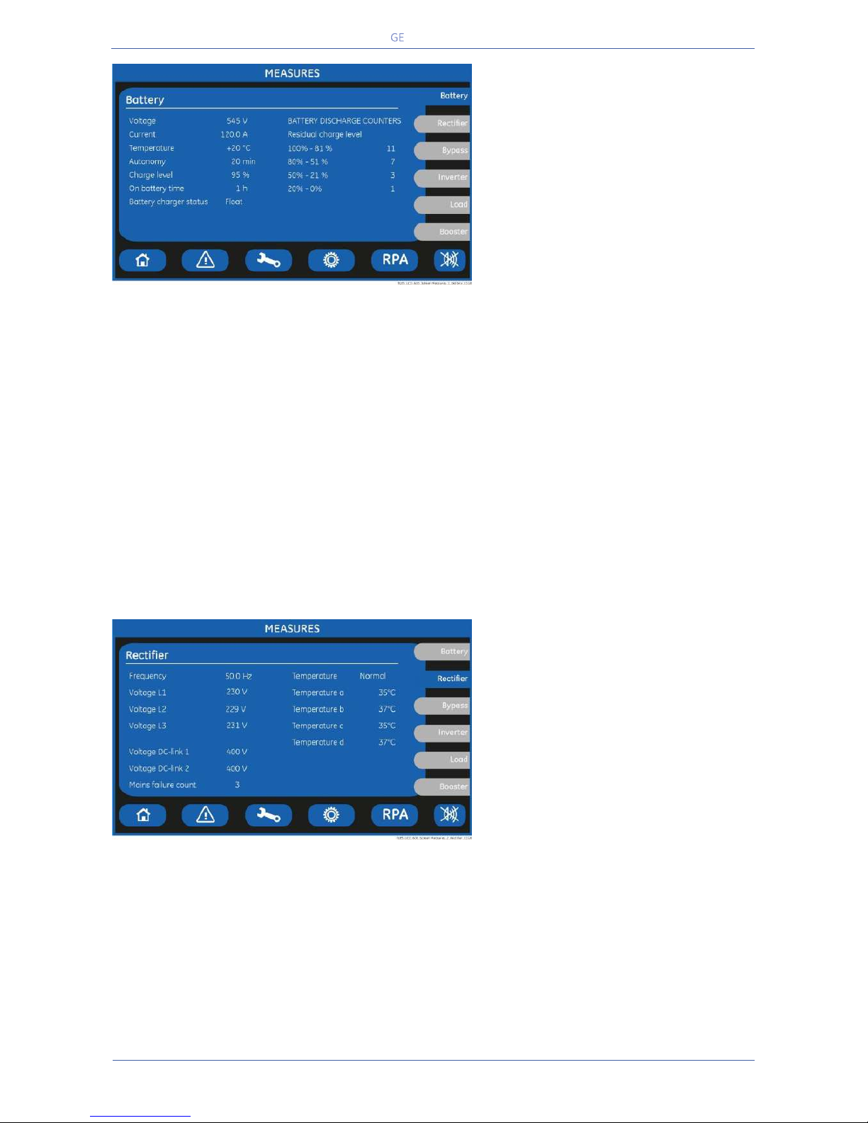
Critical Power
Modifications reserved
Page 77/146
GE_UPS_OPM_TLE_SCE_M60_M80_1GB_V020.docx
User Manual TLE Series 600 & 800 CE S1
BATTERY SCREEN
Voltage
The battery voltage.
Current
The battery current (negative values
correspond to the discharge of the
battery).
Temperature
The temperature of the battery (“XXX”
indicates sensor disabled).
Autonomy
The estimated backup time with the present Load.
Note: the backup time is computed given the unit load.
Therefore, during IEMi Operation Mode, on-line units may show a reduced backup time.
However, following a power outage, all inverters are forced on-line.
Therefore, during battery operation every unit shows the true battery autonomy.
Charge level
The battery charge level.
On battery time
Total operating time of the UPS on battery (in hours).
BATTERY DISCHARGE COUNTER / Residual Charge Level
The number of discharges combined with the percentage of the available residual battery capacity at
the time utility power is restored.
Battery charger status
Battery charge status (Off / Float / Boost).
RECTIFIER SCREEN
Frequency
The input frequency of the Rectifier.
Voltage L1 / Voltage L2 / Voltage L3
3-phase Mains voltage PHASE /NEUTRAL.
Voltage DC-link 1
DC-Link 1 voltage.
Voltage DC-link 2
DC-Link 2 voltage.
Main failure count
Total number of times a gap of mains in the Rectifier has been reordered.
Temperature
Rectifier inlet L1 Coil temperature (Normal / Alarm).
Temperature a / b / c / d
a- Temperature of the Rectifier bridge (lower left module).
b- Temperature of the Rectifier bridge (upper left module).
c- Temperature of the Rectifier bridge (lower right module).
d- Temperature of the Rectifier bridge (upper right module – only for 800 kVA).
Page 78
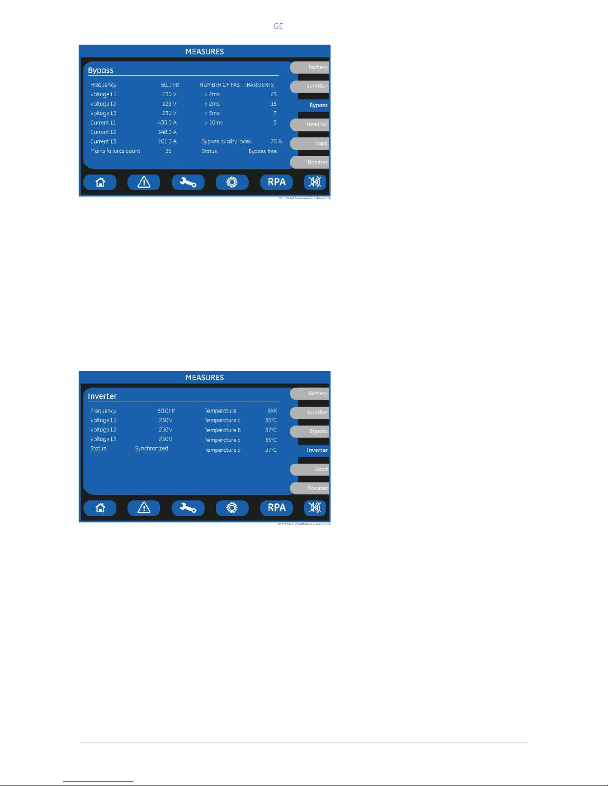
Critical Power
Modifications reserved
Page 78/146
GE_UPS_OPM_TLE_SCE_M60_M80_1GB_V020.docx
User Manual TLE Series 600 & 800 CE S1
BYPASS SCREEN
Frequency
The frequency of the Mains Input.
Voltage L1 / Voltage L2 / Voltage L3
3-phase Mains voltage PHASE
/NEUTRAL.
Current L1 / Current L2 / Current L3
Mains Input current for the 3-phases.
Main failure count
The total number of minor Mains faults (Bypass Mains out of tolerance faults).
NUMBER OF FAST TRANSIENTS
The number of fast transients occurred on the bypass utility on the last seven days.
Bypass quality index
The statistic evaluation in % (100= good; 0= bad) of the Bypass mains.
Status
Bypass status: Bypass free / Bypass blocked.
INVERTER SCREEN
Frequency
The output frequency of the Inverter.
Voltage L1 / Voltage L2 / Voltage L3
3-phase output voltage
PHASE/NEUTRAL.
Status
The synchronization status of the
Inverter with respect to Mains:
- Synchronized.
- Not synchronized.
Temperature
“XXX” indicates disabled function.
Temperature a
The temperature of the Inverter bridge (lower left module).
Temperature b
The temperature of the Inverter bridge (upper left module).
Temperature c
The temperature of the Inverter bridge (lower right module).
Temperature d
The temperature of the Inverter bridge (upper right module – only for 800 kVA).
Page 79
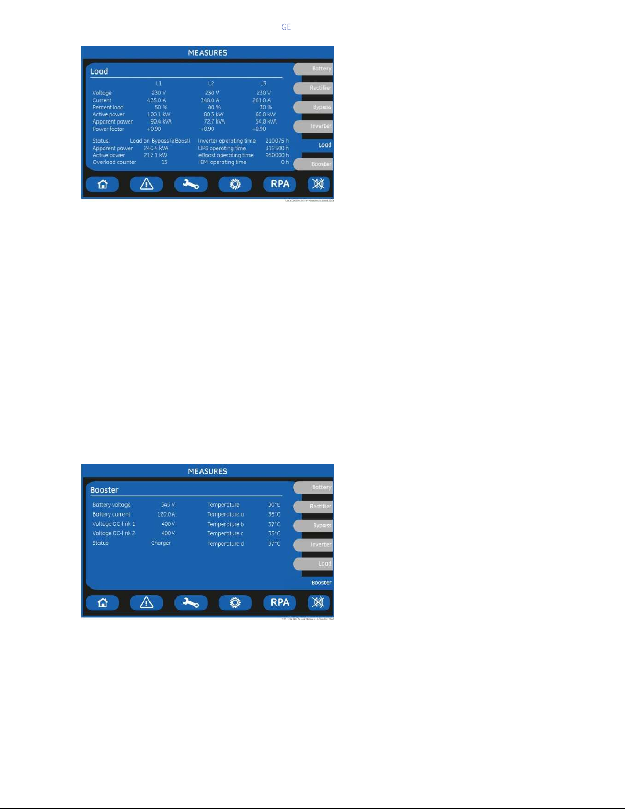
Critical Power
Modifications reserved
Page 79/146
GE_UPS_OPM_TLE_SCE_M60_M80_1GB_V020.docx
User Manual TLE Series 600 & 800 CE S1
LOAD SCREEN
Voltage L1 / L2 / L3
Output voltage PHASE/NEUTRAL for each
phase.
Current L1 / L2 / L3
The output current as RMS values for
each phase.
Percent load L1 / L2 / L3
The output Load as percentage for each
phase.
Active power
Load active power (kW) for each phase.
Apparent power
Load apparent power (kVA) for each phase.
Power factor
Load power factor: + inductive load / - capacitive load
Status
Source of the power supplied to the Load.
Apparent power
Total apparent Load power (kVA).
Active Power
Total effective Load power (kW).
Overload counter
Total number of detected output overloads.
Inverter operating time
Total operating time for the Inverter (in hours).
UPS operation time
Total operating time for the UPS (in hours).
eBoost operation time
Total operating time for the UPS in eBoost™ Operation Mode (in hours).
This counter is displayed only when eBoost™ Operation Mode is available
(option).
IEMi operation time
Total operating time for the UPS in IEMi Operation Mode (in hours).
This counter is displayed only when IEMi Operation Mode is available (option).
BOOSTER SCREEN
Battery voltage
The battery voltage.
Battery current
The battery current (negative values
correspond to the discharge of the
battery).
Voltage DC-link 1
DC-link 1 voltage.
Voltage DC-link 2
DC-link 2 voltage.
Status
Booster status (Off / Booster / Charger).
Temperature
Temperature of the 4th leg’s bridge.
Temperature a / b / c / d
a- Booster temperature (lower left module).
b- Booster temperature (upper left module).
c- Booster temperature (lower right module).
d- Booster temperature (upper right module – only for 800 kVA).
Page 80
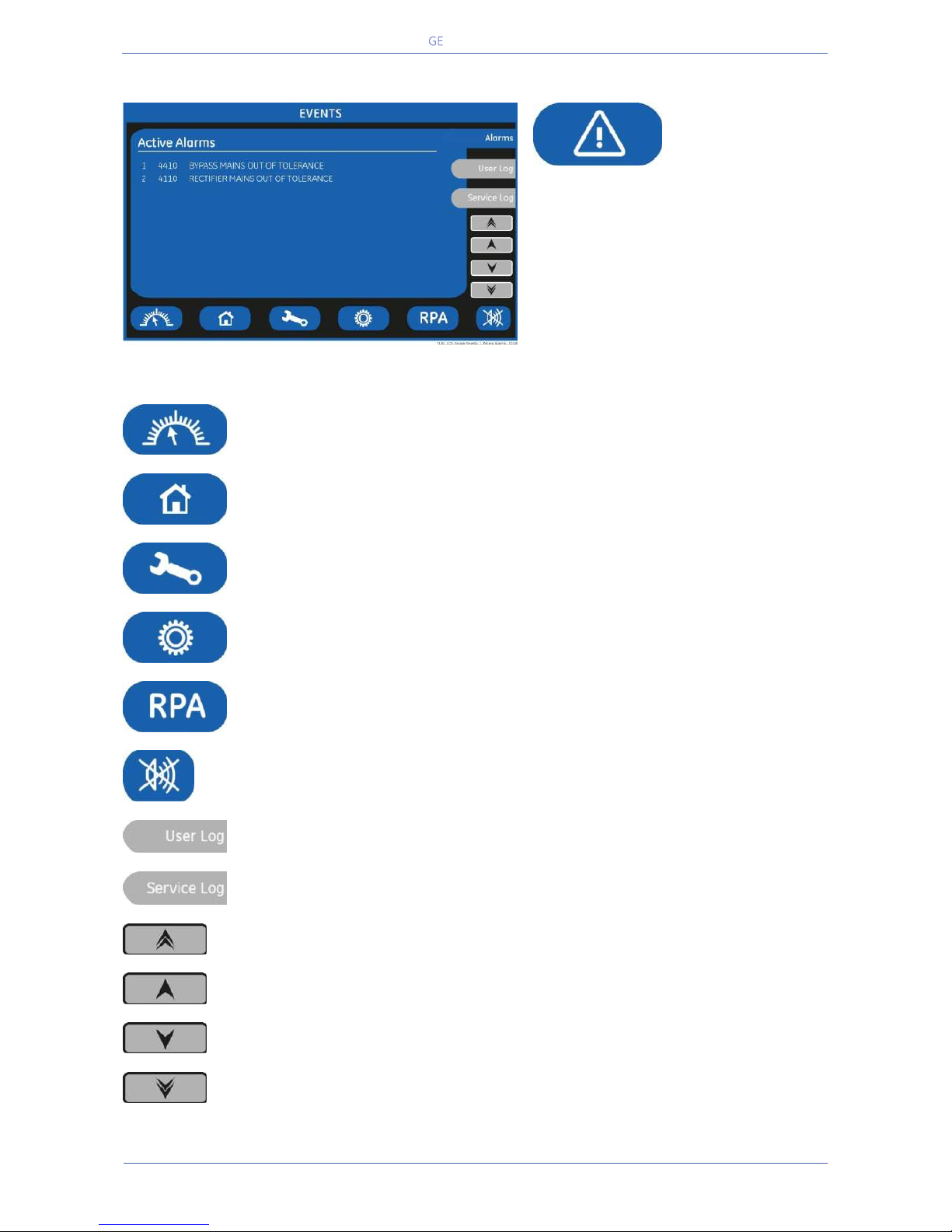
Critical Power
Modifications reserved
Page 80/146
GE_UPS_OPM_TLE_SCE_M60_M80_1GB_V020.docx
User Manual TLE Series 600 & 800 CE S1
7.3 EVENTS
EVENTS
The EVENTS mode is entered any time the
“EVENTS” key is pressed.
The LCD will display a series of screens
corresponding to the last 511 events (User
Log).
In this mode the keys perform the following functions:
Shows the main screen MEASURES.
See Section 7.2.
Return to HOME screen.
Shows the main screen SETUP.
See Section 7.4.
Shows the main screen COMMANDS.
See Section 7.5.
Shows the operating status of the RPA PARALLEL SYSTEM.
See Section 7.6.
Key to reset general alarm and buzzer.
Shows the screen User Events.
Shows the screen Service Events. Reserved for the Service Centre.
Shows the previous 50 events.
Shows the previous 5 events.
Shows the next 5 events.
Shows the next 50 events.
Page 81
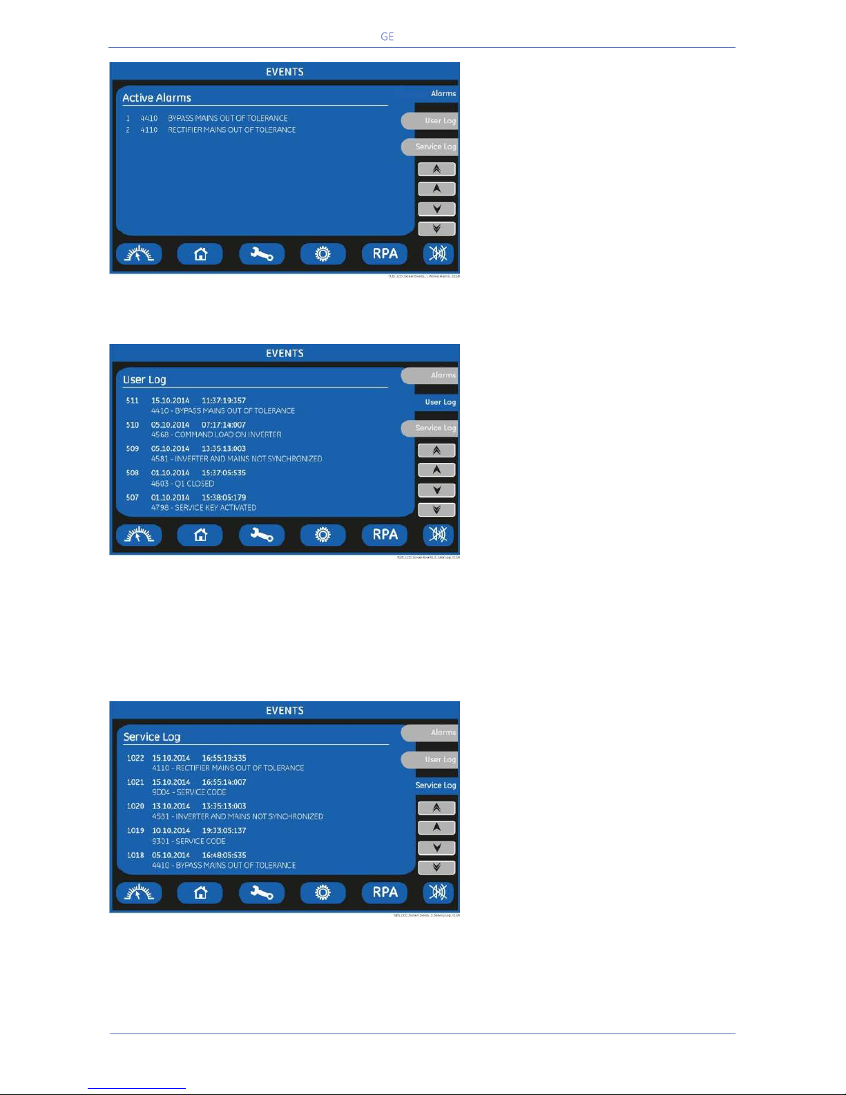
Critical Power
Modifications reserved
Page 81/146
GE_UPS_OPM_TLE_SCE_M60_M80_1GB_V020.docx
User Manual TLE Series 600 & 800 CE S1
SCREEN ACTIVE ALARMS
Active Alarms
Shows active events with their GE
standard code and a text describing the
event in the selected language.
SCREEN USER LOG
User Log
Chronologically view 5 events per
screenshot.
Event characteristic:
- Number chronologically assigned to
an event (Nr. 511 is the more recent,
Nr. 1 is the first).
- Data (DD/MM/YYYY).
- Exact hour of the moment when the
event occurred (HH/MM/SS/
thousandth).
- Number of standard GE code of the
event.
- Explicit text describing the event in
the selected language.
SCREEN SERVICE LOG
Service Log
Chronologically view 5 events per
screenshot with service related info.
Event characteristic:
- Number chronologically assigned to
an event (Nr. 1022 is the more
recent, Nr. 1 is the first).
- Data (DD/MM/YYYY).
- Exact hour of the moment when the
event occurred (HH/MM/SS/
thousandth).
- Number of standard GE code of the
event.
Page 82

Critical Power
Modifications reserved
Page 82/146
GE_UPS_OPM_TLE_SCE_M60_M80_1GB_V020.docx
User Manual TLE Series 600 & 800 CE S1
7.3.1 Events (alarms and messages)
Each of the following listed events, alarm or message, can be displayed on the LCD screen, on a PC with
the software “GE Data Protection” installed or with the monitoring system “GE iUPSGuard”.
Alarms and Messages are differently specified because the alarms are indicating an abnormal
functioning of the UPS (which are additionally signalled with the LED ALARM and acoustically with the
buzzer), while the messages indicate the various states of operation of the UPS (stored in the events list,
but not activating the LED ALARM and the acoustical alarm).
7.3.2 Alarms list
Code
Alarm
Description
4000
SETUP VALUES LOST
Parameters are lost and have been replaced with
default values.
Please call nearest Service Centre for intervention.
4001
REGULATION BOARD FAILURE
A blocked DSP on the Control board causes this
alarm, and consequently the shut-down of Rectifier
and inverter and the opening of K3.
4004
UPS FAILURE ON PARALLEL SYSTEM
The master unit detected the slave unit missing on
the communication bus even though switch Q1 is
still closed.
4006
BUS JA CRC FAILURE
The parallel communication bus system is subject
to high errors rate on channel JA.
4007
BUS JB CRC FAILURE
The parallel communication bus system is subject
to high errors rate on channel JB.
4008
BUS JA FAILURE
There is an interruption in the channel JA of the
parallel communication bus system.
4009
BUS JB FAILURE
There is an interruption in the channel JB of the
parallel communication bus system.
4010
CONNECTIVITY BUS FAILURE
The connectivity communication bus is faulty or
interrupted.
4100
RECTIFIER FUSES FAILURE
The u-switch mounted on the Rectifier input fuses
indicates a blown fuse, and consequently it is shut
down.
Clearance of this condition allows you to restart
the Rectifier.
4102
K4 CLOSING FAILURE
K4 not closed despite a closing command being
issued.
Signalled by auxiliary contact. Rectifier cannot
start.
4103
K4 OPENING FAILURE
K4 not open despite an opening command being
issued.
Signalled by auxiliary contact.
Mains remains connected to Rectifier bridge.
4104
BATTERY FUSES FAILURE
This function, when enabled on input
programmable relays (password required), warns
the user about the external Battery Fuses failure or
MCB opening, signalled by NO free contact.
4105
RECTIFIER OVERTEMPERATURE
Temperature sensor indicates a situation of
overtemperature on the Rectifier bridge.
Only the alarm is given.
The Rectifier, when in an Off state, cannot start as
long as this condition persists.
Page 83
Critical Power
Modifications reserved
Page 83/146
GE_UPS_OPM_TLE_SCE_M60_M80_1GB_V020.docx
User Manual TLE Series 600 & 800 CE S1
Code
Alarm
Description
4106
RECTIFIER TRANSFORMER
OVERTEMPERATURE
The temperature sensor inside the input
transformer winding indicates
overtemperature.
Only the alarm is given.
The Rectifier, when in an Off state, cannot start
as long as this condition persists.
4110
RECTIFIER MAINS OUT OF TOLERANCE
Rectifier Mains Input is out of tolerance
(voltage, frequency or phase sequence).
4115
LOW BATTERY VOLTAGE
The Battery has been discharged and reached
“stop operation” time-out (default 3 minutes),
and the Inverter will be shut down.
It will restart automatically only when the
Battery has recharged enough for a minimum
runtime.
4116
HIGH BATTERY VOLTAGE
Dangerous high DC Voltage caused inverter
shut-down.
Inverter restarts automatically after Battery
returns to floating voltage.
4117
BATTERY EARTH FAULT
A leakage current to earth has been detected
on the DC circuit.
4118
BATTERY FAULT
During battery test the voltage falls under the
critical level (depending setting parameters).
Battery test is stopped.
4121
HIGH DC RIPPLE
A high ripple is present in the battery voltage.
4125
HIGH DC-LINK VOLTAGE
Detection of high voltage on the DC-link.
The rectifier, booster and inverter will switch off
for protection purposes.
The rectifier may only be switched on again if
the DC-Link’s voltage value falls below 430V.
4126
4th LEG CONTROL SATURATION (Imax)
The current in the fourth leg has reached its
highest value.
4130
TURN ON RECT. OR SHUTDOWN UPS
Rectifier and Inverter are OFF.
The DC power supply is discharging the
Battery.
Rectifier must be restarted or Battery must be
disconnected in order to avoid damage.
4140
RECTIFIER CONTROL FAILURE
Rectifier Voltage hasn’t reached the set value
(probably fault on regulation loop).
LED Rectifier on control panel is blinking.
4141
ISMAX DETECTION RECTIFIER
After 3 IS-Max condition within the time frame
specified in respective parameter, the Rectifier
remains shut-down.
4142
RECTIFIER CURRENT MAX
Will cause immediate shut-down of the
Rectifier.
Based on the value inserted in the respective
parameter.
4143
BOOSTER/BATTERY CHARGER CURRENT
MAX
Detection of maximum current in the
booster/battery charger.
The Booster/Battery charger and Inverter will
switch off for protection purposes.
Page 84

Critical Power
Modifications reserved
Page 84/146
GE_UPS_OPM_TLE_SCE_M60_M80_1GB_V020.docx
User Manual TLE Series 600 & 800 CE S1
Code
Alarm
Description
4146
4TH LEG DRIVER FAILURE
The Booster’s driver indicates the presence of a
defect which switches the power off.
4147
BATTERY CHARGER DRIVER FAILURE
The Battery charger driver indicates a defect,
switching it off.
4150
BOOSTER OVERTEMPERATURE
The temperature of the booster bridge exceeds
the machine’s set limit or the coil’s sensor is on.
4151
4TH LEG OVERTEMPERATURE
The temperature of the 4
th
leg’s bridge exceeds
the machine’s set limit.
4301
INVERTER FUSES
The alarm signals an inverter outlet fuses fault,
causing it to switch off immediately.
It may only be manually switched on after the
alarm has ceased.
4304
K7 CLOSING FAILURE
K7 not closed despite a closing command.
Signalled by auxiliary contact.
Load will be supplied by Mains.
4305
K7 OPENING FAILURE
K7 not open despite an opening command.
Signalled by auxiliary contact.
Load will be supplied by Mains.
4307
INVERTER TRANSFORMER
OVERTEMPERATURE
The temperature sensor of the Inverter
Transformer indicates overtemperature.
Elapsed “stop operation” time, Inverter shutdown.
With Mains OK, Load is transferred on Mains.
4308
DC FUSES FAILURE
Blown input DC fuse(s) F1 of the Inverter.
Inverter cannot be started as long as present.
4309
DRIVER FAILURE
An abnormal condition has been detected on one
or more power modules of the Inverter
(temperature or overcurrent).
Inverter shut-down and cannot be started as
long as the alarm is present.
4310
IGBT RECTIFIER DRIVER FAILURE
Indicates a failure on the driver board or the
Rectifier IGBT bridge.
The Rectifier is shut-down.
4311
BOOSTER DRIVER FAILURE
Driver Booster error signal.
4312
INVERTER VOLTAGE OUT
OF TOLERANCE
Inverter Output Voltage is out of the tolerances (
10%).
Inverter is switched OFF.
4320
ISMAX DETECTION
Detection of Inverter Bridge (Is) current limit
causing the Inverter OFF and automatic re-start.
After 3 times the Inverter switches-Off, and it can
be restarted manually.
4321
HIGH CURRENT SHARING
A high exchange current value is detected
between the UPS of the Parallel System.
4340
INVERTER CONTROL FAILURE
The “Slave” oscillator is not in synchronized with
the Master; thus causing the shut-down of its
Inverter.
If after a restart the condition remains, the LED
inside the Inverter symbol on the panel will not
light up, indicating that this Inverter cannot
supply the Load anymore.
Page 85

Critical Power
Modifications reserved
Page 85/146
GE_UPS_OPM_TLE_SCE_M60_M80_1GB_V020.docx
User Manual TLE Series 600 & 800 CE S1
Code
Alarm
Description
4400
BYPASS FUSES FAILURE
Auxiliary contact signal (normally closed)
indicates that one fuse of the bypass mains
(F16/17/18) is open.
4404
K6 CLOSING FAILURE
K6 open despite a closing command being
issued. Signalled by auxiliary contact.
The Load cannot be supplied by Automatic
Bypass.
4405
K6 OPENING FAILURE
K6 closed despite an opening command being
issued. Signalled by auxiliary contact.
4406
SSM FAILURE
A faulty current has been detected in the staticswitch causing the opening of the contactor K6
for 10 seconds.
After 3 times K6 remains definitively open.
Only a GE Service Engineer can reset the alarm.
4410
BYPASS MAINS OUT OF TOLERANCE
The Mains Bypass Voltage is out of the tolerances
( 10%).
K6 opens, synchronization with Mains is inhibited
and transfer to Mains is blocked.
4420
K3 CLOSING FAILURE
K3 open despite a closing command.
Inverter is switched OFF.
It can be restarted manually after recovery of the
alarm condition.
4421
K3 OPENING FAILURE
K3 not open despite an opening command.
Be aware the DC Capacitors could remain
charged.
4520
NO INVERTER POWER
The Load supplied by Mains exceeds the Inverter
power.
The Load remains supplied by Mains until the
alarm stays ON.
4522
FAN FAILURE
The Fan Control Board indicates a malfunction of
one or more ventilators.
4530
LOAD LOCKED ON MAINS
Load is locked on Mains because 3 transfers on
Mains have been detected in a short time (default
30 sec.).
The transfer will be free after a time defined in
parameter (default 30 sec.).
4531
LOAD ON MAINS BY ERROR DETECTOR
Load is transferred to Mains because the error
detector detected a disturbance on the output
voltage.
4563
EMERGENCY OFF ACTIVATED
Alarm after detection of an EPO (Emergency
Power Off) from an external safety device
connected on Customer Interface Board.
Consequently K4, K6, K7 open, Rectifier, Inverter
and SSM are switched Off.
4570
OVERLOAD
The UPS system is in an overload condition
105% on Inverter, or 150% on Mains.
With Mains unavailable, a sequence of “stop
operation” starts.
Time out depends on degree of overload.
Page 86
Critical Power
Modifications reserved
Page 86/146
GE_UPS_OPM_TLE_SCE_M60_M80_1GB_V020.docx
User Manual TLE Series 600 & 800 CE S1
Code
Alarm
Description
4571
OVERLOAD: LOAD ON MAINS
With Mains Bypass supply available and Load
115%, the Load is transferred on Mains.
Load will be transferred again automatically on
Inverter when Load 100%.
4581
INVERTER AND MAINS
NOT SYNCHRONIZED
The voltages of Mains and Inverter are not
synchronized, which causes the opening of K6.
4608
ECO CONFIG FAILURE
The propagation of the eBoost / IEMi
configuration to other units in a Parallel System
failed.
4697
BATTERY OVERTEMPERATURE
Detection of Battery overtemperature condition.
Only a GE Service Engineer can reset the alarm.
4698
BATTERY POWER INSUFFICIENT
In case of Mains Failure, with the actual Load, the
run time would be below stop operation time
(default 3 minutes).
4700
DC LOW
Battery voltage is at the lowest limit.
Inverter will remain Off until the battery voltage
reaches the value in parameter.
4701
POWER SUPPLY BOARD FAILURE
Detection of a failure on the Power Supply Board,
in particular from the DC supply.
Can be enabled or disabled with respective
parameter.
4702
LOSS OF REDUNDANCY
A time of lost redundancy superior than specified
in respective parameter was detected.
4900
LOAD LOCKED ON INVERTER
The Load is locked on Inverter after 3 Load
transfers within 30 seconds.
After time out (default 30 sec.) Bypass will be free.
4955
OVERTEMPERATURE
An overtemperature condition has been detected
on Inverter.
Elapsed “stop operation” time, Inverter shutdown.
With Mains OK, Load is transferred on Mains.
4998
LOAD OFF DUE TO EXTENDED
OVERLOAD
Load Off after time-out of “stop operation” for
overload on Inverter (time depending on the % of
overload).
4999
LOAD OFF DUE TO LOW BATT. OR TEMP.
Load Off after time-out of “stop operation” with
missing Mains due to Battery low voltage or
overtemperature condition.
Page 87
Critical Power
Modifications reserved
Page 87/146
GE_UPS_OPM_TLE_SCE_M60_M80_1GB_V020.docx
User Manual TLE Series 600 & 800 CE S1
7.3.3 Messages list
Code
Message
Description
4002
WATCHDOG RESET
The microprocessor has detected an incorrect
operation:
Transfers the load on mains and performs a
program reset.
The inverter will restart automatically and will
supply the load.
4003
SENSOR AUTO-CALIBRATION ERROR
The voltage/current reading were not correctly
calibrated when the UPS was switched on.
4111
RECTIFIER MAINS OK
Rectifier Mains Input is again within the admitted
tolerance (voltage, frequency and phase).
4119
BATTERY TEST STARTED
Start of Manual or Automatic Battery Test.
4120
BATTERY TEST STOPPED
End of Manual or Automatic Battery Test.
4122
MANUAL BOOST CHARGE START
Recharging has been manually activated from
the control panel, bringing the final load up to the
value of the respective parameter.
4123
AUTOMATIC BOOST CHARGE START
After the battery has discharged, an automatic
boost charge has started to recharge the battery
based on pre-defined settings.
4124
MANUAL/AUTOMATIC BOOST CHARGE
STOP
The automatic boost charge has finished. The
battery’s voltage will return to the maintenance
value.
A manually activated boost charge will finish if: it
is manually interrupted, the initial timer setting
has expired, or the rectifier is not functioning
correctly (Alarm 4140).
The battery voltage will return to the
maintenance value.
4144
BOOSTER ON
The booster is switched ON.
It transfers energy from the battery to the DClink.
4145
BOOSTER OFF
The booster is switched Off.
4148
BATTERY CHARGER ON
The battery charger is switched on and is
charging the battery.
4149
BATTERY CHARGER OFF
The battery charger is switched off.
4161
RECTIFIER ON
Rectifier started.
4162
RECTIFIER OFF
Rectifier shut-down.
4163
GENERATOR ON
Customer Interface (X1 - 11, 22) received a Genset ON signal.
Operating mode depend on setting of
Parameters.
4164
GENERATOR OFF
Customer Interface (X1 - 11, 22) received a Genset OFF signal.
Function Bypass enabled depends on setting of
Parameter.
4302
INVERTER CANNOT BE TURNED ON
Inverter cannot be switched on because one of
the following conditions is still present:
- Overtemperature - K7 opening Failure
- Low Battery Voltage - High Battery Voltage
- Inverter Fuses - DC Low
- Overload - EPO (Emergency Power Off)
Page 88
Critical Power
Modifications reserved
Page 88/146
GE_UPS_OPM_TLE_SCE_M60_M80_1GB_V020.docx
User Manual TLE Series 600 & 800 CE S1
Code
Message
Description
4303
INVERTER CANNOT BE TURNED OFF
Inverter cannot be switched OFF, because the
Load cannot be switched to Mains (voltage out of
tolerance, not synchronized, BP blocked).
4361
INVERTER ON
The command to start the Inverter has been
activated on the control panel.
4362
INVERTER OFF
The command to switch OFF the Inverter has
been activated by the control panel or
automatically for alarm presence.
4411
BYPASS MAINS OK
Bypass Mains Input is again within tolerance
(voltage, frequency and phase).
4500
COMMAND LOAD OFF
Disconnection of the Load by opening K6 and K7
for:
EPO / Load Off / Overload / Stop Operation.
4521
NO BYPASS POWER
With the Load supplied by Automatic Bypass, a
Mains Failure or K6 opening occurred.
4534
MULTIPLE LOAD TRANSFER
2 transfers Inverter- Mains have been detected in
a short time (default 30 sec.).
4535
BYPASS LOCKED
Bypass is not available.
Contactor K6 is open, SSM deactivated.
4536
BYPASS FREE
Bypass is enabled.
Contactor K6 is closed.
4561
LOAD OFF
Push-button “Load Off” on the UPS Control Panel
has been pressed, with the output circuit switch
Q1 closed.
4562
DETOUR ON
The auxiliary contact indicates that Manual
Bypass Q2 was closed.
4564
DETOUR OFF
The auxiliary contact indicates that Manual
Bypass Q2 was opened.
4567
COMMAND LOAD ON MAINS
The control unit received a command to transfer
the Load on Mains.
4568
COMMAND LOAD ON INVERTER
The control unit received a command to transfer
the Load on Inverter.
4572
NO MORE OVERLOAD
End of the overload condition detected with
alarm 4570.
4580
INVERTER AND MAINS SYNCHRONIZED
The voltages of Inverter and Mains Bypass are
synchronized.
4582
COMMAND NOT TO SYNCHRONIZE
Command not to synchronize with Mains.
4583
COMMAND TO SYNCHRONIZE
Command to synchronize with Mains.
4600
COMMAND UPS ON
The eBoost operation mode function has been
disabled or the programmed time is expired.
The UPS returns to VFI mode supplying the Load
normally by inverter.
4601
COMMAND UPS STAND BY
The function eBoost operation mode is enabled,
and according to the time program the UPS will
run in eBoost mode, supplying the Load normally
by mains.
4602
Q1 OPEN
The auxiliary contact indicates that the output
switch Q1 was opened.
4603
Q1 CLOSED
The auxiliary contact indicates that the output
switch Q1 was closed.
Page 89

Critical Power
Modifications reserved
Page 89/146
GE_UPS_OPM_TLE_SCE_M60_M80_1GB_V020.docx
User Manual TLE Series 600 & 800 CE S1
Code
Message
Description
4604
COMMAND IEMi ON
The IEMi Operation Mode function is enabled, and
according to the time program the UPS system will
run in IEMi Operation Mode.
4605
COMMAND IEMi OFF
The IEMi Operation Mode has been disabled or the
programmed time is expired.
4606
eBoost/IEMi ACTIVATION ALLOWED
eBoost/IEMi control signal has been cleared on the
Customer Interface Board (X1 - 11, 22).
Operating mode depends on scheduled activation
of the functions.
4607
eBoost/IEMi ACTIVATION INHIBITED
Customer Interface Board (X1 - 11, 22) received an
eBoost/IEMi control signal.
eBoost™ Operation Mode and IEMi Operation
Mode will be temporarily inhibited.
4609
eBoost INHIBITED - LOW LOAD
eBoost™ Operation Mode inhibited due to minimal
load not reached.
4699
BATTERY TEST IMPOSSIBLE
Automatic Battery Test is not possible due to:
- No Mains Rectifier or Bypass.
- Battery not fully charged.
- Load is below 10% or above 80%.
Test is postponed for 1 week.
4763
REMOTE CONTROL ON
Inverter can be started or shut-down by remote
control.
Commands source can be chosen depending on
the value of parameter (Service only):
0 = Only local panel
1 = Only Remote Control
2 = Both
4764
REMOTE CONTROL OFF
Inverter cannot be started or shut-down by remote
control.
Commands source can be chosen depending on
the value of parameter (Service only):
0 = Only local panel
1 = Only Remote Control
2 = Both
4798
SERVICE KEY ACTIVATED
A valid Service Key has been entered.
It will no longer be requested in the next 6 hours.
4799
SERVICE KEY DEACTIVATED
The Service Key validity period has expired.
Page 90
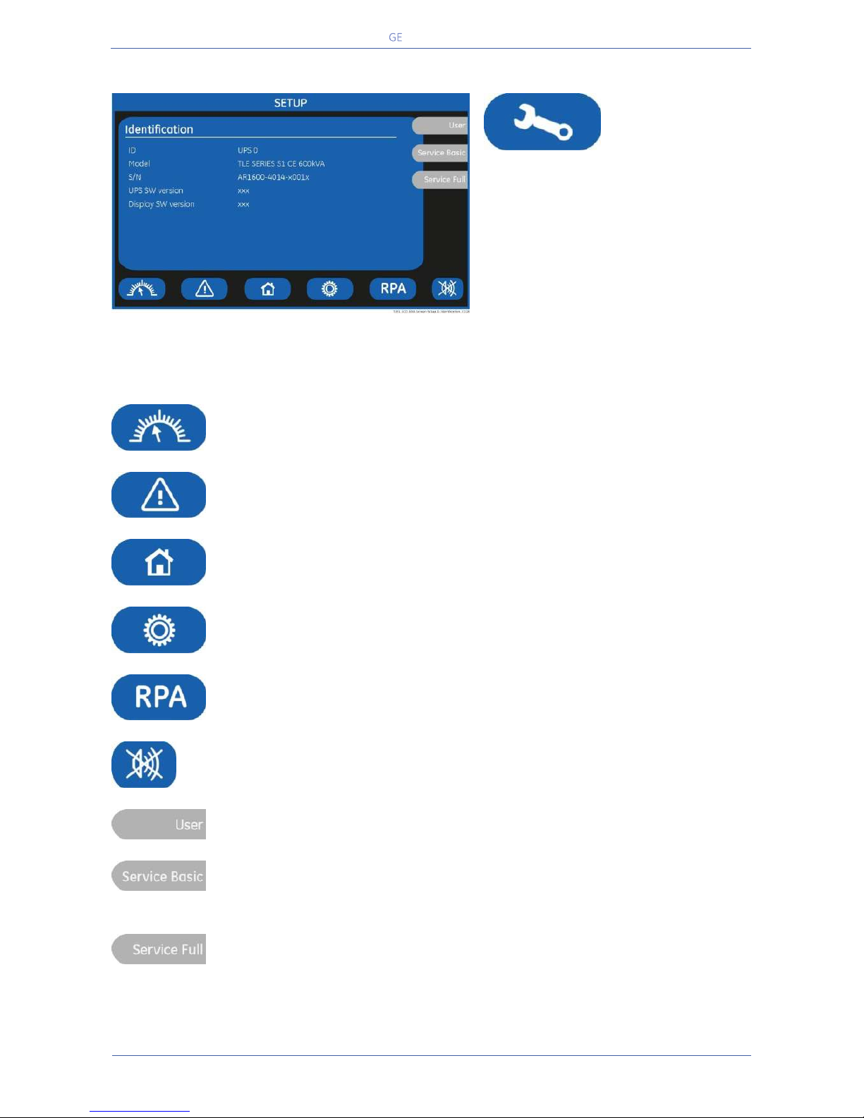
Critical Power
Modifications reserved
Page 90/146
GE_UPS_OPM_TLE_SCE_M60_M80_1GB_V020.docx
User Manual TLE Series 600 & 800 CE S1
7.4 SETUP
SETUP
The SETUP mode is entered any time the
“SETUP” key is pressed.
This screen allows the user to modify
some parameters permitting to adapt
some functions of the UPS to his/her
needs, described as follows.
The LCD will display a series of screens
containing the user parameters,
accessible without password protection.
In this mode the keys perform the following functions:
Shows the main screen MEASURES.
See Section 7.2.
Shows the main screen EVENTS.
See Section 7.3.
Return to HOME screen.
Shows the main screen COMMANDS.
See Section 7.5.
Shows the operating status of the RPA PARALLEL SYSTEM.
See Section 7.6.
Key to reset general alarm and buzzer.
Shows the screen User.
Shows the screen Service Basic.
Reserved for the Service Centre, at this level the parameters access is protected by a
code.
Shows the screen Service Full.
Reserved for the Service Centre, at this level the parameters access is protected by a
code.
Page 91
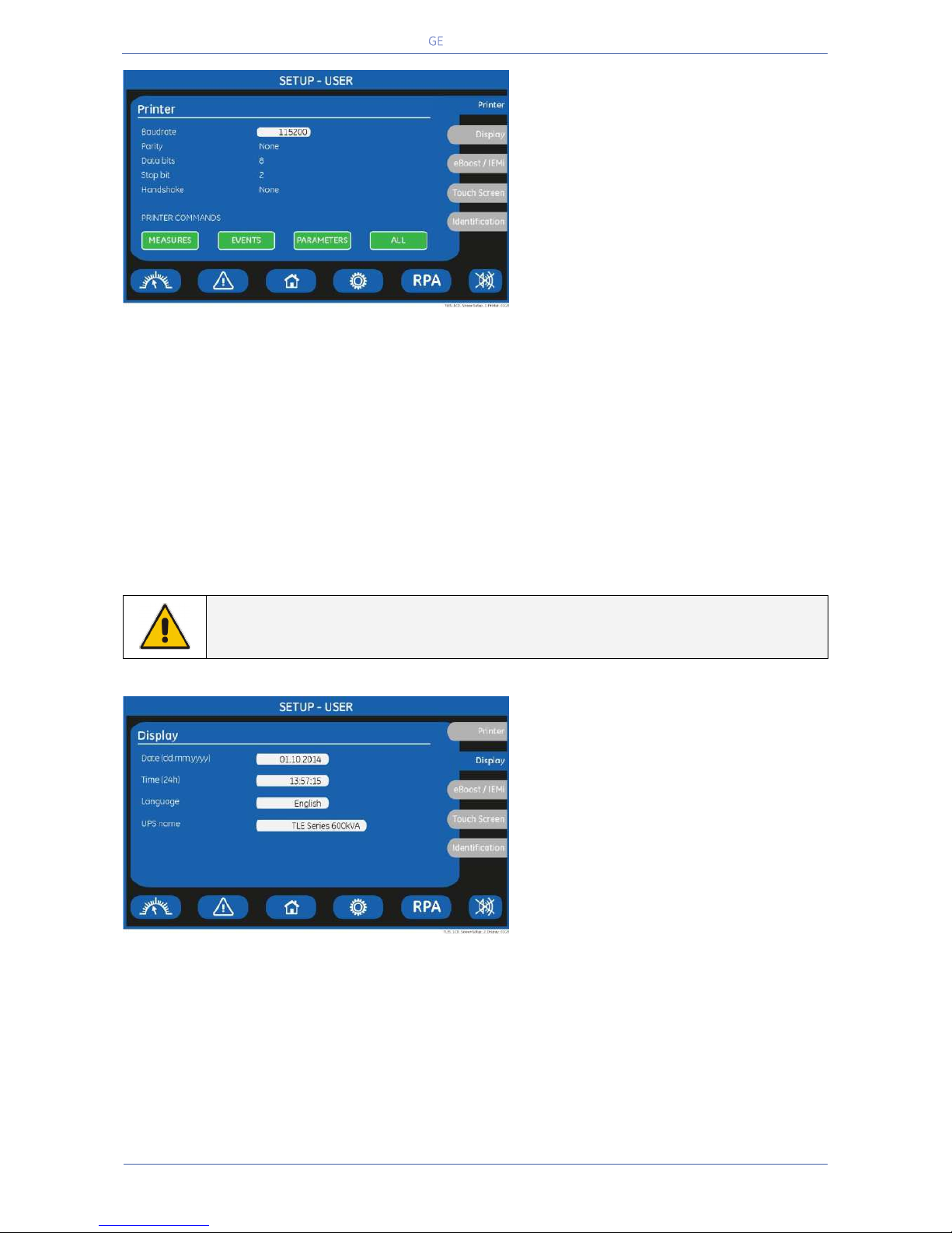
Critical Power
Modifications reserved
Page 91/146
GE_UPS_OPM_TLE_SCE_M60_M80_1GB_V020.docx
User Manual TLE Series 600 & 800 CE S1
PRINTER SCREEN
The UPS is capable of communicating to
a serial printer, to printout disparate
information.
Please be sure to have a serial printer
with a serial RS232 interface.
This is the only printer-interface
supported by the UPS.
Baudrate
This parameter controls the baud rate
used for data transmission.
Parity
This parameter controls the parity used for data transmission.
odd / even / None can be selected.
In case “None” has been set, automatically the parameter “Data bits = 8” is used,
independently of the value of “Data Bits” set.
Data bits
This parameter controls the length of the data word on the serial line during data
transmission.
Stop bit
Parameter non programmable.
Handshake
This parameter is used to determine the communication protocol used when
printing.
Valid values are “XON” standing for the XON/XOFF protocol or “None” standing for
any protocol.
PRINTER
COMMANDS
By using the keys MEASURES / ALARMS / PARAMETERS / ALL it is possible to print
selected data
NOTE !
Please configure your printer with the following parameters:
115200/None/8/2/None (115200 bauds/sec, no parity, 8 bits, 2 stop bits, no Handshake).
DISPLAY SCREEN
Date
You can adjust the date of the real time
clock existing in the UPS by the means of
this parameter (“dd-day, mm-month, yyyy-
year”).
The value you enter is thoroughly
checked to be a correct date in the
format “dd.mm.yyyy”.
Time
You can adjust the time of the real time clock existing in the UPS by means of this
parameter.
The value you enter is thoroughly checked to be a correct time in the format
“HH.MM.SS”. The time is specified in 24-hour format.
Language
This parameter allows the choice of language used to display the information.
Valid choices are: English, German, Italian, Spanish, French, Finnish, Polish,
Portuguese, Czech, Slovenian, Chinese, Swedish, Russian and Dutch.
UPS name
The user can choose the name of the UPS model shown on the main screen (max.
20 characters).
Page 92
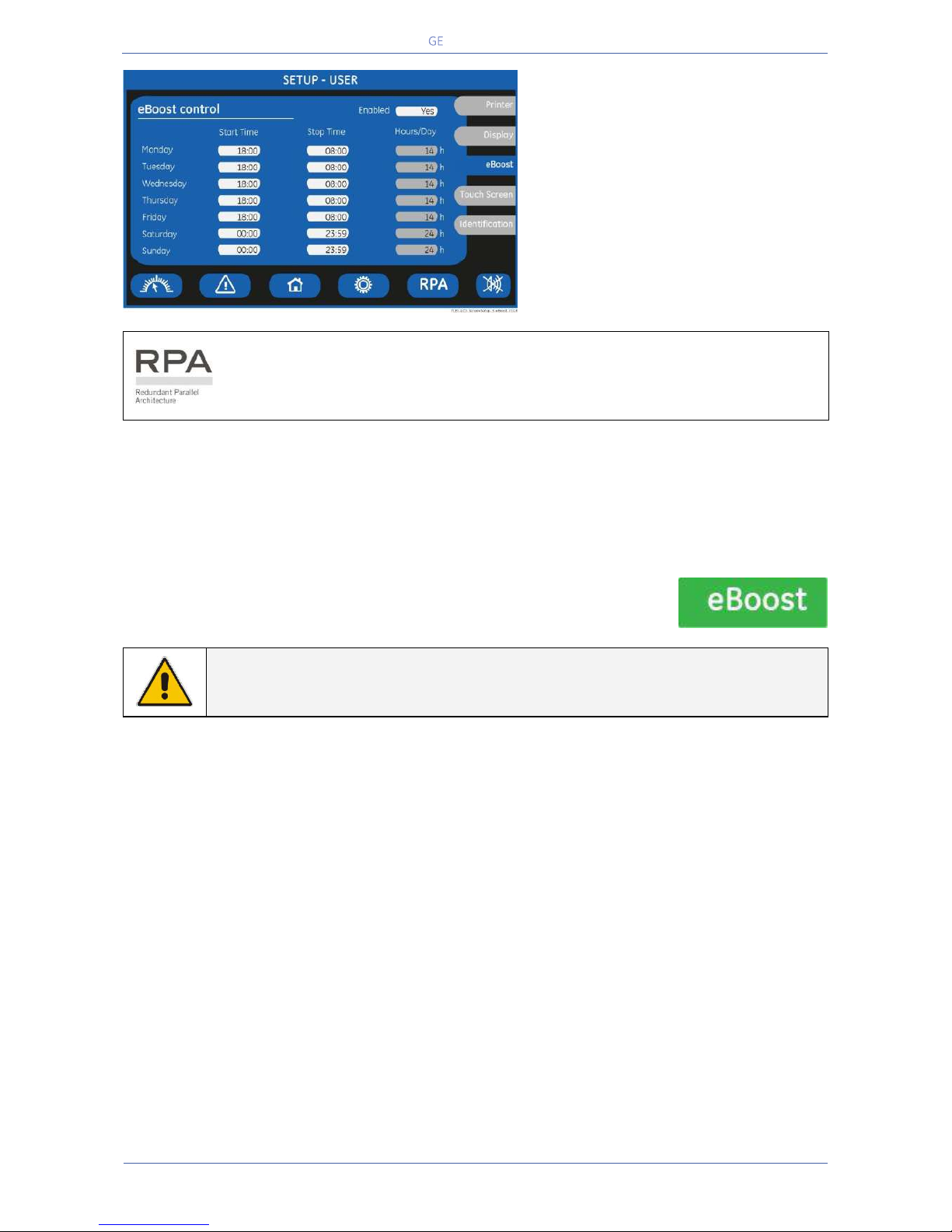
Critical Power
Modifications reserved
Page 92/146
GE_UPS_OPM_TLE_SCE_M60_M80_1GB_V020.docx
User Manual TLE Series 600 & 800 CE S1
eBOOST SCREEN (option)
This screen is displayed only when
eBoost™ Operation Mode is available
(option).
Enabled
This parameter (values Yes/No) enables
or disables the eBoost™ Operation
Mode.
If the value is “Yes” and the current time
is in the interval for the current day, the
eBoost™ Operation Mode is active.
In case of RPA Parallel System
If eBoost™ Operation Mode is currently disabled (No) and Q1 is closed, when
programming it to enable (Yes) the selected configuration will automatically be
propagated to all units in the RPA Parallel System.
The activation / deactivation of eBoost™ Operation Mode is indicated each time in the event list.
In order to check the inverter function, at least 1 minute of VFI mode must be programmed during the
week (the Yes/No parameter is automatically disabled if this condition is not satisfied).
In case this minimum time in VFI mode is not respected, the eBoost™ Operation Mode will be disabled.
If the value is “No”, the UPS is normally operating in VFI / double conversion mode at all times.
When the UPS is in eBoost™ Operating Mode the eBoost LED is ON (green
light).
NOTE !
The configuration of the activation schedule can only be updated when eBoost™ Operation
Mode is disabled (Enabled: No).
DAY
For the weekdays from “Monday to Sunday”, the edit mode (edit day) allows to define time intervals
when the UPS is operating in eBoost™ Operation Mode. The hour is given in 24-hour format.
These intervals are defined by:
Start Time: The hour of the day after which the eBoost™ Operation Mode is enabled.
The eBoost™ Operation Mode is enabled until the following “Stop Time” time is reached
(the “Stop Time” time of the same day if this is later than the “Start Time” time, the “Stop
Time” time of the following day otherwise).
Stop Time: The hour of the day before which the eBoost™ Operation Mode is enabled.
The eBoost™ Operation Mode is enabled starting from the preceding “Start Time” time (the “Start Time”
time of the same day if this is earlier than the “Stop Time” time, the “Start Time” time of the previous
day otherwise).
Identical times for “Start Time” and “Stop Time” maintain the existing mode only in case the previous
command was “Start Time” and the following command will be “Stop Time”.
Page 93
Critical Power
Modifications reserved
Page 93/146
GE_UPS_OPM_TLE_SCE_M60_M80_1GB_V020.docx
User Manual TLE Series 600 & 800 CE S1
HOURS/DAY
The number of eBoost™ Operation Mode hours per weekday “Monday to Sunday” is displayed in the
operation mode parameter window (ceiling value).
NOTE !
To avoid undesired eBoost™ Operation Mode, verify:
Date and Time.
eBoost™ screen how many hours of eBoost™ Operation Mode have been
selected for each day of the week.
NOTE !
The eBoost™ Operation Mode will become active only if the Load is supplied from
the Inverter.
eBoost™ Operation Mode is only possible if the UPS load exceeds a minimum
threshold (default 10% of the rated capacity).
In case no-load conditions, or anyway below said threshold, the UPS operates in VFI
mode.
Page 94
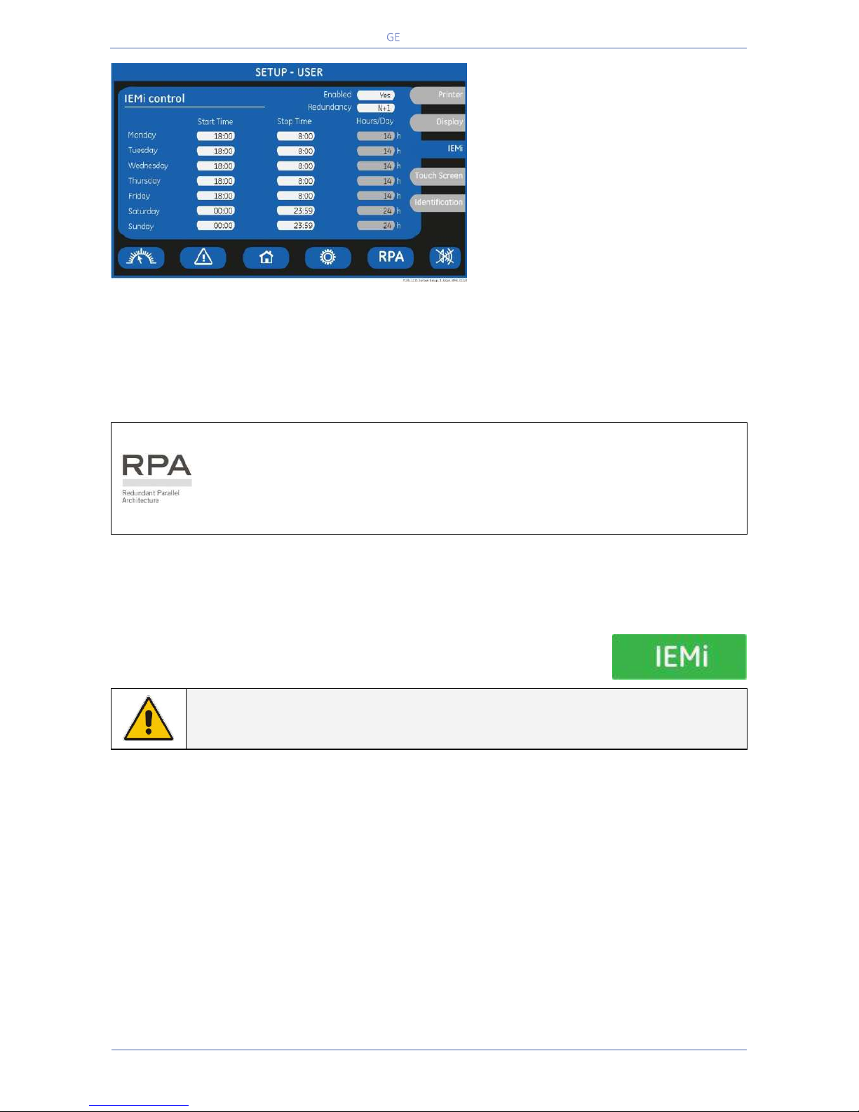
Critical Power
Modifications reserved
Page 94/146
GE_UPS_OPM_TLE_SCE_M60_M80_1GB_V020.docx
User Manual TLE Series 600 & 800 CE S1
IEMi SCREEN (option)
This screen is displayed only when IEMi
Operation Mode is available (option).
Enabled
This parameter (values Yes/No) enables
or disables the IEMi Operation Mode.
If the value is “Yes” and the current time
is in the interval for the current day, the
IEMi Operation Mode.
Redundancy
N + … Redundancy level: N+1, N+2.
Note: the redundancy level can only be updated when IEMi Operation Mode is disabled (Enabled: No).
In order to enjoy the benefits of IEMi Operation Mode operation a system programmed for N+1
redundancy requires a parallel installation of at least three UPSs, while four UPSs are required
for N+2 redundancy.
The IEMi Operation Mode must be available on all units in a Parallel System.
In case of RPA Parallel System
If IEMi Operation Mode is currently disabled (No) and Q1 is closed, when programming
it to enable (Yes) the selected configuration will automatically be propagated to all
units in the RPA Parallel System.
If IEMi Operation Mode is currently enabled (Yes) and Q1 is closed, when programming
it to disable (N) all stand-by inverters in the system will be switched on-line.
The activation / deactivation of IEMi Operation Mode is indicated each time in the event list. In order to
force a test of all Inverters in the system, at least 1 minute of normal operation must be programmed
during the week (the Yes/No parameter is automatically disabled if this condition is not satisfied).
In case this minimum time in normal VFI operation is not respected, the IEMi Operation Mode will be
disabled. If the value is “No”, the UPS is operating in normal VFI / double conversion mode at all times.
When the UPS is in IEMi Operating Mode the IEMi LED is ON (green light).
NOTE !
The configuration of the activation schedule can only be updated when IEMi
Operation Mode is disabled (Enabled: No).
DAY
For the weekdays from “Monday to Sunday”, the edit mode (edit day) allows to define time intervals
when the UPS is operating in IEMi Operation Mode. The hour is given in 24-hour format.
These intervals are defined by:
Start Time: The hour of the day after which the IEMi Operation Mode is enabled.
The IEMi Operation Mode is enabled until the following “Stop Time” time is reached (the
“Stop Time” time of the same day if this is later than the “Start Time” time, the “Stop
Time” time of the following day otherwise).
Stop Time: The hour of the day before which the IEMi Operation Mode is enabled.
The IEMi Operation Mode is enabled starting from the preceding “Start Time” time (the “Start Time” time
of the same day if this is earlier than the “Stop Time” time, the “Start Time” time of the previous day
otherwise).
Identical times for “Start Time” and “Stop Time” maintain the existing mode only in case the previous
command was “Start Time” and the following command will be “Stop Time”.
Page 95
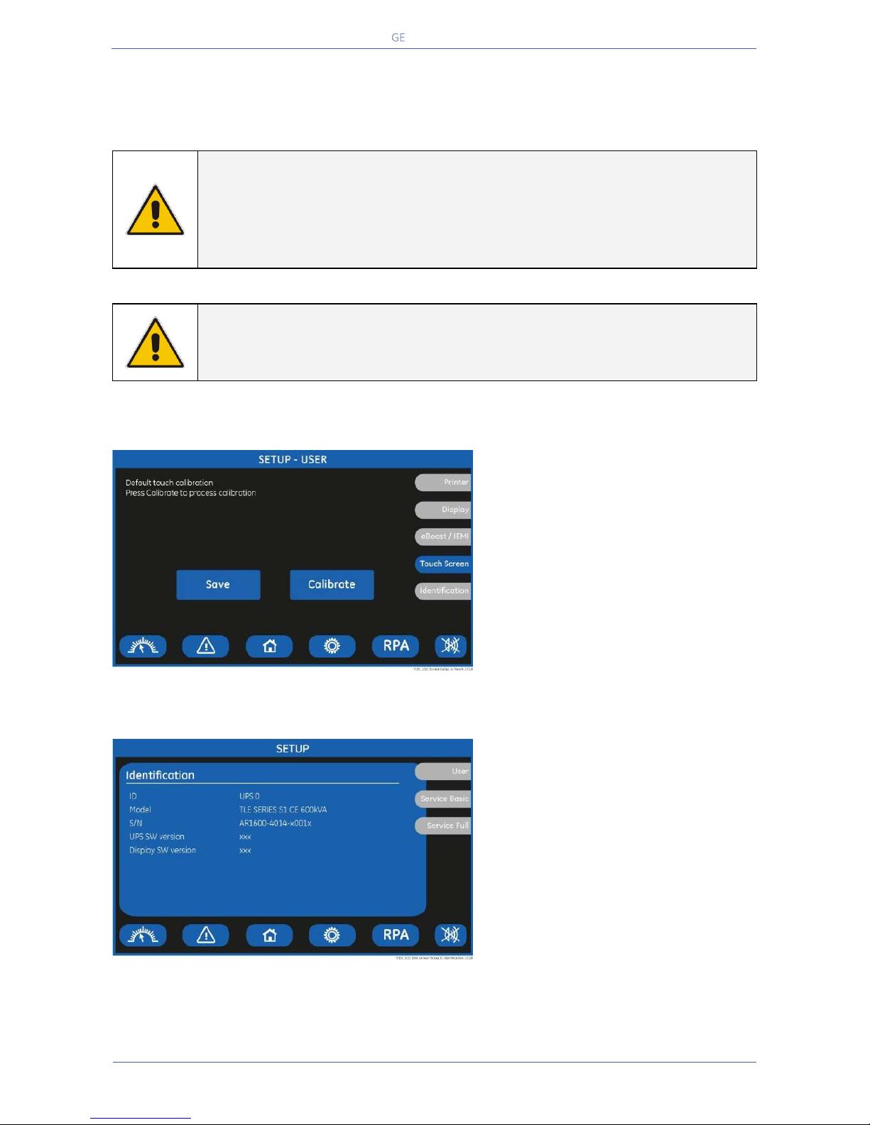
Critical Power
Modifications reserved
Page 95/146
GE_UPS_OPM_TLE_SCE_M60_M80_1GB_V020.docx
User Manual TLE Series 600 & 800 CE S1
HOURS/DAY
The number of IEMi Operation Mode hours per weekday “Monday to Sunday” is displayed in the
operation mode parameter window (ceiling value).
NOTE !
To avoid undesired IEMi Operation Mode, verify:
Date and Time.
IEMi screen how many hours of IEMi Operation Mode have been selected for
each day of the week.
NOTE !
For IEMi Operation Mode to become active a manual Inverter start is required at
start-up and after a “System shutdown reset”.
TOUCH SCREEN
This screen permits the adjustment
(“Calibrate” key) of the LCD’s “Touch
Screen” sensitivity.
IDENTIFICATION SCREEN
ID
Number of UPS in the RPA Parallel
System (0 for single unit).
Model
UPS model, power range and series
number.
S/N
The UPS serial number.
UPS SW version
The UPS software version.
Display SW version
The LCD display software version.
Page 96
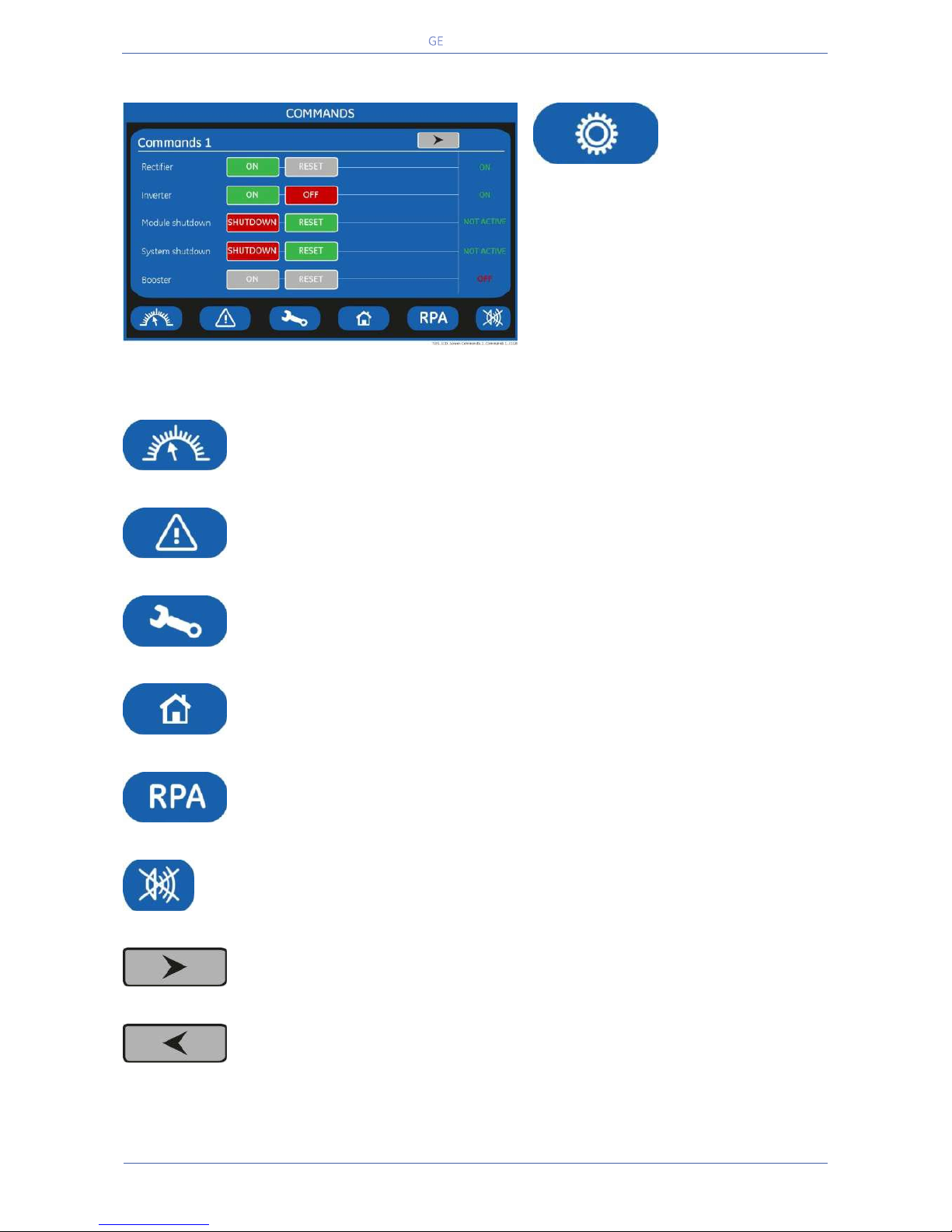
Critical Power
Modifications reserved
Page 96/146
GE_UPS_OPM_TLE_SCE_M60_M80_1GB_V020.docx
User Manual TLE Series 600 & 800 CE S1
7.5 COMMANDS
COMMANDS
The COMMANDS mode is entered any time
the “COMMANDS” key is pressed.
Allows the user to execute UPS operation
commands.
In this mode the keys perform the following functions:
Shows the main screen MEASURES.
See Section 7.2.
Shows the main screen EVENTS.
See Section 7.3.
Shows the main screen SETUP.
See Section 7.4.
Return to HOME screen.
Shows the operating status of the RPA PARALLEL SYSTEM.
See Section 7.6.
Key to reset general alarm and buzzer.
Shows the screen Commands 2.
Shows the screen Commands 1.
Page 97
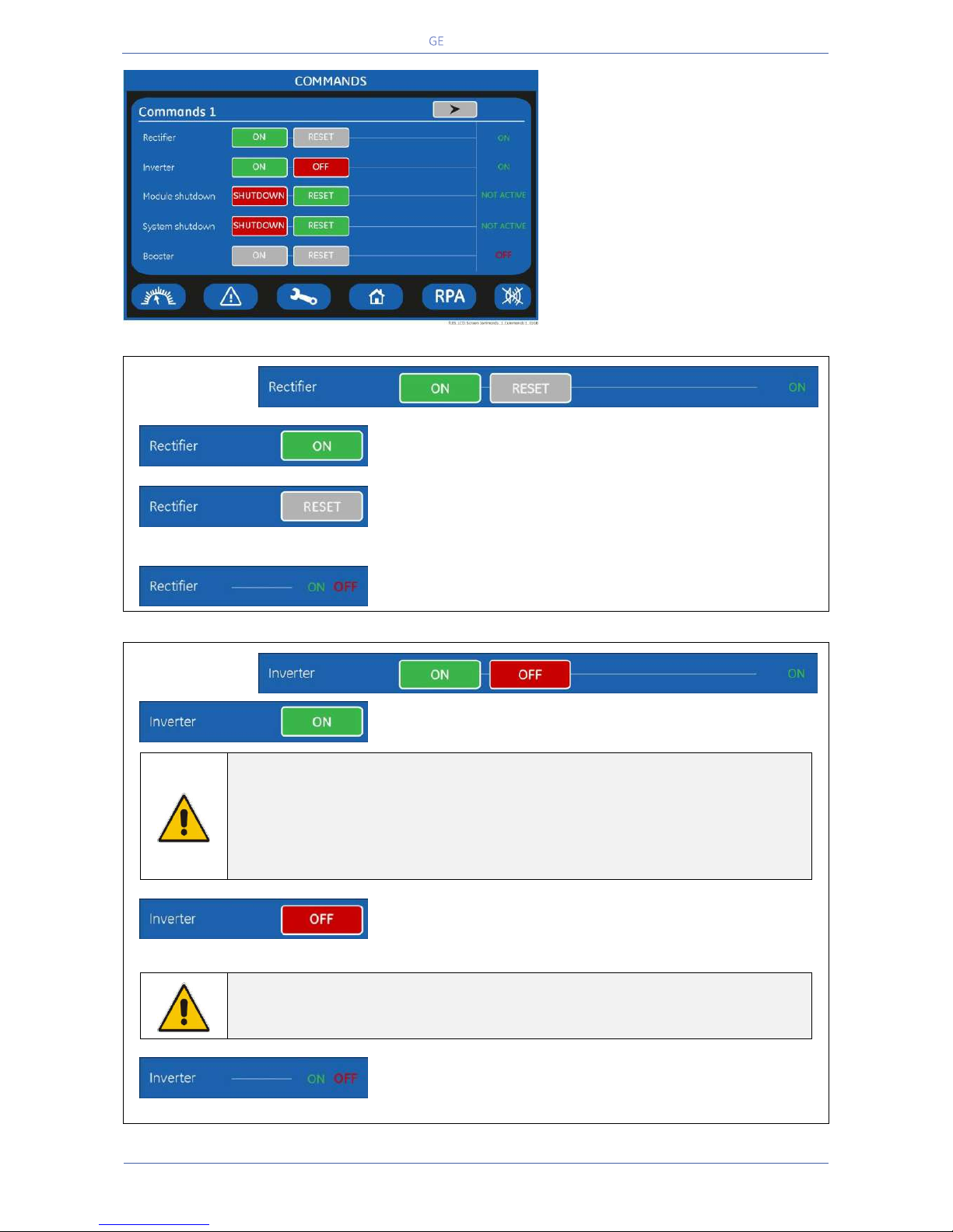
Critical Power
Modifications reserved
Page 97/146
GE_UPS_OPM_TLE_SCE_M60_M80_1GB_V020.docx
User Manual TLE Series 600 & 800 CE S1
COMMANDS 1 SCREEN
Allows the user to execute UPS
operation commands.
Rectifier
Rectifier ON
Rectifier switching ON command.
Rectifier RESET
Rectifier restore command.
Reserved for the Service Centre.
Led Rectifier status
Indicates the Rectifier’s status: ON = lit OFF = turned Off
Inverter
Inverter ON
Inverter switching ON command.
NOTE !
When eBoost™ Operation Mode or IEMi Operation Mode is enabled, control of
Inverter status and selection of the feed path is done autonomously by the
UPS control logic.
Therefore, Inverter ON / Inverter OFF commands are disabled when eBoost™
Operation Mode or IEMi Operation Mode is enabled.
Inverter OFF
Inverter switching OFF command.
This command is also used as EPO (Emergency Power Off) reset after the contact closing.
NOTE !
Inverter OFF command is disabled when eBoost™ Operation Mode or IEMi
Operation Mode is enabled.
Led inverter status
It indicates the Inverter status:
ON / OFF / Pre-charge / Pre-charge completed / Soft-start
Page 98
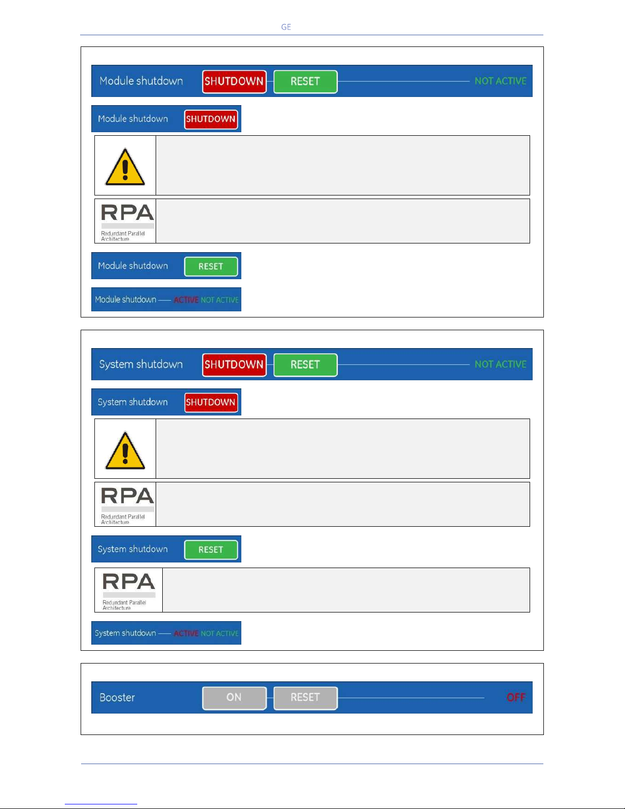
Critical Power
Modifications reserved
Page 98/146
GE_UPS_OPM_TLE_SCE_M60_M80_1GB_V020.docx
User Manual TLE Series 600 & 800 CE S1
Module shutdown
Module shutdown
Load Off command for a single UPS.
ATTENTION !
THIS COMMAND WILL IMMEDIATELY DISCONNECT THE LOAD.
“Module shutdown” cannot disconnect the UPS from the Load with “Q2 -
Manual Bypass switch” (only if provided by customer) closed.
For the RPA Parallel System
In an RPA Parallel System, the “Module shutdown” command disconnects the
Load to the selected unit only (switch Q1 closed).
Module shutdown RESET
“Module shutdown” restore command for an individual UPS.
Led Module shutdown status
Shows the “Module shutdown” status: ACTIVE / NOT ACTIVE
System shutdown
System shutdown
Load Off command for an RPA Parallel System.
ATTENTION !
THIS COMMAND WILL IMMEDIATELY DISCONNECT THE LOAD.
“System shutdown” cannot disconnect the RPA Parallel System from the
Load with Q2 (only if provided by customer) closed.
For the RPA Parallel System
If “System shutdown” is pressed on one unit connected to the Parallel Bus
(switch Q1 closed), all the units are separated from the Load.
System shutdown RESET
“System shutdown” restore command for a RPA Parallel System.
For the RPA Parallel System
The “System shutdown RESET” must be done only on one unit connected to the
parallel bus (switch Q1 closed).
Led System shutdown status
Shows the “System shutdown” status: ACTIVE / NOT ACTIVE
Booster
Only for Service Centre.
Page 99
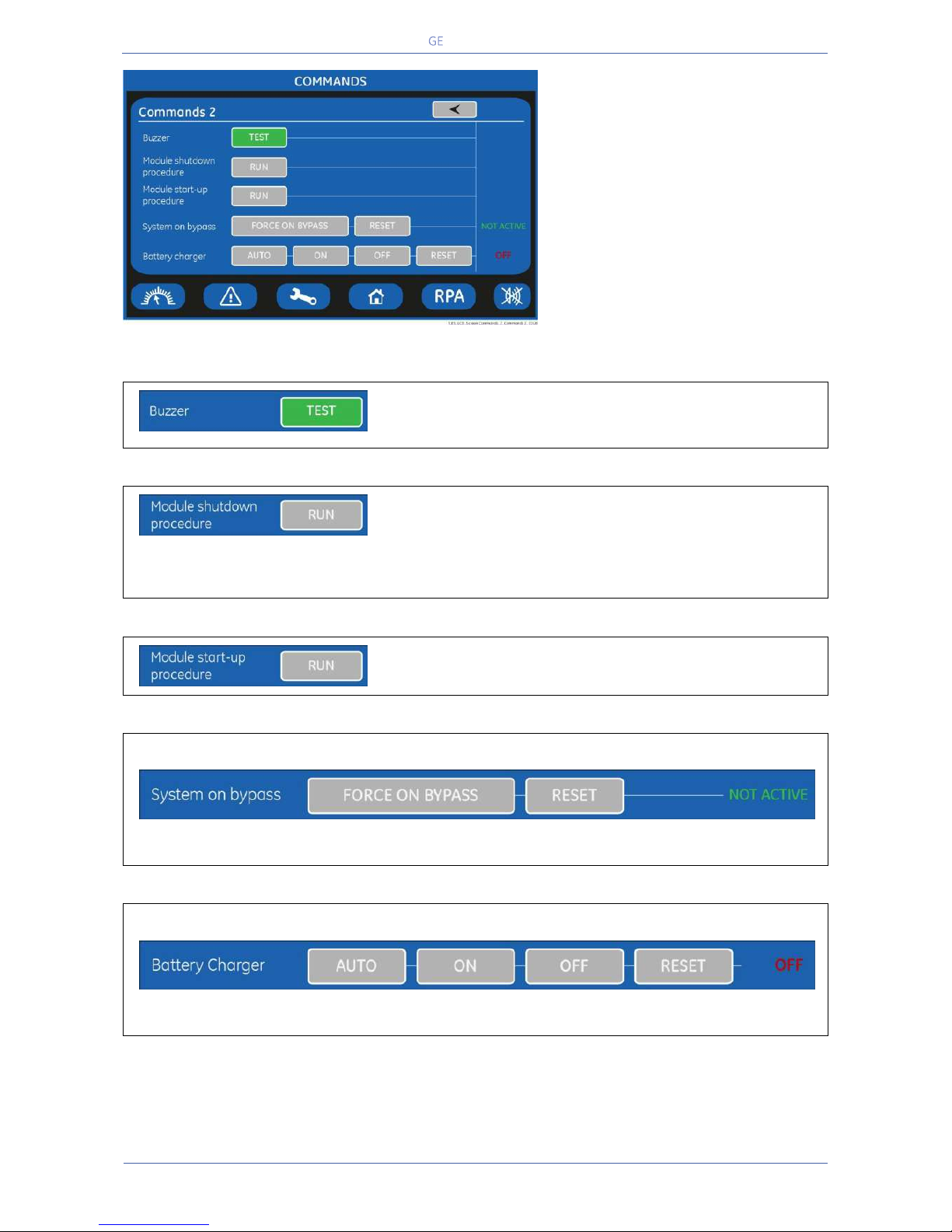
Critical Power
Modifications reserved
Page 99/146
GE_UPS_OPM_TLE_SCE_M60_M80_1GB_V020.docx
User Manual TLE Series 600 & 800 CE S1
COMMANDS 2 SCREEN
Allows the user to execute UPS
operation commands.
Buzzer TEST
Acoustical alarm test (acoustical alarm should be always
activated).
Module shutdown procedure
Guides throught the procedures to shutdown a single UPS or
a RPA Parallel System unit.
Attention: For a single UPS this implies the load
disconnection.
Module start-up procedure
Guides throught the procedures to start-up the UPS.
System on bypass
Function not enabled.
Battery Charger
Function not enabled.
Page 100
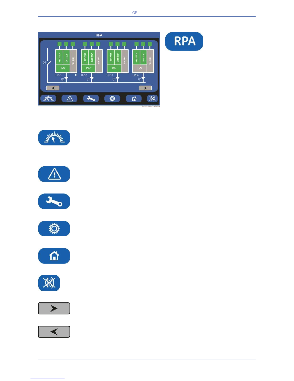
Critical Power
Modifications reserved
Page 100/146
GE_UPS_OPM_TLE_SCE_M60_M80_1GB_V020.docx
User Manual TLE Series 600 & 800 CE S1
7.6 RPA PARALLEL SYSTEM
RPA
PARALLEL SYSTEM
(option)
The RPA PARALLEL SYSTEM is entered any
time the “RPA” key is pressed.
This screen is only displayed when the
RPA Parallel System is available (option).
The LCD screen will provide some
information on the RPA Parallel System.
In this mode the keys perform the following functions:
Shows the main screen MEASURES.
See Section 7.2.
NOTE! During IEMi Operation Mode, the “Percent Load” information is computed
based on on-line units only.
Shows the main screen EVENTS.
See Section 7.3.
Shows the main screen SETUP.
See Section 7.4.
Shows the main screen COMMANDS.
See Section 7.5.
Return to HOME screen.
Key to reset general alarm and buzzer.
Shows the screen for the next RPA Parallel System units
Shows the screen of the previous RPA Parallel System units.
 Loading...