

GE
Lighting Solutions
®
Tetra
(GEPS24-300U-GL)
Power Supply Features
• Supports Tetra PowerStrip, Tetra MiniStrip, Tetra EdgeStrip,
Tetra Contour, Contour LS, and Line Fit Light lighting systems
• UL: Class 2 wiring per NEC Article 725.
• Limited to use in dry and damp locations.
• The suitability of rain enclosure shall be determined if
intended for wet location.
• Minimum 5 cm (2 in.) spacing from heat producing
components required.
• Minimum 4 to side and 1 in. spacing in compartment
surrounding component required.
• Three 96 watt output banks.
LED Systems Power Supply
Installation Guide
24
Volt
BEFORE YOU BEGIN
Read these instructions completely and carefully.
WARNING/AVERTISSEMENT
RISK OF ELECTRIC SHOCK
• Disconnect power at fuse box or circuit breaker before servicing or
installing product.
• Properly ground Tetra
RISK OF FIRE
• Use only Tetra
power supply to Tetra
• Use only approved wire for input/output connection. Minimum size
18 AWG (0.82 mm
• Follow all local codes.
This device complies with part 15 of the FCC Rules. Operation is subject to the following two conditions: (1) This device may not cause harmful interference,
and (2) this device must accept any interference received, including interference that may cause undesired operation.
Note: This equipment has been tested and found to comply with the limits for a Class A digital device, pursuant to part 15 of the FCC Rules. These limits are
designed to provide reasonable protection against harmful interference when the equipment is operated in a commercial environment . This equipment
generates, uses, and can radiate radio frequency energy and, if not installed and used in accordance with the instruction manual, may cause harmful
interference to radio communications. Operation of this equipment in a residential area is likely to cause harmful interference in which case the user will
be required to correct the interference at his own expense.
This Class [A] RFLD complies with the Canadian standard ICES-003. Ce DEFR de la classe [A] est conforme à la NMB-003 du Canada.
®
power supply.
®
supply wire to make connection from Tetra®
®
LED strip.
2
)
RISQUES DE DÉCHARGES ÉLECTRIQUES
• Coupez l’alimentation électrique à la boîte de fusibles ou au disjoncteur
avant l’entretien ou l’installation du produit.
• Assurez-vous de correctement mettre à terre l’alimentation
électrique Tetra
RISQUES D’INCENDIE
entre l’alimentation Tetra® et la bande DEL Tetra®.
Taille minimum 18 AWG (0.82 mm2).
• Respectez tous les codes locaux.
• Avrisques d’incendie ou de choc lectriques. Ne pas interconnecter les
bornes de sortie.
®
.
®
pour faire la connexion
imagination at work
Power Supply Installation
To Tetra LED System
White
(neutral)
Black
(line)
AC line
Output wires
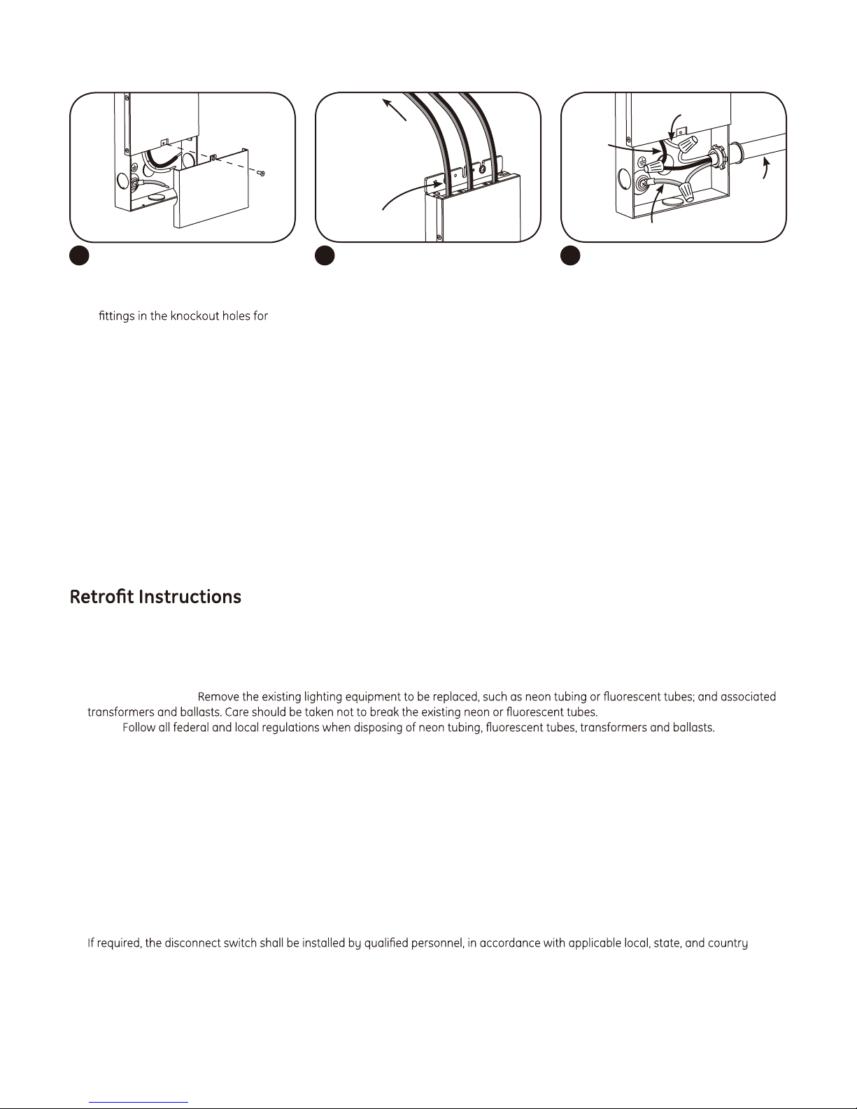
Mount power supply and remove
1 3
junction box cover. Carefully
remove knockout for AC line input
wires. Install appropriate electrical
wire protection.
NOTE: For installation in Canada, a disconnect switch of appropriate rating needs to be placed within 29.5 ft. (9 m) of primary side of
the power supply. The switch voltage rating shall not be less than the branch circuit voltage. The switch must also support twice the
amount of input current.
NOTE: When installing power supply, connect to the appropriate sized building breaker or disconnect device for line, neutral and
ground connections, in accordance with National Electric Code (NEC) Article 600 and all local regulations.
NOTE: Exceeding maximum load per bank will cause the LEDs to dim or blink. Once the excess load is removed, cycle the input power
to restart the power supply.
Connect the supply wire that is
2
attached to the Tetra LED System to
the red (+) and black (-) output wires
of the power supply as outlined in
the “Electrical Connections” section
of your LED system’s Installation
Instructions.
NOTE: Three 96 watt output
banks per power supply. Do not
interconnect output terminations.
Green with yellow stripe (ground)
Connect the AC line to the black (line)
and white (neutral) input wires of
the power supply and connect the
branch circuit ground to the green
wire with a yellow stripe (ground) wire
using appropriately sized twist-on
wire connectors.
1. (Existing Signs Only) Prior to installation, survey the site for information regarding power and accessibility inside and outside the
building. Ensure that the branch circuit supplying the existing transformer or ballast will be within the voltage ratings of the new
LED power supply, and have a current rating not exceeding 20A, or that permitted by applicable local, state, or country electrical codes
(whichever is less).
2. (Existing Signs Only)
NOTE:
3. (Existing Signs Only) If removal of the existing lighting equipment eliminates the disconnect switch, as required by applicable local,
state, or country electrical codes; a new disconnect switch must be installed.
4. (Existing Signs Only) Make sure the removal of lighting equipment does not compromise the integrity of the sign body (i.e. water
intrusion). Fill in all holes 0.5 in. (13 mm) or smaller with the appropriate amount of rated caulk or sealant. For holes greater than
0.5 in. (13 mm), use an aluminum or zinc coated steel patch with rivets and sealant.
5. Using the layout guidelines within the LED module installation instructions, determine required number of LED modules required to
illuminate the sign.
6. Using the applicable LED module maximum Loading chart, determine the number of Tetra Class 2 Power Supplies required to power the
number of LED modules required to illuminate the sign, so as not to overload any single power supply output.
7. Follow the LED module instructions to properly mount the LED modules.
8. Connect the DC output of the power supply to the LED modules using the Power Supply Installation instructions above.
9. Connect AC power to the power supply in accordance with the applicable local, state, and country electrical codes, and the Power
Supply Installation instructions above.
10.
electrical codes.
 Loading...