

GE Tetra GEPS24-100U-NA Installation Manual
Tetra
® LED Systems
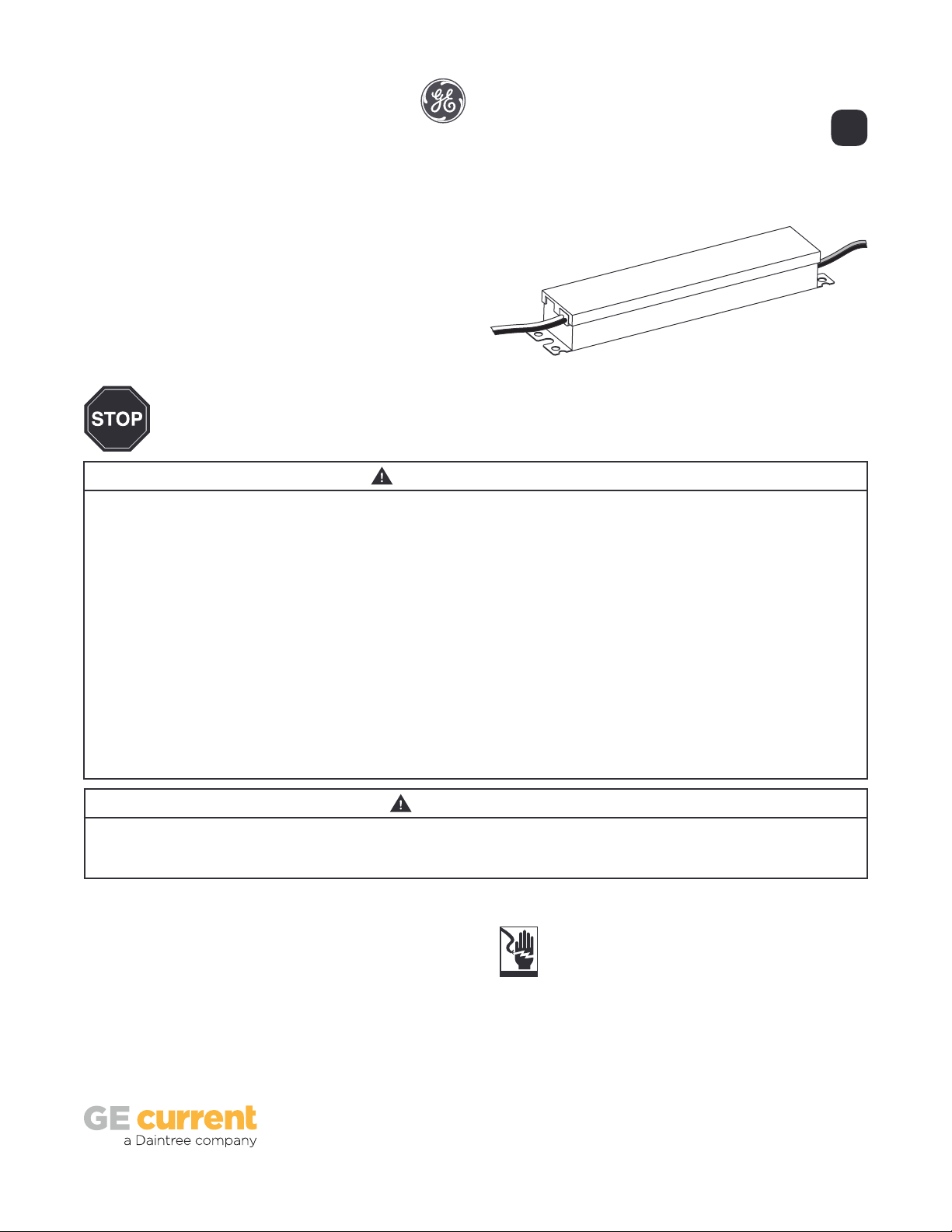
Power Supply
Installation Guide
24
Volt
GEPS24-100U-NA
( VAC input / VDC output / 100W)120-277 24
Power Supply Features
• Supports all 24 VDC Tetra Products
• Dry and Damp Locations Rated
• Class 2 Power Supply
• 120-277 VAC Input
BEFORE YOU BEGIN
Read these instructions completely and carefully.
WARNING/AVERTISSEMENT
RISK OF ELECTRIC SHOCK
• Disconnect power at fuse box or circuit breaker before servicing
or installing product.
• Properly ground Tetra® power supply.
• AC input connections shall be suitably enclosed. The power
supply shall be enclosed or made inaccessible to users during
normal use.
RISK OF FIRE
• Minimum power supply spacing to other power supply or other
heat producing component shall be at least 4” (101.6 mm) from
side to side and 1” (25.4mm) from end to end.
• Use only approved wire for input/output connection. Minimum
size 18 AWG (0.82 mm2).
• Follow all local codes.
• Application considerations potentially requiring additional
spacing include high ambient temperature seen by the
power supply, poor contact with a heat dissipating material,
inadequate ventilation, or direct exposure to sun.
RISQUES DE DÉCHARGES ÉLECTRIQUES
• Coupez l’alimentation électrique à la boîte de fusibles ou au disjoncteur avant
l’entretien ou l’installation du produit.
• Assurez-vous de correctement mettre à terre le bloc d’alimentation Tetra®.
• Les connexions d’entrée CA doivent être convenablement enfermées. Le bloc
d’alimentation doit être enfermée ou rendue inaccessible aux utilisateurs
pendant l’utilisation normale.
RISQUES D’INCENDIE
• L’espacement minimal du bloc d’alimentation par rapport à un autre bloc
d’alimentation ou aux autres composants produisant de la chaleur doit
être au moins 4” (101,6 mm) de chaque côté et 1” (25,4 mm) de bout en
bout.
• N’utilisez que des ls approuvés pour les entrées/sorties de connexion.
Taille minimum 18 AWG (0.82 mm2).
• Respectez tous les codes locaux.
• Certaines applications pourraient requérir un espacement additionnel, p.
ex. une température ambiante élevée autour du bloc d’alimentation, un
mauvais contact avec une matière dissipatrice de chaleur, une ventilation
inadéquate ou une exposition directe au soleil.
RISK OF INJURY
• While performing installations described, gloves, safety
glasses or goggles should be worn.
Save These Instructions
Use only in the manner intended by the manufacturer.
If you have any questions, contact the manufacturer.
CAUTION/ATTENTION
RISQUES DE BLESSURE
• Lors de l’exécution des installations décrites, des gants, des lunettes de
sécurité ou des lunettes de protection doivent être portées.
Prepare Electrical Wiring
Electrical Requirements
• Limited to use in dry and damp locations.
• The suitability of rain enclosure shall be determined if
intended for wet location.
• The grounding and bonding of the LED Driver shall be
done in accordance with National Electric Code (NEC)
Article 600.
• Follow all National Electric Codes (NEC) and local codes.
1
Power Supply Installation
To Tetra LED System
Input
wires
White or blue
(neutral)
AC line
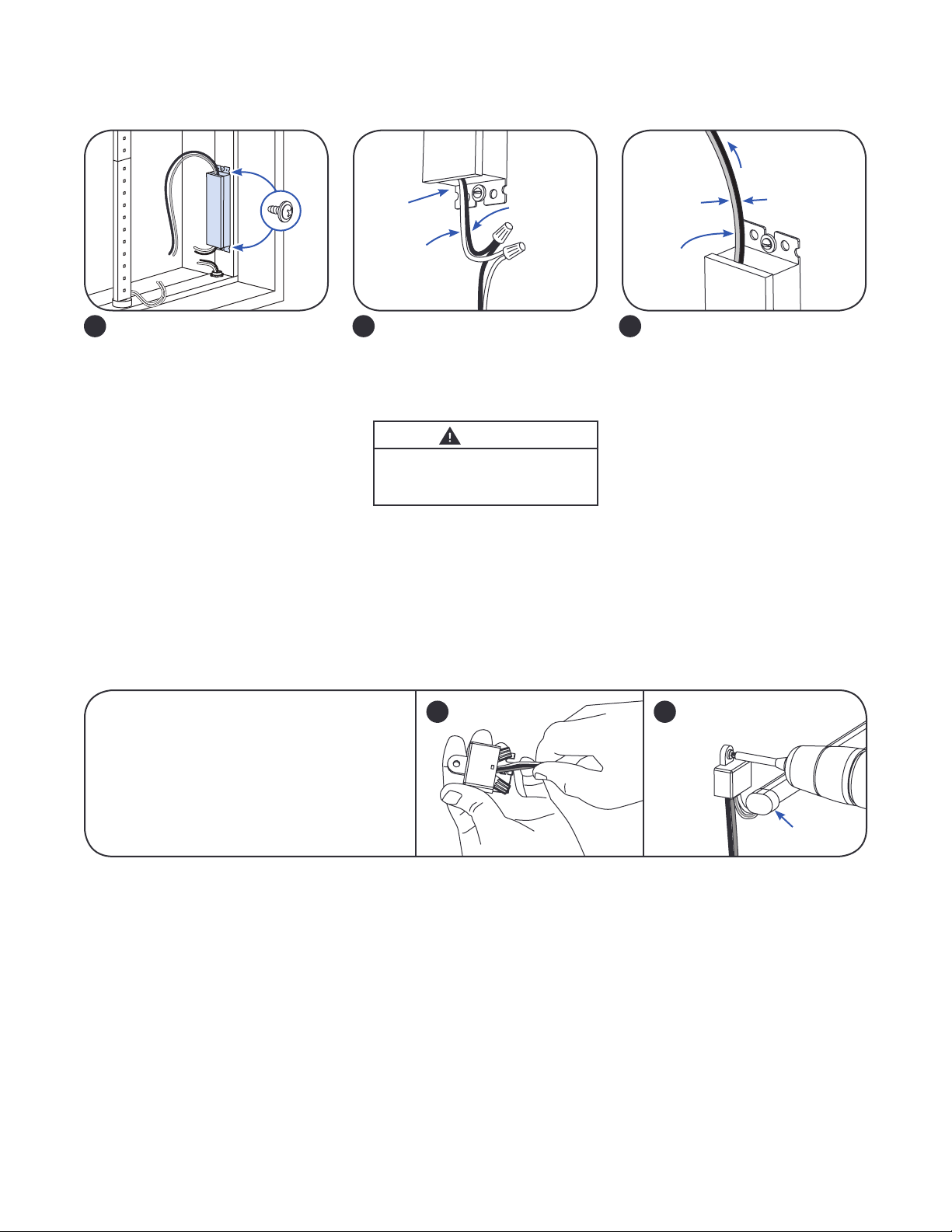
Mount the power supply. Mounting
1
the power supply base directly to
a thermally conductive installation
surface can improve thermal
performance.
NOTE: All electrical connections
should be suitably protected from
mechanical damage and the
environment. Seal all connections
exposed to water with electrical
grade self-hardening silicone.
NOTE: For installation in Canada, a disconnect switch of appropriate rating needs to be placed within 29.5 feet (9 meters) of primary
side of the power supply. The switch voltage rating shall not be less than the branch circuit voltage. The switch must also support
twice the amount of input current.
NOTE: When installing power supply, connect to the appropriate sized building breaker or disconnect device for line, neutral and
ground connections, in accordance with National Electric Code (NEC) Article 600 and all local regulations.
Connect the AC line to the black
2
or brown (line) and white or
blue (neutral) input wires of the
power supply using suitable wire
connectors.
WARNING
RISK OF ELECTRIC SHOCK
AC input connections shall be
suitably enclosed.
Black or brown
(line)
Red (+)
Output
wires
Connect the supply wire that is
3
attached to the Tetra LED System to
the red (+) and black or blue (-) output
wires of the power supply as outlined
in the “Electrical Connections”
section of your LED system’s
Installation Instructions.
NOTE: To avoid overloading this
power supply with LED modules,
please refer to the specic module
loading guides.
Black or blue (-)
OPTIONAL
A Weather Box (GEXNWB2) may be used to house
and seal Class 2 connections.
A) Insert wire connectors into weather box. Fill
with electrical grade silicone and close box.
B) Secure the weather box using a #6 or #8 (M2
or M3) screw.
A B
Weather box
can be painted
Light engine
2
 Loading...